EP4549041A1 - Cold-rolling method and cold-rolling equipment - Google Patents
Cold-rolling method and cold-rolling equipment Download PDFInfo
- Publication number
- EP4549041A1 EP4549041A1 EP23857052.7A EP23857052A EP4549041A1 EP 4549041 A1 EP4549041 A1 EP 4549041A1 EP 23857052 A EP23857052 A EP 23857052A EP 4549041 A1 EP4549041 A1 EP 4549041A1
- Authority
- EP
- European Patent Office
- Prior art keywords
- steel sheet
- rolling mill
- leveling
- plane deformation
- amount
- Prior art date
- Legal status (The legal status is an assumption and is not a legal conclusion. Google has not performed a legal analysis and makes no representation as to the accuracy of the status listed.)
- Pending
Links
Images






Classifications
-
- B—PERFORMING OPERATIONS; TRANSPORTING
- B21—MECHANICAL METAL-WORKING WITHOUT ESSENTIALLY REMOVING MATERIAL; PUNCHING METAL
- B21B—ROLLING OF METAL
- B21B37/00—Control devices or methods specially adapted for metal-rolling mills or the work produced thereby
- B21B37/58—Roll-force control; Roll-gap control
- B21B37/66—Roll eccentricity compensation systems
-
- B—PERFORMING OPERATIONS; TRANSPORTING
- B21—MECHANICAL METAL-WORKING WITHOUT ESSENTIALLY REMOVING MATERIAL; PUNCHING METAL
- B21B—ROLLING OF METAL
- B21B37/00—Control devices or methods specially adapted for metal-rolling mills or the work produced thereby
- B21B37/58—Roll-force control; Roll-gap control
-
- B—PERFORMING OPERATIONS; TRANSPORTING
- B21—MECHANICAL METAL-WORKING WITHOUT ESSENTIALLY REMOVING MATERIAL; PUNCHING METAL
- B21C—MANUFACTURE OF METAL SHEETS, WIRE, RODS, TUBES, PROFILES OR LIKE SEMI-MANUFACTURED PRODUCTS OTHERWISE THAN BY ROLLING; AUXILIARY OPERATIONS USED IN CONNECTION WITH METAL-WORKING WITHOUT ESSENTIALLY REMOVING MATERIAL
- B21C51/00—Measuring, gauging, indicating, counting, or marking devices specially adapted for use in the production or manipulation of material in accordance with subclasses B21B - B21F
-
- B—PERFORMING OPERATIONS; TRANSPORTING
- B21—MECHANICAL METAL-WORKING WITHOUT ESSENTIALLY REMOVING MATERIAL; PUNCHING METAL
- B21B—ROLLING OF METAL
- B21B1/00—Metal-rolling methods or mills for making semi-finished products of solid or profiled cross-section; Sequence of operations in milling trains; Layout of rolling-mill plant, e.g. grouping of stands; Succession of passes or of sectional pass alternations
- B21B1/22—Metal-rolling methods or mills for making semi-finished products of solid or profiled cross-section; Sequence of operations in milling trains; Layout of rolling-mill plant, e.g. grouping of stands; Succession of passes or of sectional pass alternations for rolling plates, strips, bands or sheets of indefinite length
- B21B1/24—Metal-rolling methods or mills for making semi-finished products of solid or profiled cross-section; Sequence of operations in milling trains; Layout of rolling-mill plant, e.g. grouping of stands; Succession of passes or of sectional pass alternations for rolling plates, strips, bands or sheets of indefinite length in a continuous or semi-continuous process
- B21B1/28—Metal-rolling methods or mills for making semi-finished products of solid or profiled cross-section; Sequence of operations in milling trains; Layout of rolling-mill plant, e.g. grouping of stands; Succession of passes or of sectional pass alternations for rolling plates, strips, bands or sheets of indefinite length in a continuous or semi-continuous process by cold-rolling, e.g. Steckel cold mill
-
- B—PERFORMING OPERATIONS; TRANSPORTING
- B21—MECHANICAL METAL-WORKING WITHOUT ESSENTIALLY REMOVING MATERIAL; PUNCHING METAL
- B21B—ROLLING OF METAL
- B21B1/00—Metal-rolling methods or mills for making semi-finished products of solid or profiled cross-section; Sequence of operations in milling trains; Layout of rolling-mill plant, e.g. grouping of stands; Succession of passes or of sectional pass alternations
- B21B1/22—Metal-rolling methods or mills for making semi-finished products of solid or profiled cross-section; Sequence of operations in milling trains; Layout of rolling-mill plant, e.g. grouping of stands; Succession of passes or of sectional pass alternations for rolling plates, strips, bands or sheets of indefinite length
- B21B2001/221—Metal-rolling methods or mills for making semi-finished products of solid or profiled cross-section; Sequence of operations in milling trains; Layout of rolling-mill plant, e.g. grouping of stands; Succession of passes or of sectional pass alternations for rolling plates, strips, bands or sheets of indefinite length by cold-rolling
-
- B—PERFORMING OPERATIONS; TRANSPORTING
- B21—MECHANICAL METAL-WORKING WITHOUT ESSENTIALLY REMOVING MATERIAL; PUNCHING METAL
- B21B—ROLLING OF METAL
- B21B2261/00—Product parameters
- B21B2261/02—Transverse dimensions
-
- B—PERFORMING OPERATIONS; TRANSPORTING
- B21—MECHANICAL METAL-WORKING WITHOUT ESSENTIALLY REMOVING MATERIAL; PUNCHING METAL
- B21B—ROLLING OF METAL
- B21B2263/00—Shape of product
- B21B2263/02—Profile, e.g. of plate, hot strip, sections
-
- B—PERFORMING OPERATIONS; TRANSPORTING
- B21—MECHANICAL METAL-WORKING WITHOUT ESSENTIALLY REMOVING MATERIAL; PUNCHING METAL
- B21B—ROLLING OF METAL
- B21B37/00—Control devices or methods specially adapted for metal-rolling mills or the work produced thereby
- B21B37/68—Camber or steering control for strip, sheets or plates, e.g. preventing meandering
-
- B—PERFORMING OPERATIONS; TRANSPORTING
- B21—MECHANICAL METAL-WORKING WITHOUT ESSENTIALLY REMOVING MATERIAL; PUNCHING METAL
- B21B—ROLLING OF METAL
- B21B38/00—Methods or devices for measuring, detecting or monitoring specially adapted for metal-rolling mills, e.g. position detection, inspection of the product
- B21B38/02—Methods or devices for measuring, detecting or monitoring specially adapted for metal-rolling mills, e.g. position detection, inspection of the product for measuring flatness or profile of strips
Definitions
- a rolled material such as a cold-rolled thin steel sheet
- a difficult-to-roll material such as a thin hard material having a high load and a thin sheet thickness before rolling.
- the difficult-to-roll material is thinned by hot rolling in the preceding process and then sent to the cold rolling process.
- FB shape feedback
- Patent Literature 3 discloses a method for suppressing rollability defect by stopping rolling when the twist of the steel sheet shape data of the cross-sectional profile meter on the upstream side of the rolling mill and the C-warping height are out of a predetermined range.
- Patent Literature 2 and Patent Literature 3 in order to calculate unilateral elongation or camber of a steel sheet having large unilateral elongation or camber, a cross-sectional shape of the steel sheet is measured to calculate the twist and C-warping height of the cross section of the steel sheet.
- the twist and the C-warping height are only a part of the steel sheet shape information, and it is difficult to calculate accurate unilateral elongation or camber from the cross-sectional shape, so that it is not possible to perform control well.
- the present invention has been made in view of the above problems, and an object of the present invention is to provide a cold rolling method and cold rolling equipment capable of performing cold rolling with high productivity and yield while securing stability of cold rolling even when cold rolling a difficult-to-roll material having a high load and a small sheet thickness before rolling.
- a cold rolling method includes: a calculation step of calculating a leveling amount of a rolling mill using an out-of-plane deformation amount of a steel sheet measured on an upstream side of the rolling mill; a control step of controlling leveling of the rolling mill on a basis of the leveling amount calculated in the calculation step; and a cold rolling step of applying cold rolling to the steel sheet using the rolling mill controlled by the control step.
- the out-of-plane deformation amount of the steel sheet may be an out-of-plane deformation amount measured on the upstream side of the rolling mill and immediately upstream or immediately downstream of a steering device that changes a conveying direction of the steel sheet.
- the cold rolling may not be performed on the steel sheet in the cold rolling step.
- the leveling amount may be calculated using a value obtained as a result of applying a leveling amount calculation program to the out-of-plane deformation amount, and the leveling amount calculation program may be a machine-learned program using each out-of-plane deformation amount of a plurality of steel sheets as an input variable and each leveling amount obtained as a result of physical simulation with respect to each out-of-plane deformation amount as an objective variable.
- the leveling amount may be calculated using an out-of-plane deformation amount of the steel sheet on the upstream side of the rolling mill and an out-of-plane deformation amount of the steel sheet measured on a downstream side of the rolling mill.
- a cold rolling equipment includes: a rolling mill that applies cold rolling to a steel sheet; a shape measurement device that is disposed on an upstream side of the rolling mill and measures an out-of-plane deformation amount of the steel sheet; a calculation device that calculates a leveling amount of the rolling mill using the out-of-plane deformation amount of the steel sheet measured by the shape measurement device; and a control device that controls leveling of the rolling mill on a basis of the leveling amount calculated by the calculation device.
- the cold rolling equipment according to above (6) may further include a steering device that is disposed on the upstream side of the rolling mill and changes a conveying direction of the steel sheet, wherein the out-of-plane deformation amount of the steel sheet may be an out-of-plane deformation amount measured on the upstream side of the rolling mill and immediately upstream or immediately downstream of the steering device.
- the rolling mill may not execute the cold rolling on the steel sheet.
- the calculation device may calculate the leveling amount using a value obtained as a result of applying a leveling amount calculation program to the out-of-plane deformation amount, and the leveling amount calculation program may be a machine-learned program using each out-of-plane deformation amount of a plurality of steel sheets as an input variable and each leveling amount obtained as a result of physical simulation with respect to each out-of-plane deformation amount as an objective variable.
- the calculation device may calculate the leveling amount using an out-of-plane deformation amount of the steel sheet on the upstream side of the rolling mill and an out-of-plane deformation amount of the steel sheet measured on a downstream side of the rolling mill.
- the cold rolling method and the cold rolling equipment according to the present invention have an effect of being able to perform cold rolling with high productivity and yield while securing stability of cold rolling even when cold rolling a difficult-to-roll material having a high load and a small sheet thickness before rolling.
- the cold rolling equipment includes a rolling mill that applies cold rolling to a steel sheet, a shape measurement device that is disposed on an upstream side of the rolling mill and measures an out-of-plane deformation amount of the steel sheet, a calculation device that calculates a leveling amount of the rolling mill using the out-of-plane deformation amount of the steel sheet measured by the shape measurement device, and a control device that controls the leveling of the rolling mill on the basis of the leveling amount calculated by the calculation device.
- the cold rolling method applied to the cold rolling equipment includes a calculation step of calculating the leveling amount of the rolling mill using the out-of-plane deformation amount of the steel sheet measured on the upstream side of the rolling mill, a control step of controlling the leveling of the rolling mill on the basis of the leveling amount calculated in the calculation step, and a cold rolling step of applying cold rolling to the steel sheet using the rolling mill controlled by the control step.
- a calculation step of calculating the leveling amount of the rolling mill using the out-of-plane deformation amount of the steel sheet measured on the upstream side of the rolling mill includes a control step of controlling the leveling of the rolling mill on the basis of the leveling amount calculated in the calculation step, and a cold rolling step of applying cold rolling to the steel sheet using the rolling mill controlled by the control step.
- the present invention is not limited by the present embodiment.
- FIG. 1 is an overall view illustrating a schematic configuration of cold rolling equipment 1 according to an embodiment.
- a pay-off reel 2 for discharging the steel sheet S from the coil is installed at the most upstream portion.
- the cold rolling equipment 1 according to the embodiment is provided with a welding machine 3 that joins the tail end of the steel sheet S that has been delivered and the tip end of the steel sheet that has been delivered from the next coil, and a notcher 4 that cuts the steel sheet S in a semi-elliptical shape at the end of the welding line in order to suppress stress concentration.
- the cold rolling equipment 1 according to the embodiment is provided with an entry-side looper 5 for absorbing a line speed difference between the joining process and the rolling process.
- a steering device 6 having CPC meandering control is installed on a delivery side of the entry-side looper 5, and a shape measurement device 7 is installed immediately downstream of the steering device 6.
- the shape measurement device 7 may be disposed immediately upstream of the steering device 6.
- a deflector steering roll 8 having CPC meandering control, a bridle roll group 9 for applying a tension step between a rolling process and an upstream process thereof, and a deflector steering roll 10 having CPC meandering control immediately downstream of the bridle roll group 9 are installed.
- a 5-high continuous cold rolling mill 11 for rolling the steel sheet S is installed.
- a bridle roll 12 for forming a tension step between a rolling step and a downstream step thereof, a cutting machine 13, and a tension reel 14 for winding the steel sheet S are installed.
- the difference tension refers to a tension difference between both ends in the width direction of the steel sheet S detected by a pressure detection unit such as a tensiometer disposed on the delivery side of the rolling mill.
- a shape defect occurs in the steel sheet S mainly due to unevenness in the width direction of elongation in the longitudinal direction in the rolling process.
- the shape defect is superposition such as unilateral elongation or camber or an edge wave (center buckle), and the shape defect that most greatly affects breakage during rolling is unilateral elongation or camber.
- out-of-plane deformation derived from unilateral elongation or camber disappears when the thin sheet is cut, and it is difficult to measure the unilateral elongation or camber.
- the edge wave center buckle
- x is a line direction position
- v displacement in the width direction at the width center
- w displacement in the vertical direction at the width center
- ⁇ is a twist angle. Since it is difficult to calculate the above Formula (1), it is considered as a longitudinal average of single elongation or camber.
- the average curvature K can be defined as the following Formula (2).
- K x ⁇ x x + L ⁇ ⁇ d ⁇ L
- L is a length for averaging.
- the average curvature K can be expressed by the following Formula (3).
- K x 1 L ⁇ x x + L cos ⁇ d 2 v d ⁇ 2 d ⁇ + 1 L ⁇ x x + L sin ⁇ d 2 w d ⁇ 2 d ⁇
- the first term on the right side of the above Formula (3) is an amount observed as meandering or skew.
- the second term on the right side of the above Formula (3) is an amount observed as out-of-plane deformation. From the above Formula (3), it can be seen that even if only meandering is observed, unilateral elongation or camber is not found. If meandering does not occur, the first term on the right side of the above Formula (3) becomes zero, and the average unilateral elongation or camber can be obtained only from the observation amount of out-of-plane deformation.
- the above Formula (3) becomes the following Formula (4).
- K x 1 L ⁇ x x + L d 2 v d ⁇ 2 d ⁇ + 1 L ⁇ x x + L ⁇ d 2 w d ⁇ 2 d ⁇
- y is a position in the width direction.
- the length l of the steel sheet S along the bent curved surface can be expressed by the following Formula (7).
- elongation difference rate ⁇ l can be defined as in the following Formula (8).
- ⁇ ⁇ l x y l x y ⁇ l 0 x l 0 x
- l 0 is an average length in the width direction, and can be expressed by the following Formula (9).
- l 0 x 1 b ⁇ ⁇ b / 2 b / 2 l x y dy
- the elongation difference rate ⁇ l can be expressed by the following Formula (13).
- ⁇ l x y 1 L ⁇ x x + L dw d ⁇ d ⁇ d ⁇ y + 1 2 dw d ⁇ 2 y 2 ⁇ b 2 12 d ⁇
- K 1 of the average unilateral elongation (average camber) converted from the elongation difference rate ⁇ l can be defined as in the following Formula (14).
- K 1 x ⁇ 12 b 3 ⁇ ⁇ b / 2 b / 2 ⁇ ⁇ l x y ydy
- the curvature K 1 is calculated by using the above Formula (14).
- the curvature K 1 of the unique unilateral elongation or camber is the same as the measurable curvature K 1 . Since it is difficult to measure the first term on the right side of the above Formula (16) related to the meandering of the above Formula (16), it is desirable to measure the out-of-plane deformation amount of the steel sheet S by the shape measurement device 7 at a place where the steel sheet S does not meander.
- the out-of-plane deformation amount is one of indices indicating camber and unilateral elongation of the steel sheet S.
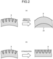
- FIG. 2 is a diagram illustrating an example of a method of measuring an out-of-plane deformation amount.
- a normal force is applied to the steel sheet S to smooth the wrinkles by winding the steel sheet S around the roll 20 or pressing the steel sheet S, and the camber (unilateral elongation) of the steel sheet S in which the wrinkles are smoothed is measured.
- the steel sheet S is straightened in the longitudinal direction (not meandering), and the camber (unilateral elongation) is converted from the height of the wrinkle of the steel sheet S.
- the out-of-plane deformation amount is measured (converted) by the second method.
- shape parameter ⁇ 1 representing unilateral elongation or camber is defined as in the following Formula (17).
- ⁇ 1 3 ⁇ ⁇ 1 1 ⁇ ⁇ l x , y ′ y ′ dy ′ ⁇ 10 5
- the unit of the shape parameter ⁇ 1 is an I-unit.
- y' can be expressed by the following Formula (18).
- y ′ 2 b y
- the shape parameter ⁇ 1 has a proportional relationship with the curvature K 1 .
- FIG. 3 is a diagram illustrating a measurement result of unilateral elongation or camber which is an out-of-plane deformation amount of the steel sheet S measured by the shape measurement device 7 installed on the delivery side of the entry-side looper 5.
- the horizontal axis represents time
- the vertical axis represents the shape parameter ⁇ 1 defined by the above Formulae (17) and (19).
- the shape parameter ⁇ 1 rapidly changes at the joining point.
- there is no unilateral elongation or camber derived from the hot rolling process and in the succeeding material, there is unilateral elongation or camber derived from the hot rolling process, and the size of the unilateral elongation or camber gradually decreases as the tip end is separated.
- the shape measurement device 7 is installed immediately downstream of the steering device 6.
- the shape measurement device 7 is a real-time 3D laser scanner that rotates a plurality of laser beams and measures a distance and a rotation angle between a rotation center and a surface of a steel sheet to measure a position of the surface of the steel sheet as a point cloud.
- the rotation cycle of the laser beam is, for example, 0.1 seconds.
- the surface of the steel sheet can be measured instantaneously, there are advantages that it is possible to perform measurement without depending on the line speed, with vibration resistance, and in a non-contact manner, and thus a large shape can be measured.
- the measurement error is removed by the smoothing thin plate spline method to calculate the steel sheet curved surface W from the point cloud.
- the curvature K 1 is calculated from the above Formula (14) and the steel sheet curved surface W, and the shape parameter ⁇ 1 is further calculated from the above Formula (19).
- the steel sheet S on the entry side of the rolling mill is broken by the cold rolling by the cold rolling mill 11. Since the shape measurement device 7 is installed on the upstream side of the cold rolling mill 11, information on the shape of the steel sheet S on the entry side of the rolling mill can be known before the cold rolling. The risk of the steel sheet S breaking can be predicted by the magnitude of the unilateral elongation or the camber obtained from the information. Therefore, when the unilateral elongation or camber on the entry side of the rolling mill is too large, it is possible to perform an operation so as not to perform rolling in order to prevent breakage of the steel sheet S.
- the shape measurement device 7 measures, as the out-of-plane deformation amount of the steel sheet S, the unilateral elongation or the camber on the entry side of the rolling mill.
- the measured out-of-plane deformation amount (unilateral elongation or camber) exceeds a preset threshold value, the cold rolling is not performed on the steel sheet S by the cold rolling mill 11. However, if rolling is not performed, the portion does not become a product, and thus the yield decreases.
- leveling control will be described with reference to FIG. 4 in order to more actively utilize the information on the shape of the steel sheet S on the entry side of the rolling mill.
- leveling FB control is performed in order to correct the unilateral elongation or the camber of the steel sheet S in the cold rolling mill 11. As illustrated in FIG.
- a first shape meter roll 111a, a second shape meter roll 111b, a third shape meter roll 111c, a fourth shape meter roll 111d, and a fifth shape meter roll 111e are installed on the delivery sides of a first rolling mill 110a, a second rolling mill 110b, a third rolling mill 110c, a fourth rolling mill 110d, and a fifth rolling mill 110e, respectively.
- the first rolling mill 110a, the second rolling mill 110b, the third rolling mill 110c, the fourth rolling mill 110d, and the fifth rolling mill 110e are also simply referred to as a rolling mill 110 unless otherwise distinguished.
- first shape meter roll 111a the second shape meter roll 111b, the third shape meter roll 111c, the fourth shape meter roll 111d, and the fifth shape meter roll 111e are also simply referred to as a shape meter roll 111 unless otherwise distinguished.
- the shape meter roll 111 measures a contact force distribution between the shape meter roll 111 and the steel sheet S, and estimates unilateral elongation or camber, which is an out-of-plane deformation amount of the steel sheet S, from the contact force distribution.
- the measurement method of the shape meter roll 111 has high accuracy, it is necessary to bring the shape meter roll into contact with the steel sheet S. Therefore, it is difficult to measure a large shape defect. Therefore, merely estimating the unilateral elongation or the camber from the contact force distribution measured by the shape meter roll 111 may cause breakage due to the camber stress in rolling by the rolling mill 110.
- the cold rolling mill 11 is provided with a first leveling control device 151a, a second leveling control device 151b, a third leveling control device 151c, a fourth leveling control device 151d, and a fifth leveling control device 151e respectively corresponding to the first rolling mill 110a, the second rolling mill 110b, the third rolling mill 110c, the fourth rolling mill 110d, and the fifth rolling mill 110e.
- the first leveling control device 151a, the second leveling control device 151b, the third leveling control device 151c, the fourth leveling control device 151d, and the fifth leveling control device 151e are also simply referred to as a leveling control device 151 unless otherwise distinguished.
- the leveling control device 151 calculates a leveling target value by multiplying a value obtained by time-integrating the unilateral elongation or the camber on the delivery side of the rolling mill by a gain.
- the leveling target value is equal to the pressing position difference between the left and right bearings of the backup roll of the rolling mill 110, and consequently, the pressing amount difference between one side in the sheet thickness direction and the other side in the sheet thickness direction (the pressing amount difference between the left and right of the steel sheet S) with the center portion of the steel sheet S in the sheet thickness direction as a boundary. Then, the leveling FB control is performed on the corresponding rolling mill 110 so as to obtain the calculated leveling target value.
- the contact force distribution on the shape meter roll 111 on the delivery side of the rolling mill becomes symmetric, and as a result, the unilateral elongation or the camber can be reduced.
- the leveling FB control it is not possible to cope with a sudden disturbance, and it is not sufficient to cope with unilateral elongation or camber as illustrated in FIG. 3 .
- the 5-high rolling mill 110 is provided in the cold rolling mill 11, but the rolling mill 110 to be controlled to the leveling target value may include at least the rolling mill 110 provided most upstream in the conveying direction of the steel sheet S. Therefore, in the cold rolling equipment 1 according to the embodiment, one or more rolling mills 110 including the rolling mill 110 (the first rolling mill 110a) provided on the most upstream side are targets of the leveling FB control.
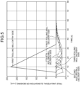
- FIG. 5 is a diagram illustrating transition of true unilateral elongation or camber as a result of a simulation in which a steel sheet S having unilateral elongation or camber is cold rolled.
- FIG. 6 is a diagram illustrating transition of the unilateral elongation or the camber converted from the difference tension as a result of the simulation in which the steel sheet S having the unilateral elongation or the camber is cold rolled.
- the unilateral elongation or the camber on the entry side of the first rolling mill is based on the unilateral elongation or the camber illustrated in FIG. 3 .
- the true unilateral elongation or camber on the delivery side of the first rolling mill is smaller than the true unilateral elongation or camber on the entry side of the first rolling mill. This is considered to be because the rolling phenomenon itself has an action of reducing the unilateral elongation or the camber.
- the magnitude of the true unilateral elongation or camber on the delivery side of the first rolling mill also increases.
- the true unilateral elongation or camber on the delivery side of the first rolling mill illustrated in FIG. 5 is compared with the unilateral elongation or camber converted from the difference tension on the delivery side of the first rolling mill illustrated in FIG. 6 .
- the unilateral elongation or camber converted from the difference tension is different from the true unilateral elongation or camber.
- the both are relatively matched.
- the unilateral elongation or camber converted from the difference tension on the delivery side of the first rolling mill and the unilateral elongation or camber converted from the difference tension in the first shape meter roll 111a illustrated in FIG. 6 relatively coincide with each other.
- the unilateral elongation or camber converted from the difference tension in the first shape meter roll 111a disposed on the delivery side of the first rolling mill 110a does not necessarily coincide with the true unilateral elongation or camber. Therefore, it is not possible to observe true unilateral elongation or camber in the actual machine. Therefore, the results of a simulation in which the steel sheet S having unilateral elongation or camber in the case of performing the leveling FB control is cold rolled are illustrated in FIGS. 7 and 8 .
- FIG. 7 is a diagram illustrating transition of true unilateral elongation or camber as a result of a simulation in which a steel sheet S having unilateral elongation or camber is cold rolled in a case where the leveling FB control is performed.
- FIG. 8 is a diagram illustrating transition of the unilateral elongation or camber converted from the difference tension as a result of the simulation in which the steel sheet S having the unilateral elongation or camber is cold rolled when the leveling FB control is performed.
- the leveling of the first rolling mill 110a to the fifth rolling mill 110e is controlled so as to reduce the magnitude of the difference tension in each of the first shape meter roll 111a to the fifth shape meter roll 111e disposed on the delivery side of each of the first rolling mill 110a to the fifth rolling mill 110e. Therefore, the magnitude of the unilateral elongation or camber converted from the difference tension illustrated in FIG. 8 can be made significantly smaller than the magnitude of the unilateral elongation or camber converted from the difference tension illustrated in FIG. 6 . On the other hand, the magnitude of the true unilateral elongation or camber on the delivery side of the first rolling mill illustrated in FIG.
- FIGS. 9 and 10 the results of performing the leveling FB control so as to reduce the true unilateral elongation or camber on the delivery side of the first rolling mill by simulation are illustrated in FIGS. 9 and 10 .
- FIG. 9 is a diagram illustrating transition of true unilateral elongation or camber as a result of performing the leveling FB control so as to reduce the true unilateral elongation or camber on the delivery side of the first rolling mill by simulation.
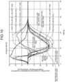
- FIG. 10 is a diagram illustrating transition of the unilateral elongation or camber converted from the difference tension as a result of performing the leveling FB control so as to reduce the true unilateral elongation or camber on the delivery side of the first rolling mill by simulation.
- the leveling FB control in the present embodiment controls the leveling so as to reduce the magnitude of true unilateral elongation or camber on the delivery side of the first rolling mill. Therefore, the magnitude of the true unilateral elongation or camber on the delivery side of the first rolling mill illustrated in FIG. 9 can be made significantly smaller than the magnitude of the true unilateral elongation or camber on the delivery side of the first rolling mill illustrated in FIGS. 5 and 7 . On the other hand, the magnitude of the unilateral elongation or camber converted from the difference tension illustrated in FIG. 10 is larger than the unilateral elongation or camber converted from the difference tension illustrated in FIG. 8 .
- the true unilateral elongation or camber on the delivery side of the first rolling mill cannot be observed, but the unilateral elongation or camber on the entry side of the first rolling mill can be measured. Therefore, by using the simulation, it is possible to calculate the leveling amount that reduces the magnitude of the true unilateral elongation or camber on the delivery side of the first rolling mill from the unilateral elongation or camber on the entry side of the first rolling mill. Even in an actual machine, in principle, if simulation is performed at the time when the unilateral elongation or camber on the entry side of the first rolling mill is found, an appropriate leveling amount can be calculated in advance.
- the leveling FF control is performed on the first rolling mill 110a of the actual machine with the calculated leveling amount. As a result, it is possible to reduce true unilateral elongation or camber on the delivery side of the first rolling mill.
- the appropriate leveling amount can be obtained online by calculating the unilateral elongation or camber on the entry side of the first rolling mill and the appropriate leveling amount in a plurality of cases and performing machine learning so as to output the appropriate leveling amount from the unilateral elongation or camber on the entry side of the first rolling mill.
- a calculation device 150 illustrated in FIG. 4 calculates the leveling amount used for the leveling FF control of the first rolling mill 110a using a value obtained as a result of applying a leveling amount calculation program to the out-of-plane deformation amount (unilateral elongation or camber) on the entry side of the first rolling mill acquired from the shape measurement device 7.
- the leveling amount calculation program to be applied is machine-learned by using each out-of-plane deformation amount of the plurality of steel sheets as an input variable and each leveling amount obtained as a result of physical simulation for each out-of-plane deformation amount as an objective variable.
- the leveling FF control in combination with the leveling FB control instead of using the leveling FF control alone. Therefore, the results of a simulation in which the steel sheet S having unilateral elongation or camber is cold rolled by performing the leveling FF control and the leveling FB control are illustrated in FIGS. 11 and 12 .
- the leveling FF control output and the leveling FB control output are added to each other to be the control output.
- FIG. 11 is a diagram illustrating transition of true unilateral elongation or camber as a result of a simulation in which the steel sheet S having unilateral elongation or camber is cold rolled by performing the leveling FF control and the leveling FB control.
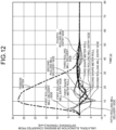
- FIG. 12 is a diagram illustrating transition of the unilateral elongation or camber converted from the difference tension as a result of a simulation in which the steel sheet S having the unilateral elongation or camber is cold rolled by performing the leveling FF control and the leveling FB control.
- the true unilateral elongation or camber on the delivery side of the first rolling mill illustrated in FIG. 11 is smaller than the true unilateral elongation or camber on the delivery side of the first rolling mill illustrated in FIG. 7 , but is larger than the true unilateral elongation or camber on the delivery side of the first rolling mill illustrated in FIG. 9 .
- By adjusting the weighting of the leveling FF control and the leveling FB control it is possible to adjust whether the true unilateral elongation or camber on the delivery side of the first rolling mill approaches the result of the leveling FF control or the result of the leveling FB control.
- the leveling FF control output which is appropriate leveling, is calculated from the calculated unilateral elongation or camber on the entry side of the first rolling mill using the machine learning program.
- the first leveling control device 151a calculates the leveling amount of the first rolling mill 110a using unilateral elongation or camber on the delivery side of the first rolling mill, which is the out-of-plane deformation amount of the steel sheet S measured by the first shape meter roll 111a.
- the first leveling control device 151a performs leveling FB control for controlling the leveling of the first rolling mill 110a based on the calculated leveling amount. Furthermore, the first leveling control device 151a performs tracking of the steel sheet S from the line speed, weights and adds the leveling FF control output and the leveling FB control at the timing when the unilateral elongation or camber measured by the shape measurement device 7 reaches the first rolling mill 110a, and controls the leveling using the added value as a target value. Then, by performing such leveling control, it is possible to suppress the probability of breakage from 2[%] due to defective leveling control to 1[%].
- the present invention can provide a cold rolling method and cold rolling equipment capable of performing cold rolling with high productivity and yield while securing stability of cold rolling even when cold rolling a difficult-to-roll material having a high load and a small sheet thickness before rolling.
Landscapes
- Engineering & Computer Science (AREA)
- Mechanical Engineering (AREA)
- Control Of Metal Rolling (AREA)
- Metal Rolling (AREA)
Abstract
Description
- The present invention relates to a cold rolling method and cold rolling equipment.
- In general, when a rolled material such as a cold-rolled thin steel sheet is cold-rolled, it is desirable to perform cold rolling in a state in which the sheet passing property of the rolled material is stabilized by improving the shape (or flatness) of the rolled material while maintaining good thickness accuracy in the longitudinal direction and the width direction of the rolled material. On the other hand, for the purpose of suppressing fuel consumption by weight reduction and the like, there is an increasing need for a difficult-to-roll material such as a thin hard material having a high load and a thin sheet thickness before rolling. During cold rolling of such a difficult-to-roll material, in order to suppress a rolling load, the difficult-to-roll material is thinned by hot rolling in the preceding process and then sent to the cold rolling process.
- In recent years, many of the control factors of the cold rolling mill are automatically controlled by an actuator mounted on the cold rolling mill. As a method of automatically controlling the shape, shape feedback (FB) control is often used in which a shape meter is installed on the delivery side of the rolling mill, and leveling and bender of the rolling mill are automatically controlled using shape data of the shape meter. However, at the time of cold rolling of the difficult-to-roll material as described above, there is a case where the material is joined to the next coil in a state where the camber of the coil tip and tail end due to the shape defect at the time of hot rolling remains. When the camber or the shape defect sharply fluctuates along the coil longitudinal direction, variations with respect to roll deflection correction represented by a roll gap, leveling, a work roll bender or an intermediate roll shift of a cold rolling mill, and roll expansion by a thermal crown, as well as a rolling load (and an accompanying calculated forward slip or torque), cannot be absorbed by automatic control. For this reason, the shape of the rolled material after cold rolling is often poor, and sheet breakage frequently occurs during cold rolling. A weak point of the FB control is that it cannot cope with sudden fluctuations, and feed-forward (FF) control is also used to compensate for this.
- Patent Literature 1 discloses an FF control method of predicting unilateral elongation or camber of a steel sheet on the entry side of a rolling mill from difference tension measured by a difference tensiometer on the upstream side of the rolling mill, and controlling leveling so as to correct the predicted unilateral elongation or camber. In addition,
Patent Literature 2 discloses a method for suppressing a rollability defect by performing FF control on a bender of a rolling mill on the basis of a twist of steel sheet shape data of a cross-sectional profile meter on the upstream side of the rolling mill and a C-warping height. In addition,Patent Literature 3 discloses a method for suppressing rollability defect by stopping rolling when the twist of the steel sheet shape data of the cross-sectional profile meter on the upstream side of the rolling mill and the C-warping height are out of a predetermined range. -
- Patent Literature 1:
JP 2012-161806 A - Patent Literature 2:
JP 2022-14800 A - Patent Literature 3:
JP 2021-133411 A - In the method disclosed in Patent Literature 1, the difference tension between the stands is measured, and the average unilateral elongation or camber between the stands is predicted from the difference tension.
Therefore, it does not matter if the change in the unilateral elongation or the camber is gentle, but in a case where the change is rapid as in the joint point, the unilateral elongation or the camber predicted from the difference tension and the unilateral elongation or the camber on the delivery side of the rolling mill are different, and thus, it is not possible to perform control well. This is because if the unilateral elongation or camber is too large, the steel sheet cannot be stuck to the roll, and the difference tension cannot be measured by the difference tensiometer. In the methods disclosed inPatent Literature 2 andPatent Literature 3, in order to calculate unilateral elongation or camber of a steel sheet having large unilateral elongation or camber, a cross-sectional shape of the steel sheet is measured to calculate the twist and C-warping height of the cross section of the steel sheet. However, the twist and the C-warping height are only a part of the steel sheet shape information, and it is difficult to calculate accurate unilateral elongation or camber from the cross-sectional shape, so that it is not possible to perform control well. - The present invention has been made in view of the above problems, and an object of the present invention is to provide a cold rolling method and cold rolling equipment capable of performing cold rolling with high productivity and yield while securing stability of cold rolling even when cold rolling a difficult-to-roll material having a high load and a small sheet thickness before rolling.
- To solve the problem and achieve the object, (1) a cold rolling method according to the present invention includes: a calculation step of calculating a leveling amount of a rolling mill using an out-of-plane deformation amount of a steel sheet measured on an upstream side of the rolling mill; a control step of controlling leveling of the rolling mill on a basis of the leveling amount calculated in the calculation step; and a cold rolling step of applying cold rolling to the steel sheet using the rolling mill controlled by the control step.
- (2) Moreover, in the cold rolling method according to above (1), the out-of-plane deformation amount of the steel sheet may be an out-of-plane deformation amount measured on the upstream side of the rolling mill and immediately upstream or immediately downstream of a steering device that changes a conveying direction of the steel sheet.
- (3) Moreover, in the cold rolling method according to above (1) or (2), when the out-of-plane deformation amount of the steel sheet measured on the upstream side of the rolling mill exceeds a threshold value, the cold rolling may not be performed on the steel sheet in the cold rolling step.
- (4) Moreover, in the cold rolling method according to any one of above (1) to (3), in the calculation step, the leveling amount may be calculated using a value obtained as a result of applying a leveling amount calculation program to the out-of-plane deformation amount, and the leveling amount calculation program may be a machine-learned program using each out-of-plane deformation amount of a plurality of steel sheets as an input variable and each leveling amount obtained as a result of physical simulation with respect to each out-of-plane deformation amount as an objective variable.
- (5) Moreover, in the cold rolling method according to any one of above (1) to (4), in the calculation step, the leveling amount may be calculated using an out-of-plane deformation amount of the steel sheet on the upstream side of the rolling mill and an out-of-plane deformation amount of the steel sheet measured on a downstream side of the rolling mill.
- (6) Moreover, a cold rolling equipment according to the present invention includes: a rolling mill that applies cold rolling to a steel sheet; a shape measurement device that is disposed on an upstream side of the rolling mill and measures an out-of-plane deformation amount of the steel sheet; a calculation device that calculates a leveling amount of the rolling mill using the out-of-plane deformation amount of the steel sheet measured by the shape measurement device; and a control device that controls leveling of the rolling mill on a basis of the leveling amount calculated by the calculation device.
- (7) Moreover, the cold rolling equipment according to above (6) may further include a steering device that is disposed on the upstream side of the rolling mill and changes a conveying direction of the steel sheet, wherein the out-of-plane deformation amount of the steel sheet may be an out-of-plane deformation amount measured on the upstream side of the rolling mill and immediately upstream or immediately downstream of the steering device.
- (8) Moreover, in the cold rolling equipment according to above (6) or (7), when the out-of-plane deformation amount of the steel sheet measured on the upstream side of the rolling mill exceeds a threshold value, the rolling mill may not execute the cold rolling on the steel sheet.
- (9) Moreover, in the cold rolling equipment according to any one of above (6) to (8), the calculation device may calculate the leveling amount using a value obtained as a result of applying a leveling amount calculation program to the out-of-plane deformation amount, and the leveling amount calculation program may be a machine-learned program using each out-of-plane deformation amount of a plurality of steel sheets as an input variable and each leveling amount obtained as a result of physical simulation with respect to each out-of-plane deformation amount as an objective variable.
- (10) Moreover, in the cold rolling equipment according to any one of above (6) to (9), the calculation device may calculate the leveling amount using an out-of-plane deformation amount of the steel sheet on the upstream side of the rolling mill and an out-of-plane deformation amount of the steel sheet measured on a downstream side of the rolling mill.
- The cold rolling method and the cold rolling equipment according to the present invention have an effect of being able to perform cold rolling with high productivity and yield while securing stability of cold rolling even when cold rolling a difficult-to-roll material having a high load and a small sheet thickness before rolling.
-
-
FIG. 1 is an overall view illustrating a schematic configuration of a cold rolling line according to an embodiment. -
FIG. 2 is a diagram illustrating an example of a method of measuring an out-of-plane deformation amount. -
FIG. 3 is a diagram illustrating a measurement result of unilateral elongation or camber which is an out-of-plane deformation amount of a steel sheet measured by a shape measurement device installed on a delivery side of an entry-side looper. -
FIG. 4 is an explanatory diagram of leveling control. -
FIG. 5 is a diagram illustrating transition of true unilateral elongation or camber as a result of a simulation in which a steel sheet having unilateral elongation or camber is cold rolled. -
FIG. 6 is a diagram illustrating transition of unilateral elongation or camber converted from difference tension as a result of simulation of cold rolling of a steel sheet having unilateral elongation or camber. -
FIG. 7 is a diagram illustrating transition of true unilateral elongation or camber as a result of a simulation in which a steel sheet having unilateral elongation or camber is cold rolled when leveling FB control is performed. -
FIG. 8 is a diagram illustrating transition of unilateral elongation or camber converted from difference tension as a result of a simulation in which a steel sheet having unilateral elongation or camber is cold rolled when leveling FB control is performed. -
FIG. 9 is a diagram illustrating transition of true unilateral elongation or camber as a result of performing leveling FB control so as to reduce true unilateral elongation or camber on the delivery side of a first rolling mill by simulation. -
FIG. 10 is a diagram illustrating transition of unilateral elongation or camber converted from the difference tension as a result of performing the leveling FB control so as to reduce the true unilateral elongation or camber on the delivery side of the first rolling mill by simulation. -
FIG. 11 is a diagram illustrating transition of true unilateral elongation or camber as a result of simulation in which a steel sheet S having unilateral elongation or camber is cold rolled by performing leveling FF control and leveling FB control. -
FIG. 12 is a diagram illustrating transition of unilateral elongation or camber converted from difference tension as a result of a simulation in which a steel sheet S having unilateral elongation or camber is cold rolled by performing leveling FF control and leveling FB control. Description of Embodiments - Hereinafter, embodiments of a cold rolling method and cold rolling equipment according to the present invention will be described. The cold rolling equipment according to an embodiment includes a rolling mill that applies cold rolling to a steel sheet, a shape measurement device that is disposed on an upstream side of the rolling mill and measures an out-of-plane deformation amount of the steel sheet, a calculation device that calculates a leveling amount of the rolling mill using the out-of-plane deformation amount of the steel sheet measured by the shape measurement device, and a control device that controls the leveling of the rolling mill on the basis of the leveling amount calculated by the calculation device. The cold rolling method applied to the cold rolling equipment according to the embodiment includes a calculation step of calculating the leveling amount of the rolling mill using the out-of-plane deformation amount of the steel sheet measured on the upstream side of the rolling mill, a control step of controlling the leveling of the rolling mill on the basis of the leveling amount calculated in the calculation step, and a cold rolling step of applying cold rolling to the steel sheet using the rolling mill controlled by the control step. Note that the present invention is not limited by the present embodiment.
-
FIG. 1 is an overall view illustrating a schematic configuration of cold rolling equipment 1 according to an embodiment. In the cold rolling equipment 1 according to the embodiment, a pay-off reel 2 for discharging the steel sheet S from the coil is installed at the most upstream portion. In addition, the cold rolling equipment 1 according to the embodiment is provided with awelding machine 3 that joins the tail end of the steel sheet S that has been delivered and the tip end of the steel sheet that has been delivered from the next coil, and anotcher 4 that cuts the steel sheet S in a semi-elliptical shape at the end of the welding line in order to suppress stress concentration. The cold rolling equipment 1 according to the embodiment is provided with an entry-side looper 5 for absorbing a line speed difference between the joining process and the rolling process. Asteering device 6 having CPC meandering control is installed on a delivery side of the entry-side looper 5, and ashape measurement device 7 is installed immediately downstream of thesteering device 6. Theshape measurement device 7 may be disposed immediately upstream of thesteering device 6. In the cold rolling equipment 1 according to the embodiment, adeflector steering roll 8 having CPC meandering control, abridle roll group 9 for applying a tension step between a rolling process and an upstream process thereof, and adeflector steering roll 10 having CPC meandering control immediately downstream of thebridle roll group 9 are installed. In the cold rolling equipment 1, a 5-high continuous cold rollingmill 11 for rolling the steel sheet S is installed. In the cold rolling equipment 1, abridle roll 12 for forming a tension step between a rolling step and a downstream step thereof, a cuttingmachine 13, and atension reel 14 for winding the steel sheet S are installed. - At the tip end and the tail end of the steel sheet S delivered from the pay-
off reel 2, there is a shape defective portion accompanied by unilateral elongation or camber derived from the hot rolling process. In addition, when the steel sheet S is not straight at the time of joining by thewelding machine 3, the steel sheet S is welded in a "chevron" shape, and the unilateral elongation or camber is further increased. When such a shape defective portion is cold-rolled by thecold rolling mill 11, cracking occurs at the width end of the steel sheet S during the rolling process, and breaking occurs from the cracking as a starting point. In addition, when a difference tension between rolling mills (between stands) of thecold rolling mill 11 due to unilateral elongation or camber is applied to the steel sheet S, breaking occurs due to cracking, or breaking occurs even if the steel sheet S is not cracked. The difference tension refers to a tension difference between both ends in the width direction of the steel sheet S detected by a pressure detection unit such as a tensiometer disposed on the delivery side of the rolling mill. - Here, the geometry of the shape of the steel sheet S will be described. A shape defect occurs in the steel sheet S mainly due to unevenness in the width direction of elongation in the longitudinal direction in the rolling process. The shape defect is superposition such as unilateral elongation or camber or an edge wave (center buckle), and the shape defect that most greatly affects breakage during rolling is unilateral elongation or camber. In particular, in the case of a thin sheet, out-of-plane deformation derived from unilateral elongation or camber disappears when the thin sheet is cut, and it is difficult to measure the unilateral elongation or camber. On the other hand, the edge wave (center buckle) can be measured because out-of-plane deformation remains even in the case of a cut sheet.
- When the steel sheet S is a curve, the geometric definition of the curvature κ of the unilateral elongation or the camber can be expressed by the following Formula (1).

- Here, in the above Formula (1), x is a line direction position, v is displacement in the width direction at the width center, w is displacement in the vertical direction at the width center, and ω is a twist angle. Since it is difficult to calculate the above Formula (1), it is considered as a longitudinal average of single elongation or camber. The average curvature K can be defined as the following Formula (2).

- Here, in the above Formula (2), L is a length for averaging. When the above Formula (1) is substituted into the above Formula (2), the average curvature K can be expressed by the following Formula (3).

- The first term on the right side of the above Formula (3) is an amount observed as meandering or skew. The second term on the right side of the above Formula (3) is an amount observed as out-of-plane deformation. From the above Formula (3), it can be seen that even if only meandering is observed, unilateral elongation or camber is not found. If meandering does not occur, the first term on the right side of the above Formula (3) becomes zero, and the average unilateral elongation or camber can be obtained only from the observation amount of out-of-plane deformation. Here, when the twist angle ω is small, the above Formula (3) becomes the following Formula (4).

- Further, the above Formula (4) can be modified to the following Formula (5).

- Here, the observation amount of the out-of-plane deformation of the second term on the right side of the above Formula (5) will be considered. Assuming that the twist angle ω is small, the deflection W of the steel sheet S is expressed by the following Formula (6).

- Here, in the above Formula (6), y is a position in the width direction. The length l of the steel sheet S along the bent curved surface can be expressed by the following Formula (7).

- Further, the elongation difference rate Δεl can be defined as in the following Formula (8).

- Here, in the above Formula (8), l0 is an average length in the width direction, and can be expressed by the following Formula (9).

- Here, in the above Formula (9), b is a sheet width. When the above Formula (6) and the above Formula (7) are substituted into the above Formula (9), the following Formula (10) is established.

- Here, when the deflection w and the twist angle ω are small, the above Formula (10) becomes the following Formula (11).

- Further, when the above Formula (11) is further modified, the following Formula (12) is obtained.

- When the above Formula (6), the above Formula (7), and the above Formula (12) are substituted into the above Formula (8), the elongation difference rate Δεl can be expressed by the following Formula (13).

- The curvature K1 of the average unilateral elongation (average camber) converted from the elongation difference rate Δεl can be defined as in the following Formula (14).

- Then, when the above Formula (13) is substituted into the above Formula (14), the following Formula (15) is obtained.

- The above Formula (15) is the second term on the right side of the above Formula (5), and the above Formula (5) can be expressed as in the following Formula (16).

- From the measured value of the out-of-plane deformation amount or the gradient thereof measured by the
shape measurement device 7, it is possible to calculate the curvature K1 by using the above Formula (14). When there is no meandering of the steel sheet S and the first term on the right side of the above Formula (14) is zero, the curvature K1 of the unique unilateral elongation or camber is the same as the measurable curvature K1. Since it is difficult to measure the first term on the right side of the above Formula (16) related to the meandering of the above Formula (16), it is desirable to measure the out-of-plane deformation amount of the steel sheet S by theshape measurement device 7 at a place where the steel sheet S does not meander. - Here, the out-of-plane deformation amount is one of indices indicating camber and unilateral elongation of the steel sheet S. As a method of measuring the out-of-plane deformation amount, the following two methods are conceivable with reference to
FIG. 2. FIG. 2 is a diagram illustrating an example of a method of measuring an out-of-plane deformation amount. - As a first method, as illustrated in
FIG. 2(a) , a normal force is applied to the steel sheet S to smooth the wrinkles by winding the steel sheet S around theroll 20 or pressing the steel sheet S, and the camber (unilateral elongation) of the steel sheet S in which the wrinkles are smoothed is measured. - As a second method, as illustrated in
FIG. 2(b) , the steel sheet S is straightened in the longitudinal direction (not meandering), and the camber (unilateral elongation) is converted from the height of the wrinkle of the steel sheet S. - In the first method, if the length of the steel sheet S in the longitudinal direction for smoothing wrinkles is short, it is difficult to perform measurement. Therefore, it is desirable to employ the second method, and in the present embodiment, the out-of-plane deformation amount is measured (converted) by the second method.
- In the field of rolling, the shape of the asymmetric component is often expressed by the difference between the right and left sides (shape parameter) of the elongation difference rate distribution. A shape parameter λ1 representing unilateral elongation or camber is defined as in the following Formula (17).

- The unit of the shape parameter λ1 is an I-unit. Here, y' can be expressed by the following Formula (18).

- Then, when the above Formula (18) and the above Formula (14) are substituted into the above Formula (17), the following Formula (19) is obtained.

- As can be seen from the above Formula (19), the shape parameter λ1 has a proportional relationship with the curvature K1.
-
FIG. 3 is a diagram illustrating a measurement result of unilateral elongation or camber which is an out-of-plane deformation amount of the steel sheet S measured by theshape measurement device 7 installed on the delivery side of the entry-side looper 5. InFIG. 3 , the horizontal axis represents time, and the vertical axis represents the shape parameter λ1 defined by the above Formulae (17) and (19). In this case, the shape parameter λ1 rapidly changes at the joining point. In the preceding material, there is no unilateral elongation or camber derived from the hot rolling process, and in the succeeding material, there is unilateral elongation or camber derived from the hot rolling process, and the size of the unilateral elongation or camber gradually decreases as the tip end is separated. - In order to detect the unilateral elongation or the camber by the
shape measurement device 7, it is preferable that the steel sheet S does not meander, and in the present embodiment, theshape measurement device 7 is installed immediately downstream of thesteering device 6. Theshape measurement device 7 is a real-time 3D laser scanner that rotates a plurality of laser beams and measures a distance and a rotation angle between a rotation center and a surface of a steel sheet to measure a position of the surface of the steel sheet as a point cloud. The rotation cycle of the laser beam is, for example, 0.1 seconds. By using the 3D scanner as theshape measurement device 7, theshape measurement device 7 can be installed outside the line with a single sensor, so that there are few installation restrictions and maintenance is simple. In addition, since the surface of the steel sheet can be measured instantaneously, there are advantages that it is possible to perform measurement without depending on the line speed, with vibration resistance, and in a non-contact manner, and thus a large shape can be measured. Since the position of the point cloud has a measurement error and is an irregular point cloud, the measurement error is removed by the smoothing thin plate spline method to calculate the steel sheet curved surface W from the point cloud. Note that, since it takes time to calculate the smoothing thin plate spline method, it is preferable to use, for example, the technique disclosed inJapanese Patent Application Laid-Open No. 2017-49071 - Here, when the unilateral elongation or camber as illustrated in
FIG. 3 is present in the steel sheet S on the entry side of the rolling mill, the steel sheet S is broken by the cold rolling by thecold rolling mill 11. Since theshape measurement device 7 is installed on the upstream side of thecold rolling mill 11, information on the shape of the steel sheet S on the entry side of the rolling mill can be known before the cold rolling. The risk of the steel sheet S breaking can be predicted by the magnitude of the unilateral elongation or the camber obtained from the information. Therefore, when the unilateral elongation or camber on the entry side of the rolling mill is too large, it is possible to perform an operation so as not to perform rolling in order to prevent breakage of the steel sheet S. In the cold rolling equipment 1 according to the embodiment, theshape measurement device 7 measures, as the out-of-plane deformation amount of the steel sheet S, the unilateral elongation or the camber on the entry side of the rolling mill. When the measured out-of-plane deformation amount (unilateral elongation or camber) exceeds a preset threshold value, the cold rolling is not performed on the steel sheet S by thecold rolling mill 11. However, if rolling is not performed, the portion does not become a product, and thus the yield decreases. - Therefore, the leveling control will be described with reference to
FIG. 4 in order to more actively utilize the information on the shape of the steel sheet S on the entry side of the rolling mill. In general, leveling FB control is performed in order to correct the unilateral elongation or the camber of the steel sheet S in thecold rolling mill 11. As illustrated inFIG. 4 , in thecold rolling mill 11, a firstshape meter roll 111a, a secondshape meter roll 111b, a thirdshape meter roll 111c, a fourthshape meter roll 111d, and a fifthshape meter roll 111e are installed on the delivery sides of afirst rolling mill 110a, asecond rolling mill 110b, athird rolling mill 110c, afourth rolling mill 110d, and afifth rolling mill 110e, respectively. In the following description, thefirst rolling mill 110a, thesecond rolling mill 110b, thethird rolling mill 110c, thefourth rolling mill 110d, and thefifth rolling mill 110e are also simply referred to as a rolling mill 110 unless otherwise distinguished. In addition, the firstshape meter roll 111a, the secondshape meter roll 111b, the thirdshape meter roll 111c, the fourthshape meter roll 111d, and the fifthshape meter roll 111e are also simply referred to as a shape meter roll 111 unless otherwise distinguished. - The shape meter roll 111 measures a contact force distribution between the shape meter roll 111 and the steel sheet S, and estimates unilateral elongation or camber, which is an out-of-plane deformation amount of the steel sheet S, from the contact force distribution. Although the measurement method of the shape meter roll 111 has high accuracy, it is necessary to bring the shape meter roll into contact with the steel sheet S. Therefore, it is difficult to measure a large shape defect. Therefore, merely estimating the unilateral elongation or the camber from the contact force distribution measured by the shape meter roll 111 may cause breakage due to the camber stress in rolling by the rolling mill 110.
- The
cold rolling mill 11 is provided with a firstleveling control device 151a, a secondleveling control device 151b, a thirdleveling control device 151c, a fourthleveling control device 151d, and a fifthleveling control device 151e respectively corresponding to thefirst rolling mill 110a, thesecond rolling mill 110b, thethird rolling mill 110c, thefourth rolling mill 110d, and thefifth rolling mill 110e. In the following description, the firstleveling control device 151a, the secondleveling control device 151b, the thirdleveling control device 151c, the fourthleveling control device 151d, and the fifthleveling control device 151e are also simply referred to as a leveling control device 151 unless otherwise distinguished. - The leveling control device 151 calculates a leveling target value by multiplying a value obtained by time-integrating the unilateral elongation or the camber on the delivery side of the rolling mill by a gain. The leveling target value is equal to the pressing position difference between the left and right bearings of the backup roll of the rolling mill 110, and consequently, the pressing amount difference between one side in the sheet thickness direction and the other side in the sheet thickness direction (the pressing amount difference between the left and right of the steel sheet S) with the center portion of the steel sheet S in the sheet thickness direction as a boundary. Then, the leveling FB control is performed on the corresponding rolling mill 110 so as to obtain the calculated leveling target value. By performing such leveling FB control on the rolling mill 110, the contact force distribution on the shape meter roll 111 on the delivery side of the rolling mill becomes symmetric, and as a result, the unilateral elongation or the camber can be reduced. However, as a drawback of the leveling FB control, it is not possible to cope with a sudden disturbance, and it is not sufficient to cope with unilateral elongation or camber as illustrated in
FIG. 3 . - In the cold rolling equipment 1 according to the embodiment, the 5-high rolling mill 110 is provided in the
cold rolling mill 11, but the rolling mill 110 to be controlled to the leveling target value may include at least the rolling mill 110 provided most upstream in the conveying direction of the steel sheet S. Therefore, in the cold rolling equipment 1 according to the embodiment, one or more rolling mills 110 including the rolling mill 110 (thefirst rolling mill 110a) provided on the most upstream side are targets of the leveling FB control. -
FIG. 5 is a diagram illustrating transition of true unilateral elongation or camber as a result of a simulation in which a steel sheet S having unilateral elongation or camber is cold rolled.FIG. 6 is a diagram illustrating transition of the unilateral elongation or the camber converted from the difference tension as a result of the simulation in which the steel sheet S having the unilateral elongation or the camber is cold rolled. The unilateral elongation or the camber on the entry side of the first rolling mill is based on the unilateral elongation or the camber illustrated inFIG. 3 . - As illustrated in
FIG. 5 , the true unilateral elongation or camber on the delivery side of the first rolling mill is smaller than the true unilateral elongation or camber on the entry side of the first rolling mill. This is considered to be because the rolling phenomenon itself has an action of reducing the unilateral elongation or the camber. However, as illustrated inFIG. 5 , in a time (0 to 10 seconds) in which the true unilateral elongation or camber on the entry side of the first rolling mill rapidly changes, the magnitude of the true unilateral elongation or camber on the delivery side of the first rolling mill also increases. - The true unilateral elongation or camber on the delivery side of the first rolling mill illustrated in
FIG. 5 is compared with the unilateral elongation or camber converted from the difference tension on the delivery side of the first rolling mill illustrated inFIG. 6 . Then, it can be seen that, in the time (0 to 10 seconds) in which the true unilateral elongation or camber rapidly changes, the unilateral elongation or camber converted from the difference tension is different from the true unilateral elongation or camber. On the other hand, in a time (10 to 50 seconds) in which the change is relatively gentle, the both are relatively matched. Further, the unilateral elongation or camber converted from the difference tension on the delivery side of the first rolling mill and the unilateral elongation or camber converted from the difference tension in the firstshape meter roll 111a illustrated inFIG. 6 relatively coincide with each other. - From the above, it can be seen that the unilateral elongation or camber converted from the difference tension in the first
shape meter roll 111a disposed on the delivery side of thefirst rolling mill 110a does not necessarily coincide with the true unilateral elongation or camber. Therefore, it is not possible to observe true unilateral elongation or camber in the actual machine. Therefore, the results of a simulation in which the steel sheet S having unilateral elongation or camber in the case of performing the leveling FB control is cold rolled are illustrated inFIGS. 7 and8 . -
FIG. 7 is a diagram illustrating transition of true unilateral elongation or camber as a result of a simulation in which a steel sheet S having unilateral elongation or camber is cold rolled in a case where the leveling FB control is performed.FIG. 8 is a diagram illustrating transition of the unilateral elongation or camber converted from the difference tension as a result of the simulation in which the steel sheet S having the unilateral elongation or camber is cold rolled when the leveling FB control is performed. - In the leveling FB control, the leveling of the
first rolling mill 110a to thefifth rolling mill 110e is controlled so as to reduce the magnitude of the difference tension in each of the firstshape meter roll 111a to the fifthshape meter roll 111e disposed on the delivery side of each of thefirst rolling mill 110a to thefifth rolling mill 110e. Therefore, the magnitude of the unilateral elongation or camber converted from the difference tension illustrated inFIG. 8 can be made significantly smaller than the magnitude of the unilateral elongation or camber converted from the difference tension illustrated inFIG. 6 . On the other hand, the magnitude of the true unilateral elongation or camber on the delivery side of the first rolling mill illustrated inFIG. 7 is smaller at the time (10 to 50 seconds) in which the true unilateral elongation or camber gently changes than the true unilateral elongation or camber on the delivery side of the first rolling mill illustrated inFIG. 5 . However, in the time (0 to 10 seconds) in which the true unilateral elongation or camber rapidly changes, the time is substantially the same, and the leveling FB control cannot be performed. - Originally, it is desired to reduce the magnitude of the true unilateral elongation or camber on the delivery side of the first rolling mill, but it is not possible to observe them in an actual machine. Therefore, the results of performing the leveling FB control so as to reduce the true unilateral elongation or camber on the delivery side of the first rolling mill by simulation are illustrated in
FIGS. 9 and10 . -
FIG. 9 is a diagram illustrating transition of true unilateral elongation or camber as a result of performing the leveling FB control so as to reduce the true unilateral elongation or camber on the delivery side of the first rolling mill by simulation.FIG. 10 is a diagram illustrating transition of the unilateral elongation or camber converted from the difference tension as a result of performing the leveling FB control so as to reduce the true unilateral elongation or camber on the delivery side of the first rolling mill by simulation. - The leveling FB control in the present embodiment controls the leveling so as to reduce the magnitude of true unilateral elongation or camber on the delivery side of the first rolling mill. Therefore, the magnitude of the true unilateral elongation or camber on the delivery side of the first rolling mill illustrated in
FIG. 9 can be made significantly smaller than the magnitude of the true unilateral elongation or camber on the delivery side of the first rolling mill illustrated inFIGS. 5 and7 . On the other hand, the magnitude of the unilateral elongation or camber converted from the difference tension illustrated inFIG. 10 is larger than the unilateral elongation or camber converted from the difference tension illustrated inFIG. 8 . The true unilateral elongation or camber on the delivery side of the first rolling mill cannot be observed, but the unilateral elongation or camber on the entry side of the first rolling mill can be measured. Therefore, by using the simulation, it is possible to calculate the leveling amount that reduces the magnitude of the true unilateral elongation or camber on the delivery side of the first rolling mill from the unilateral elongation or camber on the entry side of the first rolling mill. Even in an actual machine, in principle, if simulation is performed at the time when the unilateral elongation or camber on the entry side of the first rolling mill is found, an appropriate leveling amount can be calculated in advance. Then, at the timing when the unilateral elongation or camber reaches thefirst rolling mill 110a, the leveling FF control is performed on thefirst rolling mill 110a of the actual machine with the calculated leveling amount. As a result, it is possible to reduce true unilateral elongation or camber on the delivery side of the first rolling mill. - Note that the simulation takes a calculation time. Therefore, the appropriate leveling amount can be obtained online by calculating the unilateral elongation or camber on the entry side of the first rolling mill and the appropriate leveling amount in a plurality of cases and performing machine learning so as to output the appropriate leveling amount from the unilateral elongation or camber on the entry side of the first rolling mill.
- For example, a
calculation device 150 illustrated inFIG. 4 calculates the leveling amount used for the leveling FF control of thefirst rolling mill 110a using a value obtained as a result of applying a leveling amount calculation program to the out-of-plane deformation amount (unilateral elongation or camber) on the entry side of the first rolling mill acquired from theshape measurement device 7. In addition, the leveling amount calculation program to be applied is machine-learned by using each out-of-plane deformation amount of the plurality of steel sheets as an input variable and each leveling amount obtained as a result of physical simulation for each out-of-plane deformation amount as an objective variable. - In practice, since there is a difference between the simulation and the actual machine, it is preferable to use the leveling FF control in combination with the leveling FB control instead of using the leveling FF control alone. Therefore, the results of a simulation in which the steel sheet S having unilateral elongation or camber is cold rolled by performing the leveling FF control and the leveling FB control are illustrated in
FIGS. 11 and12 . In thefirst rolling mill 110a, the leveling FF control output and the leveling FB control output are added to each other to be the control output. -
FIG. 11 is a diagram illustrating transition of true unilateral elongation or camber as a result of a simulation in which the steel sheet S having unilateral elongation or camber is cold rolled by performing the leveling FF control and the leveling FB control.FIG. 12 is a diagram illustrating transition of the unilateral elongation or camber converted from the difference tension as a result of a simulation in which the steel sheet S having the unilateral elongation or camber is cold rolled by performing the leveling FF control and the leveling FB control. - The true unilateral elongation or camber on the delivery side of the first rolling mill illustrated in
FIG. 11 is smaller than the true unilateral elongation or camber on the delivery side of the first rolling mill illustrated inFIG. 7 , but is larger than the true unilateral elongation or camber on the delivery side of the first rolling mill illustrated inFIG. 9 . By adjusting the weighting of the leveling FF control and the leveling FB control, it is possible to adjust whether the true unilateral elongation or camber on the delivery side of the first rolling mill approaches the result of the leveling FF control or the result of the leveling FB control. - In the leveling control applied to the cold rolling equipment 1 according to the embodiment, the data processing of the
shape measurement device 7, which is a shape meter disposed on the entry side of thefirst rolling mill 110a, is performed, and the unilateral elongation or camber on the entry side of the first rolling mill is calculated. Then, the leveling FF control output, which is appropriate leveling, is calculated from the calculated unilateral elongation or camber on the entry side of the first rolling mill using the machine learning program. The firstleveling control device 151a calculates the leveling amount of thefirst rolling mill 110a using unilateral elongation or camber on the delivery side of the first rolling mill, which is the out-of-plane deformation amount of the steel sheet S measured by the firstshape meter roll 111a. Then, the firstleveling control device 151a performs leveling FB control for controlling the leveling of thefirst rolling mill 110a based on the calculated leveling amount. Furthermore, the firstleveling control device 151a performs tracking of the steel sheet S from the line speed, weights and adds the leveling FF control output and the leveling FB control at the timing when the unilateral elongation or camber measured by theshape measurement device 7 reaches thefirst rolling mill 110a, and controls the leveling using the added value as a target value. Then, by performing such leveling control, it is possible to suppress the probability of breakage from 2[%] due to defective leveling control to 1[%]. - As described above, the present invention can provide a cold rolling method and cold rolling equipment capable of performing cold rolling with high productivity and yield while securing stability of cold rolling even when cold rolling a difficult-to-roll material having a high load and a small sheet thickness before rolling.
-
- 1 COLD ROLLING EQUIPMENT
- 2 PAY-OFF REEL
- 3 WELDING MACHINE
- 4 NOTCHER
- 5 ENTRY-SIDE LOOPER
- 6 STEERING DEVICE
- 7 SHAPE MEASUREMENT DEVICE
- 8 DEFLECTOR STEERING ROLL
- 9 BRIDLE ROLL GROUP
- 10 DEFLECTOR STEERING ROLL
- 11 COLD ROLLING MILL
- 12 BRIDLE ROLL
- 13 CUTTING MACHINE
- 14 TENSION REEL
- 110 ROLLING MILL
- 110a FIRST ROLLING MILL
- 110b SECOND ROLLING MILL
- 110c THIRD ROLLING MILL
- 110d FOURTH ROLLING MILL
- 110e FIFTH ROLLING MILL
- 111 SHAPE METER ROLL
- 111a FIRST SHAPE METER ROLL
- 111b SECOND SHAPE METER ROLL
- 111c THIRD SHAPE METER ROLL
- 111d FOURTH SHAPE METER ROLL
- 111e FIFTH SHAPE METER ROLL
- 150 CALCULATION DEVICE
- 151 LEVELING CONTROL DEVICE
- 151a FIRST LEVELING CONTROL DEVICE
- 151b SECOND LEVELING CONTROL DEVICE
- 151c THIRD LEVELING CONTROL DEVICE
- 151d FOURTH LEVELING CONTROL DEVICE
- 151e FIFTH LEVELING CONTROL DEVICE
Claims (18)
- A cold rolling method comprising:a calculation step of calculating a leveling amount of a rolling mill using an out-of-plane deformation amount of a steel sheet measured on an upstream side of the rolling mill;a control step of controlling leveling of the rolling mill on a basis of the leveling amount calculated in the calculation step; anda cold rolling step of applying cold rolling to the steel sheet using the rolling mill controlled by the control step.
- The cold rolling method according to claim 1, wherein the out-of-plane deformation amount of the steel sheet is an out-of-plane deformation amount measured on the upstream side of the rolling mill and immediately upstream or immediately downstream of a steering device that changes a conveying direction of the steel sheet.
- The cold rolling method according to claim 1 or 2, wherein, when the out-of-plane deformation amount of the steel sheet measured on the upstream side of the rolling mill exceeds a threshold value, the cold rolling is not performed on the steel sheet in the cold rolling step.
- The cold rolling method according to claim 1 or 2, whereinin the calculation step,the leveling amount is calculated using a value obtained as a result of applying a leveling amount calculation program to the out-of-plane deformation amount, andthe leveling amount calculation program is a machine-learned program using each out-of-plane deformation amount of a plurality of steel sheets as an input variable and each leveling amount obtained as a result of physical simulation with respect to each out-of-plane deformation amount as an objective variable.
- The cold rolling method according to claim 3, whereinin the calculation step,the leveling amount is calculated using a value obtained as a result of applying a leveling amount calculation program to an out-of-plane deformation amount of the steel sheet, andthe leveling amount calculation program is a machine-learned program using each out-of-plane deformation amount of a plurality of steel sheets as an input variable and each leveling amount obtained as a result of physical simulation with respect to each out-of-plane deformation amount as an objective variable.
- The cold rolling method according to claim 1 or 2, whereinin the calculation step,the leveling amount is calculated using an out-of-plane deformation amount of the steel sheet on the upstream side of the rolling mill and an out-of-plane deformation amount of the steel sheet measured on a downstream side of the rolling mill.
- The cold rolling method according to claim 3, whereinin the calculation step,the leveling amount is calculated using an out-of-plane deformation amount of the steel sheet on the upstream side of the rolling mill and an out-of-plane deformation amount of the steel sheet measured on a downstream side of the rolling mill.
- The cold rolling method according to claim 4, whereinin the calculation step,the leveling amount is calculated using an out-of-plane deformation amount of the steel sheet on the upstream side of the rolling mill and an out-of-plane deformation amount of the steel sheet measured on a downstream side of the rolling mill.
- The cold rolling method according to claim 5, whereinin the calculation step,the leveling amount is calculated using an out-of-plane deformation amount of the steel sheet on the upstream side of the rolling mill and an out-of-plane deformation amount of the steel sheet measured on a downstream side of the rolling mill.
- A cold rolling equipment comprising:a rolling mill that applies cold rolling to a steel sheet;a shape measurement device that is disposed on an upstream side of the rolling mill and measures an out-of-plane deformation amount of the steel sheet;a calculation device that calculates a leveling amount of the rolling mill using the out-of-plane deformation amount of the steel sheet measured by the shape measurement device; anda control device that controls leveling of the rolling mill on a basis of the leveling amount calculated by the calculation device.
- The cold rolling equipment according to claim 10, further comprisinga steering device that is disposed on the upstream side of the rolling mill and changes a conveying direction of the steel sheet, whereinthe out-of-plane deformation amount of the steel sheet is an out-of-plane deformation amount measured on the upstream side of the rolling mill and immediately upstream or immediately downstream of the steering device.
- The cold rolling equipment according to claim 10 or 11, wherein, when the out-of-plane deformation amount of the steel sheet measured on the upstream side of the rolling mill exceeds a threshold value, the rolling mill does not execute the cold rolling on the steel sheet.
- The cold rolling equipment according to claim 10 or 11, whereinthe calculation device calculates the leveling amount using a value obtained as a result of applying a leveling amount calculation program to the out-of-plane deformation amount, andthe leveling amount calculation program is a machine-learned program using each out-of-plane deformation amount of a plurality of steel sheets as an input variable and each leveling amount obtained as a result of physical simulation with respect to each out-of-plane deformation amount as an objective variable.
- The cold rolling equipment according to claim 12, whereinthe calculation device calculates the leveling amount using a value obtained as a result of applying a leveling amount calculation program to the out-of-plane deformation amount, andthe leveling amount calculation program is a machine-learned program using each out-of-plane deformation amount of a plurality of steel sheets as an input variable and each leveling amount obtained as a result of physical simulation with respect to each out-of-plane deformation amount as an objective variable.
- The cold rolling equipment according to claim 10 or 11, wherein the calculation device calculates the leveling amount using an out-of-plane deformation amount of the steel sheet on the upstream side of the rolling mill and an out-of-plane deformation amount of the steel sheet measured on a downstream side of the rolling mill.
- The cold rolling equipment according to claim 12, wherein the calculation device calculates the leveling amount using an out-of-plane deformation amount of the steel sheet on the upstream side of the rolling mill and an out-of-plane deformation amount of the steel sheet measured on a downstream side of the rolling mill.
- The cold rolling equipment according to claim 13, wherein the calculation device calculates the leveling amount using an out-of-plane deformation amount of the steel sheet on the upstream side of the rolling mill and an out-of-plane deformation amount of the steel sheet measured on a downstream side of the rolling mill.
- The cold rolling equipment according to claim 14, wherein the calculation device calculates the leveling amount using an out-of-plane deformation amount of the steel sheet on the upstream side of the rolling mill and an out-of-plane deformation amount of the steel sheet measured on a downstream side of the rolling mill.
Applications Claiming Priority (2)
| Application Number | Priority Date | Filing Date | Title |
|---|---|---|---|
| JP2022134722A JP7841389B2 (en) | 2022-08-26 | 2022-08-26 | Cold rolling method and cold rolling equipment |
| PCT/JP2023/026602 WO2024042936A1 (en) | 2022-08-26 | 2023-07-20 | Cold-rolling method and cold-rolling equipment |
Publications (2)
| Publication Number | Publication Date |
|---|---|
| EP4549041A1 true EP4549041A1 (en) | 2025-05-07 |
| EP4549041A4 EP4549041A4 (en) | 2025-11-05 |
Family
ID=90013163
Family Applications (1)
| Application Number | Title | Priority Date | Filing Date |
|---|---|---|---|
| EP23857052.7A Pending EP4549041A4 (en) | 2022-08-26 | 2023-07-20 | COLD ROLLING PROCESS AND COLD ROLLING EQUIPMENT |
Country Status (4)
| Country | Link |
|---|---|
| US (1) | US20260034576A1 (en) |
| EP (1) | EP4549041A4 (en) |
| JP (1) | JP7841389B2 (en) |
| WO (1) | WO2024042936A1 (en) |
Family Cites Families (11)
| Publication number | Priority date | Publication date | Assignee | Title |
|---|---|---|---|---|
| JPS6268620A (en) * | 1985-09-24 | 1987-03-28 | Nippon Kokan Kk <Nkk> | Rolling control method of cold rolling mill |
| JPH07132310A (en) * | 1993-11-10 | 1995-05-23 | Mitsubishi Heavy Ind Ltd | Rolling method |
| JP2001343223A (en) | 1999-11-08 | 2001-12-14 | Sumitomo Metal Ind Ltd | Band-shaped body quality measuring method, camber suppressing method, band-shaped body quality measuring device, rolling device and trim device |
| JP3844280B2 (en) | 2000-10-25 | 2006-11-08 | 新日本製鐵株式会社 | Reduction leveling setting method in sheet rolling |
| JP2008100245A (en) | 2006-10-18 | 2008-05-01 | Nippon Steel Corp | Apparatus and method for cooling hot-rolled wire rod |
| JP5618210B2 (en) | 2011-02-04 | 2014-11-05 | 新日鐵住金株式会社 | Outlet shape control method in cold rolling mill |
| KR101428306B1 (en) * | 2012-12-21 | 2014-08-07 | 주식회사 포스코 | System and method for controlling strip deviation and hot rolling apparatus |
| JP6360465B2 (en) | 2015-08-31 | 2018-07-18 | エスペック株式会社 | Environmental test equipment and test equipment |
| KR101767783B1 (en) * | 2015-12-24 | 2017-08-14 | 주식회사 포스코 | Apparatus and method for maintaining flatness of rolling material |
| JP2021133411A (en) | 2020-02-28 | 2021-09-13 | Jfeスチール株式会社 | Rolling control method, rolling control device, and production method for metal strip |
| JP7226402B2 (en) | 2020-07-07 | 2023-02-21 | Jfeスチール株式会社 | Metal strip rolling control method, rolling control device, and manufacturing method |
-
2022
- 2022-08-26 JP JP2022134722A patent/JP7841389B2/en active Active
-
2023
- 2023-07-20 WO PCT/JP2023/026602 patent/WO2024042936A1/en not_active Ceased
- 2023-07-20 US US19/100,339 patent/US20260034576A1/en active Pending
- 2023-07-20 EP EP23857052.7A patent/EP4549041A4/en active Pending
Also Published As
| Publication number | Publication date |
|---|---|
| US20260034576A1 (en) | 2026-02-05 |
| EP4549041A4 (en) | 2025-11-05 |
| JP7841389B2 (en) | 2026-04-07 |
| JP2024031268A (en) | 2024-03-07 |
| WO2024042936A1 (en) | 2024-02-29 |
Similar Documents
| Publication | Publication Date | Title |
|---|---|---|
| US5720196A (en) | Hot-rolling method of steel piece joint during continuous hot-rolling | |
| EP0621087B1 (en) | Rolling mill and method | |
| EP2623221B2 (en) | Manufacturing device and manufacturing method for hot-rolled steel strip | |
| EP2737963B1 (en) | Distortion calculation method and rolling system | |
| US5231858A (en) | Method of controlling edge drop in cold rolling of steel | |
| JP7226402B2 (en) | Metal strip rolling control method, rolling control device, and manufacturing method | |
| JP6028871B2 (en) | Thickness control device for rolling mill | |
| JP5239728B2 (en) | Rolling method and rolling apparatus for metal sheet | |
| CN104321151A (en) | Method for processing rolling stock and rolling mill | |
| JP6330734B2 (en) | Steel plate cutting position setting device and steel plate manufacturing method | |
| JP6620777B2 (en) | Leveling setting method for rolling mill and leveling setting apparatus for rolling mill | |
| JP5811051B2 (en) | Method for cold rolling metal plate and method for producing metal plate | |
| JP2008272783A (en) | Skin pass rolling shape control method | |
| JP2013111592A (en) | Method of rolling steel strip | |
| US20260034576A1 (en) | Cold rolling method and cold rolling equipment | |
| JP4878485B2 (en) | Cold continuous rolling equipment | |
| JP4818890B2 (en) | Thickness control method in cold tandem rolling | |
| JP4268582B2 (en) | Plate thickness control method and plate thickness / shape non-interference control method | |
| JP4267609B2 (en) | Rolling method and rolling apparatus for metal sheet | |
| JP6743835B2 (en) | Method for rolling shaped steel and method for adjusting leveling amount in rolling shaped steel | |
| JP6348303B2 (en) | Method and apparatus for rolling hot rolled steel strip | |
| JP7205459B2 (en) | Method for detecting shape defects in steel sheet pile rolling and method for manufacturing steel sheet piles | |
| JP7685721B2 (en) | Control and setting method of plate wedge in hot reversible plate rolling | |
| JP7067541B2 (en) | Rolling mill control method and control device | |
| US20250187059A1 (en) | Meandering control method, meandering control apparatus, and manufacturing method for steel sheet |
Legal Events
| Date | Code | Title | Description |
|---|---|---|---|
| STAA | Information on the status of an ep patent application or granted ep patent |
Free format text: STATUS: THE INTERNATIONAL PUBLICATION HAS BEEN MADE |
|
| PUAI | Public reference made under article 153(3) epc to a published international application that has entered the european phase |
Free format text: ORIGINAL CODE: 0009012 |
|
| STAA | Information on the status of an ep patent application or granted ep patent |
Free format text: STATUS: REQUEST FOR EXAMINATION WAS MADE |
|
| 17P | Request for examination filed |
Effective date: 20250130 |
|
| AK | Designated contracting states |
Kind code of ref document: A1 Designated state(s): AL AT BE BG CH CY CZ DE DK EE ES FI FR GB GR HR HU IE IS IT LI LT LU LV MC ME MK MT NL NO PL PT RO RS SE SI SK SM TR |
|
| A4 | Supplementary search report drawn up and despatched |
Effective date: 20251006 |
|
| RIC1 | Information provided on ipc code assigned before grant |
Ipc: B21B 37/58 20060101AFI20250929BHEP Ipc: B21B 37/68 20060101ALI20250929BHEP Ipc: B21B 38/02 20060101ALI20250929BHEP Ipc: B21C 51/00 20060101ALI20250929BHEP Ipc: B21B 37/28 20060101ALN20250929BHEP Ipc: B21B 1/28 20060101ALN20250929BHEP Ipc: B21B 1/22 20060101ALN20250929BHEP |
|
| DAV | Request for validation of the european patent (deleted) | ||
| DAX | Request for extension of the european patent (deleted) |