EP4546624A1 - Laminated iron core manufacturing method, manufacturing device, laminated iron core, and roating electric machine - Google Patents
Laminated iron core manufacturing method, manufacturing device, laminated iron core, and roating electric machine Download PDFInfo
- Publication number
- EP4546624A1 EP4546624A1 EP23862904.2A EP23862904A EP4546624A1 EP 4546624 A1 EP4546624 A1 EP 4546624A1 EP 23862904 A EP23862904 A EP 23862904A EP 4546624 A1 EP4546624 A1 EP 4546624A1
- Authority
- EP
- European Patent Office
- Prior art keywords
- iron core
- unit iron
- laminated
- unit
- adhesive
- Prior art date
- Legal status (The legal status is an assumption and is not a legal conclusion. Google has not performed a legal analysis and makes no representation as to the accuracy of the status listed.)
- Pending
Links
Images

Classifications
-
- B—PERFORMING OPERATIONS; TRANSPORTING
- B21—MECHANICAL METAL-WORKING WITHOUT ESSENTIALLY REMOVING MATERIAL; PUNCHING METAL
- B21D—WORKING OR PROCESSING OF SHEET METAL OR METAL TUBES, RODS OR PROFILES WITHOUT ESSENTIALLY REMOVING MATERIAL; PUNCHING METAL
- B21D28/00—Shaping by press-cutting; Perforating
- B21D28/02—Punching blanks or articles with or without obtaining scrap; Notching
-
- H—ELECTRICITY
- H02—GENERATION; CONVERSION OR DISTRIBUTION OF ELECTRIC POWER
- H02K—DYNAMO-ELECTRIC MACHINES
- H02K15/00—Processes or apparatus specially adapted for manufacturing, assembling, maintaining or repairing of dynamo-electric machines
- H02K15/02—Processes or apparatus specially adapted for manufacturing, assembling, maintaining or repairing of dynamo-electric machines of stator or rotor bodies
- H02K15/021—Magnetic cores
- H02K15/0273—Laminating the cores
-
- B—PERFORMING OPERATIONS; TRANSPORTING
- B32—LAYERED PRODUCTS
- B32B—LAYERED PRODUCTS, i.e. PRODUCTS BUILT-UP OF STRATA OF FLAT OR NON-FLAT, e.g. CELLULAR OR HONEYCOMB, FORM
- B32B37/00—Methods or apparatus for laminating, e.g. by curing or by ultrasonic bonding
- B32B37/12—Methods or apparatus for laminating, e.g. by curing or by ultrasonic bonding characterised by using adhesives
- B32B37/1207—Heat-activated adhesive
-
- H—ELECTRICITY
- H01—ELECTRIC ELEMENTS
- H01F—MAGNETS; INDUCTANCES; TRANSFORMERS; SELECTION OF MATERIALS FOR THEIR MAGNETIC PROPERTIES
- H01F3/00—Cores, Yokes, or armatures
- H01F3/02—Cores, Yokes, or armatures made from sheets
-
- H—ELECTRICITY
- H01—ELECTRIC ELEMENTS
- H01F—MAGNETS; INDUCTANCES; TRANSFORMERS; SELECTION OF MATERIALS FOR THEIR MAGNETIC PROPERTIES
- H01F41/00—Apparatus or processes specially adapted for manufacturing or assembling magnets, inductances or transformers; Apparatus or processes specially adapted for manufacturing materials characterised by their magnetic properties
- H01F41/02—Apparatus or processes specially adapted for manufacturing or assembling magnets, inductances or transformers; Apparatus or processes specially adapted for manufacturing materials characterised by their magnetic properties for manufacturing cores, coils, or magnets
-
- H—ELECTRICITY
- H01—ELECTRIC ELEMENTS
- H01F—MAGNETS; INDUCTANCES; TRANSFORMERS; SELECTION OF MATERIALS FOR THEIR MAGNETIC PROPERTIES
- H01F41/00—Apparatus or processes specially adapted for manufacturing or assembling magnets, inductances or transformers; Apparatus or processes specially adapted for manufacturing materials characterised by their magnetic properties
- H01F41/02—Apparatus or processes specially adapted for manufacturing or assembling magnets, inductances or transformers; Apparatus or processes specially adapted for manufacturing materials characterised by their magnetic properties for manufacturing cores, coils, or magnets
- H01F41/0206—Manufacturing of magnetic cores by mechanical means
- H01F41/0233—Manufacturing of magnetic circuits made from sheets
-
- H—ELECTRICITY
- H02—GENERATION; CONVERSION OR DISTRIBUTION OF ELECTRIC POWER
- H02K—DYNAMO-ELECTRIC MACHINES
- H02K15/00—Processes or apparatus specially adapted for manufacturing, assembling, maintaining or repairing of dynamo-electric machines
- H02K15/02—Processes or apparatus specially adapted for manufacturing, assembling, maintaining or repairing of dynamo-electric machines of stator or rotor bodies
- H02K15/021—Magnetic cores
-
- H—ELECTRICITY
- H02—GENERATION; CONVERSION OR DISTRIBUTION OF ELECTRIC POWER
- H02K—DYNAMO-ELECTRIC MACHINES
- H02K15/00—Processes or apparatus specially adapted for manufacturing, assembling, maintaining or repairing of dynamo-electric machines
- H02K15/12—Impregnating, moulding insulation, heating or drying of windings, stators, rotors or machines
-
- H—ELECTRICITY
- H02—GENERATION; CONVERSION OR DISTRIBUTION OF ELECTRIC POWER
- H02K—DYNAMO-ELECTRIC MACHINES
- H02K15/00—Processes or apparatus specially adapted for manufacturing, assembling, maintaining or repairing of dynamo-electric machines
- H02K15/12—Impregnating, moulding insulation, heating or drying of windings, stators, rotors or machines
- H02K15/121—Impregnating, moulding insulation, heating or drying of windings, stators, rotors or machines of cores
-
- H—ELECTRICITY
- H02—GENERATION; CONVERSION OR DISTRIBUTION OF ELECTRIC POWER
- H02K—DYNAMO-ELECTRIC MACHINES
- H02K2213/00—Specific aspects, not otherwise provided for and not covered by codes H02K2201/00 - H02K2211/00
- H02K2213/03—Machines characterised by numerical values, ranges, mathematical expressions or similar information
-
- H—ELECTRICITY
- H02—GENERATION; CONVERSION OR DISTRIBUTION OF ELECTRIC POWER
- H02K—DYNAMO-ELECTRIC MACHINES
- H02K2215/00—Specific aspects not provided for in other groups of this subclass relating to methods or apparatus specially adapted for manufacturing, assembling, maintaining or repairing of dynamo-electric machines
Definitions
- the present invention relates to a manufacturing method of a laminated iron core, a manufacturing apparatus of a laminated iron core, a laminated iron core, and a rotary electric machine.
- the laminated iron core is an iron core obtained by laminating thin steel sheets whose surfaces are subjected to insulation treatment, and exhibits an effect of reducing a loss caused by an eddy current.
- Patent Literature 1 discloses a laminated iron core in which lamination surfaces of unit iron cores are partially fixed at the lamination surfaces. Since the fixing portions are partially provided, it is possible to improve a core loss property.
- Patent Literature 2 discloses that, when manufacturing a core by laminating electrical steel sheets each having a coating that exhibits adhesive ability when its surface is heated, provided to a surface thereof, mainly the coatings are heated by a local heating unit after the electrical steel sheets are worked and right before they are laminated, to make the adhesive ability of the coatings to be exhibited, thereby making the laminated electrical steel sheets to be entirely or partially adhered to each other to form the integrated core.
- a core material punched by a press machine is conveyed to a heating position at which heating is performed by an infrared heating machine, in a state of being magnetically attracted to a cylinder of the press machine, and then conveyed to a lamination position.
- the core material is heated in the state of being magnetically attracted to the cylinder of the press machine, when the coating is formed on the entire surface of the core material, there is a possibility that the core material is adhered to the cylinder of the press machine. Accordingly, there is a chance that the core material cannot be properly laminated at the lamination position, and further, a repair of the press machine is sometimes required, and based on that point as well, it cannot be said that it is efficient.
- the present invention has been made in view of the problems as described above, and an object thereof is to increase efficiency of manufacture of a laminated iron core.
- a manufacturing method of a laminated iron core of the present invention is characterized in that it includes: a step of pressing, with a die, an electrical steel sheet having a coating containing an adhesive that exhibits adhesive ability through heating, provided to a sheet surface thereof, to obtain a unit iron core; and a step of laminating the unit iron cores pressed with the die, and heating the sheet surface of the unit iron core of an uppermost layer at a plurality of partial regions to make the unit iron core of the uppermost layer to be partially adhered to the unit iron core of a lower layer thereof at a plurality of regions.
- a manufacturing apparatus of a laminated iron core of the present invention is characterized in that it includes: a progressive die that presses an electrical steel sheet having a coating containing an adhesive that exhibits adhesive ability through heating, provided to a sheet surface thereof, to obtain a unit iron core; a lamination space in which the unit iron cores after being subjected to a final pressing step in the progressive die are laminated; and a heating unit that is disposed at an upper part of the lamination space and that heats the sheet surface of the unit iron core of an uppermost layer laminated in the lamination space, at a plurality of partial regions.
- a laminated iron core of the present invention is characterized in that it is manufactured through a step of pressing, with a die, an electrical steel sheet having a coating containing an adhesive that exhibits adhesive ability through heating, provided to a sheet surface thereof, to obtain a unit iron core, and a step of laminating the unit iron cores pressed with the die, and heating the sheet surface of the unit iron core of an uppermost layer at a plurality of partial regions to make the unit iron core of the uppermost layer to be partially adhered to the unit iron core of a lower layer thereof at a plurality of regions.
- a rotary electric machine of the present invention is characterized in that it includes the laminated iron core.
- the laminated iron core is an iron core obtained by laminating thin steel sheets whose surfaces are subjected to insulation treatment (referred to as "unit iron cores" in the present application).
- a manufacturing apparatus of a laminated iron core includes a progressive die 2 that presses an electrical steel sheet to obtain a unit iron core 1, and a lamination space 3 in which the unit iron cores 1 after being subjected to a final pressing step in the progressive die 2 are laminated.
- the progressive die 2 is a die in which a plurality of pressing steps can be performed, and pressing is performed in sequence while automatically feeding a material to the next step every one shot, as indicated by an arrow mark A in the drawings. Accordingly, it is possible to punch the electrical steel sheet little by little to form the unit iron core 1 having a complicated shape.
- the unit iron core 1 after being subjected to the final pressing step in the progressive die 2 has a thin disk shape punched into a predetermined shape (for example, a ring shape having predetermined outside diameter and inside diameter) (refer to Patent Literature 1, and so on).
- a coating containing an adhesive that exhibits adhesive ability through heating is performed on the electrical steel sheet to be the material of the unit iron core 1, and thus a coating containing the adhesive is provided to the electrical steel sheet, at the stage where the electrical steel sheet is put in the progressive die 2. It is only required to design that the coating containing the adhesive is already provided to the electrical steel sheet wound in a state of coil, shipped from a manufacturer, for example.
- an insulating coating is generally provided to a sheet surface of an electrical steel sheet.
- the coating containing the adhesive may also be this insulating coating in which the adhesive is contained.
- a coating containing the adhesive may also be provided, separately from the insulating coating.
- the coating containing the adhesive includes a coating formed only of the adhesive, and it may also be formed by coating the adhesive onto the insulating coating, for example. Note that the coating containing the adhesive may also be formed by partially coating the adhesive onto the insulating coating.
- the coating containing the adhesive is preferably provided to a front surface and a rear surface being two sheet surfaces of the unit iron core 1. This is because, since there exist the coatings on two sheet surfaces that face each other when the unit iron cores 1 are laminated, the unit iron cores 1 can be adhered to each other more securely. However, it is only required that the coating exists on an entire sheet surface of at least one of the two sheet surfaces that face each other when the unit iron cores 1 are laminated. Therefore, the coating may also be formed only on one sheet surface out of the two sheet surfaces of the unit iron core 1.
- the coating is preferably formed so as to cover the entire area of the sheet surface of the unit iron core 1, but it may also be formed on an area of 50% or more of the entire area of the sheet surface of the unit iron core 1, and it may also be formed on an area of 70% or more, or 90% or more of the entire area.
- the coating changes, when it exhibits the adhesive ability, from a state where an adherend (the unit iron core 1, in the present embodiment) cannot be adhered to the coating to a state where the adherend can be adhered to the coating. Therefore, the state of the coating changes, through heating, from a state where the coating cannot be adhered to the adherend to a state where the coating can be adhered to the adherend. It is possible to check whether or not the adhesive ability is exhibited, by the following method, for example.
- the steel sheet temperature is set to be equal to or more than a temperature that is previously determined as a temperature at which the coating exhibits the adhesive ability.
- the two electrical steel sheets adhered as above, are used as a test piece.
- Shearing tensile strength of the test piece is measured under a condition including an atmospheric temperature of 25°C, and a tensile rate of 3 mm/minute.
- the electrical steel sheet is collected from the laminated iron core, and the collected electrical steel sheet is used to produce a test piece having a configuration same as that of the above-described test piece.
- the adhesive strength of the test piece is 2.5 MPa or more, it can be determined that the adhesive ability is exhibited in the laminated iron core. Note that when the adhesive strength of the test piece is 2.5 MPa or more, this corresponds to the fact that the adhesive strength of the electrical steel sheet in the laminated iron core is 2.5 MPa or more.
- the adhesive contained in the coating is not limited to a specific adhesive.
- various kinds of adhesive such as an acrylic resin adhesive, a cyanoacrylate-based adhesive, an epoxy resin adhesive, a polyester adhesive, a polyurethane adhesive, a melamine resin adhesive, and a phenol resin adhesive, may also be used.
- a thermosetting organic resin adhesive whose chemical reaction proceeds through heating.
- an adhesive containing one kind or two kinds or more of resins such as an epoxy resin, a phenol resin, a urethane resin, and a melamine resin, as a main component, may also be used.
- thermosetting property thereto.
- inorganic adhesive in which a dehydration condensation reaction proceeds through heating to cause curing.
- the adhesive contained in the coating may also be an anaerobic adhesive.
- the adhesive contained in the coating exhibits the adhesive ability through heating and blocking of air. Therefore, it is designed that when the coating and the adherend are adhered to each other, a space is prevented from being generated between the coating and the adherend.
- an adhesive layer is formed on the coating such as the insulating coating, and then heating and pressing of the coating and the adhesive layer are performed, to thereby form the coating containing the adhesive.
- the lamination space 3 is arranged so as to be adjacent to a position of the final pressing step in the progressive die 2.
- the lamination space 3 has a bottom surface 3a at a position lower than a conveyance path 2a of the progressive die 2, for example, and it is configured that the unit iron cores 1 after being subjected to the final pressing step are dropped via a not-illustrated guide, to be laminated one after another.
- the unit iron cores 1 subjected to the final pressing step in the progressive die 2 and then conveyed in sequence to the lamination space 3 are in the same direction, so that the unit iron cores 1 are laminated by being dropped in the lamination space 3 without changing the direction.
- a plurality of laser oscillators 4 are disposed.
- the respective laser oscillators 4 irradiate partial regions of the unit iron core 1 of an uppermost layer laminated in the lamination space 3 (a unit iron core 1a in Fig. 1A , and a unit iron core 1c in Fig. 1C ) with laser beams, to thereby partially heat the unit iron core 1.
- the partial heating means heating of a partial region of a sheet surface of the unit iron core 1. Concretely, it is possible to define that a region physically irradiated with the laser beam on the unit iron core 1 is a partial region of the entire area of the sheet surface of the unit iron core 1.
- These plurality of laser oscillators 4 function as a heating unit that heats the sheet surface of the unit iron core 1 at a plurality of partial regions. Two or more of regions out of these plurality of partial regions are set to be at positions separated from each other. Note that the present embodiment exemplifies a case where all of a plurality of partial regions to be heated are at positions separated from each other. However, the plurality of partial regions to be heated may also include two or more of regions that are not separated from each other.
- the heating means that the unit iron core 1 is heated to a temperature equal to or more than a temperature at which the adhesive ability of the coating containing the adhesive formed on the sheet surface of the unit iron core 1 is exhibited.
- the temperature at which the adhesive ability of the coating containing the adhesive is exhibited is determined by a specification of the coating presented by a manufacturer of the coating or the adhesive, for example.
- a shape of the region irradiated with the laser beam on the sheet surface of the unit iron core 1 can be set to a point shape, for example.
- the laser heating it is possible to heat the unit iron core 1 at a pinpoint, and only the coating formed at a portion corresponding to the region to be heated of the unit iron core 1 exhibits the adhesive ability, resulting in that the unit iron cores 1 can be partially adhered to each other at a plurality of regions, in a point manner, respectively.
- the unit iron cores 1 By making the unit iron cores 1 to be partially adhered to each other at the plurality of regions, it is possible to reduce a compressive stress applied to the unit iron cores 1 to improve a core loss property of the laminated iron core. Further, by making the unit iron cores 1 to be partially adhered to each other at the plurality of regions, it is possible to reduce a risk that the adhesion (fixing) of the unit iron cores 1 becomes insufficient.
- heating unit includes, for example, induction heating (IH), a halogen lamp, blowing of hot air, and the like, and any of the units may be selected. Also in a case of using these heating units, it is possible to partially heat the unit iron core 1 by heating only the partial regions of the sheet surface of the unit iron core 1.
- the unit iron core 1 when heating the unit iron core 1, it is possible to adjust laser beam intensity and the like so that only one laminated unit iron core 1 of the uppermost layer is heated. In this case, it is also possible to design that out of the laminated plurality of unit iron cores 1, the unit iron cores 1 except for the unit iron core 1 of the uppermost layer are not heated, so that only the unit iron core 1 of the uppermost layer and one unit iron core 1 right under the uppermost layer (one layer under the uppermost layer) are adhered to each other and the other unit iron cores 1 are not adhered to each other.
- the number of regions to be heated at the sheet surface of the unit iron core may be set to 0.3 ⁇ Nt or more and 6.0 ⁇ Nt or less, it is preferably set to 0.4 ⁇ Nt or more and 4.0 ⁇ Nt or less, and it is more preferably set to 0.5 ⁇ Nt or more and 2.0 ⁇ Nt or less, when the number of teeth of a stator core is set to Nt (in a case of a rotor core, the number of teeth of a stator core to be paired with the rotor core is set to Nt), for example.
- the number of regions to be heated may also be set to, for example, three or more or four or more, and further, it may also be set to six or more or twelve or more.
- a ratio of a total area of the regions to be heated at one sheet surface of the electrical steel sheet 10 to an area of the one sheet surface is preferably set to 5% or more and 70% or less, and more preferably set to 10% or more and 50% or less, for example.
- the region to be heated indicates a region of the unit iron core to be heated to a temperature equal to or more than the temperature at which the adhesive ability of the coating containing the adhesive formed on the sheet surface of the unit iron core is exhibited, and is a region irradiated with the laser beam on the sheet surface of the unit iron core, for example.
- the sheet surface of the unit iron core to be heated and the sheet surface of the unit iron core adjacent to the unit iron core to be heated in the lamination direction are adhered to each other. Accordingly, the number and the area of the regions to be heated preferably match the number and the area of the regions at which the sheet surfaces of the unit iron cores adjacent in the lamination direction are adhered to each other.
- pressurizing parts 5 that function as a pressurizing unit that pressurizes the unit iron cores 1 laminated in the lamination space 3 are disposed.
- the pressurizing parts 5 are configured in a vertically movable manner with respect to the lamination space 3 and in a retractable manner from the lamination space 3.
- the pressurizing parts 5 perform pressurization so as to press against an upper surface of the unit iron core 1 of the uppermost layer (the unit iron core 1a in Fig. 1A , and the unit iron core 1c in Fig. 1C ) laminated in the lamination space 3.
- the adhesive ability is exhibited between a lower surface of the unit iron core 1a and an upper surface of the unit iron core 1b at which the air is blocked. Note that at a point of time where the unit iron core 1a is laminated and before it is heated, a temperature of the unit iron core 1a does not become a temperature equal to or more than the temperature at which the adhesive ability of the coating is exhibited, and thus the adhesive ability of the coating is not exhibited.
- partial regions of a sheet surface of the unit iron core 1c of the uppermost layer are irradiated with laser beams from the laser oscillators 4 to partially heat the unit iron core 1c, resulting in that partial regions of the coating between the unit iron core 1c and the unit iron core 1a of a lower layer thereof exhibit the adhesive ability, and the unit iron core 1c is adhered, in a point manner, to the unit iron core 1a at the plurality of regions.
- the adhesive ability is exhibited between a lower surface of the unit iron core 1c and the upper surface of the unit iron core 1a at which the air is blocked.
- a temperature of the unit iron core 1c does not become a temperature equal to or more than the temperature at which the adhesive ability of the coating is exhibited, and thus the adhesive ability of the coating is not exhibited.
- the pressing of the electrical steel sheet using the progressive die 2 to obtain the unit iron core 1, and the lamination of this unit iron core 1, can be performed substantially simultaneously as a series of operation. Further, since it is designed that the heating is performed in the lamination space 3 after the lamination, the lamination position and the heating position can be set to the same position, and thus there is no need to move the unit iron core 1 between the positions. Besides, the heating is designed to be performed after the lamination, so that there is no chance that the unit iron core 1 is heated in the die and adhered to the die.
- the lamination position and the heating position are the same position, this means not only a case where they are strictly the same position but also a case where the lamination position and the heating position are substantially the same position.
- the lamination position and the heating position are substantially the same position, this means that, for example, in the lamination space 3, the laminated unit iron core 1 is heated while its position is displaced from the lamination position by a distance of 1/2 or less a width of the unit iron core 1.
- the heating of the unit iron core 1 of the uppermost layer is repeated every time one unit iron core 1 is laminated, but it is also possible to repeat the heating of the unit iron core 1 of the uppermost layer every time a predetermined plurality of unit iron cores 1 are laminated. If the number of unit iron cores 1 required for completing the laminated iron core is set to N, the number of the predetermined plurality of unit iron cores is preferably set to half or less the number (N/2 or less). Further, the laser beam intensity is set so that when the unit iron core of the uppermost layer is heated, one or more of unit iron cores of a lower layer thereof can be simultaneously heated to a temperature equal to or more than the temperature at which the coating exhibits the adhesive ability.
- the coatings formed on the sheet surfaces of the plurality of unit iron cores respectively exhibit the adhesive ability, and the plurality of unit iron cores can be collectively adhered to each other. Accordingly, it is possible to efficiently manufacture the laminated iron core.
- the unit iron core 1 of the uppermost layer is heated every time a plurality of, for example, two unit iron cores 1 are laminated, there is a need to make the two unit iron cores 1 laminated this time to be adhered to each other, and to make the above unit iron cores 1 to be adhered to the unit iron core 1 that has already existed in the lamination space 3 before the lamination this time.
- the pressurization is performed by the pressurizing parts 5 during the irradiation of laser beams.
- the pressurization is performed by the pressurizing parts 5 during the irradiation of laser beams.
- the height of the bottom surface 3a of the lamination space 3 is variable.
- the height position of the unit iron core 1 of the uppermost layer can be kept substantially constant. This eliminates the necessity of vertically moving the pressurizing parts 5 in accordance with the height of the unit iron core 1 of the uppermost layer.
- a distance between the laser oscillators 4 and the unit iron core 1 of the uppermost layer can be kept constant, and if the laser beam intensity is set to be constant, it is possible to achieve a constant heating effect.
- FIG. 2 a view illustrating one example of a configuration of equipment having the laminated iron core manufactured by using the manufacturing method of the laminated iron core of the present embodiment.
- Fig. 2 exemplifies a case where the equipment is a rotary electric machine. Further, Fig. 2 illustrates a cross section of the rotary electric machine when the rotary electric machine is cut perpendicular to its center line 0.
- An x-y plane direction is a sheet surface direction of the unit iron core.
- the rotary electric machine has a stator 510 and a rotor 520.
- the stator 510 has a stator core 511 and a stator coil 512.
- the rotor 520 has a rotor core 521 and permanent magnets 522a to 5221.
- Both the stator core 511 and the rotor core 521 may also be the laminated iron cores manufactured by using the manufacturing method of the laminated iron core of the present embodiment, and only either of them may also be the laminated iron core manufactured by using the manufacturing method of the laminated iron core of the present embodiment.
- Fig. 2 exemplifies a case where the stator core 511 has six teeth 511a to 511f. Note that as long as at least one of the stator core and the rotor core is manufactured by using the manufacturing method of the laminated iron core of the present embodiment, a configuration of an IPM motor is not limited to the configuration exemplified in Fig. 2 . For example, a flux barrier may also be formed in the rotor core.
- Fig. 2 exemplifies a case where the rotary electric machine is the IPM (Interior Permanent Magnet) motor.
- the rotary electric machine is not limited to the IPM motor.
- the rotary electric machine may also be a motor other than the IPM motor.
- the rotary electric machine may also be a power generator.
Landscapes
- Engineering & Computer Science (AREA)
- Power Engineering (AREA)
- Manufacturing & Machinery (AREA)
- Mechanical Engineering (AREA)
- Manufacture Of Motors, Generators (AREA)
- Manufacturing Cores, Coils, And Magnets (AREA)
Abstract

Description
- The present invention relates to a manufacturing method of a laminated iron core, a manufacturing apparatus of a laminated iron core, a laminated iron core, and a rotary electric machine. This application is based upon and claims the benefit of priority of the prior
Japanese Patent Application No. 2022-142853, filed on September 8, 2022 - As an iron core (core) used for a motor, a transformer, and the like, there is used a laminated iron core. The laminated iron core is an iron core obtained by laminating thin steel sheets whose surfaces are subjected to insulation treatment, and exhibits an effect of reducing a loss caused by an eddy current.
-
Patent Literature 1 discloses a laminated iron core in which lamination surfaces of unit iron cores are partially fixed at the lamination surfaces. Since the fixing portions are partially provided, it is possible to improve a core loss property. - Further,
Patent Literature 2 discloses that, when manufacturing a core by laminating electrical steel sheets each having a coating that exhibits adhesive ability when its surface is heated, provided to a surface thereof, mainly the coatings are heated by a local heating unit after the electrical steel sheets are worked and right before they are laminated, to make the adhesive ability of the coatings to be exhibited, thereby making the laminated electrical steel sheets to be entirely or partially adhered to each other to form the integrated core. -
- Patent Literature 1:
Japanese Laid-open Patent Publication No. 2002-151335 - Patent Literature 2:
Japanese Patent No. 3745490 - In the manufacturing method in
Patent Literature 2, a core material punched by a press machine is conveyed to a heating position at which heating is performed by an infrared heating machine, in a state of being magnetically attracted to a cylinder of the press machine, and then conveyed to a lamination position. - As described above, there is a need to move the core material to the heating position and the lamination position, and thus it cannot be said that it is efficient.
- Further, since the core material is heated in the state of being magnetically attracted to the cylinder of the press machine, when the coating is formed on the entire surface of the core material, there is a possibility that the core material is adhered to the cylinder of the press machine. Accordingly, there is a chance that the core material cannot be properly laminated at the lamination position, and further, a repair of the press machine is sometimes required, and based on that point as well, it cannot be said that it is efficient.
- The present invention has been made in view of the problems as described above, and an object thereof is to increase efficiency of manufacture of a laminated iron core.
- A manufacturing method of a laminated iron core of the present invention is characterized in that it includes: a step of pressing, with a die, an electrical steel sheet having a coating containing an adhesive that exhibits adhesive ability through heating, provided to a sheet surface thereof, to obtain a unit iron core; and a step of laminating the unit iron cores pressed with the die, and heating the sheet surface of the unit iron core of an uppermost layer at a plurality of partial regions to make the unit iron core of the uppermost layer to be partially adhered to the unit iron core of a lower layer thereof at a plurality of regions.
- A manufacturing apparatus of a laminated iron core of the present invention is characterized in that it includes: a progressive die that presses an electrical steel sheet having a coating containing an adhesive that exhibits adhesive ability through heating, provided to a sheet surface thereof, to obtain a unit iron core; a lamination space in which the unit iron cores after being subjected to a final pressing step in the progressive die are laminated; and a heating unit that is disposed at an upper part of the lamination space and that heats the sheet surface of the unit iron core of an uppermost layer laminated in the lamination space, at a plurality of partial regions.
- A laminated iron core of the present invention is characterized in that it is manufactured through a step of pressing, with a die, an electrical steel sheet having a coating containing an adhesive that exhibits adhesive ability through heating, provided to a sheet surface thereof, to obtain a unit iron core, and a step of laminating the unit iron cores pressed with the die, and heating the sheet surface of the unit iron core of an uppermost layer at a plurality of partial regions to make the unit iron core of the uppermost layer to be partially adhered to the unit iron core of a lower layer thereof at a plurality of regions.
- A rotary electric machine of the present invention is characterized in that it includes the laminated iron core.
- According to the present invention, it is possible to increase efficiency of manufacture of a laminated iron core.
-
- [
Fig. 1A] Fig. 1A is a view for explaining a manufacturing method and a manufacturing apparatus of a laminated iron core according to an embodiment. - [
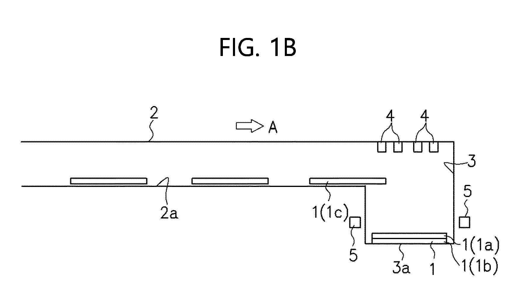
Fig. 1B] Fig. 1B is a view for explaining the manufacturing method and the manufacturing apparatus of the laminated iron core according to the embodiment. - [
Fig. 1C] Fig. 1C is a view for explaining the manufacturing method and the manufacturing apparatus of the laminated iron core according to the embodiment. - [
Fig. 2] Fig. 2 is a view illustrating one example of a rotary electric machine. - Hereinafter, preferred embodiments of the present invention will be explained while referring to the attached drawings.
- A manufacturing method and a manufacturing apparatus of a laminated iron core according to an embodiment will be explained while referring to
Fig. 1A to Fig. 1C . The laminated iron core is an iron core obtained by laminating thin steel sheets whose surfaces are subjected to insulation treatment (referred to as "unit iron cores" in the present application). - A manufacturing apparatus of a laminated iron core according to an embodiment includes a
progressive die 2 that presses an electrical steel sheet to obtain aunit iron core 1, and alamination space 3 in which theunit iron cores 1 after being subjected to a final pressing step in theprogressive die 2 are laminated. - Although illustrated simply in
Fig. 1A to Fig. 1C , theprogressive die 2 is a die in which a plurality of pressing steps can be performed, and pressing is performed in sequence while automatically feeding a material to the next step every one shot, as indicated by an arrow mark A in the drawings. Accordingly, it is possible to punch the electrical steel sheet little by little to form theunit iron core 1 having a complicated shape. Theunit iron core 1 after being subjected to the final pressing step in theprogressive die 2 has a thin disk shape punched into a predetermined shape (for example, a ring shape having predetermined outside diameter and inside diameter) (refer toPatent Literature 1, and so on). - A coating containing an adhesive that exhibits adhesive ability through heating is performed on the electrical steel sheet to be the material of the
unit iron core 1, and thus a coating containing the adhesive is provided to the electrical steel sheet, at the stage where the electrical steel sheet is put in theprogressive die 2. It is only required to design that the coating containing the adhesive is already provided to the electrical steel sheet wound in a state of coil, shipped from a manufacturer, for example. - For the purpose of realizing not only securement of insulation performance but also suppression of rust generation, and the like, an insulating coating is generally provided to a sheet surface of an electrical steel sheet. For example, the coating containing the adhesive may also be this insulating coating in which the adhesive is contained. Further, a coating containing the adhesive may also be provided, separately from the insulating coating. The coating containing the adhesive includes a coating formed only of the adhesive, and it may also be formed by coating the adhesive onto the insulating coating, for example. Note that the coating containing the adhesive may also be formed by partially coating the adhesive onto the insulating coating.
- The coating containing the adhesive is preferably provided to a front surface and a rear surface being two sheet surfaces of the
unit iron core 1. This is because, since there exist the coatings on two sheet surfaces that face each other when theunit iron cores 1 are laminated, theunit iron cores 1 can be adhered to each other more securely. However, it is only required that the coating exists on an entire sheet surface of at least one of the two sheet surfaces that face each other when theunit iron cores 1 are laminated. Therefore, the coating may also be formed only on one sheet surface out of the two sheet surfaces of theunit iron core 1. Note that the coating is preferably formed so as to cover the entire area of the sheet surface of theunit iron core 1, but it may also be formed on an area of 50% or more of the entire area of the sheet surface of theunit iron core 1, and it may also be formed on an area of 70% or more, or 90% or more of the entire area. - The coating changes, when it exhibits the adhesive ability, from a state where an adherend (the
unit iron core 1, in the present embodiment) cannot be adhered to the coating to a state where the adherend can be adhered to the coating. Therefore, the state of the coating changes, through heating, from a state where the coating cannot be adhered to the adherend to a state where the coating can be adhered to the adherend. It is possible to check whether or not the adhesive ability is exhibited, by the following method, for example. - First, from an electrical steel sheet having a configuration same as that of the electrical steel sheet used for the
unit iron core 1, two rectangular electrical steel sheets are cut out. At this time, the coating formed on the entire sheet surface of each of the two electrical steel sheets, is in a state where the adhesive ability is not exhibited (specifically, in a state of not being heated). Further, a size of each of the two electrical steel sheets is 30 mm in width and 60 mm in length. The sheet surfaces of tip portions of such two electrical steel sheets are overlapped to each other. A size of an overlapped region (the sheet surfaces of the tip portions) is 30 mm in width and 10 mm in length. The two electrical steel sheets in which the sheet surfaces of the tip portions are overlapped to each other, are adhered under a condition including a steel sheet temperature of 180°C, a pressure of 10 MPa, and a pressurization time of one hour. Note that the steel sheet temperature (= 180°C) differs depending on a component and the like of the coating. The steel sheet temperature is set to be equal to or more than a temperature that is previously determined as a temperature at which the coating exhibits the adhesive ability. The two electrical steel sheets adhered as above, are used as a test piece. Shearing tensile strength of the test piece is measured under a condition including an atmospheric temperature of 25°C, and a tensile rate of 3 mm/minute. A numeric value obtained by dividing the shearing tensile strength by an adhesion area (= 300 mm2) is calculated as adhesive strength (MPa). When the adhesive strength is 2.5 MPa or more, it can be determined that the adhesive ability is exhibited. - Further, it is also possible that the electrical steel sheet is collected from the laminated iron core, and the collected electrical steel sheet is used to produce a test piece having a configuration same as that of the above-described test piece. In this case, when the adhesive strength of the test piece is 2.5 MPa or more, it can be determined that the adhesive ability is exhibited in the laminated iron core. Note that when the adhesive strength of the test piece is 2.5 MPa or more, this corresponds to the fact that the adhesive strength of the electrical steel sheet in the laminated iron core is 2.5 MPa or more.
- The adhesive contained in the coating is not limited to a specific adhesive. For example, various kinds of adhesive such as an acrylic resin adhesive, a cyanoacrylate-based adhesive, an epoxy resin adhesive, a polyester adhesive, a polyurethane adhesive, a melamine resin adhesive, and a phenol resin adhesive, may also be used. As an example that is further suitable as the adhesive, there can be cited a thermosetting organic resin adhesive whose chemical reaction proceeds through heating. Concretely, an adhesive containing one kind or two kinds or more of resins such as an epoxy resin, a phenol resin, a urethane resin, and a melamine resin, as a main component, may also be used. Further, it is also possible to use a polyester resin and/or an acrylic resin and the like to which a crosslinking agent is added to give a thermosetting property thereto. Further, it is also possible to use an inorganic adhesive in which a dehydration condensation reaction proceeds through heating to cause curing.
- Further, the adhesive contained in the coating may also be an anaerobic adhesive. In this case, the adhesive contained in the coating exhibits the adhesive ability through heating and blocking of air. Therefore, it is designed that when the coating and the adherend are adhered to each other, a space is prevented from being generated between the coating and the adherend. For example, it is also possible that an adhesive layer is formed on the coating such as the insulating coating, and then heating and pressing of the coating and the adhesive layer are performed, to thereby form the coating containing the adhesive.
- The
lamination space 3 is arranged so as to be adjacent to a position of the final pressing step in theprogressive die 2. Thelamination space 3 has abottom surface 3a at a position lower than aconveyance path 2a of theprogressive die 2, for example, and it is configured that theunit iron cores 1 after being subjected to the final pressing step are dropped via a not-illustrated guide, to be laminated one after another. Theunit iron cores 1 subjected to the final pressing step in theprogressive die 2 and then conveyed in sequence to thelamination space 3 are in the same direction, so that theunit iron cores 1 are laminated by being dropped in thelamination space 3 without changing the direction. - At an upper part of the
lamination space 3, a plurality oflaser oscillators 4 are disposed. Therespective laser oscillators 4 irradiate partial regions of theunit iron core 1 of an uppermost layer laminated in the lamination space 3 (aunit iron core 1a inFig. 1A , and aunit iron core 1c inFig. 1C ) with laser beams, to thereby partially heat theunit iron core 1. When using the laser beam, the partial heating means heating of a partial region of a sheet surface of theunit iron core 1. Concretely, it is possible to define that a region physically irradiated with the laser beam on theunit iron core 1 is a partial region of the entire area of the sheet surface of theunit iron core 1. These plurality oflaser oscillators 4 function as a heating unit that heats the sheet surface of theunit iron core 1 at a plurality of partial regions. Two or more of regions out of these plurality of partial regions are set to be at positions separated from each other. Note that the present embodiment exemplifies a case where all of a plurality of partial regions to be heated are at positions separated from each other. However, the plurality of partial regions to be heated may also include two or more of regions that are not separated from each other. - Here, the heating means that the
unit iron core 1 is heated to a temperature equal to or more than a temperature at which the adhesive ability of the coating containing the adhesive formed on the sheet surface of theunit iron core 1 is exhibited. The temperature at which the adhesive ability of the coating containing the adhesive is exhibited is determined by a specification of the coating presented by a manufacturer of the coating or the adhesive, for example. Further, a shape of the region irradiated with the laser beam on the sheet surface of theunit iron core 1, can be set to a point shape, for example. By using the laser heating, it is possible to heat theunit iron core 1 at a pinpoint, and only the coating formed at a portion corresponding to the region to be heated of theunit iron core 1 exhibits the adhesive ability, resulting in that theunit iron cores 1 can be partially adhered to each other at a plurality of regions, in a point manner, respectively. By making theunit iron cores 1 to be partially adhered to each other at the plurality of regions, it is possible to reduce a compressive stress applied to theunit iron cores 1 to improve a core loss property of the laminated iron core. Further, by making theunit iron cores 1 to be partially adhered to each other at the plurality of regions, it is possible to reduce a risk that the adhesion (fixing) of theunit iron cores 1 becomes insufficient. Note that although the example of using thelaser oscillators 4 is adopted, it is also possible to use another heating unit. Another heating unit includes, for example, induction heating (IH), a halogen lamp, blowing of hot air, and the like, and any of the units may be selected. Also in a case of using these heating units, it is possible to partially heat theunit iron core 1 by heating only the partial regions of the sheet surface of theunit iron core 1. - Note that when heating the
unit iron core 1, it is possible to adjust laser beam intensity and the like so that only one laminatedunit iron core 1 of the uppermost layer is heated. In this case, it is also possible to design that out of the laminated plurality ofunit iron cores 1, theunit iron cores 1 except for theunit iron core 1 of the uppermost layer are not heated, so that only theunit iron core 1 of the uppermost layer and oneunit iron core 1 right under the uppermost layer (one layer under the uppermost layer) are adhered to each other and the otherunit iron cores 1 are not adhered to each other. When only theunit iron core 1 of the uppermost layer is heated, a part of the coating formed between theunit iron core 1 of the uppermost layer and theunit iron core 1 right under it is heated, and the adhesive ability is exhibited. Further, theunit iron core 1 of the uppermost layer and theunit iron core 1 right under it are partially adhered. By repeating this every time theunit iron core 1 of the uppermost layer is laminated, it is possible to surely secure the adhesive strength of the laminated iron core with no variation. - From a viewpoint of realizing both the reduction in the compressive stress that is applied to the electrical steel sheets, and the reduction in risk that the adhesion (fixing) of the electrical steel sheets becomes insufficient, the number of regions to be heated at the sheet surface of the unit iron core may be set to 0.3 × Nt or more and 6.0 × Nt or less, it is preferably set to 0.4 × Nt or more and 4.0 × Nt or less, and it is more preferably set to 0.5 × Nt or more and 2.0 × Nt or less, when the number of teeth of a stator core is set to Nt (in a case of a rotor core, the number of teeth of a stator core to be paired with the rotor core is set to Nt), for example. The number of regions to be heated may also be set to, for example, three or more or four or more, and further, it may also be set to six or more or twelve or more. A ratio of a total area of the regions to be heated at one sheet surface of the electrical steel sheet 10 to an area of the one sheet surface is preferably set to 5% or more and 70% or less, and more preferably set to 10% or more and 50% or less, for example. For example, it is also possible to design such that at least one region to be heated exists in each of a plurality of divided regions obtained by dividing a region of one sheet surface of the electrical steel sheet 10 into two or more and twenty or less, or three or more and twenty or less so that each region has the same area. Note that the region to be heated indicates a region of the unit iron core to be heated to a temperature equal to or more than the temperature at which the adhesive ability of the coating containing the adhesive formed on the sheet surface of the unit iron core is exhibited, and is a region irradiated with the laser beam on the sheet surface of the unit iron core, for example. Further, in the region to be heated, the sheet surface of the unit iron core to be heated and the sheet surface of the unit iron core adjacent to the unit iron core to be heated in the lamination direction are adhered to each other. Accordingly, the number and the area of the regions to be heated preferably match the number and the area of the regions at which the sheet surfaces of the unit iron cores adjacent in the lamination direction are adhered to each other.
- Further, at side portions of the
lamination space 3, pressurizingparts 5 that function as a pressurizing unit that pressurizes theunit iron cores 1 laminated in thelamination space 3 are disposed. The pressurizingparts 5 are configured in a vertically movable manner with respect to thelamination space 3 and in a retractable manner from thelamination space 3. The pressurizingparts 5 perform pressurization so as to press against an upper surface of theunit iron core 1 of the uppermost layer (theunit iron core 1a inFig. 1A , and theunit iron core 1c inFig. 1C ) laminated in thelamination space 3. - Hereinafter, a manufacturing method of a laminated iron core according to an embodiment will be explained.
- As illustrated in
Fig. 1A , when, in a state where one unit iron core 1b after being subjected to the final pressing step in theprogressive die 2 is in thelamination space 3, oneunit iron core 1a after being subjected to the final pressing step in theprogressive die 2 is laminated, partial regions of a sheet surface of theunit iron core 1a of the uppermost layer are irradiated with laser beams from thelaser oscillators 4 to partially heat theunit iron core 1a at a plurality of regions, resulting in that partial regions of the coating between theunit iron core 1a and the unit iron core 1b of a lower layer thereof exhibit the adhesive ability, and theunit iron core 1a is adhered, in a point manner, to the unit iron core 1b at the plurality of regions. By using the anaerobic adhesive, the adhesive ability is exhibited between a lower surface of theunit iron core 1a and an upper surface of the unit iron core 1b at which the air is blocked. Note that at a point of time where theunit iron core 1a is laminated and before it is heated, a temperature of theunit iron core 1a does not become a temperature equal to or more than the temperature at which the adhesive ability of the coating is exhibited, and thus the adhesive ability of the coating is not exhibited. - At this time, by performing the pressurization, with the pressurizing
parts 5, so as to press against the upper surface of theunit iron core 1a of the uppermost layer, it is possible to increase the adhesive strength between theunit iron cores 1 by preventing a gap from being generated between theunit iron core 1a and the unit iron core 1b. - Next, as illustrated in
Fig. 1B , the irradiation of laser beams by thelaser oscillators 4 is stopped, and the pressurizingparts 5 are retracted from thelamination space 3, to wait for the lamination of the next oneunit iron core 1c after being subjected to the final pressing step in theprogressive die 2. - After the lamination of the next one
unit iron core 1c, as illustrated inFig. 1C , partial regions of a sheet surface of theunit iron core 1c of the uppermost layer are irradiated with laser beams from thelaser oscillators 4 to partially heat theunit iron core 1c, resulting in that partial regions of the coating between theunit iron core 1c and theunit iron core 1a of a lower layer thereof exhibit the adhesive ability, and theunit iron core 1c is adhered, in a point manner, to theunit iron core 1a at the plurality of regions. By using the anaerobic adhesive, the adhesive ability is exhibited between a lower surface of theunit iron core 1c and the upper surface of theunit iron core 1a at which the air is blocked. Note that at a point of time where theunit iron core 1c is laminated and before it is heated, a temperature of theunit iron core 1c does not become a temperature equal to or more than the temperature at which the adhesive ability of the coating is exhibited, and thus the adhesive ability of the coating is not exhibited. - At this time, by performing the pressurization, with the pressurizing
parts 5, so as to press against the upper surface of theunit iron core 1c of the uppermost layer, it is possible to increase the adhesive strength between theunit iron cores 1 by preventing a gap from being generated between theunit iron core 1c and theunit iron core 1a. - Further, since the heating and pressurization of the
unit iron cores 1 laminated in thelamination space 3 are performed, the lamination, and the heating and pressurization are performed at the same position. - By repeating such steps illustrated in
Fig. 1A to Fig. 1C by the number of requiredunit iron cores 1, it is possible to complete the laminated iron core. - As described above, the pressing of the electrical steel sheet using the
progressive die 2 to obtain theunit iron core 1, and the lamination of thisunit iron core 1, can be performed substantially simultaneously as a series of operation. Further, since it is designed that the heating is performed in thelamination space 3 after the lamination, the lamination position and the heating position can be set to the same position, and thus there is no need to move theunit iron core 1 between the positions. Besides, the heating is designed to be performed after the lamination, so that there is no chance that theunit iron core 1 is heated in the die and adhered to the die. - As described above, by performing the presswork and the lamination substantially simultaneously as a series of operation, it is possible to increase the efficiency of manufacture of the laminated iron core without increasing the man-hour.
- Note that when the lamination position and the heating position are the same position, this means not only a case where they are strictly the same position but also a case where the lamination position and the heating position are substantially the same position. When the lamination position and the heating position are substantially the same position, this means that, for example, in the
lamination space 3, the laminatedunit iron core 1 is heated while its position is displaced from the lamination position by a distance of 1/2 or less a width of theunit iron core 1. - Note that in the present embodiment, the heating of the
unit iron core 1 of the uppermost layer is repeated every time oneunit iron core 1 is laminated, but it is also possible to repeat the heating of theunit iron core 1 of the uppermost layer every time a predetermined plurality ofunit iron cores 1 are laminated. If the number ofunit iron cores 1 required for completing the laminated iron core is set to N, the number of the predetermined plurality of unit iron cores is preferably set to half or less the number (N/2 or less). Further, the laser beam intensity is set so that when the unit iron core of the uppermost layer is heated, one or more of unit iron cores of a lower layer thereof can be simultaneously heated to a temperature equal to or more than the temperature at which the coating exhibits the adhesive ability. By simultaneously heating the plurality of unit iron cores including the unit iron core of the uppermost layer, the coatings formed on the sheet surfaces of the plurality of unit iron cores respectively exhibit the adhesive ability, and the plurality of unit iron cores can be collectively adhered to each other. Accordingly, it is possible to efficiently manufacture the laminated iron core. However, when theunit iron core 1 of the uppermost layer is heated every time a plurality of, for example, twounit iron cores 1 are laminated, there is a need to make the twounit iron cores 1 laminated this time to be adhered to each other, and to make the aboveunit iron cores 1 to be adhered to theunit iron core 1 that has already existed in thelamination space 3 before the lamination this time. For this reason, there is a need to increase the laser beam intensity, and further, there is a possibility that the temperature becomes difficult to be increased toward the lower layer, and a variation in adhesive strength occurs between layers. With respect to this, when theunit iron core 1 of the uppermost layer is heated every time oneunit iron core 1 is laminated, as in the present embodiment, it is possible to prevent the occurrence of variation in the adhesive strength between layers. - Further, as illustrated in
Fig. 1A and Fig. 1C , it is designed that the pressurization is performed by the pressurizingparts 5 during the irradiation of laser beams. By performing the pressurization during the irradiation of laser beams as above, it is possible to increase the adhesion accuracy. However, it is not limited to this, and it is also possible to perform the pressurization at a timing before or after the irradiation of laser beams, for example. - Further, it is also possible to adopt a configuration in which the height of the
bottom surface 3a of thelamination space 3 is variable. In this case, by lowering thebottom surface 3a in accordance with the increase in the number ofunit iron cores 1 to be laminated, the height position of theunit iron core 1 of the uppermost layer can be kept substantially constant. This eliminates the necessity of vertically moving the pressurizingparts 5 in accordance with the height of theunit iron core 1 of the uppermost layer. Further, a distance between thelaser oscillators 4 and theunit iron core 1 of the uppermost layer can be kept constant, and if the laser beam intensity is set to be constant, it is possible to achieve a constant heating effect.
a view illustrating one example of a configuration of equipment having the laminated iron core manufactured by using the manufacturing method of the laminated iron core of the present embodiment.Fig. 2 exemplifies a case where the equipment is a rotary electric machine. Further,Fig. 2 illustrates a cross section of the rotary electric machine when the rotary electric machine is cut perpendicular to itscenter line 0. An x-y plane direction is a sheet surface direction of the unit iron core. - In
Fig. 2 , the rotary electric machine has astator 510 and a rotor 520. Thestator 510 has astator core 511 and astator coil 512. The rotor 520 has arotor core 521 andpermanent magnets 522a to 5221. - Both the
stator core 511 and therotor core 521 may also be the laminated iron cores manufactured by using the manufacturing method of the laminated iron core of the present embodiment, and only either of them may also be the laminated iron core manufactured by using the manufacturing method of the laminated iron core of the present embodiment. -
Fig. 2 exemplifies a case where thestator core 511 has sixteeth 511a to 511f. Note that as long as at least one of the stator core and the rotor core is manufactured by using the manufacturing method of the laminated iron core of the present embodiment, a configuration of an IPM motor is not limited to the configuration exemplified inFig. 2 . For example, a flux barrier may also be formed in the rotor core. - Further,
Fig. 2 exemplifies a case where the rotary electric machine is the IPM (Interior Permanent Magnet) motor. However, the rotary electric machine is not limited to the IPM motor. For example, the rotary electric machine may also be a motor other than the IPM motor. Further, the rotary electric machine may also be a power generator. - Although the present invention has been explained together with the embodiments, the above-described embodiments merely illustrate concrete examples of implementing the present invention, and the technical scope of the present invention is not to be construed in a restrictive manner by these embodiments. That is, the present invention may be implemented in various forms without departing from the technical spirit or main features thereof.
Claims (9)
- A manufacturing method of a laminated iron core, comprising:a step of pressing, with a die, an electrical steel sheet having a coating containing an adhesive that exhibits adhesive ability through heating, provided to a sheet surface thereof, to obtain a unit iron core; anda step of laminating the unit iron cores pressed with the die, and heating the sheet surface of the unit iron core of an uppermost layer at a plurality of partial regions to make the unit iron core of the uppermost layer to be partially adhered to the unit iron core of a lower layer thereof at a plurality of regions.
- The manufacturing method of the laminated iron core according to claim 1, further comprising
a step of pressurizing the laminated unit iron cores. - The manufacturing method of the laminated iron core according to claim 1 or 2, wherein:the die is a progressive die; andthe unit iron cores after being subjected to a final pressing step in the progressive die are laminated.
- The manufacturing method of the laminated iron core according to any one of claims 1 to 3, wherein
at a lamination position of laminating the unit iron cores, the laminated unit iron core of the uppermost layer is heated. - The manufacturing method of the laminated iron core according to any one of claims 1 to 4, wherein
the unit iron core of the uppermost layer is heated every time one of the unit iron cores is laminated. - A manufacturing apparatus of a laminated iron core, comprising:a progressive die that presses an electrical steel sheet having a coating containing an adhesive that exhibits adhesive ability through heating, provided to a sheet surface thereof, to obtain a unit iron core;a lamination space in which the unit iron cores after being subjected to a final pressing step in the progressive die are laminated; anda heating unit that is disposed at an upper part of the lamination space and that heats the sheet surface of the unit iron core of an uppermost layer laminated in the lamination space, at a plurality of partial regions.
- The manufacturing apparatus of the laminated iron core according to claim 6, further comprisinga pressurizing unit that pressurizes the unit iron cores laminated in the lamination space, whereinthe pressurizing unit is configured in a retractable manner from the lamination space.
- A laminated iron core manufactured through a step of pressing, with a die, an electrical steel sheet having a coating containing an adhesive that exhibits adhesive ability through heating, provided to a sheet surface thereof, to obtain a unit iron core, and a step of laminating the unit iron cores pressed with the die, and heating the sheet surface of the unit iron core of an uppermost layer at a plurality of partial regions to make the unit iron core of the uppermost layer to be partially adhered to the unit iron core of a lower layer thereof at a plurality of regions.
- A rotary electric machine, comprising the laminated iron core according to claim 8.
Applications Claiming Priority (2)
| Application Number | Priority Date | Filing Date | Title |
|---|---|---|---|
| JP2022142853 | 2022-09-08 | ||
| PCT/JP2023/029881 WO2024053364A1 (en) | 2022-09-08 | 2023-08-18 | Laminated iron core manufacturing method, manufacturing device, laminated iron core, and roating electric machine |
Publications (2)
| Publication Number | Publication Date |
|---|---|
| EP4546624A1 true EP4546624A1 (en) | 2025-04-30 |
| EP4546624A4 EP4546624A4 (en) | 2025-11-26 |
Family
ID=90190969
Family Applications (1)
| Application Number | Title | Priority Date | Filing Date |
|---|---|---|---|
| EP23862904.2A Pending EP4546624A4 (en) | 2022-09-08 | 2023-08-18 | METHOD FOR PRODUCE A LAMINATED IRON CORE, MANUFACTURING DEVICE, LAMINATED IRON CORE AND ROTATING ELECTRIC MACHINE |
Country Status (9)
| Country | Link |
|---|---|
| US (1) | US20250167644A1 (en) |
| EP (1) | EP4546624A4 (en) |
| JP (1) | JP7513941B1 (en) |
| KR (1) | KR102922407B1 (en) |
| CN (1) | CN119731916A (en) |
| CA (1) | CA3261223A1 (en) |
| MX (1) | MX2025002083A (en) |
| TW (1) | TWI891048B (en) |
| WO (1) | WO2024053364A1 (en) |
Family Cites Families (14)
| Publication number | Priority date | Publication date | Assignee | Title |
|---|---|---|---|---|
| JP3745490B2 (en) | 1997-03-19 | 2006-02-15 | 新日本製鐵株式会社 | Core manufacturing method and electrical steel sheet suitable for the method |
| JP2002151335A (en) | 2000-11-10 | 2002-05-24 | Nippon Steel Corp | Laminated iron core excellent in iron loss characteristics and method of manufacturing the same |
| JP2005210817A (en) * | 2004-01-22 | 2005-08-04 | Matsushita Electric Ind Co Ltd | Magnetic laminated iron core and manufacturing method thereof |
| DE102012001744B4 (en) * | 2012-01-28 | 2026-07-02 | Volkswagen Aktiengesellschaft | Method and apparatus for the simultaneous production of several different sheet metal stacks from several stacked electrical steel sheets |
| JP6466962B2 (en) | 2014-11-20 | 2019-02-06 | 黒田精工株式会社 | Laminated core manufacturing apparatus, laminated core manufacturing method, and laminated core |
| DE102016225853A1 (en) * | 2016-12-21 | 2018-06-21 | Volkswagen Aktiengesellschaft | Method and device for producing a laminated core |
| JP7515403B2 (en) * | 2018-12-17 | 2024-07-12 | 日本製鉄株式会社 | Adhesive laminated core for stator, manufacturing method thereof, and rotating electric machine |
| DE102019113291A1 (en) | 2019-05-20 | 2020-11-26 | Thyssenkrupp Steel Europe Ag | Sheet metal for the production of an electromagnetic component, in particular a stator assembly or a rotor assembly, and a method for manufacturing an electromagnetic component |
| DE102020109985A1 (en) * | 2020-04-09 | 2021-10-14 | Thyssenkrupp Steel Europe Ag | Method for producing a laminated core, laminated core and electrical machine |
| JP7833862B2 (en) * | 2020-06-17 | 2026-03-23 | 日本製鉄株式会社 | Stacked core and method for manufacturing a stacked core |
| JP7636669B2 (en) * | 2020-06-17 | 2025-02-27 | 日本製鉄株式会社 | Manufacturing method of laminated core |
| MX428685B (en) * | 2020-06-17 | 2025-11-13 | Nippon Steel Corp | Layered core manufacturing method |
| MX428275B (en) * | 2020-07-07 | 2025-11-13 | Nippon Steel Corp | Method for manufacturing adhered laminate core and adhered laminate core manufacturing device |
| JP7782135B2 (en) | 2021-03-17 | 2025-12-09 | 東レ株式会社 | molded product |
-
2023
- 2023-08-18 CA CA3261223A patent/CA3261223A1/en active Pending
- 2023-08-18 CN CN202380059119.3A patent/CN119731916A/en active Pending
- 2023-08-18 US US18/880,212 patent/US20250167644A1/en active Pending
- 2023-08-18 EP EP23862904.2A patent/EP4546624A4/en active Pending
- 2023-08-18 WO PCT/JP2023/029881 patent/WO2024053364A1/en not_active Ceased
- 2023-08-18 KR KR1020257003883A patent/KR102922407B1/en active Active
- 2023-08-18 JP JP2023567142A patent/JP7513941B1/en active Active
- 2023-08-22 TW TW112131496A patent/TWI891048B/en active
-
2025
- 2025-02-20 MX MX2025002083A patent/MX2025002083A/en unknown
Also Published As
| Publication number | Publication date |
|---|---|
| TW202416629A (en) | 2024-04-16 |
| EP4546624A4 (en) | 2025-11-26 |
| CA3261223A1 (en) | 2025-04-29 |
| KR102922407B1 (en) | 2026-02-05 |
| TWI891048B (en) | 2025-07-21 |
| MX2025002083A (en) | 2025-04-02 |
| CN119731916A (en) | 2025-03-28 |
| WO2024053364A1 (en) | 2024-03-14 |
| KR20250026363A (en) | 2025-02-25 |
| JP7513941B1 (en) | 2024-07-10 |
| US20250167644A1 (en) | 2025-05-22 |
| JPWO2024053364A1 (en) | 2024-03-14 |
Similar Documents
| Publication | Publication Date | Title |
|---|---|---|
| CA2971381C (en) | Punch processing method for laminated iron core and method for manufacturing laminated iron core | |
| EP2083502A2 (en) | Laminated core, method and apparatus for manufacturing laminated core, and stator | |
| US9330840B2 (en) | Apparatus for manufacturing field pole magnetic body | |
| KR102664817B1 (en) | Manufacturing method of laminated core | |
| JP4345480B2 (en) | Manufacturing apparatus and manufacturing method of laminated iron core | |
| JP7833862B2 (en) | Stacked core and method for manufacturing a stacked core | |
| US20250167644A1 (en) | Manufacturing method of laminated iron core, manufacturing apparatus of laminated iron core, laminated iron core, and rotary electric machine | |
| JP2004023829A (en) | Manufacturing method of laminate | |
| EP3363028B1 (en) | Tank comprising a magnetic shunt assembly for magnetic shielding of a power device | |
| EP4718692A1 (en) | Method and apparatus for producing divided core | |
| RU2854819C2 (en) | Method for manufacturing layered iron core, layerediron core and rotating electric machine | |
| JP2019187056A (en) | Core of rotary electric machine, and method of manufacturing core of rotary electric mashine | |
| KR102727029B1 (en) | Apparatus for manufacturing laminated core of motor | |
| US20230208258A1 (en) | Permanent magnet recovery device and permanent magnet recovery method | |
| JP6487003B2 (en) | Manufacturing method of laminated iron core | |
| JP7584888B2 (en) | Manufacturing method and manufacturing device for laminated core | |
| KR102597719B1 (en) | Laminated core having improved quality uniformity and electromagnetic performance, and manufacturing method thereof | |
| JP7862760B2 (en) | Method for manufacturing a laminated core and apparatus for manufacturing a laminated core | |
| JP7680704B2 (en) | Laminated core, and manufacturing device and method thereof | |
| TWI891046B (en) | Method for manufacturing laminated iron core, device for manufacturing laminated iron core, laminated iron core, and rotating motor | |
| JP4776095B2 (en) | Iron core manufacturing method and apparatus | |
| RU2812241C1 (en) | Method for manufacturing layered core | |
| US20260081506A1 (en) | Method and system for producing a stator for an electric machine | |
| EP4712120A1 (en) | Apparatus and method for manufacturing laminated core | |
| JP2024022823A (en) | Magnet manufacturing method |
Legal Events
| Date | Code | Title | Description |
|---|---|---|---|
| STAA | Information on the status of an ep patent application or granted ep patent |
Free format text: STATUS: THE INTERNATIONAL PUBLICATION HAS BEEN MADE |
|
| PUAI | Public reference made under article 153(3) epc to a published international application that has entered the european phase |
Free format text: ORIGINAL CODE: 0009012 |
|
| STAA | Information on the status of an ep patent application or granted ep patent |
Free format text: STATUS: REQUEST FOR EXAMINATION WAS MADE |
|
| 17P | Request for examination filed |
Effective date: 20250123 |
|
| AK | Designated contracting states |
Kind code of ref document: A1 Designated state(s): AL AT BE BG CH CY CZ DE DK EE ES FI FR GB GR HR HU IE IS IT LI LT LU LV MC ME MK MT NL NO PL PT RO RS SE SI SK SM TR |
|
| A4 | Supplementary search report drawn up and despatched |
Effective date: 20251027 |
|
| RIC1 | Information provided on ipc code assigned before grant |
Ipc: H02K 15/02 20250101AFI20251021BHEP Ipc: H01F 41/02 20060101ALI20251021BHEP Ipc: B32B 37/12 20060101ALI20251021BHEP Ipc: H02K 15/021 20250101ALI20251021BHEP Ipc: B21D 28/02 20060101ALI20251021BHEP Ipc: H01F 3/02 20060101ALI20251021BHEP |
|
| DAV | Request for validation of the european patent (deleted) | ||
| DAX | Request for extension of the european patent (deleted) | ||
| GRAP | Despatch of communication of intention to grant a patent |
Free format text: ORIGINAL CODE: EPIDOSNIGR1 |
|
| STAA | Information on the status of an ep patent application or granted ep patent |
Free format text: STATUS: GRANT OF PATENT IS INTENDED |
|
| INTG | Intention to grant announced |
Effective date: 20260618 |