EP4546391A2 - Schutzvorrichtung für eine elektrische wechselstromanlage - Google Patents
Schutzvorrichtung für eine elektrische wechselstromanlage Download PDFInfo
- Publication number
- EP4546391A2 EP4546391A2 EP25163085.1A EP25163085A EP4546391A2 EP 4546391 A2 EP4546391 A2 EP 4546391A2 EP 25163085 A EP25163085 A EP 25163085A EP 4546391 A2 EP4546391 A2 EP 4546391A2
- Authority
- EP
- European Patent Office
- Prior art keywords
- trigger
- coil
- relay coil
- circuit
- magnetic
- Prior art date
- Legal status (The legal status is an assumption and is not a legal conclusion. Google has not performed a legal analysis and makes no representation as to the accuracy of the status listed.)
- Pending
Links
Images


Classifications
-
- H—ELECTRICITY
- H01—ELECTRIC ELEMENTS
- H01H—ELECTRIC SWITCHES; RELAYS; SELECTORS; EMERGENCY PROTECTIVE DEVICES
- H01H71/00—Details of the protective switches or relays covered by groups H01H73/00 - H01H83/00
- H01H71/04—Means for indicating condition of the switching device
-
- H—ELECTRICITY
- H01—ELECTRIC ELEMENTS
- H01H—ELECTRIC SWITCHES; RELAYS; SELECTORS; EMERGENCY PROTECTIVE DEVICES
- H01H71/00—Details of the protective switches or relays covered by groups H01H73/00 - H01H83/00
- H01H71/10—Operating or release mechanisms
- H01H71/12—Automatic release mechanisms with or without manual release
- H01H71/123—Automatic release mechanisms with or without manual release using a solid-state trip unit
- H01H71/125—Automatic release mechanisms with or without manual release using a solid-state trip unit characterised by sensing elements, e.g. current transformers
-
- H—ELECTRICITY
- H01—ELECTRIC ELEMENTS
- H01H—ELECTRIC SWITCHES; RELAYS; SELECTORS; EMERGENCY PROTECTIVE DEVICES
- H01H71/00—Details of the protective switches or relays covered by groups H01H73/00 - H01H83/00
- H01H71/10—Operating or release mechanisms
- H01H71/12—Automatic release mechanisms with or without manual release
- H01H71/24—Electromagnetic mechanisms
- H01H71/2463—Electromagnetic mechanisms with plunger type armatures
-
- H—ELECTRICITY
- H01—ELECTRIC ELEMENTS
- H01H—ELECTRIC SWITCHES; RELAYS; SELECTORS; EMERGENCY PROTECTIVE DEVICES
- H01H71/00—Details of the protective switches or relays covered by groups H01H73/00 - H01H83/00
- H01H71/10—Operating or release mechanisms
- H01H71/12—Automatic release mechanisms with or without manual release
- H01H71/24—Electromagnetic mechanisms
- H01H71/2481—Electromagnetic mechanisms characterised by the coil design
-
- H—ELECTRICITY
- H01—ELECTRIC ELEMENTS
- H01H—ELECTRIC SWITCHES; RELAYS; SELECTORS; EMERGENCY PROTECTIVE DEVICES
- H01H71/00—Details of the protective switches or relays covered by groups H01H73/00 - H01H83/00
- H01H71/74—Means for adjusting the conditions under which the device will function to provide protection
-
- H—ELECTRICITY
- H01—ELECTRIC ELEMENTS
- H01H—ELECTRIC SWITCHES; RELAYS; SELECTORS; EMERGENCY PROTECTIVE DEVICES
- H01H73/00—Protective overload circuit-breaking switches in which excess current opens the contacts by automatic release of mechanical energy stored by previous operation of a hand reset mechanism
- H01H73/60—Protective overload circuit-breaking switches in which excess current opens the contacts by automatic release of mechanical energy stored by previous operation of a hand reset mechanism cartridge type, e.g. screw-in cartridge
- H01H73/64—Protective overload circuit-breaking switches in which excess current opens the contacts by automatic release of mechanical energy stored by previous operation of a hand reset mechanism cartridge type, e.g. screw-in cartridge having only electromagnetic release
Definitions
- the invention relates to devices for protecting an alternating current electrical installation.
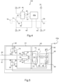
- the electrical appliance 10 shown on the Figure 1 has a generally parallelepiped shape.
- main faces respectively a left face 11 and a right face 12, and lateral faces extending from one to the other of the main faces 11 and 12, namely a rear face 13, an upper face 14, a front face 15 and a lower face 16.
- the rear face 13 has a notch 17 for mounting the device 10 on a standardized support rail with an ⁇ profile (not shown).
- the front face 15 has, in a central position, over approximately half of its length, a nose 18 having a lever 19.
- the device 10 is of the modular type, that is to say that in addition to its generally parallelepiped shape, its width (distance between the two main faces 11 and 12) is a multiple of a standardized value, known as the “module”, which is of the order of 18 mm.
- the device 10 has a width of one module.
- the apparatus 10 is configured, in accordance with the modular format, to belong to a row of modular apparatuses arranged side by side by being fixed from the rear on the horizontally arranged support rail.
- the upper face 14 has two insertion holes 20 and 21 giving access respectively to a connection terminal 22 and to a connection terminal 23.
- the hole 20 and the terminal 22 are located on the left.
- the hole 21 and the terminal 23 are located on the right.
- the lower face 16 has two insertion holes, a first hole and a second hole giving access respectively to a connection terminal 26 and to a connection terminal 27.
- the first hole and the terminal 26 are located on the left.
- the second hole and the terminal 27 are located on the right.
- connection terminals 22, 23, 26 and 27 is designed to receive a stripped end section of an electric cable or a tooth of a horizontal electricity distribution comb whose pitch (center distance between two successive teeth) is one module.
- terminals 22 and 23 located at the top are intended to be connected to the two poles of an electricity distribution network while the two terminals 26 and 27 located at the bottom are intended to be connected to an electrical installation circuit to be protected.
- the device 10 is a single-pole protected differential circuit breaker, i.e. having an electrical circuit operating a short-circuit and overcurrent detection in the path circuit of the protected pole (circuit breaker function) and operating a detection of the difference in intensity of the current flowing in the path circuit of the protected pole and in the path circuit of the unprotected pole (differential function).
- terminal 22 and terminal 26 on the left are intended for the pole of the electrical installation to be protected, which is a phase, while terminal 23 and terminal 27 on the right are intended for the pole of the unprotected electrical installation, which is the neutral.
- the current path circuit between terminals 22 and 26 located on the left comprises in series a magnetic trigger member 30, a fixed contact 31, a movable contact 32, a thermal trigger member 33 and a winding 34 forming part of a differential fault detection transformer 35.
- the routing circuit between terminals 23 and 27 located on the right comprises in series a fixed contact 36, a movable contact 37 and a winding 38 forming part of the differential fault detection transformer 35.
- the transformer 35 comprises, in addition to the winding 34 of the tracking circuit between the terminals 22 and 26 located on the left and the winding 38 of the tracking circuit between the terminals 23 and 27 located on the right, which form the primary windings, a secondary winding 39, and an annular armature (magnetic circuit) 40 around which the secondary winding 39 and the primary windings 34 and 38 are made.
- the secondary winding 39 of the transformer 35 is connected by two electrical conductors 41 and 42 to an electronic card 43.
- the magnetic triggering member 30 is part of a compact member 44 further comprising a triggering relay 45.
- the electronic card 43 is connected on the one hand by two conductors 28 and 29 respectively to terminal 22 and to terminal 23 and on the other hand by two conductors 46 and 47 to the triggering relay 45.
- the device 10 comprises a mechanism 50, generally called a lock.
- the lever 19 located outside the device 10 allows manual action on the lock 50.
- the magnetic triggering member 30, the thermal triggering member 33 and the assembly formed by the triggering relay 45 connected to the electronic card 43 are configured to act if necessary on the lock 50.
- the lock 50 has two stable positions, respectively a disconnected position where the two movable contacts 32 and 37 are each away from the corresponding fixed contacts 31 and 36 and an engaged position where each of the two movable contacts 32 and 37 is supported on the corresponding fixed contacts 31 and 36.
- the lever 19, projecting from the front face 15, allows manual action on the lock 50 to move from the disconnected position to the engaged position or vice versa.
- the magnetic trip member 30, the thermal trip member 33 and the trip relay 45 are configured to automatically act on the lock 50 to move from the latching position to the disconnecting position when predetermined current path conditions occur.
- the magnetic triggering member 30 acts on the lock 50 in the event of a short circuit
- the thermal triggering member 33 acts in the event of a prolonged overcurrent
- the triggering relay 45 acts in the event of a differential fault.
- the magnetic triggering member 30 is formed by a coil arranged around a core controlling a striker acting in the event of a short circuit on the lock 50.
- the thermal triggering member 33 is formed by a bimetallic strip deforming in the event of prolonged overcurrent and acting due to its deformation on the lock 50.
- the triggering relay 45 which is part of the same compact member 44 as the magnetic triggering member 30, is formed by another coil arranged around the same mobile core. This other coil is powered by the electronic card 43 which reacts to the voltage supplied by the secondary winding 39 of the transformer 35 in the event of a difference between the current flowing in the winding 34 and the current flowing in the winding 38, that is to say in the event of a differential fault.
- the trigger relay 45 When the trigger relay 45 is thus energized, it drives the movable core which controls the striker acting on the lock 50 to trigger the transition from the engaged position to the disconnected position.
- the embodiment of the apparatus 10 illustrated in the Figure 3 is similar to the one illustrated on the Figure 2 except that it does not include the thermal tripping device 33, the protection against prolonged overcurrents involving a current measuring transformer 202.
- the transformer 202 comprises an annular armature 203 surrounding a conductive element of the current path circuit between the terminals 22 and 26 and comprises a winding 204 around the annular armature 203.
- the winding 204 is connected to the electronic card 43 by two electrical conductors 205 and 206.
- the card 43 reacts not only to the voltage supplied by the winding 39 of the transformer 35, but also to the voltage supplied by the winding 204 of the current measuring transformer 202.
- the transformer 202 is arranged between the movable contact 32 and the terminal 26, but whereas the thermal trip member 33 is arranged between the movable contact 32 and the winding 34, the transformer 202 is arranged between the winding 34 and the terminal 26.
- the electronic card 43 reacts not only to the voltage supplied by the secondary winding 39 of the transformer 35, but also to the voltage supplied by the winding 204 of the transformer 202.
- the electronic card 43 supplies the trigger relay 45, which drives the movable core which controls the striker acting on the lock 50 to trigger the transition from the engaged position to the disconnected position.
- the invention aims to provide in a simple, convenient and economical manner information on the current flowing in an electrical protection device of an alternating current electrical installation, or information which can be deduced therefrom such as the consumption of electrical energy by the portion of the electrical installation connected to the output terminals of the protection device.
- the communication device allows the protection device to provide the values of the intensity of the current flowing through it, simply with an already existing component, namely the compact device, and an appropriate electronic circuit, which is particularly simple, convenient and economical.
- the invention is based on the observation that the trigger relay coil can be used other than to drive the striker, namely to pick up the current flowing in the magnetic trigger coil and thus in the first tracking circuit.
- the signal provided by the trigger relay coil is representative of the current flowing in the magnetic trigger coil because the magnetic trigger coil and the trigger relay coil are arranged around each other, and consequently interact like the windings of a transformer, even in the absence of a specific coupling element such as a magnetic armature, the coupling between the two coils can be carried out only by the surrounding air.
- the device 100 for protecting an alternating current electrical installation is similar to the device 10 described in support of the figures 1 And 2 except that it does not include a thermal tripping device 33 and does not include a differential fault detection transformer 35, that the electronic card 43 is replaced by an electronic circuit 43a and that the electronic circuit 43a is connected to the first current path circuit between the movable contact 32 and the connection terminal 26 by conductor 48 and connected to the second current path circuit between the movable contact 37 and the connection terminal 27 by conductor 49.
- the apparatus 100 comprises a first incoming connection terminal 22 for a first electrical pole, a second incoming connection terminal 23 for a second electrical pole different from the first electrical pole, a first outgoing connection terminal 26 for the first electrical pole and a second outgoing connection terminal 27 for the second electrical pole.
- connection terminals 22, 23, 26, 27 is configured to receive a stripped end section of an electric cable or a tooth of a horizontal distribution comb.
- the device 100 comprises a first current path circuit between the first incoming connection terminal 22 and the first outgoing connection terminal 26.
- This first current path circuit comprises a fixed contact 31 and a movable contact 32.
- the device 100 further comprises a second current path circuit between the second incoming connection terminal 23 and the second outgoing connection terminal 27.
- This second current path circuit comprises a fixed contact 36 and a movable contact 37.
- a control mechanism 50 of the movable contact 32 and the movable contact 37 has two stable positions, respectively a disconnecting position and an engaging position.
- the movable contact 32 In the disconnected position, the movable contact 32 is away from the fixed contact 31 and the movable contact 37 is away from the fixed contact 36.
- the movable contact 32 rests on the fixed contact 31 and the movable contact 37 rests on the fixed contact 36.
- the apparatus 100 comprises a lever 19 configured to manually act on the control mechanism 50 in order to move from the position from disconnection to the engaged position or from the engaged position to the disconnection position.
- the protection apparatus 100 comprises a compact member 44.
- the compact member 44 comprises a magnetic trigger member 30 and a trigger relay 45.
- the compact member 44 is configured to act on the lock 50 in order to move from the engaged position to the disconnected position when a short circuit or prolonged overcurrent occurs.
- the magnetic trigger member 30 is formed by a magnetic trigger coil 51 arranged around a movable core 103 controlling a striker 102 acting in the event of a short circuit on the control mechanism 50.
- the magnetic trigger coil 51 forms a portion of the first current path circuit.
- the magnetic trigger coil 51 is located between the incoming connection terminal 22 and the fixed contact 31.
- the trigger relay 45 is formed by a trigger relay coil 52 arranged around the movable core 103.
- the trigger relay coil 52 is provided with a first end 110 and a second end 110a.
- the magnetic trigger coil 51 and the trigger relay coil 52 are arranged around each other.
- the magnetic trigger coil 51 is arranged around the trigger relay coil 52.
- the transformation ratio is the ratio between the number of turns of the two windings.
- the electronic circuit 43a of the device 100 is connected to the trigger relay coil 52 by a conductor 46 and by a conductor 47.
- conductor 46 is connected to end 110 and conductor 47 is connected to end 110a.
- the electronic circuit 43a is configured to energize the trip relay coil 52 when predetermined current path conditions representative of a prolonged overcurrent occur.
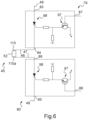
- the electronic circuit 43a comprises a prolonged overcurrent detector 60 and a switching circuit 61.
- the sustained overcurrent detector 60 is configured to determine the presence of current path conditions representative of a sustained overcurrent from the signal present at the ends 110 and 110a of the trip relay coil 52.
- the sustained overcurrent detector 60 is further configured to produce a detection signal when the predetermined current path conditions are present, i.e., in the event of a sustained overcurrent, and then after a predetermined time from the production of the detection signal, to also produce an actuation signal.
- the extended overcurrent detector 60 and the switching circuit 61 are configured so that in the absence of the detection signal the switching circuit 61 connects the trip relay coil 52 to the extended overcurrent detector 60 while isolating the trip relay coil 52 from each of the incoming connection terminals 22, 23.
- the switching circuit 61 isolates the trip relay coil 52 from the prolonged overcurrent detector 60 and then, when the actuating signal becomes present, connects the trip relay coil 52 to each of the incoming connection terminals 22 and 23.
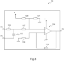
- the prolonged overcurrent detector 60 is implemented by a microcontroller 95 and by an interface 70.
- the interface 70 is arranged between the switching circuit 61 and an analog input port 67 of the microcontroller 95.
- the switching circuit 61 connects the interface 70 to both ends 110 and 110a of the trigger relay coil 52 in the absence of the detection signal and isolates the interface 70 from both ends 110 and 110a of the trigger relay coil 52 in the presence of the detection signal.
- the interface 70 comprises two input connection points 74 and 75 which the switching circuit 61 connects or not respectively to the end 110 and to the end 110a of the coil 52 and an output connection point 76 connected to the analog input port 67 of the microcontroller 95.
- the input connection point 75 is connected to the reference pole of the direct current part of the electronic circuit 43a.
- the switching circuit 61 connects the input connection point 75 to the end 110a of the coil 52, this end is brought to this reference pole.
- the interface 70 is configured to provide the analog input port 67 with an analog signal usable by the microcontroller 95 and corresponding to the voltage present between the two ends 110 and 110a of the trigger relay coil 52.
- the interface 70 comprises an amplifier 114 whose output is connected to the output connection point 76. Between the input connection point 74 and the + input of the amplifier 114 two resistors 116 and 117 are arranged in series. Between the reference pole (to which the input connection point 75 is brought) and the - input of the amplifier 114 is arranged a resistor 118. A capacitor 115 is arranged between the input connection point 75 and the sides of the resistors 116 and 117 connected to each other. A resistor 119 is arranged between the output of the amplifier 114 and its - input. Resistors 120 and 121 are connected to each other. The + input of the amplifier 114 is connected to the side of the resistors 120 and 121 connected to each other. The other sides of the resistors 120 and 121 are connected respectively to the + pole and the reference pole of the power supply of the electronic circuit 43a.
- Resistor 116 and capacitor 115 enable the current flowing in coil 52 to be transformed into voltage and low-pass filtering to be carried out.
- Resistors 117, 120 and 121 allow the polarization of amplifier 114.
- Resistors 118 and 119 are used to set the gain of amplifier 114.
- the prolonged overcurrent detector 60 comprises in the microcontroller 95 a converter 71, a calculation unit 72 and a monitoring unit 73.
- the converter 71 is connected to the analog port 67 of the microcontroller 95 and is configured to produce digital values representative of the analog signal provided by the interface 70.
- the calculation unit 72 is configured to produce, from the digital values representative of the analog signal provided by the interface 70, digital values representative of the effective value of the intensity of the current flowing in the magnetic trigger coil 51.
- the calculation unit 72 is implemented by the conventional technique of calculating the effective value of a sinusoidal signal and by calibration.
- the monitoring unit 73 of the effective value of the current flowing in the magnetic trigger coil 51 is configured to compare the digital values representative of the effective value I of the current intensity with a current intensity threshold “ threshold l ” and if this threshold is exceeded for a predetermined duration “ threshold t ” to produce the detection signal.
- the 73 monitoring unit here complies with the French standard NF C15-100, which is largely harmonized with the European standard HD 384, which describes the tripping time of circuit breakers but which incorporate bimetallic strip technology.
- the monitoring unit 73 When the numerical values representative of the effective value I of the current intensity are less than or equal to 1.13 times the current intensity threshold for less than one hour, the monitoring unit 73 must not produce the detection signal.
- the monitoring unit 73 When the numerical values representative of the effective value I of the current intensity are greater than or equal to 1.45 times the current intensity threshold, the monitoring unit 73 must produce a detection signal in less than one hour.
- the monitoring unit 73 meets a single criterion, for example, when the numerical values representative of the effective value I of the current intensity are equal to 1.2 times the intensity threshold, the monitoring unit 73 produces a detection signal in a few milliseconds, allowing the device to be triggered.
- the detection signal produced by the monitoring unit 73 is available on a port 68 of the microcontroller 95.
- the monitoring unit 73 After a predetermined time after the start of production of the detection signal, the monitoring unit 73 also produces an actuation signal, available on port 69 of the microcontroller 95.
- This predetermined duration depends on the components used and their reaction time, it is between 1ms and 10ms.
- the microcontroller 95 also has a port 66 on which the digital values produced by the calculation unit 72 are available.
- the port 66 is connected to a communication device 96, here radiofrequency, to which the digital values produced by the calculation unit 72 are thus communicated, namely the digital values representative of the effective value of the intensity of the current flowing in the magnetic trigger coil 51, that is to say the current flowing in the electrical installation or portion of electrical installation located between the output terminals 26 and 27 of the device 100.
- the radiofrequency communication device 96 allows remote monitoring, via a mobile application for example, of this current or of values which are deduced therefrom, in particular the electrical energy consumption of the installation or portion of installation located between the output terminals 26 and 27 of the device 100.
- the device 100 communicates with a gateway making it possible to retrieve the current consumption information on a cloud which is accessed by the mobile application.
- the radiofrequency communication device 96 is replaced by a different communication device, for example wired or infrared, the device 100 then being provided with a corresponding port.
- the switching circuit 61 comprises a first switching member 79, a second switching member 80, a third switching member 81 and a fourth switching member 82.
- the first switching member 79 comprises a control connection point 87, a first connection point 83 connected by the conductor 48 and by tracks of the electronic circuit 43a to the starting connection terminal 26, and a second connection point 84 connected by the conductor 46 and by tracks of the electronic circuit 43a to the first end 110 of the trigger relay coil 52 ( Figure 6 ).
- the first switching member 79 assumes a blocked configuration where it isolates the first end 110 of the trigger relay coil 52 from the starting connection terminal 26.
- the control connection point 87 is connected by tracks of the electronic circuit 43a to the port 69 of the microcontroller 95, on which the actuation signal is present or not.
- the first switching member 79 assumes a passing configuration where it connects the first end 110 of the trigger relay coil 52 to the starting connection terminal 26.
- the first connection point 83 In the blocked configuration, the first connection point 83 is isolated from the second connection point 84 and in the passing configuration, the first connection point 83 is connected to the second connection point 84.
- the first switching member 79 comprises a transistor 97 and a thyristor 98.
- the control connection point 87 is connected to the base of the transistor 97 whose collector is connected to the + pole of the power supply of the electronic circuit 43a and whose emitter is connected to one side of a first resistor and a second resistor, the other side of the first resistor being connected to the reference pole of the power supply and the other side of the second resistor being connected to the trigger of the thyristor 98 whose anode is connected to the first connection point 83 and whose cathode is connected to the second connection point 84.
- transistor 97 In the absence of the actuation signal at connection point 87, transistor 97 is blocked and the same for thyristor 98.
- the transistor 97 In the presence of the actuation signal at the connection point 87, the transistor 97 is conductive between its collector and its emitter, which causes a signal to appear at the trigger of the thyristor 98 which becomes conductive between its anode and its cathode.
- the second switching member 80 comprises a control connection point 88, a first connection point 85 connected by the conductor 49 and by tracks of the electronic circuit 43a to the second starting connection terminal 27, and a second connection point 86 connected by the conductor 47 and by tracks of the electronic circuit 43a to the second end 110a of the trigger relay coil 52 ( Figure 6 ).
- the second switching member 80 assumes a blocked configuration where it isolates the second end 110a of the trigger relay coil 52 from the starting connection terminal 27.
- the control connection point 88 is connected by tracks of the electronic circuit 43a to the port 69 of the microcontroller 95, on which the actuation signal is present or not.
- the second switching member 80 assumes a passing configuration where it connects the second end 110a of the trigger relay coil 52 to the starting connection terminal 27.
- the first connection point 85 In the blocked configuration, the first connection point 85 is isolated from the second connection point 86 and in the passing configuration, the first connection point 85 is connected to the second connection point 86.
- the second power supply switching member 80 comprises a transistor 97 and a thyristor 98.
- the control connection point 88 is connected to the base of the transistor 97 whose collector is connected to the + pole of the power supply of the electronic circuit 43a and whose emitter is connected to one side of a first resistor and a second resistor, the other side of the first resistor being connected to the reference pole of the power supply and the other side of the second resistor being connected to the trigger of the thyristor 98 whose anode is connected to the first connection point 85 and whose cathode is connected to the second connection point 86.
- transistor 97 In the absence of the actuation signal at connection point 88, transistor 97 is blocked and the same for thyristor 98.
- the transistor 97 In the presence of the actuation signal at the connection point 88, the transistor 97 is conductive between its collector and its emitter, which causes a signal to appear at the trigger of the thyristor 98 which becomes conductive between its anode and its cathode.
- the thyristors 98 puts the ends of the trigger relay coil 52 at the mains voltage, the striker 102 is driven, the lock 50 places the moving contacts 32 and 37 away from the fixed contacts 31 and 36, which at the same time isolates the trigger relay coil 52 from the network.
- the third switching member 81 comprises a control connection point 93, a first connection point 89 connected by the conductor 46 and by tracks of the electronic circuit 43a to the first end 110 of the trigger relay coil 52, and a second connection point 90 connected by tracks of the electronic circuit 43a to the input connection point 74 of the interface 70.
- the third switching member 81 assumes a passing configuration where the first end 110 of the trigger relay coil 52 is connected to the prolonged overcurrent detector 60, here at the input connection point 74.
- the control connection point 93 is connected by tracks of the electronic circuit 43a to the port 68 of the microcontroller 95, on which the detection signal is present or not.
- the third switching member 81 assumes a blocked configuration where the first end 110 of the trigger relay coil 52 is isolated from the prolonged overcurrent detector 60.
- the first connection point 89 is connected to the second connection point 90 and in the blocked configuration, the first connection point 89 is isolated from the second connection point 90.
- the third switching member 81 comprises a transistor 99.
- connection point 93 is connected to one side of a first resistor and to one side of a second resistor, the other side of the first resistor being connected to the reference pole of the power supply and the other side of the second resistor being connected to the base of the transistor 99. ... base of the transistor 99.
- connection 89 is connected to the collector of transistor 99 and connection point 90 is connected to the emitter of transistor 99.
- transistor 99 In the absence of the detection signal at connection point 93, transistor 99 is on, the absence of the detection signal being a high voltage level at connection point 93.
- transistor 99 In the presence of the detection signal at connection point 93, transistor 99 is blocked, the presence of the detection signal being a low voltage level at connection point 93.
- the fourth switching member 82 comprises a control connection point 94, a first connection point 91 connected by the conductor 47 and by tracks of the electronic circuit 43a to the second end 110a of the trigger relay coil 52, and a second connection point 92 connected by tracks of the electronic circuit 43a to the input connection point 75 of the interface 70.
- the fourth switching member 82 assumes a passing configuration where the second end 110a of the trigger relay coil 52 is connected to the prolonged overcurrent detector 60, here at the input connection point 75.
- the control connection point 94 is connected by tracks of the electronic circuit 43a to the port 68 of the microcontroller 95, on which the detection signal is present or not.
- the fourth switching member 82 assumes a blocked configuration where the second end 110a of the trigger relay coil 52 is isolated from the prolonged overcurrent detector 60.
- the first connection point 91 is connected to the second connection point 92 and in the blocked configuration, the first connection point 91 is isolated from the second connection point 92.
- the fourth switching member 82 comprises a transistor 99.
- the control connection point 94 is connected to one side of a first resistor and to one side of a second resistor, the other side of the first resistor being connected to the reference pole of the power supply and the other side of the second resistor being connected to the base of the transistor 99.
- the connection point 91 is connected to the collector of the transistor 99 and the connection point 92 is connected to the emitter of the transistor 99.
- transistor 99 In the absence of the detection signal at connection point 94, transistor 99 is on.
- transistor 99 In the presence of the detection signal at connection point 94, transistor 99 is blocked.
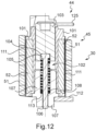
- the compact member 44 comprises a bobbin 101, a guide 107, a spring 108, an insulating sheath 111 and connection rods 125 and 125a implementing here the conductors 46 and 47.
- the trigger relay coil 52 is wound around the insulating plastic bobbin 101, which is generally tubular in shape with a flange at the end seen at the bottom in the drawings and, on the side seen at the top, a flange combined with housings each provided for one of the ends of the coil 52 and one of the rods 125 and 125a.
- the insulating sheath 111 is disposed between the magnetic trigger coil 51 and the trigger relay coil 52.
- the core 103, the striker 102, the spring 108 and the guide 107 are housed in the internal space of the coil 101.
- the core 103 is generally cylindrical in shape.
- a housing 104 is provided in one of its end portions.
- the core 103 is slidably mounted in the bobbin 101.
- the guide 107 is fixedly mounted in the bobbin 101, on one of its ends.
- a through bore 113 is provided in the guide 107.
- the striker 102 is formed by a rod-shaped body 106 and by a head 105 located at one end of the rod and projecting from it.
- the housing 104 is configured to receive the head 105 of the firing pin 102.
- the bore 113 of the guide 107 is configured to receive the rod 106.
- the spring 108 is arranged around the rod 106 of the firing pin 102.
- the connecting rod 125 is arranged between the end 110 of the trigger relay coil 52 and the electronic circuit 43a (see in particular the figure 13 ). Similarly, the connecting rod 125a is arranged between the end 110a of the trigger relay coil 52 and the electronic circuit 43a.
- the mechanical and electrical connecting piece 112 which is made of relatively rigid conductive material, is used for mounting the compact member 44 on the housing of the device 100 and for implementing the electrical connection between the magnetic trigger coil 51 and the fixed contact 31.
- the core 103 is held at a distance from the guide 107 by the spring 108.
- the flux created by the coil 51 or the coil 52 acts on the core 103 to cause it to slide in the bore 113, against the spring 108, towards the guide 107, which causes the striker 102 to protrude its rod 106 which then acts on the control mechanism 50.
- the compact member 44 and the lock 50 are straddled on an insulating partition 109.
- This partition 109 is provided between the routing circuit of the protected pole (between terminals 22 and 26) and the unprotected pole circuit (between terminals 23 and 27).
- the device 100 further comprises a differential fault detection transformer 35, the electronic circuit 43a is replaced by an electronic circuit 43d and the assembly formed by the trigger relay 45 connected to the electronic circuit 43d is further configured to act on the lock 50 not only in the event of prolonged overcurrent but also in the event of a differential fault.
- the current path circuit between terminals 22 and 26 comprises in series the magnetic triggering member 30, the fixed contact 31, the movable contact 32 and a winding 34 forming part of the transformer 35 and the path circuit between terminals 23 and 27 comprises in series the fixed contact 36, the movable contact 37 and a winding 38 forming part of the differential fault detection transformer 35.
- the transformer 35 comprises, in addition to the winding 34 and the winding 38, a secondary winding 39 and an annular armature 40 around which the secondary winding 39 and the primary windings 34 and 38 are made.
- the secondary winding 39 is connected by two conductors 41, 42 to the electronic circuit 43d which processes the differential fault signal supplied by the transformer 35 in addition to the signal representative of the intensity of the current supplied by the coil 52.
- the electronic circuit 43d is similar to the electronic circuit 43a except that the prolonged overcurrent detector 60 is replaced by an assembly formed by the interface 70, by the converter 71, by the calculation unit 72, by the monitoring unit 73, this assembly serving to determine the effective value of the intensity of the current flowing in the magnetic trigger coil 51; and except that it further comprises a switching interface 63 which produces the signals to which the switching circuit 61 responds.
- the switching interface 63 comprises two connection points 170 and 171 respectively connected by the conductors 42 and 41 to the secondary winding 39 of the transformer 35 and two output connection points 168 and 169 each connected to the switching circuit 61.
- the output connection point 168 is connected to the control connection points 93 and 94, respectively of the third switching member 81 and fourth switching member 82; and the output connection point 169 is connected to the control connection points 87 and 88, respectively of the first switching member 79 and second switching member 80.
- the interface 63 When a differential fault signal is provided by the transformer 35 on the conductors 41 and 42, the interface 63 produces in response a detection signal transmitted to the third switching member 81 and to the fourth switching member 82 then produces an actuation signal transmitted to the first switching member 79 and to the second switching member 80.
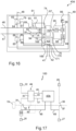
- FIG. 17 illustrates another variation of the device shown on the figures 4 to 14 .
- the device 100 further comprises a thermal trigger member 33 and the electronic circuit 43a is replaced by an electronic circuit 43b.
- the electronic circuit 43b is, in the same way as the electronic circuit 43a of the embodiment shown in the Figure 4 , connected to the trigger relay coil 52 by conductor 46 and by conductor 47.
- the current flow circuit between terminals 22 and 26 here comprises in series the magnetic trigger member 30, the fixed contact 31, the movable contact 32 and the thermal trigger member 33.
- the current flow circuit between terminals 23 and 27 remains unchanged.
- the thermal tripping member 33 is configured to automatically act on the lock 50 to move from the engaged position to the disconnected position when a prolonged overcurrent occurs.
- the thermal trigger member 33 is formed by a bimetallic strip which deforms in the event of prolonged overcurrent and acts due to its deformation on the lock 50.
- the electronic circuit 43b is similar to the electronic circuit 43a except that it does not include the switching circuit 61 or the monitoring unit 73, the prolonged overcurrent detector 60 being replaced by the assembly formed by the interface 70, by the converter 71 and by the calculation unit 72, this assembly being used to determine the effective value of the intensity of the current flowing in the magnetic trigger coil 51.
- the calculation unit 72 provides the digital values representative of the effective value of the current intensity only to the radiofrequency communication device 96 via the port 66.
- Interface 70 is connected directly to conductors 46 and 47.
- the device comprising the electronic circuit 43b shown in the figure 18 is configured so that the trigger relay coil 52 is used exclusively to supply the signal present at its ends 110 and 110a to the assembly formed by the interface 70, by the converter 71 and by the calculation unit 72, and not to drive the movable core 103 controlling the striker 102.
- FIG 19 illustrates another variation of the device shown on the figures 4 to 14 .
- the electrical circuit of the device is similar to that illustrated in the Figure 2 except that the electronic card 43 is replaced by the electronic circuit 43c.
- the device comprises a thermal tripping member 33 and a differential fault transformer 35
- the electronic circuit 43c is connected to the tripping relay coil by the conductor 46 and by the conductor 47
- the current path circuit between the terminals 22 and 26 comprises in series the magnetic tripping member 30, the fixed contact 31, the movable contact 32
- the path circuit between the terminals 23 and 27 comprises in series the fixed contact 36, the movable contact 37 and a winding 38 forming part of the differential fault detection transformer 35.
- the electronic circuit 43c is similar to the electronic circuit 43a except that it does not include the monitoring unit 73, the prolonged overcurrent detector 60 being replaced by the assembly formed by the interface 70, by the converter 71 and by the calculation unit 72, this assembly being used to determine the effective value of the intensity of the current flowing in the magnetic trigger coil 51; and except that it also includes a switching interface 63 which produces the signals to which the switching circuit 61 responds.
- the switching interface 63 comprises two connection points 170 and 171 respectively connected by the conductors 42 and 41 to the secondary winding 39 of the transformer 35 and two output connection points 168 and 169 each connected to the switching circuit 61.
- the output connection point 168 is connected to the control connection points 93 and 94, respectively of the third switching member 81 and fourth switching member 82; and the output connection point 169 is connected to the control connection points 87 and 88, respectively of the first switching member 79 and second switching member 80.
- the interface 63 is configured to produce the detection signal and then to produce, after a predetermined time after the start of production of the detection signal, the actuation signal.
- the interface 63 transmits the detection signal to the switching circuit 61 via its output connection point 168 and the actuation signal via its output point 169.
- the interface 63 When a differential fault signal is provided by the transformer 35 on the conductors 41 and 42, the interface 63 produces in response a detection signal transmitted to the third switching member 81 and to the fourth switching member 82 then produces an actuation signal transmitted to the first switching member 79 and to the second switching member 80.
- the protective device has a different width and/or a different number of poles, for example a four-pole device with a width of four modules comprising four terminals in the upper part and four terminals in the lower part.
Landscapes
- Physics & Mathematics (AREA)
- Electromagnetism (AREA)
- Engineering & Computer Science (AREA)
- Power Engineering (AREA)
- Emergency Protection Circuit Devices (AREA)
- Relay Circuits (AREA)
- Breakers (AREA)
Applications Claiming Priority (2)
| Application Number | Priority Date | Filing Date | Title |
|---|---|---|---|
| FR1911518A FR3102293B1 (fr) | 2019-10-16 | 2019-10-16 | Appareil de protection d’une installation électrique en courant alternatif |
| EP20202252.1A EP3809441B1 (de) | 2019-10-16 | 2020-10-16 | Schutzgerät einer elektrischen anlage mit wechselstrom |
Related Parent Applications (1)
| Application Number | Title | Priority Date | Filing Date |
|---|---|---|---|
| EP20202252.1A Division EP3809441B1 (de) | 2019-10-16 | 2020-10-16 | Schutzgerät einer elektrischen anlage mit wechselstrom |
Publications (2)
| Publication Number | Publication Date |
|---|---|
| EP4546391A2 true EP4546391A2 (de) | 2025-04-30 |
| EP4546391A3 EP4546391A3 (de) | 2025-07-23 |
Family
ID=69375507
Family Applications (2)
| Application Number | Title | Priority Date | Filing Date |
|---|---|---|---|
| EP25163085.1A Pending EP4546391A3 (de) | 2019-10-16 | 2020-10-16 | Schutzvorrichtung für eine elektrische wechselstromanlage |
| EP20202252.1A Active EP3809441B1 (de) | 2019-10-16 | 2020-10-16 | Schutzgerät einer elektrischen anlage mit wechselstrom |
Family Applications After (1)
| Application Number | Title | Priority Date | Filing Date |
|---|---|---|---|
| EP20202252.1A Active EP3809441B1 (de) | 2019-10-16 | 2020-10-16 | Schutzgerät einer elektrischen anlage mit wechselstrom |
Country Status (6)
| Country | Link |
|---|---|
| EP (2) | EP4546391A3 (de) |
| CN (1) | CN112670943B (de) |
| AU (1) | AU2020256419B2 (de) |
| ES (1) | ES3033471T3 (de) |
| FR (1) | FR3102293B1 (de) |
| PL (1) | PL3809441T3 (de) |
Families Citing this family (2)
| Publication number | Priority date | Publication date | Assignee | Title |
|---|---|---|---|---|
| GB2637358A (en) * | 2024-01-19 | 2025-07-23 | Eaton Intelligent Power Ltd | Health monitoring of electromagnetic relay |
| WO2025153722A1 (en) * | 2024-01-19 | 2025-07-24 | Eaton Intelligent Power Limited | Health monitoring of electromagnetic relay |
Citations (1)
| Publication number | Priority date | Publication date | Assignee | Title |
|---|---|---|---|---|
| FR3046289A1 (fr) | 2015-12-29 | 2017-06-30 | Legrand France | Appareil electrique de protection au format modulaire |
Family Cites Families (8)
| Publication number | Priority date | Publication date | Assignee | Title |
|---|---|---|---|---|
| US3566189A (en) * | 1969-03-18 | 1971-02-23 | Airpax Electronics | Circuit breaker with loosely coupled deenergizing means for high overload currents |
| DE19963504C1 (de) * | 1999-12-28 | 2001-10-18 | Tyco Electronics Logistics Ag | Relais mit Überstromschutz |
| US6538870B2 (en) * | 2001-02-02 | 2003-03-25 | Eaton Corporation | Circuit breaker and electrical distribution panel employing the same |
| CN100517896C (zh) * | 2006-07-24 | 2009-07-22 | 苏州松宝电气有限公司 | 接地故障断路器的控制电路 |
| US20090021879A1 (en) * | 2007-07-17 | 2009-01-22 | Rivers Jr Cecil | Apparatus and method for fault current interruption |
| AT506092B1 (de) * | 2008-08-13 | 2009-06-15 | Siemens Ag Oesterreich | Elektrische anlage |
| US8681466B2 (en) * | 2009-05-08 | 2014-03-25 | Rockwell Automation Technologies, Inc. | Magnetic core coupling in a current transformer with integrated magnetic actuator |
| BR112017004343A2 (pt) * | 2014-09-05 | 2017-12-05 | Ethicon Llc | fonte de alimentação modular com proteção contra sobrecorrente para dispositivo médico |
-
2019
- 2019-10-16 FR FR1911518A patent/FR3102293B1/fr active Active
-
2020
- 2020-10-16 AU AU2020256419A patent/AU2020256419B2/en active Active
- 2020-10-16 CN CN202011112675.7A patent/CN112670943B/zh active Active
- 2020-10-16 PL PL20202252.1T patent/PL3809441T3/pl unknown
- 2020-10-16 EP EP25163085.1A patent/EP4546391A3/de active Pending
- 2020-10-16 EP EP20202252.1A patent/EP3809441B1/de active Active
- 2020-10-16 ES ES20202252T patent/ES3033471T3/es active Active
Patent Citations (1)
| Publication number | Priority date | Publication date | Assignee | Title |
|---|---|---|---|---|
| FR3046289A1 (fr) | 2015-12-29 | 2017-06-30 | Legrand France | Appareil electrique de protection au format modulaire |
Also Published As
| Publication number | Publication date |
|---|---|
| FR3102293B1 (fr) | 2021-11-12 |
| AU2020256419B2 (en) | 2025-04-17 |
| PL3809441T3 (pl) | 2025-08-04 |
| AU2020256419A1 (en) | 2021-05-06 |
| EP3809441B1 (de) | 2025-04-02 |
| ES3033471T3 (en) | 2025-08-04 |
| EP3809441A1 (de) | 2021-04-21 |
| EP3809441C0 (de) | 2025-04-02 |
| FR3102293A1 (fr) | 2021-04-23 |
| EP4546391A3 (de) | 2025-07-23 |
| CN112670943A (zh) | 2021-04-16 |
| CN112670943B (zh) | 2026-01-20 |
Similar Documents
| Publication | Publication Date | Title |
|---|---|---|
| EP0264314B1 (de) | Mehrpoliger Differentialmodulschutzschalter | |
| EP3267462B1 (de) | Verbindungsmodul eines schutzschalters und eines kontaktschalters für eine elektrische einheit | |
| EP3267461B1 (de) | Verbindungsmodul eines schutzschalters und eines kontaktschalters für eine elektrische einheit, die einen spannungsaufnehmer umfasst | |
| EP0320411A1 (de) | Fehlerstromschutzschalter | |
| FR3010531A1 (fr) | Procede de determination d'une cause de perte de tension en aval d'un disjoncteur, appareil auxiliaire pour disjoncteur, systeme electrique comportant un disjoncteur et un tel appareil auxiliaire | |
| EP3809441B1 (de) | Schutzgerät einer elektrischen anlage mit wechselstrom | |
| EP0199612B1 (de) | Mehrpoliges Schaltgerät mit Fernsteuerung | |
| EP3267209B1 (de) | Messgerät für elektrische ströme in elektrischen leitern | |
| EP3809440B1 (de) | Schutzgerät einer elektrischen anlage mit wechselstrom | |
| EP0649158A1 (de) | Differentialschutzblock mit Kabeldurchgang | |
| EP3709333B1 (de) | Elektrisches gerät zur versorgung oder nichtversorgung einer last in abhängigkeit vom ein- oder aus-zustand eines bedienorgans | |
| FR2752479A1 (fr) | Disjoncteur differentiel electronique | |
| EP2743958B1 (de) | Elektrisches Stromschaltgerät, insbesondere Abzweigschalter | |
| EP4068327B1 (de) | Elektrisches gerät, mit dem eine wechselstromquelle je nach den über eine funkfrequenz empfangenen befehlen eine last speisen kann oder nicht, und schaltkreis mit diesem gerät | |
| EP4435829B1 (de) | Zusatzmodul zur detektion eines elektrischen fehlers und elektrische schutzanordnung mit einem solchen zusatzmodul zur detektion eines elektrischen fehlers | |
| EP0079270B1 (de) | Niederspannungsabzweigschalter mit einem ferngesteuerten Einstellschalter | |
| EP4016777B1 (de) | Stromschutzgerät einer elektrischen anlage mit wechselstrom | |
| FR3016078A1 (fr) | Appareil electrique au format modulaire | |
| FR2675318A1 (fr) | Systeme de protection de circuits electriques. | |
| EP2743957B1 (de) | Gerät zur Stromunterbrechung, insbesondere Anschluss-Überlastschalter | |
| EP2743956A1 (de) | Gerät zur Stromunterbrechung, insbesondere Anschluss-Überlastschalter | |
| FR3054383A1 (fr) | Tableau de protection electrique | |
| EP0362085A1 (de) | Schaltgerät mit Fernsteuerung |
Legal Events
| Date | Code | Title | Description |
|---|---|---|---|
| PUAI | Public reference made under article 153(3) epc to a published international application that has entered the european phase |
Free format text: ORIGINAL CODE: 0009012 |
|
| STAA | Information on the status of an ep patent application or granted ep patent |
Free format text: STATUS: THE APPLICATION HAS BEEN PUBLISHED |
|
| AC | Divisional application: reference to earlier application |
Ref document number: 3809441 Country of ref document: EP Kind code of ref document: P |
|
| AK | Designated contracting states |
Kind code of ref document: A2 Designated state(s): AL AT BE BG CH CY CZ DE DK EE ES FI FR GB GR HR HU IE IS IT LI LT LU LV MC MK MT NL NO PL PT RO RS SE SI SK SM TR |
|
| REG | Reference to a national code |
Ref country code: DE Ref legal event code: R079 Free format text: PREVIOUS MAIN CLASS: H01H0071740000 Ipc: H01H0071040000 |
|
| PUAL | Search report despatched |
Free format text: ORIGINAL CODE: 0009013 |
|
| AK | Designated contracting states |
Kind code of ref document: A3 Designated state(s): AL AT BE BG CH CY CZ DE DK EE ES FI FR GB GR HR HU IE IS IT LI LT LU LV MC MK MT NL NO PL PT RO RS SE SI SK SM TR |
|
| RIC1 | Information provided on ipc code assigned before grant |
Ipc: H01H 71/04 20060101AFI20250617BHEP Ipc: H01H 71/12 20060101ALI20250617BHEP Ipc: H01H 71/24 20060101ALI20250617BHEP Ipc: H01H 71/74 20060101ALI20250617BHEP Ipc: H01H 73/64 20060101ALN20250617BHEP |