EP4546151A1 - Rechnersystem und datentransportsystem - Google Patents
Rechnersystem und datentransportsystem Download PDFInfo
- Publication number
- EP4546151A1 EP4546151A1 EP24170179.6A EP24170179A EP4546151A1 EP 4546151 A1 EP4546151 A1 EP 4546151A1 EP 24170179 A EP24170179 A EP 24170179A EP 4546151 A1 EP4546151 A1 EP 4546151A1
- Authority
- EP
- European Patent Office
- Prior art keywords
- transport
- data
- devices
- paths
- target device
- Prior art date
- Legal status (The legal status is an assumption and is not a legal conclusion. Google has not performed a legal analysis and makes no representation as to the accuracy of the status listed.)
- Pending
Links
Images




Classifications
-
- H—ELECTRICITY
- H04—ELECTRIC COMMUNICATION TECHNIQUE
- H04L—TRANSMISSION OF DIGITAL INFORMATION, e.g. TELEGRAPHIC COMMUNICATION
- H04L49/00—Packet switching elements
- H04L49/25—Routing or path finding in a switch fabric
-
- H—ELECTRICITY
- H04—ELECTRIC COMMUNICATION TECHNIQUE
- H04L—TRANSMISSION OF DIGITAL INFORMATION, e.g. TELEGRAPHIC COMMUNICATION
- H04L49/00—Packet switching elements
- H04L49/10—Packet switching elements characterised by the switching fabric construction
- H04L49/109—Integrated on microchip, e.g. switch-on-chip
-
- H—ELECTRICITY
- H04—ELECTRIC COMMUNICATION TECHNIQUE
- H04L—TRANSMISSION OF DIGITAL INFORMATION, e.g. TELEGRAPHIC COMMUNICATION
- H04L45/00—Routing or path finding of packets in data switching networks
- H04L45/24—Multipath
-
- G—PHYSICS
- G06—COMPUTING OR CALCULATING; COUNTING
- G06F—ELECTRIC DIGITAL DATA PROCESSING
- G06F15/00—Digital computers in general; Data processing equipment in general
- G06F15/76—Architectures of general purpose stored program computers
- G06F15/78—Architectures of general purpose stored program computers comprising a single central processing unit
- G06F15/7807—System on chip, i.e. computer system on a single chip; System in package, i.e. computer system on one or more chips in a single package
- G06F15/7825—Globally asynchronous, locally synchronous, e.g. network on chip
-
- H—ELECTRICITY
- H04—ELECTRIC COMMUNICATION TECHNIQUE
- H04L—TRANSMISSION OF DIGITAL INFORMATION, e.g. TELEGRAPHIC COMMUNICATION
- H04L49/00—Packet switching elements
- H04L49/10—Packet switching elements characterised by the switching fabric construction
- H04L49/101—Packet switching elements characterised by the switching fabric construction using crossbar or matrix
-
- H—ELECTRICITY
- H04—ELECTRIC COMMUNICATION TECHNIQUE
- H04L—TRANSMISSION OF DIGITAL INFORMATION, e.g. TELEGRAPHIC COMMUNICATION
- H04L49/00—Packet switching elements
- H04L49/10—Packet switching elements characterised by the switching fabric construction
- H04L49/112—Switch control, e.g. arbitration
-
- H—ELECTRICITY
- H04—ELECTRIC COMMUNICATION TECHNIQUE
- H04L—TRANSMISSION OF DIGITAL INFORMATION, e.g. TELEGRAPHIC COMMUNICATION
- H04L49/00—Packet switching elements
- H04L49/15—Interconnection of switching modules
- H04L49/1553—Interconnection of ATM switching modules, e.g. ATM switching fabrics
- H04L49/1576—Crossbar or matrix
Definitions
- a conventional NoC (Network on Chip) system may comprise a plurality of routers, such that the NoC system can receive input data and transport the input data to a node via the routers.
- transport delay may be caused when the data is input to the router or when the data is output by the router. Accordingly, if the transport of data goes through many routers, a large data transport delay may be caused.
- One objective of the present application is to provide a computing system which can reduce transport delay.
- Another objective of the present application is to provide a data transport system which can reduce transport delay.
- a data transport system according to the invention is defined in claim 1.
- a computing system according to the invention is defined in claim 2.
- the further dependent claims define preferred embodiments thereof.
- One embodiment of the present application discloses a computing system, which comprises: a plurality of routers, configured to transport data to nodes; a plurality of transport stations, configured to transport the data to the nodes or to the routers; a plurality of first paths, provided between adjacent ones of the routers; a plurality of second paths, provided between adjacent ones of the transport stations.
- the computing system operates in a first mode, which transmits the data from a first target device to a second target device via the first paths and the second paths during a first time interval.
- the first target device is one of the routers or one of the nodes
- the second target device is one of the routers or one of the nodes.
- a data transport system comprising: a plurality of first transport devices, configured to transport data to destination devices; a plurality of second transport devices, configured to transport the data to the destination devices or to the first transport devices; a plurality of first paths, provided between adjacent ones of the first transport devices; a plurality of second paths, provided between adjacent ones of the second transport devices.
- the data transport system selectively operates in a first mode, which transmits the data from a first target device to a second target device via the first paths and the second paths during a second time interval.
- the first target device is one of the first transport devices or one of the destination devices
- the second target device is one of the first transport devices or one of the destination devices.
- the transport delay can be reduced, since the data can be transported by a shortcut formed by the transport stations rather than limited to be transported by a path only formed by routers.
- FIG.1 is a schematic diagram illustrating a portion of a computing system according to one embodiment of the present application.
- FIG.2 is a schematic diagram illustrating a more complete structure of the computing system illustrated in FIG.1 .
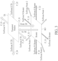
- FIG.3 is a schematic diagram illustrating the paths of the transport station or the router, which correspond to different directions, according to one embodiment of the present application.
- FIG.4 , FIG.5 , FIG.6 and FIG.7 are schematic diagrams illustrating details of the transport station or the router, according to different embodiments of the present application.
- FIG.8 is a block diagram illustrating a super computer system, according to one embodiment of the present application.
- first, second, third in following descriptions are only for the purpose of distinguishing different elements, and do not mean the sequence of the elements.
- a first device and a second device only mean these devices can have the same structure but are different devices.
- data in following embodiments can mean any signal or any information which can be used for electronic devices.
- FIG.1 is a schematic diagram illustrating a portion of a computing system according to one embodiment of the present application.
- FIG.2 is a schematic diagram illustrating a more complete structure of the computing system illustrated in FIG.1 . Please refer to FIG.1 while referring to FIG.2 , to understand the concepts of the present application for more clarity.
- the computing system 100 comprises a plurality of routers (four routers RO_1, RO_2, RO_3 and RO_4 are symbolized for explaining) .
- the routers are configured to transport data to nodes (four nodes NO_1, NO_2, NO_3 and NO_4 are symbolized for explaining).
- the node can be any electronic device which can receive data, such as a CPU or a GPU.
- each router corresponds to one node.
- the router RO_1 is configured to output data to the node NO_1 and the router RO_2 is configured to output data to the node NO_2.
- the router may correspond more than one node.
- the router may only transport data but does not output data to any node.
- first paths are provided between adjacent routers. For example, a first path is provided between the router RO_1 and the router RO_2 and a first path is provided between the router RO_1 and the router RO_3.
- the adjacent routers mean that no other router is needed while transporting data between two adjacent routers.
- routers RO_1 and RO_2 are adjacent routers and routers RO_3 and RO_4 are adjacent routers, but routers RO_1 and RO_3 are not adjacent routers.
- the transport times of all first paths are the same.
- the transport times of different first paths are different. For example, transport time of the first path between routers RO_1 and RO_2 and transport time of the first path between routers RO_3 and RO_4 are different.
- FIG.2 is a schematic diagram illustrating a more complete structure of the computing system illustrated in FIG.1 .
- the embodiment in FIG.2 further comprises a plurality of transport stations.
- Four transport stations TR_1 to TR_4 are used as examples for explaining.
- the transport stations TR_1 to TR_4 are configured to transport the data to the nodes through the routers.
- the transport station TR_1 may transport the data to the node NO_5 or to the router RO_5.
- Second paths are provided between adjacent transport stations.
- a second path is provided between the transport station TR_1 and the transport station TR_2, and a second path is provided between transport station TR_2 and the transport station TR_3.
- the adjacent transport stations mean that no other transport station is needed while transporting data between two adjacent transport stations.
- the transport stations TR_1 to TR_4 are adjacent transport stations for each other.
- the transport times of all second paths are the same.
- the transport times of different second paths are different. For example, the transport time of the second path between transport stations TR_1 and TR_2 and the transport time of the second path between transport stations TR_3 and TR_4 are different.
- the computing system 100 may adaptively select the first paths(second mode), the second paths(third mode) and the combination (first mode) with a shorter time interval to transmit data from a first target device to a second target device according to the locations where the first target device and the second target device situated in.
- the first device and the second device may be one of the nodes or routers.
- the computing system operates in a first mode, which transmits the data from a first target device to a second target device via the first paths and the second paths during a first time interval.
- a second path may replace a plurality of first paths.
- a second path between the transport stations TR_1 and TR_2 may replace a plurality of first paths of the routers between the transport stations TR_1 and TR_2. Accordingly, less routers are needed while using the second paths to replace the first paths.
- the computing system may operate in a second mode, which transmits the data from the first target device to the second target device via the first paths without the second paths during a second time interval which is shorter than the first time interval.
- the first target device and the second target device may be a router or a node.
- the computing system 100 may transmit the data from the router RO_5 to the router RO_6 via a first route 101 with the first paths and the second paths in a first time interval in a first mode.
- the data have to been delivered from the router RO_5 to the router RO_6 via two routers and two transport stations TR_2 and TR_3.
- the computing system 100 may transmit the data from the router RO_5 to the router RO_6 via a second route 102 with the first paths but without the second paths during a second time interval in a second mode.
- the data have to been delivered from the router RO_5 to the router RO_6 via eight routers.
- the first time interval of the first route 101 is shorter than the second time interval of the second route 102 since the midway stations (routers or transportation station) in the first route 101 is less than that of the second route 102. Therefore, the computing system would select the first route 101 to transmit data from the router RO_5 to the router RO_6.
- the first time interval of the first route is larger than the second time interval of the second route. In such case, the second route is selected to transmit data.
- the routers are classified into a plurality of system groups SG_1...SG_4 according to locations of the routers.
- the location may mean physical locations or access addresses of the routers.
- the number of the system groups can be any other number rather than limited to 4.
- the computing system 100 operates in one of the first mode, the second mode and the third mode according to the system group which the first target device and the second target device are located in. For example, if the first target device and the second target device are both in the system group SG_1, the computing system 100 operates in the second mode since no suitable second path can be used.
- the data is transmitted to the transport station TR_1 first and then transmitted to the transport station TR_3 via the second path. After that, the data is transmitted to the second target device from the transport station TR_3.
- FIG.3 is a schematic diagram illustrating the paths of the transport station or the router, which correspond to different directions, according to different embodiments of the present application.
- the structure of paths of the transport station TS and the router RO is not limited to the structure shown in FIG.3 .
- the transport station TS and the router RO are illustrated as a 3D diagram.
- the transport station TS and the router RO are provided in different planes.
- the transport station TS and the router RO can be provided in the same plane.
- the first paths P_12, P_13, P_14 and P_11 may respectively have different directions: East, South, West and North. Please note, the directions "East, South, West and North” mentioned here are only used for representing different directions but do not mean geographical directions. Accordingly, the first paths P_12, P_13, P_14 and P_11 are respectively to/from routers in the East, South, West and North (herein after, E router, S router, W router and N router) . Following the same rule, the second paths P_22, P_23, P_24 and P_21 are respectively to/from transport stations in the East, South, West and North (herein after, E TS, S TS, W TS and N TS). Also, paths P_31, P_32 are provided between the transport station TS and the router RO, such that data can be transmitted between the transport station TS and the router RO. Additionally, the router RO may further comprise paths to and from the nodes 0-3.
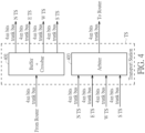
- FIG.4 , FIG.5 , FIG.6 and FIG.7 are schematic diagrams illustrating details of the transport station or the router, according to different embodiments of the present application.
- the transport station TS comprises a device 401 which comprises at least one cross bar switch and at least one buffer.
- the crossbar switch which is provided between the transport station TS and at least one router, is configured to change a switch state thereof to transport the data from the router to the transport stations N TS, E TS, W TS or the S TS.
- the buffer which is provided between the transport station TS and the router, is configured to buffer the data from the router to the transport station N TS, E TS, W TS or the S TS.
- the arbiter 403 which is provided between the transport station N TS, E TS, W TS or the S TS and the router, is configured to allocate the data from the transport station N TS, E TS, W TS or the S TS to the router.
- the arbiter 403 is a TDM (Time-Division Multiplexing) arbiter.
- the second paths between transport stations TS and N TS, E TS, W TS or the S TS are 4n bits trunk buses and the paths between the transport station TS and a router is a 4n bits trunk bus as well.
- the computing system transmits the data from one of the nodes to another one of the nodes via at least one physical channel (PC).
- PC physical channel
- the data from a node N0 to a node N1 is transmitted to the router RO via a physical channel N0 PC and then transmitted from the router RO to the node N1 via a physical channel N1 PC.
- the physical channel means real and physical channel, such as a transmission line or a bus.
- the computing system transmits the data from one of the routers to another one of the routers via at least one virtual channel.
- the data from an E router to a W router is transmitted to the router RO via a virtual channel E VC and then transmitted from the router RO to the W router via a virtual channel W VC.
- a virtual channel (VC) is a communications track between two devices giving the bandwidth needed for a virtual connection.
- the bandwidth of the virtual channel is smaller than which of the physical channel, thus more virtual channels may be combined to form a single virtual channel.
- FIG.6 is a schematic diagram illustrating how the data is transported by the computing system, according to one embodiment of the present application.
- the transport station TS comprises a plurality of output buffers, such as W buffer, N buffer, E buffer and S buffer.
- the router RO comprises multiplexers 601, 603, an arbiter 605 and a router buffer.
- the data is transmitted in a packet format, such as the packets PA_1, PA_2 in FIG.6 .
- the symbols in the packets represent destinations which the packet are supposed to be transported to.
- the packet PA_1 is supposed to be transported to the system group SG_1 in FIG.2 and the packet PA_2 is supposed to be transported to the system group SG_3 in FIG.2 .
- the arbiter 605 is a TDM arbiter, thus the router buffer stores the packets from the E, W, N, S routers, and then the multiplexer 601 selectively outputs these packets at times T0, T2, T4 and T6.
- a node buffer is also comprised in the embodiment of FIG.6 .
- the node buffer stores the packets from the nodes 0, 1, 2, 3 and then the multiplexer 603 selectively outputs these packets at times T1, T3, T5 and T7.
- the sequence of times T1-T7 is T1, T2, T3, T4, T5, T6, T7.
- the data output by the arbiter 605 is stored to the output buffers corresponding to the destinations of the data.
- the destination of the packet PA_1 is the system group SG1, and should be transported by the transport station E TS, thus is stored to the output buffer E buffer corresponding to the transport station E TS at the time T0.
- the destination of the packet PA_2 is the system group SG3, and should be transported by the transport station N TS, thus is stored to the output buffer N buffer corresponding to the transport station N TS at the time T1.
- the paths in FIG.6 may have different bandwidths.
- the paths between routers may be n bits local buses, and the paths of the multiplexers 601, 603 and the arbiter 605 are 4n bits trunk buses.
- the paths between transport stations(e.g., the second paths) may be 4n bits trunk buses. Accordingly, in the embodiment of FIG.6 , bandwidths of the second paths between adjacent transport stations are larger than bandwidths of the first paths between adjacent routers.
- the data is from routers or nodes to the transport stations.
- the transport direction of data is opposite to which of the FIG.6 . That is, the data is from transport stations to the routers or nodes.
- the router RO also comprises multiplexers 601, 603 and the arbiter 605, and the transport station TS comprises a TDM arbiter 701.
- the TDM arbiter 701 selectively outputs data from the transport stations W TS, N TS, E TS, and the S TS to the arbiter 605.
- the arbiter 605 selectively outputs data to the multiplexer 601 or 603.
- the multiplexer 601 selectively outputs data to the E router, the W router, the N router or the S router.
- the multiplexer 603 selectively outputs data to the node 0, node 1, node 2, or the node 3.
- the computing system is an NoC system. Accordingly, the routers, the transport stations, the first paths and the second paths are provided in a single chip.
- the computing system disclosed in the present application can be applied to a multi-chip system, which can be a super computer system.
- FIG.8 is a block diagram illustrating a super computer system 800, according to one embodiment of the present application.
- a plurality of transport stations TS are disposed in different chips ch1-ch15.
- the chips ch1-ch15 are provided in at least two computers.
- the transport stations TS may be connected by different cables, such as the cables Ca_1...Ca_4 in FIG.8 .
- the operations of FIG.8 are similar with which of above-mentioned embodiments.
- the data may be transmitted between different transport stations, and then transported to the routers in different chips or transported to nodes which are connected to the transport stations TS.
- the computing system provided by the present application may be summarized as a computing system comprising a plurality of routers, a plurality of transport stations, a plurality of first paths and a plurality of second paths.
- the routers are configured to transport data to nodes.
- the transport stations are configured to transport the data to the nodes or to the routers.
- First paths are provided between adjacent ones of the routers.
- Second paths are provided between adjacent ones of the transport stations.
- the computing system selectively operates in a first mode, which transmits the data from a first target device to a second target device via the first paths and the second paths during a first time interval.
- the first target device is one of the routers or one of the nodes
- the second target device is one of the routers or one of the nodes.
- a computing system which comprises routers for transporting data to nodes
- the NoC system a single chip system
- the concept disclosed by the present invention may be implemented to any data transport system rather than a computing system comprising routers for transporting data to nodes.
- the router is replaced by a "first transport device”
- the transport station is replaced by a "second transport device”.
- the node is replaced by a "destination device”.
- the transport delay can be reduced, since the data can be transported by a shortcut formed by the transport stations rather than limited to be transported by a path only formed by routers.
Landscapes
- Engineering & Computer Science (AREA)
- Computer Networks & Wireless Communication (AREA)
- Signal Processing (AREA)
- Physics & Mathematics (AREA)
- Computer Hardware Design (AREA)
- Mathematical Physics (AREA)
- General Engineering & Computer Science (AREA)
- Theoretical Computer Science (AREA)
- Computing Systems (AREA)
- Microelectronics & Electronic Packaging (AREA)
- General Physics & Mathematics (AREA)
- Data Exchanges In Wide-Area Networks (AREA)
Applications Claiming Priority (1)
| Application Number | Priority Date | Filing Date | Title |
|---|---|---|---|
| US18/383,481 US20250141817A1 (en) | 2023-10-25 | 2023-10-25 | Computing system and data transport system |
Publications (1)
| Publication Number | Publication Date |
|---|---|
| EP4546151A1 true EP4546151A1 (de) | 2025-04-30 |
Family
ID=90731523
Family Applications (1)
| Application Number | Title | Priority Date | Filing Date |
|---|---|---|---|
| EP24170179.6A Pending EP4546151A1 (de) | 2023-10-25 | 2024-04-15 | Rechnersystem und datentransportsystem |
Country Status (4)
| Country | Link |
|---|---|
| US (1) | US20250141817A1 (de) |
| EP (1) | EP4546151A1 (de) |
| CN (1) | CN119892719A (de) |
| TW (1) | TWI866764B (de) |
Family Cites Families (15)
| Publication number | Priority date | Publication date | Assignee | Title |
|---|---|---|---|---|
| US5774067A (en) * | 1995-06-07 | 1998-06-30 | International Business Machines Corporation | Flash-flooding multi-stage interconnection network with parallel path seeking switching elements |
| US5987028A (en) * | 1997-05-12 | 1999-11-16 | Industrial Technology Research Insitute | Multiple channel ATM switch |
| US6591285B1 (en) * | 2000-06-16 | 2003-07-08 | Shuo-Yen Robert Li | Running-sum adder networks determined by recursive construction of multi-stage networks |
| US7742486B2 (en) * | 2004-07-26 | 2010-06-22 | Forestay Research, Llc | Network interconnect crosspoint switching architecture and method |
| TW200835151A (en) * | 2007-02-15 | 2008-08-16 | Univ Nat Chiao Tung | Low-power dynamic sequential controlling multiplexer |
| US8407660B2 (en) * | 2007-09-12 | 2013-03-26 | Neal Solomon | Interconnect architecture in three dimensional network on a chip |
| KR20090031022A (ko) * | 2007-09-21 | 2009-03-25 | 삼성전자주식회사 | 온 칩 네트워크 제어 장치 및 방법 |
| JP4592800B2 (ja) * | 2009-03-12 | 2010-12-08 | パナソニック株式会社 | 経路選択装置、経路選択方法、およびプログラム |
| US9160617B2 (en) * | 2012-09-28 | 2015-10-13 | International Business Machines Corporation | Faulty core recovery mechanisms for a three-dimensional network on a processor array |
| US11469206B2 (en) * | 2018-06-14 | 2022-10-11 | Intel Corporation | Microelectronic assemblies |
| WO2020123796A1 (en) * | 2018-12-12 | 2020-06-18 | Interactic Holdings, Llc | Method and apparatus for improved data transfer between processor cores |
| WO2021105728A1 (en) * | 2019-11-28 | 2021-06-03 | Mellanox Technologies Ltd. | Efficient parallelized computation of a benes network configuration |
| DE102021107484A1 (de) * | 2021-03-25 | 2022-09-29 | Airbus Defence and Space GmbH | Kommunikationsverfahren in einem Network-on-Chip |
| US12469820B2 (en) * | 2021-12-10 | 2025-11-11 | Intel Corporation | Fine-grained disaggregated server architecture |
| CN117118902A (zh) * | 2022-04-29 | 2023-11-24 | 华为技术有限公司 | 一种通信芯片及数据交换装置 |
-
2023
- 2023-10-25 US US18/383,481 patent/US20250141817A1/en active Pending
-
2024
- 2024-01-29 CN CN202410123042.8A patent/CN119892719A/zh active Pending
- 2024-01-31 TW TW113103727A patent/TWI866764B/zh active
- 2024-04-15 EP EP24170179.6A patent/EP4546151A1/de active Pending
Non-Patent Citations (3)
| Title |
|---|
| FRANK CHANG M ET AL: "CMP network-on-chip overlaid with multi-band RF-interconnect", HIGH PERFORMANCE COMPUTER ARCHITECTURE, 2008. HPCA 2008. IEEE 14TH INTERNATIONAL SYMPOSIUM ON, IEEE, PISCATAWAY, NJ, USA, 16 February 2008 (2008-02-16), pages 191 - 202, XP031353633, ISBN: 978-1-4244-2070-4 * |
| RAPARTI VENKATA YASWANTH ET AL: "Memory-aware circuit overlay NoCs for latency optimized GPGPU architectures", 2016 17TH INTERNATIONAL SYMPOSIUM ON QUALITY ELECTRONIC DESIGN (ISQED), IEEE, 15 March 2016 (2016-03-15), pages 63 - 68, XP032905021, ISSN: 1948-3295, [retrieved on 20160525], DOI: 10.1109/ISQED.2016.7479177 * |
| VALADBEIGI MAJED ET AL: "An Energy-Efficient Reconfigurable NoC Architecture with RF-Interconnects", 2013 EUROMICRO CONFERENCE ON DIGITAL SYSTEM DESIGN, IEEE, 4 September 2013 (2013-09-04), pages 489 - 496, XP032502931, DOI: 10.1109/DSD.2013.58 * |
Also Published As
| Publication number | Publication date |
|---|---|
| US20250141817A1 (en) | 2025-05-01 |
| CN119892719A (zh) | 2025-04-25 |
| TWI866764B (zh) | 2024-12-11 |
| TW202518878A (zh) | 2025-05-01 |
Similar Documents
| Publication | Publication Date | Title |
|---|---|---|
| US11640362B2 (en) | Procedures for improving efficiency of an interconnect fabric on a system on chip | |
| US6628615B1 (en) | Two level virtual channels | |
| US6967926B1 (en) | Method and apparatus for using barrier phases to limit packet disorder in a packet switching system | |
| US7502378B2 (en) | Flexible wrapper architecture for tiled networks on a chip | |
| CA2020239C (en) | Interconnect fabric providing connectivity between an input and arbitrary output (s) of a group of outputs | |
| EP0471344A1 (de) | Verfahren und Schaltung zur Verkehrsformung | |
| US7889725B2 (en) | Computer cluster | |
| US4797880A (en) | Non-blocking, self-routing packet switch | |
| US20130235879A1 (en) | Method And Device For Managing Priority During The Transmission Of A Message | |
| EP0492025B1 (de) | Hochgeschwindigkeitsmultiport-FIFO-Pufferschaltung | |
| JPS61214694A (ja) | データ伝送のスイッチング装置 | |
| EP0415628A2 (de) | Erweitbare Paketvermittlungsarchitektur | |
| US5926475A (en) | Method and apparatus for ensuring ATM cell order in multiple cell transmission lane switching system | |
| EP1875683B1 (de) | Integrierte schaltung mit datenkommunikationsnetz und verfahren zum entwurf integrierter schaltungen | |
| US20250141817A1 (en) | Computing system and data transport system | |
| CA3123224C (en) | Method and apparatus for improved data transfer between processor cores | |
| Makedon et al. | Optimal algorithms for the many-to-one routing problem on two-dimensional meshes | |
| KR100378588B1 (ko) | 대용량화가 가능한 다중 경로 비동기 전송 모드 스위치 및 셀구조 | |
| Trigui et al. | Mesh 2D Network on Chip with an open core protocol based network interface | |
| KR930007017B1 (ko) | 인터커넥션 네트워크 스위칭소자 | |
| JPH06132976A (ja) | Atmスイッチエレメントおよびatmスイッチ | |
| JPH0779255A (ja) | パケット優先制御装置 | |
| JPH11297834A (ja) | セル間の通信方法 | |
| Inukai | Information Switching Processor (ISP) contention analysis and control | |
| Bahl et al. | Packet Switching–Queuing Architecture: A Study |
Legal Events
| Date | Code | Title | Description |
|---|---|---|---|
| PUAI | Public reference made under article 153(3) epc to a published international application that has entered the european phase |
Free format text: ORIGINAL CODE: 0009012 |
|
| STAA | Information on the status of an ep patent application or granted ep patent |
Free format text: STATUS: THE APPLICATION HAS BEEN PUBLISHED |
|
| AK | Designated contracting states |
Kind code of ref document: A1 Designated state(s): AL AT BE BG CH CY CZ DE DK EE ES FI FR GB GR HR HU IE IS IT LI LT LU LV MC ME MK MT NL NO PL PT RO RS SE SI SK SM TR |
|
| STAA | Information on the status of an ep patent application or granted ep patent |
Free format text: STATUS: REQUEST FOR EXAMINATION WAS MADE |
|
| 17P | Request for examination filed |
Effective date: 20251022 |