EP4545962A1 - Water detecting device, water detecting system, and water detecting method - Google Patents
Water detecting device, water detecting system, and water detecting method Download PDFInfo
- Publication number
- EP4545962A1 EP4545962A1 EP23831003.1A EP23831003A EP4545962A1 EP 4545962 A1 EP4545962 A1 EP 4545962A1 EP 23831003 A EP23831003 A EP 23831003A EP 4545962 A1 EP4545962 A1 EP 4545962A1
- Authority
- EP
- European Patent Office
- Prior art keywords
- temperature
- humidity
- water
- humidity sensor
- heater
- Prior art date
- Legal status (The legal status is an assumption and is not a legal conclusion. Google has not performed a legal analysis and makes no representation as to the accuracy of the status listed.)
- Pending
Links
Images









Classifications
-
- G—PHYSICS
- G01—MEASURING; TESTING
- G01N—INVESTIGATING OR ANALYSING MATERIALS BY DETERMINING THEIR CHEMICAL OR PHYSICAL PROPERTIES
- G01N25/00—Investigating or analyzing materials by the use of thermal means
- G01N25/56—Investigating or analyzing materials by the use of thermal means by investigating moisture content
- G01N25/66—Investigating or analyzing materials by the use of thermal means by investigating moisture content by investigating dew-point
-
- G—PHYSICS
- G01—MEASURING; TESTING
- G01D—MEASURING NOT SPECIALLY ADAPTED FOR A SPECIFIC VARIABLE; ARRANGEMENTS FOR MEASURING TWO OR MORE VARIABLES NOT COVERED IN A SINGLE OTHER SUBCLASS; TARIFF METERING APPARATUS; MEASURING OR TESTING NOT OTHERWISE PROVIDED FOR
- G01D21/00—Measuring or testing not otherwise provided for
- G01D21/02—Measuring two or more variables by means not covered by a single other subclass
-
- G—PHYSICS
- G01—MEASURING; TESTING
- G01M—TESTING STATIC OR DYNAMIC BALANCE OF MACHINES OR STRUCTURES; TESTING OF STRUCTURES OR APPARATUS, NOT OTHERWISE PROVIDED FOR
- G01M3/00—Investigating fluid-tightness of structures
- G01M3/002—Investigating fluid-tightness of structures by using thermal means
-
- G—PHYSICS
- G01—MEASURING; TESTING
- G01M—TESTING STATIC OR DYNAMIC BALANCE OF MACHINES OR STRUCTURES; TESTING OF STRUCTURES OR APPARATUS, NOT OTHERWISE PROVIDED FOR
- G01M3/00—Investigating fluid-tightness of structures
- G01M3/02—Investigating fluid-tightness of structures by using fluid or vacuum
- G01M3/04—Investigating fluid-tightness of structures by using fluid or vacuum by detecting the presence of fluid at the leakage point
-
- G—PHYSICS
- G08—SIGNALLING
- G08B—SIGNALLING SYSTEMS, e.g. PERSONAL CALLING SYSTEMS; ORDER TELEGRAPHS; ALARM SYSTEMS
- G08B21/00—Alarms responsive to a single specified undesired or abnormal condition and not otherwise provided for
- G08B21/18—Status alarms
- G08B21/20—Status alarms responsive to moisture
Definitions
- the present invention relates to a water detecting device, a water detecting system, and a water detecting method.
- an object of the present invention is to provide a water detecting device, a water detecting system, and a water detecting method capable of detecting not only the presence or absence of water generation, but also a cause of water generation.
- a water detecting device that detects a water generation situation present on a surface of an object, installed in a surrounding environment and through which water flows, the device includes: an object temperature and humidity sensor that detects a temperature and a humidity of the object, an environment temperature and humidity sensor that detects a temperature and a humidity of the surrounding environment, and a determination unit that determines presence or absence of water generation and a factor of water generation based on object temperature and humidity information indicating changes over time in the temperature and humidity detected by the object temperature and humidity sensor, and environment temperature and humidity information indicating changes over time in the temperature and humidity detected by the environment temperature and humidity sensor.
- the water detecting device includes the object temperature and humidity sensor, the environment temperature and humidity sensor, and the determination unit, and the determination unit determines the presence or absence of water generation and the factor of water generation based on the object temperature and humidity information indicating the changes over time in the temperature and humidity detected by the object temperature and humidity sensor and the environment temperature and humidity information indicating the changes over time in the temperature and humidity detected by the environment temperature and humidity sensor.
- the determination unit determines the presence or absence of water generation and the factor of water generation based on the object temperature and humidity information indicating the changes over time in the temperature and humidity detected by the object temperature and humidity sensor and the environment temperature and humidity information indicating the changes over time in the temperature and humidity detected by the environment temperature and humidity sensor.
- FIG. 1 is an overall configuration diagram showing an example of a water detecting system 1A according to a first embodiment.
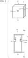
- FIG. 2 is a schematic configuration diagram showing an example of a water detecting device 3A according to the first embodiment.
- the water detecting system 1A functions as a system that detects a water generation situation present on a surface of an object installed in a surrounding environment, and notifies a user (an owner, a manager, a worker for inspection and repair or the like of the object) of a detection result.
- the object is any device or equipment through which water (tap water, sewage water, fresh water, seawater, industrial water, or the like) flows, with examples thereof including a pump device, piping, or the like used in an infrastructure facility (water supply, sewage disposal, or the like) or a plant facility (oil refining, power generation, manufacturing, chemical processes, or the like).
- a pump device used in an infrastructure facility (water supply, sewage disposal, or the like) or a plant facility (oil refining, power generation, manufacturing, chemical processes, or the like).
- a configuration of the water detecting system 1A includes the pump device 2 as an example of the object, the water detecting device 3A attached to the pump device 2, a management device 4A that manages an installation status and an operation status of the pump device 2, the detection result or the like by the water detecting device 3A, and a user terminal device 5 that is used by the user.
- Each of the devices 2 to 5 is configured as, for example, a general-purpose or dedicated computer (see FIG. 4 described later), and is configured to be able to transmit and receive various types of data to and from each other via a network 6.
- the water detecting system 1A includes one or a plurality of water detecting devices 3A, and one water detecting device 3A may be attached to one object, or a plurality of water detecting devices 3A may be attached to different locations on one object.
- the number of each of the devices 2 to 5 and the configuration of the network 6 are not limited to the example of FIG. 1 .
- the pump device 2 includes a pump unit 20, a motor 21 that serves as a drive source for the pump device 2, and a pump control panel 22 that controls an operation of the pump device 2.
- the pump unit 20 is constituted by, for example, an impeller, a rotary shaft, a bearing, a mechanical seal, a gland packing, a casing, piping or the like.
- the pump control panel 22 controls a rotational operation of the motor 21 and controls a communication operation when transmitting and receiving various types of information to and from the management device 4A, based on set values to which operating conditions are set by the user, and detection values of sensors (not shown) provided in each part of the pump unit 20 and the motor 21.
- the water detecting device 3A is disposed, for example, below the mechanical seal of the pump unit 20, and detects a generation situation of water present on a surface of the casing of the pump unit 20.
- the water detecting device 3A includes a housing 33, an object temperature and a humidity sensor 34 that detects a temperature and a humidity of the object (in the present embodiment, the pump device 2), and an environment temperature and a humidity sensor 35 that detects a temperature and a humidity of a surrounding environment in which the object (in the present embodiment, the pump device 2) is installed.
- the surrounding environment may be outdoors or may be indoors.
- the housing 33 internally stores the object temperature and humidity sensor 34 and the environment temperature and humidity sensor 35, and includes opening portions 330 and 331 formed in the object temperature and humidity sensor 34 and the environment temperature and humidity sensor 35, respectively.
- the housing 33 has, for example, a rectangular parallelepiped shape, and it is preferable that the opening portions 330 and 331 are formed on a surface having the largest area.
- the shape of the housing 33 and a position and a size of the opening portions 330 and 331 may be changed as appropriate.
- the object temperature and humidity sensor 34 is disposed on a side of the housing 33 facing the object, and for example, a water absorbing material 332 is disposed between the pump device 2 and the object temperature and humidity sensor 34.
- the environment temperature and humidity sensor 35 is disposed on a side of the housing 33 opposite to the object.
- the object temperature and humidity sensor 34 and the environment temperature and humidity sensor 35 are sensors capable of detecting a temperature and a humidity, and any detection method may be used.
- the object temperature and humidity sensor 34 and the environment temperature and humidity sensor 35 detect at least one or both of a relative humidity and an absolute humidity, and in a case where any one of the relative humidity and the absolute humidity is detected, the other of the relative humidity and the absolute humidity may be calculated based on one of the relative humidity and the absolute humidity and the temperature.
- a material and a shape of the water absorbing material 332 may be appropriately changed, and the water absorbing material 332 may be omitted according to an installation status of the water detecting device 3A and the like.
- the management device 4A is configured as, for example, a server type computer or a cloud type computer.
- the management device 4A collects various types of information from the pump device 2 and the water detecting device 3A and registers the collected information in a database.
- the management device 4A transmits notification information to the user terminal device 5, and when a request for information provision is received from the user terminal device 5, the management device 4A transmits the information registered in the database to the user terminal device 5 as provision information.
- the user terminal device 5 is configured as, for example, a stationary computer or a portable computer that is used by the user.
- the user terminal device 5 has a program installed, such as an application or a browser, receives various input operations, and outputs various types of information (notification information, provision information, and the like) via a display screen or audio output.
- the network 6 is configured using wired communication or wireless communication, or a combination of wired communication and wireless communication according to any communication standard.
- a communication network managed within a building such as a local network, or a combination of these communication networks.
- international standards are typically used as communication standards for wireless communication.
- methods such as IEEE802.15.4, IEEE802.15.1, IEEE802.15.11a, 11b, 11g, 11n, 11ac, 11ad, ISO/IEC14513-3-10, and IEEE802.15.4g exist.
- it is possible to use methods such as Bluetooth (registered trademark), Bluetooth Low Energy, Wi-Fi, ZigBee (registered trademark), Sub-GHz, EnOcean (registered trademark), and LTE.
- FIG. 3 is a block diagram showing an example of the water detecting device 3A according to the first embodiment.
- the water detecting device 3A includes, as main components thereof, a control unit 30, a communication unit 31, and a storage unit 32, in addition to the housing 33, the object temperature and humidity sensor 34, and the environment temperature and humidity sensor 35.
- the control unit 30 functions as an object temperature and humidity information acquisition unit 300, an environment temperature and humidity information acquisition unit 301, a determination unit 302A, and an output processing unit 303 by executing, for example, a water detection program 320A stored in the storage unit 32.
- the communication unit 31 is connected to the network 6 and functions as a communication interface that transmits and receives various data to and from, for example, the pump device 2, the management device 4A, or the user terminal device 5.
- the storage unit 32 stores various programs (the water detection program 320A and the like) and data (setting information 321 or the like) used in an operation of the water detecting device 3A.
- the setting information 321 stores parameters (various thresholds, cycles, and the like) referred to by the control unit 30 when the water detecting device 3A operates, and is configured to be set via, for example, the management device 4A or the user terminal device 5.
- the object temperature and humidity information acquisition unit 300 acquires object temperature and humidity information indicating changes over time in the temperature and humidity of the pump device 2 by receiving the temperature and humidity of the pump device 2 detected by the object temperature and humidity sensor 34 at a predetermined detection cycle.
- the environment temperature and humidity information acquisition unit 301 acquires environment temperature and humidity information indicating changes over time in the temperature and humidity of the surrounding environment by receiving the temperature and humidity of the surrounding environment detected by the environment temperature and humidity sensor 35 at a predetermined detection cycle.
- the determination unit 302A determines the presence or absence of water generation and a factor of water generation on the surface of the pump device 2 based on the object temperature and humidity information indicating the changes over time in the temperature and humidity of the pump device 2 detected by the object temperature and humidity sensor 34 and the environment temperature and humidity information indicating the changes over time in the temperature and humidity of the surrounding environment detected by the environment temperature and humidity sensor 35.
- the determination unit 302A performs a water determination process of determining the presence or absence of water generation on the surface of the pump device 2 based on the object temperature and humidity information, a condensation determination process of determining presence or absence of condensation water generation due to the surrounding environment based on the environment temperature and humidity information, and a water generation factor process of determining, when it is determined through the water determination process that water is generated on the surface of the pump device 2, whether the factor of water generation is condensation water caused by the pump device 2 or condensation water caused by the surrounding environment based on a determination result obtained by determining the presence or absence of condensation water generation through the condensation determination process. Specific contents of each process are described later.
- the output processing unit 303 outputs the determination results indicating the presence or absence of water generation and the factor of generation determined by the determination unit 302A.
- An output destination of the determination result may be the storage unit 32, or may be notified to the user by being output as notification information to the pump device 2, the management device 4A, or the user terminal device 5.
- FIG. 4 is a hardware configuration diagram showing an example of a computer 900 constituting each device.
- the computer 900 includes, as main components thereof, a bus 910, a processor 912, a memory 914, an input device 916, an output device 917, a display device 918, a storage device 920, a communication interface (I/F) unit 922, an external device I/F unit 924, an input/output (I/O) device I/F unit 926, and a medium input/output unit 928.
- the above-described components may be omitted as appropriate depending on the application for which the computer 900 is used.
- the processor 912 is configured as one or a plurality of arithmetic processing devices (CPU (central processing units), MPU (micro-processing units), DSP (digital signal processors), GPU (graphics processing unit), or the like) and operates as a control unit that oversees the entire computer 900.
- the memory 914 stores various data and a program 930, and is configured as, for example, a volatile memory (a DRAM, an SRAM, or the like) functioning as a main memory, a non-volatile memory (ROM), or a flash memory.
- the input device 916 is configured as, for example, a keyboard, a mouse, a numeric keypad, or an electronic pen, and functions as an input unit.
- the output device 917 is configured as, for example, an audio (voice) output device, or a vibration device, and functions as an output unit.
- the display device 918 is configured as, for example, a liquid crystal display, an organic EL display, an electronic paper, or a projector, and functions as an output unit.
- the input device 916 and the display device 918 may be integrated into one device, such as a touch panel display.
- the storage device 920 is configured as, for example, an HDD, or an SSD, and functions as a storage unit.
- the storage device 920 stores various data required for executing an operating system or the program 930.
- the communication I/F unit 922 is connected to a network 940 (which may be the same as the network 6 in FIG. 1 ) such as the internet or an intranet in a wired or wireless manner, and functions as a communication unit that transmits and receives data to and from another computer according to a predetermined communication standard.
- the external device I/F unit 924 is connected to an external device 950 such as a camera, a printer, a scanner, or a reader/writer in a wired or wireless manner, and functions as a communication unit that transmits and receives data to and from the external device 950 according to a predetermined communication standard.
- the I/O device I/F unit 926 is connected to an I/O device 960 such as various sensors and actuators, and functions as a communication unit that transmits and receives various signals and data, such as a detection signal from a sensor and a control signal for an actuator, to and from the I/O device 960.
- the medium input/output unit 928 is configured as, for example, a drive device such as a DVD (digital versatile disc) drive or a CD (compact disc) drive, a memory card slot, or a USB connector, and reads and writes data from and to a medium (non-transitory storage medium) 970 such as a DVD, a CD, a memory card, and a USB memory.
- the processor 912 loads the program 930 stored in the storage device 920 into the memory 914, executes the program 930, and controls each unit of the computer 900 via the bus 910.
- the program 930 may be stored in the memory 914 instead of the storage device 920.
- the program 930 may be recorded on the medium 970 in an installable file format or an executable file format and may be provided to the computer 900 via the medium input/output unit 928.
- the program 930 may be provided to the computer 900 by being downloaded via the communication I/F unit 922 through the network 940.
- the computer 900 may implement various functions that are implemented by the processor 912 executing the program 930 using hardware such as an FPGA (field-programmable gate array) or an ASIC (application specific integrated circuit).
- the computer 900 is configured as a stationary computer or a portable computer, and is any form of electronic device.
- the computer 900 may be a client type computer, a server type computer, or may be a cloud type computer.
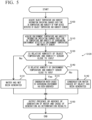
- FIG. 5 is a flowchart showing an example of the operation of the water detecting device 3A according to the first embodiment.
- FIG. 6 is a graph showing an example of changes over time in the object temperature and humidity sensor 34 and the environment temperature and humidity sensor 35.
- a series of processes shown in FIG. 5 may be repeatedly executed at, for example, a predetermined execution cycle, or may be executed based on an execution command from the pump device 2, the management device 4A, or the user terminal device 5.
- step S100 the object temperature and humidity information acquisition unit 300 of the water detecting device 3A acquires the object temperature and humidity information indicating the changes over time in the temperature and humidity of the pump device 2, by receiving the temperature and humidity of the pump device 2 detected by the object temperature and humidity sensor 34 at a predetermined detection cycle.
- step S110 the environment temperature and humidity information acquisition unit 301 acquires the environment temperature and humidity information indicating the changes over time in the temperature and humidity of the surrounding environment by receiving the temperature and humidity of the surrounding environment detected by the environment temperature and humidity sensor 35, at a predetermined detection cycle.
- step S120 (specifically, steps S130 to S142), the determination unit 302A determines the presence or absence of water generation and the factor of water generation on the surface of the pump device 2 based on the object temperature and humidity information acquired in step S100 and the environment temperature and humidity information acquired in step S110.
- the determination unit 302A performs the water determination process of determining the presence or absence of water generation on the surface of the pump device 2 based on the object temperature and humidity information. Specifically, it is determined whether or not a relative humidity of the pump device 2 based on the object temperature and humidity information is close to 100%, and in a case where the relative humidity is close to 100%, it is determined that water is generated. In this case, in a case where the relative humidity of the pump device 2 exceeds a predetermined threshold (for example, 95%), it is considered that the relative humidity is close to 100%, and it may be determined that water is generated.
- a predetermined threshold for example, 95%)
- a duration time during which the relative humidity of the pump device 2 exceeds a predetermined threshold (for example, 90%) exceeds a predetermined time threshold, it is considered that the relative humidity is close to 100%, and it may be determined that water is generated.
- the determination unit 302A determines through the water determination process in step S130 that water is generated (that is, when "Yes" is determined in step S 130)
- the determination unit 302A performs the condensation determination process of determining the presence or absence of condensation water generation due to the surrounding environment based on the environment temperature and humidity information in step S140. Specifically, it is determined whether or not a relative humidity of the surrounding environment based on the environment temperature and humidity information is close to 100%, and in a case where the relative humidity is close to 100%, it is determined that condensation water is generated. In this case, in a case where the relative humidity of the surrounding environment exceeds a predetermined threshold (for example, 95%), it is considered that the relative humidity is close to 100%, and it may be determined that condensation water is generated.
- a predetermined threshold for example, 95%)
- the determination unit 302A performs the water generation factor process based on a determination result in step S140. That is, when it is determined through the condensation determination process in step S140 that condensation water due to the surrounding environment is generated (that is, when "Yes” is determined in step S140), it is considered that the situation is as shown in (a) of FIG. 6 , and it is determined in step S141 that the factor of water generation on the surface of the pump device 2 is condensation water caused by the surrounding environment. On the other hand, when the determination unit 302A determines through the condensation determination process in step S140 that condensation water due to the surrounding environment is not generated (that is, when "No” is determined in step S140), it is considered that the situation is as shown in (b) of FIG. 6 , and it is determined in step S142 that the factor of water generation on the surface of the pump device 2 is condensation water caused by the pump device 2.
- the determination unit 302A determines through the water determination process in step S130 that water is not generated (that is, when "No" is determined in step S130), the determination unit 302A determines in step S131 that water is not generated.
- step S150 the output processing unit 303 outputs a determination result (specifically, determination results of steps S131, S141, and S142) by the determination unit 302A in step S120, and the series of processes is ended.
- step S100 corresponds to an object temperature and humidity information acquisition step
- step S110 corresponds to an environment temperature and humidity information acquisition step
- step S120 corresponds to a determination step
- step S150 corresponds to an output processing step.
- the water detecting device 3A it is possible to determine the presence or absence of generation and the factor of water generation on the surface of the object (pump device 2) by combining the object temperature and humidity information indicating the changes over time in the temperature and humidity of the pump device 2 with the environment temperature and humidity information indicating the changes over time in the temperature and humidity of the surrounding environment.
- FIG. 7 is an overall configuration diagram showing an example of a water detecting system 1B according to a second embodiment.
- FIG. 8 is a block diagram showing an example of an object monitoring device 7A and a management device 4B according to the second embodiment.
- the water detecting system 1B is different from the first embodiment in that the water detecting system 1B includes the object monitoring device 7A attached to the pump device 2 instead of the water detecting device 3A, and the management device 4B implements functions of the water detecting method performed by the control unit 30 of the water detecting device 3A.
- a basic configuration and operation are common to the first embodiment.
- the water detecting system 1B includes one or a plurality of object monitoring devices 7A, and one object monitoring device 7A may be attached to one object, or a plurality of object monitoring devices 7A may be attached to different locations of one object.
- feature parts of the present embodiment are mainly described.
- the object monitoring device 7A is a device in which the object temperature and humidity information acquisition unit 300, the environment temperature and humidity information acquisition unit 301, the determination unit 302A, and the output processing unit 303 are omitted from the water detecting device 3A according to the first embodiment. That is, the object monitoring device 7A includes a control unit 70, a communication unit 71, a storage unit 72, a housing 73, an object temperature and humidity sensor 74, and an environment temperature and humidity sensor 75.
- the control unit 70, the communication unit 71, and the storage unit 72 may be omitted as appropriate.
- the object temperature and humidity sensor 74 and the environment temperature and humidity sensor 75 may be connected to, for example, the pump control panel 22 of the pump device 2.
- the object temperature and humidity sensor 74 and the environment temperature and humidity sensor 75 transmit sensor data to the management device 4B at a predetermined transmission cycle through the control unit 70 and the communication unit 71.
- the transmission cycle of the sensor data may be the same as the detection cycle of the object temperature and humidity sensor 74 and the environment temperature and humidity sensor 75.
- the transmission cycle of the sensor data may be longer than the detection cycle of the object temperature and humidity sensor 74 and the environment temperature and humidity sensor 75. In that case, the object temperature and humidity sensor 74 and the environment temperature and humidity sensor 75 may collectively transmit the sensor data accumulated during the transmission cycle.
- the management device 4B includes, as main components thereof, a control unit 40, a communication unit 41, and a storage unit 42.
- the control unit 40 functions as an object temperature and humidity information acquisition unit 400, an environment temperature and humidity information acquisition unit 401, a determination unit 402A, and an output processing unit 403 by executing, for example, a water detection program 420A stored in the storage unit 42. Since the object temperature and humidity information acquisition unit 400, the environment temperature and humidity information acquisition unit 401, the determination unit 402A, and the output processing unit 403 function in the same manner as the object temperature and humidity information acquisition unit 300, the environment temperature and humidity information acquisition unit 301, the determination unit 302A, and the output processing unit 303 according to the first embodiment, detailed descriptions thereof are omitted.
- the management device 4B it is possible to determine the presence or absence of water generation and the factor of water generation on the surface of the object (pump device 2), by combining the object temperature and humidity information indicating the changes over time in the temperature and humidity of the pump device 2 with the environment temperature and humidity information indicating the changes over time in the temperature and humidity of the surrounding environment.
- FIG. 9 is an overall configuration diagram showing an example of a water detecting system 1C according to a third embodiment.
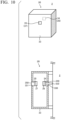
- FIG. 10 is a schematic configuration diagram showing an example of a water detecting device 3B according to the third embodiment.
- the water detecting system 1C according to the present embodiment is different from the first embodiment in that the water detecting device 3B further includes an object temperature and humidity sensor heater 36 disposed close to the object temperature and humidity sensor 34 and an environment temperature and humidity sensor heater 37 disposed close to the environment temperature and humidity sensor 35.
- a basic configuration and operation are common to the first embodiment.
- feature parts of the present embodiment are mainly described.
- the object temperature and humidity sensor heater 36 is disposed to be able to heat at least one of a sensing portion 340 of the object temperature and humidity sensor 34 and the surface of the pump device 2 as the object.
- the environment temperature and humidity sensor heater 37 is disposed to be able to heat a sensing portion 350 of the environment temperature and humidity sensor 35.
- the object temperature and humidity sensor heater 36 and the environment temperature and humidity sensor heater 37 are disposed on back sides of the sensing portions 340 and 350, respectively, and heat the sensing portions 340 and 350 in a planar manner.
- the object temperature and humidity sensor heater 36 and the environment temperature and humidity sensor heater 37 are switched between and ON and OFF operations of a heating state based on, for example, a timer circuit or heating control by the control unit 30.
- the object temperature and humidity sensor heater 36 and the environment temperature and humidity sensor heater 37 repeatedly perform the ON and OFF operations of being turned ON for a predetermined ON period (for example, 20 seconds) by being switched from OFF to ON and then being turned OFF for a predetermined OFF period (for example, 380 seconds) by being switched from ON to OFF, at a predetermined time interval (for example, at an interval of 400 seconds).
- the ON and OFF operations of the object temperature and humidity sensor heater 36 and the environment temperature and humidity sensor heater 37 may be performed synchronously or asynchronously.
- FIG. 11 is a block diagram showing an example of the water detecting device 3B according to the third embodiment.
- the water detecting device 3B includes, as main components thereof, in addition to the housing 33, the object temperature and humidity sensor 34, the environment temperature and humidity sensor 35, the object temperature and humidity sensor heater 36, and the environment temperature and humidity sensor heater 37, the control unit 30, the communication unit 31, and the storage unit 32, similarly to the water detecting device 3A according to the first embodiment.
- the control unit 30 functions as the object temperature and humidity information acquisition unit 300, the environment temperature and humidity information acquisition unit 301, a heater information acquisition unit 304, a determination unit 302B, and the output processing unit 303 by executing, for example, a water detection program 320B stored in the storage unit 32. Since the object temperature and humidity information acquisition unit 300, the environment temperature and humidity information acquisition unit 301, and the output processing unit 303 function in the same manner as the object temperature and humidity information acquisition unit 300, the environment temperature and humidity information acquisition unit 301, and the output processing unit 303 according to the first embodiment, detailed descriptions thereof are omitted.
- the heater information acquisition unit 304 acquires heater information indicating changes over time in heating states of the object temperature and humidity sensor heater 36 and the environment temperature and humidity sensor heater 37.
- the heater information includes a time at which the ON and OFF operations of the object temperature and humidity sensor heater 36 and the environment temperature and humidity sensor heater 37 are switched.
- the heater information is acquired by a timer circuit, operation command data by the control unit 30, and a detection value of a current sensor provided in the object temperature and humidity sensor heater 36 and the environment temperature and humidity sensor heater 37.
- the determination unit 302B determines the presence or absence of water generation and the factor of water generation on the surface of the pump device 2 based on the object temperature and humidity information indicating the changes over time in the temperature and humidity of the pump device 2 detected by the object temperature and humidity sensor 34, the environment temperature and humidity information indicating the changes over time in the temperature and humidity of the surrounding environment detected by the environment temperature and humidity sensor 35, and the heater information indicating the changes over time in the heating states of the object temperature and humidity sensor heater 36 and the environment temperature and humidity sensor heater 37.
- the determination unit 302B performs a water determination process of determining the presence or absence of water generation on the surface of the pump device 2 based on the object temperature and humidity information and the heater information, a first condensation determination process of determining presence or absence of condensation water generation due to the pump device 2 based on the object temperature and humidity information, the environment temperature and humidity information, and the heater information, a second condensation determination process of determining presence or absence of condensation water generation due to the surrounding environment based on the object temperature and humidity information, the environment temperature and humidity information, and the heater information, and a water generation factor process of determining, when it is determined through the water determination process that water is generated on the surface of the pump device 2, whether the factor of water generation is water leakage caused by the pump device 2, condensation water caused by the pump device 2, or condensation water caused by the surrounding environment based on a determination result obtained by determining the presence or absence of condensation water generation through the first condensation determination process, and a determination result obtained by determining the presence or absence of condensation water generation through the second condensation determination process.
- the determination unit 302B calculates a dew point of the surrounding environment from the temperature and humidity of the surrounding environment indicated by the environment temperature and humidity information, and uses the calculated dew point in each of first and second condensation determination processes. Specific contents of each process are described later.
- FIGS. 12 and 13 are flowcharts showing an example of the operation of the water detecting device 3B according to the third embodiment.
- a series of processes shown in FIGS. 12 and 13 may be repeatedly executed at, for example, a predetermined execution cycle, or may be executed based on an execution command from the pump device 2, the management device 4C, or the user terminal device 5.
- step S200 the object temperature and humidity information acquisition unit 300 of the water detecting device 3B acquires the object temperature and humidity information from the object temperature and humidity sensor 34. Then, in step S210, the environment temperature and humidity information acquisition unit 301 acquires the environment temperature and humidity information from the environment temperature and humidity sensor 35. Next, in step S220, the heater information acquisition unit 304 acquires the heater information from the object temperature and humidity sensor heater 36 and the environment temperature and humidity sensor heater 37.
- step S230 the determination unit 302B determines the presence or absence of water generation and the factor of water generation on the surface of the pump device 2 based on the object temperature and humidity information acquired in step S200, the environment temperature and humidity information acquired in step S210, and the heater information acquired in step S220.
- step S240 the determination unit 302B performs the water determination process of determining the presence or absence of water generation on the surface of the pump device 2 based on the object temperature and humidity information and the heater information.
- first to third water determination processes performed by the determination unit 302B are described.
- the determination unit 302B may execute at least one of the first to third water determination processes, or may execute all of the first to third water determination processes.
- FIG. 14 is a flowchart showing an example of the first water determination process (step S240) by the water detecting device 3B according to the third embodiment.
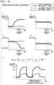
- FIG. 15 is a graph showing an example of changes over time in the object temperature and humidity sensor 34 depending on the presence or absence of water generation.
- it is determined whether or not water present on the surface of the pump device 2 mainly moves toward an object temperature and humidity sensor 34 side via the water absorbing material 332 and comes into contact with the sensing portion 340.
- step S300 the determination unit 302B determines whether or not the relative humidity of the pump device 2 based on the object temperature and humidity information is greater than or equal to a predetermined threshold (for example, 80%) during the on period of the object temperature and humidity sensor heater 36. Then, when it is determined in step S300 that the relative humidity of the pump device 2 is greater than or equal to the predetermined threshold (that is, when "Yes" is determined in step S300), it is determined in step S310 whether or not the absolute humidity of the pump device 2 based on the object temperature and humidity information shows an increasing tendency in the ON period of the object temperature and humidity sensor heater 36.
- a predetermined threshold for example, 80%
- step S310 when it is determined in step S310 that the absolute humidity of the pump device 2 shows an increasing tendency (that is, when "Yes” is determined in step S310), it is considered that the situation is as shown in (b) of FIG. 15 , and it is determined in step S320 that water is generated.
- steps S300 and S310 that water is not generated (that is, when "No” is determined in step S300 or "No” is determined in step S310)
- it is considered that the situation is as shown in (a) of FIG. 15 , and it is determined in step S321 that water is not generated.
- FIG. 16 is a flowchart showing an example of the second water determination process (step S240) by the water detecting device 3B according to the third embodiment.
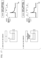
- FIG. 17 is a graph showing an example of changes over time in the object temperature and humidity sensor 34 depending on the presence or absence of water generation.
- the second water determination process as shown in FIG. 17 , the presence or absence of water that is present on the surface of the pump device 2 before moving toward the object temperature and humidity sensor 34 side via the water absorbing material 332, that is, water that is not in contact with the sensing portion 340 and is present on the surface of the pump unit 20 is determined.
- step S400 the determination unit 302B determines whether or not the absolute humidity of the pump device 2 based on the object temperature and humidity information shows an increasing tendency or a maintained tendency during the ON period of the object temperature and humidity sensor heater 36. Then, in a case where it is determined in step S400 that the absolute humidity of the pump device 2 shows an increasing tendency or a maintained tendency (that is, when "Yes" is determined in step S400), it is considered that the situation is as shown in (b) of FIG. 17 , and it is determined in step S410 that water is generated.
- step S400 when it is determined in step S400 that the absolute humidity of the pump device 2 does not show an increasing tendency or a maintained tendency (that is, when "No" is determined in step S400), it is considered that the situation is as shown in (a) of FIG. 17 , and it is determined in step S411 that water is not generated.
- the determination unit 302B determines whether or not the relative humidity of the pump device 2 based on the object temperature and humidity information is close to 100% in the same manner as in step S130 of FIG. 5 , and determines that water is generated in a case where the relative humidity is close to 100%. In this case, in a case where the relative humidity of the pump device 2 exceeds a predetermined threshold (for example, 95%), it may be determined that water is generated. In a case where a duration time during which the relative humidity of the pump device 2 exceeds a predetermined threshold (for example, 90%) exceeds a predetermined time threshold, it is considered that the relative humidity of the pump device 2 is close to 100%, and it may be determined that water is generated.
- a predetermined threshold for example, 97%
- the determination unit 302B determines through the water determination process in step S240 that water is generated (that is, when "Yes" is determined in step S240)
- the determination unit 302B performs the first condensation determination process of determining the presence or absence of condensation water generation due to the pump device 2 based on the object temperature and humidity information, the environment temperature and humidity information, and the heater information in steps S250 to S252.
- FIG. 18 is a graph showing an example of changes over time in the object temperature and humidity sensor 34 and the environment temperature and humidity sensor 35 when condensation water due to the object is generated.
- the first condensation determination process it is determined that condensation water due to the pump device 2 is generated by detecting the situation shown in FIG. 18 .
- step S250 the determination unit 302B determines whether or not only the temperature of the pump device 2 based on the object temperature and humidity information has gradually decreased and reaches the dew point of the surrounding environment based on the environment temperature and humidity information. That is, in step S250, it is determined whether or not the situation is as shown in (c) of FIG. 18 .
- the dew point of the surrounding environment may be calculated from, for example, the temperature and the relative humidity detected by the environment temperature and humidity sensor 35, or may be calculated from the absolute humidity detected by the environment temperature and humidity sensor 35.
- step S251 the determination unit 302B determines, when the ON and OFF operations of the object temperature and humidity sensor heater 36 and the environment temperature and humidity sensor heater 37 are repeatedly performed, whether or not the relative humidity of the pump device 2 based on the object temperature and humidity information is less than or equal to a predetermined lower limit threshold (for example, 5%) for a predetermined number of repetitions (for example, six times) in the ON period of the object temperature and humidity sensor heater 36.
- a predetermined lower limit threshold for example, 5%
- a predetermined number of repetitions for example, six times
- step S251 when it is determined in step S251 that a relative humidity of the object temperature and humidity sensor 34 is less than or equal to the predetermined lower limit threshold (that is, when "Yes" is determined in step S251), the determination unit 302B determines in step S252 whether or not the relative humidity of the pump device 2 based on the object temperature and humidity information shows an increasing tendency for a predetermined number of repetitions (for example, six times) in a comparison of a plurality of ON periods of the object temperature and humidity sensor heater 36. That is, in steps S251 and S252, it is determined whether or not the situation is shown in (e) of FIG. 18 .
- both the relative humidities of the object temperature and humidity sensor 34 and a relative humidity of the environment temperature and humidity sensor 35 decrease to the lower limit threshold (for example, 5%) or lower, and there is no difference in the change.
- the relative humidity of the environment temperature and humidity sensor 35 decreases to the lower limit threshold.
- the relative humidity of the object temperature and humidity sensor 34 does not decrease to the lower limit threshold but remains at a relative humidity as high as about an upper limit threshold (for example, 80%) when the plurality of ON periods are compared. In steps S251 and S252, such behavior may be detected, and a determination method other than the above may be used.
- the determination unit 302B performs the water generation factor process based on determination results of steps S250 to S252. That is, when it is determined through the first condensation determination process of steps S250 to S252 that condensation water due to the pump device 2 is generated (that is, in a case where "Yes" is determined in all of steps S250 to S252), it is determined in step S253 that the factor of water generation on the surface of the pump device 2 is condensation water caused by the pump device 2.
- the determination unit 302B determines through the first condensation determination process of steps S250 to S252 that condensation water due to the pump device 2 is not generated (that is, when "No" is determined in any of steps S250 to S252)
- the determination unit 302B performs the second condensation determination process of determining the presence or absence of condensation water generation due to the surrounding environment based on the object temperature and humidity information, the environment temperature and humidity information, and the heater information in steps S260 and S261.
- FIG. 19 is a graph showing an example of changes over time in the object temperature and humidity sensor 34 and the environment temperature and humidity sensor 35 when condensation water due to the surrounding environment is generated. In the second condensation determination process, it is determined that condensation water due to the surrounding environment is generated, by detecting the situation shown in FIG. 19 .
- step S260 the determination unit 302B determines whether or not the temperature of the pump device 2 based on the object temperature and humidity information and the temperature of the surrounding environment based on the environment temperature and humidity information have gradually decreased and reached the dew point of the surrounding environment based on the environment temperature and humidity information. That is, in step S260, it is determined whether or not the situation is as shown in (c) of FIG. 19 .
- the dew point of the surrounding environment may be calculated from, for example, the temperature and the relative humidity detected by the environment temperature and humidity sensor 35, or may be calculated from the absolute humidity detected by the environment temperature and humidity sensor 35.
- step S261 the determination unit 302B determines, when the ON and OFF operations of the object temperature and humidity sensor heater 36 and the environment temperature and humidity sensor heater 37 are repeatedly performed, whether or not the relative humidity of the surrounding environment based on the environment temperature and humidity information is greater than or equal to a predetermined upper limit threshold (for example, 95%) in the OFF period of the object temperature and humidity sensor heater 36. That is, in step S261, it is determined whether or not the situation is as shown in (e) of FIG. 19 .
- a predetermined upper limit threshold for example, 95%
- step S261 such behavior may be detected, and a determination method other than the above may be used.
- the determination unit 302B performs the water generation factor process based on determination results in steps S260 and S261. That is, when it is determined through the second condensation determination process in steps S260 and S261 that condensation water due to the surrounding environment is generated (that is, when "Yes" is determined in both steps S260 and S261), it is determined in step S262 that the factor of water generation on the surface of the pump device 2 is condensation water caused by the surrounding environment.
- the determination unit 302B determines through the second condensation determination process in steps S260 and S261 that condensation water due to the surrounding environment is not generated (that is, when "No" is determined in any of steps S260 and S261)
- the determination unit 302B determines in step S270 that the factor of water generation on the surface of the pump device 2 is water leakage caused by the pump device 2.
- FIG. 20 is a graph showing an example of changes over time in the object temperature and humidity sensor 34 and the environment temperature and humidity sensor 35 when water leakage due to the object has occurred.
- the determination unit 302B determines through the water determination process that water is generated (when "Yes” is determined in step S240) and determines through the first and second condensation determination processes that the cause of water generation is not condensation water (that is, when "No” is determined in any of steps S250 to S252 and “No” is determined in any of steps S260 and S261), it is determined that the cause of water generation is water leakage caused by the pump device 2.
- the determination unit 302B may further perform a water leakage determination process of determining the presence or absence of occurrence of water leakage due to the object based on the object temperature and humidity information, the environment temperature and humidity information, and the heater information.
- the determination unit 302B determines, when the ON and OFF operations of the object temperature and humidity sensor heater 36 and the environment temperature and humidity sensor heater 37 are repeatedly performed, whether or not the relative humidity of the pump device 2 based on the object temperature and humidity information is greater than or equal to a predetermined first threshold (for example, 80%) in the ON period of the object temperature and humidity sensor heater 36, and whether or not the relative humidity of the surrounding environment based on the environment temperature and humidity information is less than or equal to a second threshold (for example, 5%) set to be lower than the first threshold in the ON period of the environment temperature and humidity sensor heater 37.
- a predetermined first threshold for example, 80%
- a second threshold for example, 5%
- the determination unit 302B determines that water leakage due to the object has occurred.
- the water leakage determination process behavior as shown in FIG. 20 may be detected, and a determination method other than the above may be used.
- step S240 when it is determined through the water determination process in step S240 that water is not generated (that is, when "No" is determined in step S240), the determination unit 302B determines that water is not generated in step S241.
- step S280 the output processing unit 303 outputs a determination result (specifically, determination results of steps S241, S253, S262, and S270) by the determination unit 302B in step S230, and the series of processes is ended.
- step S200 corresponds to the object temperature and humidity information acquisition step
- step S210 corresponds to the environment temperature and humidity information acquisition step
- step S220 corresponds to a heater information acquisition step
- step S230 corresponds to the determination step
- step S280 corresponds to the output processing step.
- the water detecting device 3B it is possible to determine the presence or absence of water generation and the factor of water generation on the surface of the object (pump device 2) by combining the object temperature and humidity information indicating the changes over time in the temperature and humidity of the pump device 2, the environment temperature and humidity information indicating the changes over time in the temperature and humidity of the surrounding environment, and the heater information indicating the changes over time in the heating states of the object temperature and humidity sensor heater 36 and the environment temperature and humidity sensor heater 37.
- the determination unit 302B determines whether water is generated on the surface of the object, the determination unit 302B can determine whether the factor of water generation is condensation water or water leakage. Therefore, it is possible to appropriately detect, for example, mechanical leakage due to damage or aging deterioration of the object without using an expensive water leakage sensor such as an electrode type or infrared type water leakage sensor.
- the water detecting system 1D according to the present embodiment is different from the third embodiment in that the water detecting system 1D includes the object monitoring device 7B attached to the pump device 2 instead of the water detecting device 3B, and the management device 4D implements functions of the water detecting method performed by the control unit 30 of the water detecting device 3B.
- a basic configuration and operation are common to the third embodiment.
- feature parts of the present embodiment are mainly described.
- the management device 4D it is possible to determine the presence or absence of water generation and the factor of water generation on the surface of the object (pump device 2) by combining the object temperature and humidity information indicating the changes over time in the temperature and humidity of the pump device 2, the environment temperature and humidity information indicating the changes over time in the temperature and humidity of the surrounding environment, and the heater information indicating the changes over time in the heating states of the object temperature and humidity sensor heater 76 and the environment temperature and humidity sensor heater 77.
- the determination unit 402B determines whether water is generated on the surface of the object, the determination unit 402B can determine whether the factor of water generation is condensation water or water leakage. Therefore, it is possible to appropriately detect, for example, mechanical leakage due to damage or aging deterioration of the object without using an expensive water leakage sensor such as an electrode type or infrared type water leakage sensor.
- the water detecting devices 3A and 3B are implemented by the device including the control unit 30, the communication unit 31, and the storage unit 32
- some or all of the functions (particularly, the function of the control unit 30) of the water detecting devices 3A and 3B may be implemented by the pump control panel 22 of the pump device 2 or the user terminal device 5.
- the functions may be implemented by a remote device such as a server type, a cloud type, or a central monitoring center type device.
- the object temperature and humidity sensor 34 and the environment temperature and humidity sensor 35 may be connected to the pump control panel 22, the user terminal device 5, or the remote device by wire or wirelessly to transmit and receive various data.
- the object monitoring devices 7A and 7B are implemented by the device including the control unit 70, the communication unit 71, and the storage unit 72 is described, but some or all of the functions (particularly, the function of the control unit 70) of the object monitoring devices 7A and 7B may be implemented by the pump control panel 22 of the pump device 2 or the user terminal device 5.
- the functions may be implemented by a remote device such as a server type, a cloud type, or a central monitoring center type device.
- the object temperature and humidity sensor 34 and the environment temperature and humidity sensor 35 may be connected to the pump control panel 22, the user terminal device 5, or the remote device by wire or wirelessly to transmit and receive various data.
- the water detecting systems 1A to 1D may include a remote device such as a server type, a cloud type, or a central monitoring center type device instead of or in addition to the user terminal device 5.
- the remote device may operate in the same manner as the user terminal device 5 according to the above-described embodiments, and may further transmit and receive various data to and from a client type device that may be connected to the remote device.
- the water detecting device 3A and the management device 4B have been described as executing the water detecting method of determining the presence or absence of water generation and the cause of water generation based on the object temperature and humidity information and the environment temperature and humidity information, the water detecting method may be executed using a learning model based on machine learning.
- the water detecting device 3B and the management device 4D according to the above-described embodiment have been described as executing the water detecting method of determining the presence or absence of water generation and the cause of water generation based on the object temperature and humidity information, the environment temperature and humidity information, and the heater information
- the water detecting method may be executed using a learning model based on machine learning.
- the learning model is obtained by training a correlation between input data and output data through machine learning, for example, by using the object temperature and humidity information and the environment temperature and humidity information, or the object temperature and humidity information, the environment temperature and humidity information, and the heater information as the input data, and using the presence or absence of water generation and the cause of generation as the output data.
- the machine learning mentioned here is a method called supervised learning, and any machine learning method such as a neural network (including deep learning), a decision tree, ensemble learning, clustering, multivariate analysis, or a support vector machine may be adopted.
Landscapes
- Physics & Mathematics (AREA)
- General Physics & Mathematics (AREA)
- Biochemistry (AREA)
- General Health & Medical Sciences (AREA)
- Health & Medical Sciences (AREA)
- Life Sciences & Earth Sciences (AREA)
- Chemical & Material Sciences (AREA)
- Analytical Chemistry (AREA)
- Business, Economics & Management (AREA)
- Emergency Management (AREA)
- Immunology (AREA)
- Pathology (AREA)
- Investigating Or Analyzing Materials Using Thermal Means (AREA)
- Emergency Alarm Devices (AREA)
- Testing And Monitoring For Control Systems (AREA)
- Examining Or Testing Airtightness (AREA)
- Testing Or Calibration Of Command Recording Devices (AREA)
Abstract
Description
- The present invention relates to a water detecting device, a water detecting system, and a water detecting method.
- Priority is claimed on
Japanese Patent Application No. 2022-102903, filed June 27, 2022 - Conventionally, by providing a temperature and humidity sensor in a device, whether or not water is generated due to condensation is determined based on a temperature and a humidity detected by the temperature and humidity sensor (for example, see
Patent Documents 1 and 2). -
- Patent Document 1:
Japanese Unexamined Patent Application, First Publication No. 2015-017853 - Patent Document 2:
Japanese Unexamined Patent Application, First Publication No. 2015-059691 - In devices described in
Patent Documents - In view of the above-described problems, an object of the present invention is to provide a water detecting device, a water detecting system, and a water detecting method capable of detecting not only the presence or absence of water generation, but also a cause of water generation.
- In order to achieve the above object, according to an aspect of the present invention, a water detecting device that detects a water generation situation present on a surface of an object, installed in a surrounding environment and through which water flows, the device includes: an object temperature and humidity sensor that detects a temperature and a humidity of the object, an environment temperature and humidity sensor that detects a temperature and a humidity of the surrounding environment, and a determination unit that determines presence or absence of water generation and a factor of water generation based on object temperature and humidity information indicating changes over time in the temperature and humidity detected by the object temperature and humidity sensor, and environment temperature and humidity information indicating changes over time in the temperature and humidity detected by the environment temperature and humidity sensor.
- With the water detecting device according to the present invention, the water detecting device includes the object temperature and humidity sensor, the environment temperature and humidity sensor, and the determination unit, and the determination unit determines the presence or absence of water generation and the factor of water generation based on the object temperature and humidity information indicating the changes over time in the temperature and humidity detected by the object temperature and humidity sensor and the environment temperature and humidity information indicating the changes over time in the temperature and humidity detected by the environment temperature and humidity sensor. As a result, not only is it possible to detect the presence or absence of water generation but also the cause of water generation.
- Problems, configurations, and effects other than those above described are made clear embodiments for implementing the invention, which are described later on.
-
- [
FIG. 1 ] An overall configuration diagram showing an example of a water detecting system according to a first embodiment. - [
FIG. 2 ] A schematic configuration diagram showing an example of a water detecting device according to the first embodiment. - [
FIG. 3 ] A block diagram showing an example of the water detecting device according to the first embodiment. - [
FIG. 4 ] A hardware configuration diagram showing an example of a computer constituting each device. - [
FIG. 5 ] A flowchart showing an example of an operation of the water detecting device according to the first embodiment. - [
FIG. 6 ] A graph showing an example of changes over time in an object temperature and humidity sensor and an environment temperature and humidity sensor. - [
FIG. 7 ] An overall configuration diagram showing an example of a water detecting system according to a second embodiment. - [
FIG. 8 ] A block diagram showing an example of an object monitoring device and a management device according to the second embodiment. - [
FIG. 9 ] An overall configuration diagram showing an example of a water detecting system according to a third embodiment. - [
FIG. 10 ] A schematic configuration diagram showing an example of a water detecting device according to the third embodiment. - [
FIG. 11 ] A block diagram showing an example of the water detecting device according to the third embodiment. - [
FIG. 12 ] A flowchart showing an example of an operation of the water detecting device according to the third embodiment. - [
FIG. 13 ] A flowchart showing an example of the operation of the water detecting device according to the third embodiment (continuation ofFIG. 12 ). - [
FIG. 14 ] A flowchart showing an example of a first water determination process by the water detecting device according to the third embodiment. - [
FIG. 15 ] A graph showing an example of changes over time in the object temperature and humidity sensor depending on presence or absence of water generation. - [
FIG. 16 ] A flowchart showing an example of a second water determination process by the water detecting device according to the third embodiment. - [
FIG. 17 ] A graph showing an example of changes over time in the object temperature and humidity sensor depending on the presence or absence of water generation. - [
FIG. 18 ] A graph showing an example of changes over time in the object temperature and humidity sensor and the environment temperature and humidity sensor when condensation water due to an object is generated. - [
FIG. 19 ] A graph showing an example of changes over time in the object temperature and humidity sensor and the environment temperature and humidity sensor when condensation water due to a surrounding environment is generated. - [
FIG. 20 ] A graph showing an example of changes over time in the object temperature and humidity sensor and the environment temperature and humidity sensor when water leakage due to the object has occurred. - [
FIG. 21 ] An overall configuration diagram showing an example of a water detecting system according to a fourth embodiment. - [
FIG. 22 ] A block diagram showing an example of an object monitoring device and a management device according to the fourth embodiment. - Hereinafter, embodiments of the present invention are described with reference to the drawings. Hereinafter, a scope required to achieve an object of the present invention is schematically shown, and required explanations of the required scope are mainly described herein.
-
FIG. 1 is an overall configuration diagram showing an example of a water detecting system 1A according to a first embodiment.FIG. 2 is a schematic configuration diagram showing an example of awater detecting device 3A according to the first embodiment. - The water detecting system 1A functions as a system that detects a water generation situation present on a surface of an object installed in a surrounding environment, and notifies a user (an owner, a manager, a worker for inspection and repair or the like of the object) of a detection result.
- The object is any device or equipment through which water (tap water, sewage water, fresh water, seawater, industrial water, or the like) flows, with examples thereof including a pump device, piping, or the like used in an infrastructure facility (water supply, sewage disposal, or the like) or a plant facility (oil refining, power generation, manufacturing, chemical processes, or the like). In the present embodiment, explanation centers around a case where the object is a
pump device 2 that transfers water. - Specifically, a configuration of the water detecting system 1A includes the
pump device 2 as an example of the object, thewater detecting device 3A attached to thepump device 2, amanagement device 4A that manages an installation status and an operation status of thepump device 2, the detection result or the like by thewater detecting device 3A, and auser terminal device 5 that is used by the user. Each of thedevices 2 to 5 is configured as, for example, a general-purpose or dedicated computer (seeFIG. 4 described later), and is configured to be able to transmit and receive various types of data to and from each other via anetwork 6. The water detecting system 1A includes one or a plurality ofwater detecting devices 3A, and onewater detecting device 3A may be attached to one object, or a plurality ofwater detecting devices 3A may be attached to different locations on one object. The number of each of thedevices 2 to 5 and the configuration of thenetwork 6 are not limited to the example ofFIG. 1 . - The
pump device 2 includes apump unit 20, amotor 21 that serves as a drive source for thepump device 2, and apump control panel 22 that controls an operation of thepump device 2. Thepump unit 20 is constituted by, for example, an impeller, a rotary shaft, a bearing, a mechanical seal, a gland packing, a casing, piping or the like. Thepump control panel 22 controls a rotational operation of themotor 21 and controls a communication operation when transmitting and receiving various types of information to and from themanagement device 4A, based on set values to which operating conditions are set by the user, and detection values of sensors (not shown) provided in each part of thepump unit 20 and themotor 21. - The
water detecting device 3A is disposed, for example, below the mechanical seal of thepump unit 20, and detects a generation situation of water present on a surface of the casing of thepump unit 20. As shown inFIG. 2 , thewater detecting device 3A includes ahousing 33, an object temperature and ahumidity sensor 34 that detects a temperature and a humidity of the object (in the present embodiment, the pump device 2), and an environment temperature and ahumidity sensor 35 that detects a temperature and a humidity of a surrounding environment in which the object (in the present embodiment, the pump device 2) is installed. The surrounding environment may be outdoors or may be indoors. - The
housing 33 internally stores the object temperature andhumidity sensor 34 and the environment temperature andhumidity sensor 35, and includesopening portions humidity sensor 34 and the environment temperature andhumidity sensor 35, respectively. Thehousing 33 has, for example, a rectangular parallelepiped shape, and it is preferable that theopening portions housing 33 and a position and a size of theopening portions - The object temperature and
humidity sensor 34 is disposed on a side of thehousing 33 facing the object, and for example, awater absorbing material 332 is disposed between thepump device 2 and the object temperature andhumidity sensor 34. The environment temperature andhumidity sensor 35 is disposed on a side of thehousing 33 opposite to the object. The object temperature andhumidity sensor 34 and the environment temperature andhumidity sensor 35 are sensors capable of detecting a temperature and a humidity, and any detection method may be used. The object temperature andhumidity sensor 34 and the environment temperature andhumidity sensor 35 detect at least one or both of a relative humidity and an absolute humidity, and in a case where any one of the relative humidity and the absolute humidity is detected, the other of the relative humidity and the absolute humidity may be calculated based on one of the relative humidity and the absolute humidity and the temperature. A material and a shape of thewater absorbing material 332 may be appropriately changed, and thewater absorbing material 332 may be omitted according to an installation status of thewater detecting device 3A and the like. - The
management device 4A is configured as, for example, a server type computer or a cloud type computer. Themanagement device 4A collects various types of information from thepump device 2 and thewater detecting device 3A and registers the collected information in a database. In addition, when the information collected from thepump device 2 and thewater detecting device 3A satisfies a predetermined notification condition, themanagement device 4A transmits notification information to theuser terminal device 5, and when a request for information provision is received from theuser terminal device 5, themanagement device 4A transmits the information registered in the database to theuser terminal device 5 as provision information. - The
user terminal device 5 is configured as, for example, a stationary computer or a portable computer that is used by the user. Theuser terminal device 5 has a program installed, such as an application or a browser, receives various input operations, and outputs various types of information (notification information, provision information, and the like) via a display screen or audio output. - The
network 6 is configured using wired communication or wireless communication, or a combination of wired communication and wireless communication according to any communication standard. Specifically, for example, in a standardized communication network such as the internet, it is possible to use a communication network managed within a building such as a local network, or a combination of these communication networks. In addition, international standards are typically used as communication standards for wireless communication. As means of the international standards of communication, methods such as IEEE802.15.4, IEEE802.15.1, IEEE802.15.11a, 11b, 11g, 11n, 11ac, 11ad, ISO/IEC14513-3-10, and IEEE802.15.4g exist. In addition, it is possible to use methods such as Bluetooth (registered trademark), Bluetooth Low Energy, Wi-Fi, ZigBee (registered trademark), Sub-GHz, EnOcean (registered trademark), and LTE. -
FIG. 3 is a block diagram showing an example of thewater detecting device 3A according to the first embodiment. Thewater detecting device 3A includes, as main components thereof, acontrol unit 30, acommunication unit 31, and astorage unit 32, in addition to thehousing 33, the object temperature andhumidity sensor 34, and the environment temperature andhumidity sensor 35. - The
control unit 30 functions as an object temperature and humidityinformation acquisition unit 300, an environment temperature and humidityinformation acquisition unit 301, adetermination unit 302A, and anoutput processing unit 303 by executing, for example, awater detection program 320A stored in thestorage unit 32. Thecommunication unit 31 is connected to thenetwork 6 and functions as a communication interface that transmits and receives various data to and from, for example, thepump device 2, themanagement device 4A, or theuser terminal device 5. Thestorage unit 32 stores various programs (thewater detection program 320A and the like) and data (settinginformation 321 or the like) used in an operation of thewater detecting device 3A. For example, the settinginformation 321 stores parameters (various thresholds, cycles, and the like) referred to by thecontrol unit 30 when thewater detecting device 3A operates, and is configured to be set via, for example, themanagement device 4A or theuser terminal device 5. - The object temperature and humidity
information acquisition unit 300 acquires object temperature and humidity information indicating changes over time in the temperature and humidity of thepump device 2 by receiving the temperature and humidity of thepump device 2 detected by the object temperature andhumidity sensor 34 at a predetermined detection cycle. - The environment temperature and humidity
information acquisition unit 301 acquires environment temperature and humidity information indicating changes over time in the temperature and humidity of the surrounding environment by receiving the temperature and humidity of the surrounding environment detected by the environment temperature andhumidity sensor 35 at a predetermined detection cycle. - The
determination unit 302A determines the presence or absence of water generation and a factor of water generation on the surface of thepump device 2 based on the object temperature and humidity information indicating the changes over time in the temperature and humidity of thepump device 2 detected by the object temperature andhumidity sensor 34 and the environment temperature and humidity information indicating the changes over time in the temperature and humidity of the surrounding environment detected by the environment temperature andhumidity sensor 35. - Specifically, the
determination unit 302A performs a water determination process of determining the presence or absence of water generation on the surface of thepump device 2 based on the object temperature and humidity information, a condensation determination process of determining presence or absence of condensation water generation due to the surrounding environment based on the environment temperature and humidity information, and a water generation factor process of determining, when it is determined through the water determination process that water is generated on the surface of thepump device 2, whether the factor of water generation is condensation water caused by thepump device 2 or condensation water caused by the surrounding environment based on a determination result obtained by determining the presence or absence of condensation water generation through the condensation determination process. Specific contents of each process are described later. - The
output processing unit 303 outputs the determination results indicating the presence or absence of water generation and the factor of generation determined by thedetermination unit 302A. An output destination of the determination result may be thestorage unit 32, or may be notified to the user by being output as notification information to thepump device 2, themanagement device 4A, or theuser terminal device 5. -
FIG. 4 is a hardware configuration diagram showing an example of acomputer 900 constituting each device. - Each of the
pump device 2, thewater detecting device 3A, themanagement device 4A, and theuser terminal device 5 is configured by the general-purpose ordedicated computer 900. As shown inFIG. 4 , thecomputer 900 includes, as main components thereof, abus 910, aprocessor 912, amemory 914, aninput device 916, anoutput device 917, adisplay device 918, astorage device 920, a communication interface (I/F)unit 922, an external device I/F unit 924, an input/output (I/O) device I/F unit 926, and a medium input/output unit 928. The above-described components may be omitted as appropriate depending on the application for which thecomputer 900 is used. - The
processor 912 is configured as one or a plurality of arithmetic processing devices (CPU (central processing units), MPU (micro-processing units), DSP (digital signal processors), GPU (graphics processing unit), or the like) and operates as a control unit that oversees theentire computer 900. Thememory 914 stores various data and aprogram 930, and is configured as, for example, a volatile memory (a DRAM, an SRAM, or the like) functioning as a main memory, a non-volatile memory (ROM), or a flash memory. - The
input device 916 is configured as, for example, a keyboard, a mouse, a numeric keypad, or an electronic pen, and functions as an input unit. Theoutput device 917 is configured as, for example, an audio (voice) output device, or a vibration device, and functions as an output unit. Thedisplay device 918 is configured as, for example, a liquid crystal display, an organic EL display, an electronic paper, or a projector, and functions as an output unit. Theinput device 916 and thedisplay device 918 may be integrated into one device, such as a touch panel display. Thestorage device 920 is configured as, for example, an HDD, or an SSD, and functions as a storage unit. Thestorage device 920 stores various data required for executing an operating system or theprogram 930. - The communication I/
F unit 922 is connected to a network 940 (which may be the same as thenetwork 6 inFIG. 1 ) such as the internet or an intranet in a wired or wireless manner, and functions as a communication unit that transmits and receives data to and from another computer according to a predetermined communication standard. The external device I/F unit 924 is connected to anexternal device 950 such as a camera, a printer, a scanner, or a reader/writer in a wired or wireless manner, and functions as a communication unit that transmits and receives data to and from theexternal device 950 according to a predetermined communication standard. The I/O device I/F unit 926 is connected to an I/O device 960 such as various sensors and actuators, and functions as a communication unit that transmits and receives various signals and data, such as a detection signal from a sensor and a control signal for an actuator, to and from the I/O device 960. The medium input/output unit 928 is configured as, for example, a drive device such as a DVD (digital versatile disc) drive or a CD (compact disc) drive, a memory card slot, or a USB connector, and reads and writes data from and to a medium (non-transitory storage medium) 970 such as a DVD, a CD, a memory card, and a USB memory. - In the
computer 900 having the above configuration, theprocessor 912 loads theprogram 930 stored in thestorage device 920 into thememory 914, executes theprogram 930, and controls each unit of thecomputer 900 via thebus 910. Theprogram 930 may be stored in thememory 914 instead of thestorage device 920. Theprogram 930 may be recorded on the medium 970 in an installable file format or an executable file format and may be provided to thecomputer 900 via the medium input/output unit 928. Theprogram 930 may be provided to thecomputer 900 by being downloaded via the communication I/F unit 922 through thenetwork 940. In addition, thecomputer 900 may implement various functions that are implemented by theprocessor 912 executing theprogram 930 using hardware such as an FPGA (field-programmable gate array) or an ASIC (application specific integrated circuit). - For example, the
computer 900 is configured as a stationary computer or a portable computer, and is any form of electronic device. Thecomputer 900 may be a client type computer, a server type computer, or may be a cloud type computer. -
FIG. 5 is a flowchart showing an example of the operation of thewater detecting device 3A according to the first embodiment.FIG. 6 is a graph showing an example of changes over time in the object temperature andhumidity sensor 34 and the environment temperature andhumidity sensor 35. A series of processes shown inFIG. 5 may be repeatedly executed at, for example, a predetermined execution cycle, or may be executed based on an execution command from thepump device 2, themanagement device 4A, or theuser terminal device 5. - First, in step S100, the object temperature and humidity
information acquisition unit 300 of thewater detecting device 3A acquires the object temperature and humidity information indicating the changes over time in the temperature and humidity of thepump device 2, by receiving the temperature and humidity of thepump device 2 detected by the object temperature andhumidity sensor 34 at a predetermined detection cycle. - Next, in step S110, the environment temperature and humidity
information acquisition unit 301 acquires the environment temperature and humidity information indicating the changes over time in the temperature and humidity of the surrounding environment by receiving the temperature and humidity of the surrounding environment detected by the environment temperature andhumidity sensor 35, at a predetermined detection cycle. - Then, in step S120 (specifically, steps S130 to S142), the
determination unit 302A determines the presence or absence of water generation and the factor of water generation on the surface of thepump device 2 based on the object temperature and humidity information acquired in step S100 and the environment temperature and humidity information acquired in step S110. - First, in step S130, the
determination unit 302A performs the water determination process of determining the presence or absence of water generation on the surface of thepump device 2 based on the object temperature and humidity information. Specifically, it is determined whether or not a relative humidity of thepump device 2 based on the object temperature and humidity information is close to 100%, and in a case where the relative humidity is close to 100%, it is determined that water is generated. In this case, in a case where the relative humidity of thepump device 2 exceeds a predetermined threshold (for example, 95%), it is considered that the relative humidity is close to 100%, and it may be determined that water is generated. In addition, in a case where a duration time during which the relative humidity of thepump device 2 exceeds a predetermined threshold (for example, 90%) exceeds a predetermined time threshold, it is considered that the relative humidity is close to 100%, and it may be determined that water is generated. - Next, when the
determination unit 302A determines through the water determination process in step S130 that water is generated (that is, when "Yes" is determined in step S 130), thedetermination unit 302A performs the condensation determination process of determining the presence or absence of condensation water generation due to the surrounding environment based on the environment temperature and humidity information in step S140. Specifically, it is determined whether or not a relative humidity of the surrounding environment based on the environment temperature and humidity information is close to 100%, and in a case where the relative humidity is close to 100%, it is determined that condensation water is generated. In this case, in a case where the relative humidity of the surrounding environment exceeds a predetermined threshold (for example, 95%), it is considered that the relative humidity is close to 100%, and it may be determined that condensation water is generated. In addition, in a case where a duration time when the relative humidity of the surrounding environment exceeds a predetermined threshold (for example, 90%) exceeds a predetermined time threshold, it is considered that the relative humidity is close to 100%, and it may be determined that condensation water is generated. - Then, the
determination unit 302A performs the water generation factor process based on a determination result in step S140. That is, when it is determined through the condensation determination process in step S140 that condensation water due to the surrounding environment is generated (that is, when "Yes" is determined in step S140), it is considered that the situation is as shown in (a) ofFIG. 6 , and it is determined in step S141 that the factor of water generation on the surface of thepump device 2 is condensation water caused by the surrounding environment. On the other hand, when thedetermination unit 302A determines through the condensation determination process in step S140 that condensation water due to the surrounding environment is not generated (that is, when "No" is determined in step S140), it is considered that the situation is as shown in (b) ofFIG. 6 , and it is determined in step S142 that the factor of water generation on the surface of thepump device 2 is condensation water caused by thepump device 2. - In addition, when the
determination unit 302A determines through the water determination process in step S130 that water is not generated (that is, when "No" is determined in step S130), thedetermination unit 302A determines in step S131 that water is not generated. - Then, in step S150, the
output processing unit 303 outputs a determination result (specifically, determination results of steps S131, S141, and S142) by thedetermination unit 302A in step S120, and the series of processes is ended. It should be noted that step S100 corresponds to an object temperature and humidity information acquisition step, step S110 corresponds to an environment temperature and humidity information acquisition step, step S120 corresponds to a determination step, and step S150 corresponds to an output processing step. - As described above, with the
water detecting device 3A according to the present embodiment, it is possible to determine the presence or absence of generation and the factor of water generation on the surface of the object (pump device 2) by combining the object temperature and humidity information indicating the changes over time in the temperature and humidity of thepump device 2 with the environment temperature and humidity information indicating the changes over time in the temperature and humidity of the surrounding environment. -
FIG. 7 is an overall configuration diagram showing an example of awater detecting system 1B according to a second embodiment.FIG. 8 is a block diagram showing an example of anobject monitoring device 7A and amanagement device 4B according to the second embodiment. - The
water detecting system 1B according to the present embodiment is different from the first embodiment in that thewater detecting system 1B includes theobject monitoring device 7A attached to thepump device 2 instead of thewater detecting device 3A, and themanagement device 4B implements functions of the water detecting method performed by thecontrol unit 30 of thewater detecting device 3A. A basic configuration and operation are common to the first embodiment. Thewater detecting system 1B includes one or a plurality ofobject monitoring devices 7A, and oneobject monitoring device 7A may be attached to one object, or a plurality ofobject monitoring devices 7A may be attached to different locations of one object. Hereinafter, feature parts of the present embodiment are mainly described. - The
object monitoring device 7A is a device in which the object temperature and humidityinformation acquisition unit 300, the environment temperature and humidityinformation acquisition unit 301, thedetermination unit 302A, and theoutput processing unit 303 are omitted from thewater detecting device 3A according to the first embodiment. That is, theobject monitoring device 7A includes acontrol unit 70, acommunication unit 71, astorage unit 72, ahousing 73, an object temperature andhumidity sensor 74, and an environment temperature andhumidity sensor 75. Thecontrol unit 70, thecommunication unit 71, and thestorage unit 72 may be omitted as appropriate. In that case, the object temperature andhumidity sensor 74 and the environment temperature andhumidity sensor 75 may be connected to, for example, thepump control panel 22 of thepump device 2. - The object temperature and
humidity sensor 74 and the environment temperature andhumidity sensor 75 transmit sensor data to themanagement device 4B at a predetermined transmission cycle through thecontrol unit 70 and thecommunication unit 71. The transmission cycle of the sensor data may be the same as the detection cycle of the object temperature andhumidity sensor 74 and the environment temperature andhumidity sensor 75. Alternatively, the transmission cycle of the sensor data may be longer than the detection cycle of the object temperature andhumidity sensor 74 and the environment temperature andhumidity sensor 75. In that case, the object temperature andhumidity sensor 74 and the environment temperature andhumidity sensor 75 may collectively transmit the sensor data accumulated during the transmission cycle. - The
management device 4B includes, as main components thereof, acontrol unit 40, acommunication unit 41, and astorage unit 42. Thecontrol unit 40 functions as an object temperature and humidityinformation acquisition unit 400, an environment temperature and humidityinformation acquisition unit 401, adetermination unit 402A, and anoutput processing unit 403 by executing, for example, awater detection program 420A stored in thestorage unit 42. Since the object temperature and humidityinformation acquisition unit 400, the environment temperature and humidityinformation acquisition unit 401, thedetermination unit 402A, and theoutput processing unit 403 function in the same manner as the object temperature and humidityinformation acquisition unit 300, the environment temperature and humidityinformation acquisition unit 301, thedetermination unit 302A, and theoutput processing unit 303 according to the first embodiment, detailed descriptions thereof are omitted. - As described above, with the
management device 4B according to the present embodiment, it is possible to determine the presence or absence of water generation and the factor of water generation on the surface of the object (pump device 2), by combining the object temperature and humidity information indicating the changes over time in the temperature and humidity of thepump device 2 with the environment temperature and humidity information indicating the changes over time in the temperature and humidity of the surrounding environment. -
FIG. 9 is an overall configuration diagram showing an example of awater detecting system 1C according to a third embodiment.FIG. 10 is a schematic configuration diagram showing an example of awater detecting device 3B according to the third embodiment. - The
water detecting system 1C according to the present embodiment is different from the first embodiment in that thewater detecting device 3B further includes an object temperature andhumidity sensor heater 36 disposed close to the object temperature andhumidity sensor 34 and an environment temperature andhumidity sensor heater 37 disposed close to the environment temperature andhumidity sensor 35. A basic configuration and operation are common to the first embodiment. Hereinafter, feature parts of the present embodiment are mainly described. - The object temperature and
humidity sensor heater 36 is disposed to be able to heat at least one of asensing portion 340 of the object temperature andhumidity sensor 34 and the surface of thepump device 2 as the object. The environment temperature andhumidity sensor heater 37 is disposed to be able to heat asensing portion 350 of the environment temperature andhumidity sensor 35. - In the present embodiment, as shown in
FIG. 10 , the object temperature andhumidity sensor heater 36 and the environment temperature andhumidity sensor heater 37 are disposed on back sides of thesensing portions sensing portions humidity sensor heater 36 and the environment temperature andhumidity sensor heater 37 are switched between and ON and OFF operations of a heating state based on, for example, a timer circuit or heating control by thecontrol unit 30. For example, the object temperature andhumidity sensor heater 36 and the environment temperature andhumidity sensor heater 37 repeatedly perform the ON and OFF operations of being turned ON for a predetermined ON period (for example, 20 seconds) by being switched from OFF to ON and then being turned OFF for a predetermined OFF period (for example, 380 seconds) by being switched from ON to OFF, at a predetermined time interval (for example, at an interval of 400 seconds). The ON and OFF operations of the object temperature andhumidity sensor heater 36 and the environment temperature andhumidity sensor heater 37 may be performed synchronously or asynchronously. -
FIG. 11 is a block diagram showing an example of thewater detecting device 3B according to the third embodiment. Thewater detecting device 3B includes, as main components thereof, in addition to thehousing 33, the object temperature andhumidity sensor 34, the environment temperature andhumidity sensor 35, the object temperature andhumidity sensor heater 36, and the environment temperature andhumidity sensor heater 37, thecontrol unit 30, thecommunication unit 31, and thestorage unit 32, similarly to thewater detecting device 3A according to the first embodiment. - The
control unit 30 functions as the object temperature and humidityinformation acquisition unit 300, the environment temperature and humidityinformation acquisition unit 301, a heaterinformation acquisition unit 304, adetermination unit 302B, and theoutput processing unit 303 by executing, for example, awater detection program 320B stored in thestorage unit 32. Since the object temperature and humidityinformation acquisition unit 300, the environment temperature and humidityinformation acquisition unit 301, and theoutput processing unit 303 function in the same manner as the object temperature and humidityinformation acquisition unit 300, the environment temperature and humidityinformation acquisition unit 301, and theoutput processing unit 303 according to the first embodiment, detailed descriptions thereof are omitted. - The heater
information acquisition unit 304 acquires heater information indicating changes over time in heating states of the object temperature andhumidity sensor heater 36 and the environment temperature andhumidity sensor heater 37. The heater information includes a time at which the ON and OFF operations of the object temperature andhumidity sensor heater 36 and the environment temperature andhumidity sensor heater 37 are switched. For example, the heater information is acquired by a timer circuit, operation command data by thecontrol unit 30, and a detection value of a current sensor provided in the object temperature andhumidity sensor heater 36 and the environment temperature andhumidity sensor heater 37. - The
determination unit 302B determines the presence or absence of water generation and the factor of water generation on the surface of thepump device 2 based on the object temperature and humidity information indicating the changes over time in the temperature and humidity of thepump device 2 detected by the object temperature andhumidity sensor 34, the environment temperature and humidity information indicating the changes over time in the temperature and humidity of the surrounding environment detected by the environment temperature andhumidity sensor 35, and the heater information indicating the changes over time in the heating states of the object temperature andhumidity sensor heater 36 and the environment temperature andhumidity sensor heater 37. - Specifically, the
determination unit 302B performs a water determination process of determining the presence or absence of water generation on the surface of thepump device 2 based on the object temperature and humidity information and the heater information, a first condensation determination process of determining presence or absence of condensation water generation due to thepump device 2 based on the object temperature and humidity information, the environment temperature and humidity information, and the heater information, a second condensation determination process of determining presence or absence of condensation water generation due to the surrounding environment based on the object temperature and humidity information, the environment temperature and humidity information, and the heater information, and a water generation factor process of determining, when it is determined through the water determination process that water is generated on the surface of thepump device 2, whether the factor of water generation is water leakage caused by thepump device 2, condensation water caused by thepump device 2, or condensation water caused by the surrounding environment based on a determination result obtained by determining the presence or absence of condensation water generation through the first condensation determination process, and a determination result obtained by determining the presence or absence of condensation water generation through the second condensation determination process. In this case, thedetermination unit 302B calculates a dew point of the surrounding environment from the temperature and humidity of the surrounding environment indicated by the environment temperature and humidity information, and uses the calculated dew point in each of first and second condensation determination processes. Specific contents of each process are described later. -
FIGS. 12 and13 are flowcharts showing an example of the operation of thewater detecting device 3B according to the third embodiment. A series of processes shown inFIGS. 12 and13 may be repeatedly executed at, for example, a predetermined execution cycle, or may be executed based on an execution command from thepump device 2, themanagement device 4C, or theuser terminal device 5. - First, in step S200, the object temperature and humidity
information acquisition unit 300 of thewater detecting device 3B acquires the object temperature and humidity information from the object temperature andhumidity sensor 34. Then, in step S210, the environment temperature and humidityinformation acquisition unit 301 acquires the environment temperature and humidity information from the environment temperature andhumidity sensor 35. Next, in step S220, the heaterinformation acquisition unit 304 acquires the heater information from the object temperature andhumidity sensor heater 36 and the environment temperature andhumidity sensor heater 37. - Then, in step S230 (specifically, steps S240 to S270), the
determination unit 302B determines the presence or absence of water generation and the factor of water generation on the surface of thepump device 2 based on the object temperature and humidity information acquired in step S200, the environment temperature and humidity information acquired in step S210, and the heater information acquired in step S220. - First, in step S240, the
determination unit 302B performs the water determination process of determining the presence or absence of water generation on the surface of thepump device 2 based on the object temperature and humidity information and the heater information. Hereinafter, first to third water determination processes performed by thedetermination unit 302B are described. Thedetermination unit 302B may execute at least one of the first to third water determination processes, or may execute all of the first to third water determination processes. -
FIG. 14 is a flowchart showing an example of the first water determination process (step S240) by thewater detecting device 3B according to the third embodiment.FIG. 15 is a graph showing an example of changes over time in the object temperature andhumidity sensor 34 depending on the presence or absence of water generation. In the first water determination process, as shown inFIG. 15 , it is determined whether or not water present on the surface of thepump device 2 mainly moves toward an object temperature andhumidity sensor 34 side via thewater absorbing material 332 and comes into contact with thesensing portion 340. - As the first water determination process, in step S300, the
determination unit 302B determines whether or not the relative humidity of thepump device 2 based on the object temperature and humidity information is greater than or equal to a predetermined threshold (for example, 80%) during the on period of the object temperature andhumidity sensor heater 36. Then, when it is determined in step S300 that the relative humidity of thepump device 2 is greater than or equal to the predetermined threshold (that is, when "Yes" is determined in step S300), it is determined in step S310 whether or not the absolute humidity of thepump device 2 based on the object temperature and humidity information shows an increasing tendency in the ON period of the object temperature andhumidity sensor heater 36. As a result, when it is determined in step S310 that the absolute humidity of thepump device 2 shows an increasing tendency (that is, when "Yes" is determined in step S310), it is considered that the situation is as shown in (b) ofFIG. 15 , and it is determined in step S320 that water is generated. On the other hand, when it is determined in steps S300 and S310 that water is not generated (that is, when "No" is determined in step S300 or "No" is determined in step S310), it is considered that the situation is as shown in (a) ofFIG. 15 , and it is determined in step S321 that water is not generated. -
FIG. 16 is a flowchart showing an example of the second water determination process (step S240) by thewater detecting device 3B according to the third embodiment.FIG. 17 is a graph showing an example of changes over time in the object temperature andhumidity sensor 34 depending on the presence or absence of water generation. In the second water determination process, as shown inFIG. 17 , the presence or absence of water that is present on the surface of thepump device 2 before moving toward the object temperature andhumidity sensor 34 side via thewater absorbing material 332, that is, water that is not in contact with thesensing portion 340 and is present on the surface of thepump unit 20 is determined. - As the second water determination process, in step S400, the
determination unit 302B determines whether or not the absolute humidity of thepump device 2 based on the object temperature and humidity information shows an increasing tendency or a maintained tendency during the ON period of the object temperature andhumidity sensor heater 36. Then, in a case where it is determined in step S400 that the absolute humidity of thepump device 2 shows an increasing tendency or a maintained tendency (that is, when "Yes" is determined in step S400), it is considered that the situation is as shown in (b) ofFIG. 17 , and it is determined in step S410 that water is generated. On the other hand, when it is determined in step S400 that the absolute humidity of thepump device 2 does not show an increasing tendency or a maintained tendency (that is, when "No" is determined in step S400), it is considered that the situation is as shown in (a) ofFIG. 17 , and it is determined in step S411 that water is not generated. - As the third water determination process, the
determination unit 302B determines whether or not the relative humidity of thepump device 2 based on the object temperature and humidity information is close to 100% in the same manner as in step S130 ofFIG. 5 , and determines that water is generated in a case where the relative humidity is close to 100%. In this case, in a case where the relative humidity of thepump device 2 exceeds a predetermined threshold (for example, 95%), it may be determined that water is generated. In a case where a duration time during which the relative humidity of thepump device 2 exceeds a predetermined threshold (for example, 90%) exceeds a predetermined time threshold, it is considered that the relative humidity of thepump device 2 is close to 100%, and it may be determined that water is generated. - Next, when the
determination unit 302B determines through the water determination process in step S240 that water is generated (that is, when "Yes" is determined in step S240), thedetermination unit 302B performs the first condensation determination process of determining the presence or absence of condensation water generation due to thepump device 2 based on the object temperature and humidity information, the environment temperature and humidity information, and the heater information in steps S250 to S252. -
FIG. 18 is a graph showing an example of changes over time in the object temperature andhumidity sensor 34 and the environment temperature andhumidity sensor 35 when condensation water due to the object is generated. In the first condensation determination process, it is determined that condensation water due to thepump device 2 is generated by detecting the situation shown inFIG. 18 . - In step S250, the
determination unit 302B determines whether or not only the temperature of thepump device 2 based on the object temperature and humidity information has gradually decreased and reaches the dew point of the surrounding environment based on the environment temperature and humidity information. That is, in step S250, it is determined whether or not the situation is as shown in (c) ofFIG. 18 . The dew point of the surrounding environment may be calculated from, for example, the temperature and the relative humidity detected by the environment temperature andhumidity sensor 35, or may be calculated from the absolute humidity detected by the environment temperature andhumidity sensor 35. - Next, in step S251, the
determination unit 302B determines, when the ON and OFF operations of the object temperature andhumidity sensor heater 36 and the environment temperature andhumidity sensor heater 37 are repeatedly performed, whether or not the relative humidity of thepump device 2 based on the object temperature and humidity information is less than or equal to a predetermined lower limit threshold (for example, 5%) for a predetermined number of repetitions (for example, six times) in the ON period of the object temperature andhumidity sensor heater 36. Then, when it is determined in step S251 that a relative humidity of the object temperature andhumidity sensor 34 is less than or equal to the predetermined lower limit threshold (that is, when "Yes" is determined in step S251), thedetermination unit 302B determines in step S252 whether or not the relative humidity of thepump device 2 based on the object temperature and humidity information shows an increasing tendency for a predetermined number of repetitions (for example, six times) in a comparison of a plurality of ON periods of the object temperature andhumidity sensor heater 36. That is, in steps S251 and S252, it is determined whether or not the situation is shown in (e) ofFIG. 18 . - When the object temperature and
humidity sensor heater 36 and the environment temperature andhumidity sensor heater 37 are turned ON in a state where the amount of condensation water due to thepump device 2 is small (that is, a state where condensation water is generated but is not in contact with thesensing portion 340 of the object temperature and humidity sensor 34), both the relative humidities of the object temperature andhumidity sensor 34 and a relative humidity of the environment temperature andhumidity sensor 35 decrease to the lower limit threshold (for example, 5%) or lower, and there is no difference in the change. Thereafter, when the object temperature andhumidity sensor heater 36 and the environment temperature andhumidity sensor heater 37 are turned ON in a state where condensation water is in contact with thesensing portion 340 of the object temperature andhumidity sensor 34 via thewater absorbing material 332 due to accumulation of the condensation water, the relative humidity of the environment temperature andhumidity sensor 35 decreases to the lower limit threshold. However, the relative humidity of the object temperature andhumidity sensor 34 does not decrease to the lower limit threshold but remains at a relative humidity as high as about an upper limit threshold (for example, 80%) when the plurality of ON periods are compared. In steps S251 and S252, such behavior may be detected, and a determination method other than the above may be used. - Then, the
determination unit 302B performs the water generation factor process based on determination results of steps S250 to S252. That is, when it is determined through the first condensation determination process of steps S250 to S252 that condensation water due to thepump device 2 is generated (that is, in a case where "Yes" is determined in all of steps S250 to S252), it is determined in step S253 that the factor of water generation on the surface of thepump device 2 is condensation water caused by thepump device 2. - On the other hand, when the
determination unit 302B determines through the first condensation determination process of steps S250 to S252 that condensation water due to thepump device 2 is not generated (that is, when "No" is determined in any of steps S250 to S252), thedetermination unit 302B performs the second condensation determination process of determining the presence or absence of condensation water generation due to the surrounding environment based on the object temperature and humidity information, the environment temperature and humidity information, and the heater information in steps S260 and S261. -
FIG. 19 is a graph showing an example of changes over time in the object temperature andhumidity sensor 34 and the environment temperature andhumidity sensor 35 when condensation water due to the surrounding environment is generated. In the second condensation determination process, it is determined that condensation water due to the surrounding environment is generated, by detecting the situation shown inFIG. 19 . - In step S260, the
determination unit 302B determines whether or not the temperature of thepump device 2 based on the object temperature and humidity information and the temperature of the surrounding environment based on the environment temperature and humidity information have gradually decreased and reached the dew point of the surrounding environment based on the environment temperature and humidity information. That is, in step S260, it is determined whether or not the situation is as shown in (c) ofFIG. 19 . The dew point of the surrounding environment may be calculated from, for example, the temperature and the relative humidity detected by the environment temperature andhumidity sensor 35, or may be calculated from the absolute humidity detected by the environment temperature andhumidity sensor 35. - Next, in step S261, the
determination unit 302B determines, when the ON and OFF operations of the object temperature andhumidity sensor heater 36 and the environment temperature andhumidity sensor heater 37 are repeatedly performed, whether or not the relative humidity of the surrounding environment based on the environment temperature and humidity information is greater than or equal to a predetermined upper limit threshold (for example, 95%) in the OFF period of the object temperature andhumidity sensor heater 36. That is, in step S261, it is determined whether or not the situation is as shown in (e) ofFIG. 19 . - When the object temperature and
humidity sensor heater 36 and the environment temperature andhumidity sensor heater 37 are turned ON in a state where condensation water due to the surrounding environment is generated, the relative humidities of both the object temperature andhumidity sensor 34 and the environment temperature andhumidity sensor 35 decrease to a lower limit threshold (for example, 80%) or lower, and there is no difference in the change. Thereafter, when the object temperature andhumidity sensor heater 36 and the environment temperature andhumidity sensor heater 37 are turned OFF, the relative humidities of the object temperature andhumidity sensor 34 and the environment temperature andhumidity sensor 35 increase to an upper limit threshold (for example, 95%) due to the presence of the condensation water. In step S261, such behavior may be detected, and a determination method other than the above may be used. - Then, the
determination unit 302B performs the water generation factor process based on determination results in steps S260 and S261. That is, when it is determined through the second condensation determination process in steps S260 and S261 that condensation water due to the surrounding environment is generated (that is, when "Yes" is determined in both steps S260 and S261), it is determined in step S262 that the factor of water generation on the surface of thepump device 2 is condensation water caused by the surrounding environment. - On the other hand, when the
determination unit 302B determines through the second condensation determination process in steps S260 and S261 that condensation water due to the surrounding environment is not generated (that is, when "No" is determined in any of steps S260 and S261), thedetermination unit 302B determines in step S270 that the factor of water generation on the surface of thepump device 2 is water leakage caused by thepump device 2. -
FIG. 20 is a graph showing an example of changes over time in the object temperature andhumidity sensor 34 and the environment temperature andhumidity sensor 35 when water leakage due to the object has occurred. In the present embodiment, it is described that when thedetermination unit 302B determines through the water determination process that water is generated (when "Yes" is determined in step S240) and determines through the first and second condensation determination processes that the cause of water generation is not condensation water (that is, when "No" is determined in any of steps S250 to S252 and "No" is determined in any of steps S260 and S261), it is determined that the cause of water generation is water leakage caused by thepump device 2. However, thedetermination unit 302B may further perform a water leakage determination process of determining the presence or absence of occurrence of water leakage due to the object based on the object temperature and humidity information, the environment temperature and humidity information, and the heater information. - As the water leakage determination process, for example, the
determination unit 302B determines, when the ON and OFF operations of the object temperature andhumidity sensor heater 36 and the environment temperature andhumidity sensor heater 37 are repeatedly performed, whether or not the relative humidity of thepump device 2 based on the object temperature and humidity information is greater than or equal to a predetermined first threshold (for example, 80%) in the ON period of the object temperature andhumidity sensor heater 36, and whether or not the relative humidity of the surrounding environment based on the environment temperature and humidity information is less than or equal to a second threshold (for example, 5%) set to be lower than the first threshold in the ON period of the environment temperature andhumidity sensor heater 37. Then, when the relative humidity of thepump device 2 is greater than or equal to the first threshold (for example, 80%) and the relative humidity of the surrounding environment is less than or equal to the second threshold (for example, 5%), thedetermination unit 302B determines that water leakage due to the object has occurred. In addition, in the water leakage determination process, behavior as shown inFIG. 20 may be detected, and a determination method other than the above may be used. - Returning to
FIG. 12 , when it is determined through the water determination process in step S240 that water is not generated (that is, when "No" is determined in step S240), thedetermination unit 302B determines that water is not generated in step S241. - Then, in step S280, the
output processing unit 303 outputs a determination result (specifically, determination results of steps S241, S253, S262, and S270) by thedetermination unit 302B in step S230, and the series of processes is ended. It should be noted that step S200 corresponds to the object temperature and humidity information acquisition step, step S210 corresponds to the environment temperature and humidity information acquisition step, step S220 corresponds to a heater information acquisition step, step S230 corresponds to the determination step, and step S280 corresponds to the output processing step. - As described above, with the
water detecting device 3B according to the present embodiment, it is possible to determine the presence or absence of water generation and the factor of water generation on the surface of the object (pump device 2) by combining the object temperature and humidity information indicating the changes over time in the temperature and humidity of thepump device 2, the environment temperature and humidity information indicating the changes over time in the temperature and humidity of the surrounding environment, and the heater information indicating the changes over time in the heating states of the object temperature andhumidity sensor heater 36 and the environment temperature andhumidity sensor heater 37. - Then, when the
determination unit 302B determines that water is generated on the surface of the object, thedetermination unit 302B can determine whether the factor of water generation is condensation water or water leakage. Therefore, it is possible to appropriately detect, for example, mechanical leakage due to damage or aging deterioration of the object without using an expensive water leakage sensor such as an electrode type or infrared type water leakage sensor. -
FIG. 21 is an overall configuration diagram showing an example of awater detecting system 1D according to a fourth embodiment.FIG. 22 is a block diagram showing an example of anobject monitoring device 7B and amanagement device 4D according to a fourth embodiment. - The
water detecting system 1D according to the present embodiment is different from the third embodiment in that thewater detecting system 1D includes theobject monitoring device 7B attached to thepump device 2 instead of thewater detecting device 3B, and themanagement device 4D implements functions of the water detecting method performed by thecontrol unit 30 of thewater detecting device 3B. A basic configuration and operation are common to the third embodiment. Hereinafter, feature parts of the present embodiment are mainly described. - The
object monitoring device 7B is a device in which the object temperature and humidityinformation acquisition unit 300, the environment temperature and humidityinformation acquisition unit 301, the heaterinformation acquisition unit 304, thedetermination unit 302B, and theoutput processing unit 303 are omitted from thewater detecting device 3B according to the third embodiment. That is, theobject monitoring device 7B includes thecontrol unit 70, thecommunication unit 71, thestorage unit 72, thehousing 73, the object temperature andhumidity sensor 74, the environment temperature andhumidity sensor 75, an object temperature andhumidity sensor heater 76, and an environment temperature and humidity sensor heater 77. Thecontrol unit 70, thecommunication unit 71, and thestorage unit 72 may be omitted as appropriate. In that case, the object temperature andhumidity sensor 74, the environment temperature andhumidity sensor 75, the object temperature andhumidity sensor heater 76, and the environment temperature and humidity sensor heater 77 may be connected to, for example, thepump control panel 22 of thepump device 2. - The object temperature and
humidity sensor heater 76 and the environment temperature and humidity sensor heater 77 perform ON and OFF operations of a heating state based on, for example, operation command data received from themanagement device 4D via thecontrol unit 70 and thecommunication unit 71. A transmission cycle of sensor data may be the same as the detection cycle of the object temperature andhumidity sensor 74 and the environment temperature andhumidity sensor 75. In addition, the transmission cycle of the sensor data may be longer than the detection cycle of the object temperature andhumidity sensor 74 and the environment temperature andhumidity sensor 75. In this case, thecommunication unit 71 may collectively transmit the sensor data accumulated during the transmission cycle. - The
management device 4D includes, as main components thereof, thecontrol unit 40, thecommunication unit 41, and thestorage unit 42. Thecontrol unit 40 functions as the object temperature and humidityinformation acquisition unit 400, the environment temperature and humidityinformation acquisition unit 401, a heaterinformation acquisition unit 404, adetermination unit 402B, and theoutput processing unit 403 by executing, for example, awater detection program 420B stored in thestorage unit 42. Since the object temperature and humidityinformation acquisition unit 400, the environment temperature and humidityinformation acquisition unit 401, the heaterinformation acquisition unit 404, thedetermination unit 402B, and theoutput processing unit 403 implement the same functions as the object temperature and humidityinformation acquisition unit 300, the environment temperature and humidityinformation acquisition unit 301, the heaterinformation acquisition unit 304, thedetermination unit 302B, and theoutput processing unit 303 according to the third embodiment, detailed descriptions thereof are omitted. - As described above, with the
management device 4D according to the present embodiment, it is possible to determine the presence or absence of water generation and the factor of water generation on the surface of the object (pump device 2) by combining the object temperature and humidity information indicating the changes over time in the temperature and humidity of thepump device 2, the environment temperature and humidity information indicating the changes over time in the temperature and humidity of the surrounding environment, and the heater information indicating the changes over time in the heating states of the object temperature andhumidity sensor heater 76 and the environment temperature and humidity sensor heater 77. - Then, when the
determination unit 402B determines that water is generated on the surface of the object, thedetermination unit 402B can determine whether the factor of water generation is condensation water or water leakage. Therefore, it is possible to appropriately detect, for example, mechanical leakage due to damage or aging deterioration of the object without using an expensive water leakage sensor such as an electrode type or infrared type water leakage sensor. - The present invention is not limited to the above-described embodiments, and may be implemented with various modifications without departing from the intent of the present invention. All such modifications are included in the technical scope of the present invention.
- In the above-described embodiments, a case where the
water detecting devices control unit 30, thecommunication unit 31, and thestorage unit 32 is described, but some or all of the functions (particularly, the function of the control unit 30) of thewater detecting devices pump control panel 22 of thepump device 2 or theuser terminal device 5. For example, the functions may be implemented by a remote device such as a server type, a cloud type, or a central monitoring center type device. In this case, the object temperature andhumidity sensor 34 and the environment temperature andhumidity sensor 35 may be connected to thepump control panel 22, theuser terminal device 5, or the remote device by wire or wirelessly to transmit and receive various data. In addition, in the above-described embodiments, a case where theobject monitoring devices control unit 70, thecommunication unit 71, and thestorage unit 72 is described, but some or all of the functions (particularly, the function of the control unit 70) of theobject monitoring devices pump control panel 22 of thepump device 2 or theuser terminal device 5. For example, the functions may be implemented by a remote device such as a server type, a cloud type, or a central monitoring center type device. In this case, the object temperature andhumidity sensor 34 and the environment temperature andhumidity sensor 35 may be connected to thepump control panel 22, theuser terminal device 5, or the remote device by wire or wirelessly to transmit and receive various data. - In the above-described embodiments, a case where the water detecting systems 1A to 1D include the
user terminal device 5 as one of the components is described, but the water detecting systems 1A to 1D may include a remote device such as a server type, a cloud type, or a central monitoring center type device instead of or in addition to theuser terminal device 5. In that case, the remote device may operate in the same manner as theuser terminal device 5 according to the above-described embodiments, and may further transmit and receive various data to and from a client type device that may be connected to the remote device. - In the above-described embodiments, a case where the
water detecting devices management devices FIGS. 5 ,12 ,13 ,14 , and16 is described, but an execution order of each step may be appropriately changed, or some steps may be omitted. - Although the
water detecting device 3A and themanagement device 4B according to the above-described embodiment have been described as executing the water detecting method of determining the presence or absence of water generation and the cause of water generation based on the object temperature and humidity information and the environment temperature and humidity information, the water detecting method may be executed using a learning model based on machine learning. In addition, although thewater detecting device 3B and themanagement device 4D according to the above-described embodiment have been described as executing the water detecting method of determining the presence or absence of water generation and the cause of water generation based on the object temperature and humidity information, the environment temperature and humidity information, and the heater information, the water detecting method may be executed using a learning model based on machine learning. In this case, the learning model is obtained by training a correlation between input data and output data through machine learning, for example, by using the object temperature and humidity information and the environment temperature and humidity information, or the object temperature and humidity information, the environment temperature and humidity information, and the heater information as the input data, and using the presence or absence of water generation and the cause of generation as the output data. The machine learning mentioned here is a method called supervised learning, and any machine learning method such as a neural network (including deep learning), a decision tree, ensemble learning, clustering, multivariate analysis, or a support vector machine may be adopted. -
1A To 1D Water Detecting System, 2 Pump Device (Object), 3A, 3A Water Detecting Device,4A To 4D Management Device, 5 User Terminal Device, 6 Network, 7A, 7B Object Monitoring Device, 20 Pump Unit, 21 Motor, 22 Pump Control Panel, 30 Control Unit, 31 Communication Unit, 32 Storage Unit, 33 Housing, 34 Object Temperature and Humidity Sensor, 35 Environment Temperature and Humidity Sensor, 36 Object Temperature and Humidity Sensor Heater, 37 Environment Temperature and Humidity Sensor Heater, 40 Control Unit, 41 Communication Unit, 42 Storage Unit, 70 Control Unit, 71 Communication Unit, 72 Storage Unit, 73 Housing, 74 Object Temperature and Humidity Sensor, 75 Environment Temperature and Humidity Sensor, 76 Object Temperature and Humidity Sensor Heater, 77 Environment Temperature and Humidity Sensor Heater, 300 Object Temperature and Humidity Information Acquisition Unit, 301 Environment Temperature and Humidity Information Acquisition Unit, 302A, 302B Determination Unit, 303 Output Processing Unit, 304 Heater Information Acquisition Unit, 320A, 320B Water Detection Program, 400 Object Temperature and Humidity Information Acquisition Unit, 401 Environment Temperature and Humidity Information Acquisition Unit, 402A, 402B Determination Unit, 403 Output Processing Unit, 404 Heater Information Acquisition Unit, 420A, 420B Water Detection Program
Claims (12)
- A water detecting device that detects a water generation situation present on a surface of an object installed in a surrounding environment and through which water flows, the device comprising:an object temperature and humidity sensor that detects a temperature and a humidity of the object;an environment temperature and humidity sensor that detects a temperature and a humidity of the surrounding environment; anda determination unit that determines presence or absence of water generation and a factor of the water generation based on object temperature and humidity information indicating changes over time in the temperature and humidity detected by the object temperature and humidity sensor, and environment temperature and humidity information indicating changes over time in the temperature and humidity detected by the environment temperature and humidity sensor.
- The water detecting device according to Claim 1, further comprising:a housing that internally stores the environment temperature and humidity sensor andthe object temperature and humidity sensor, wherein
the object temperature and humidity sensor is disposed on a side of the housing that faces the object, andthe environment temperature and humidity sensor is disposed on a side of the housing opposite to the object. - The water detecting device according to Claim 1, wherein
the determination unit is configured to performa water determination process of determining the presence or absence of the water generation based on the object temperature and humidity information,a condensation determination process of determining presence or absence of condensation water generation due to the surrounding environment, based on the environment temperature and humidity information, anda water generation factor process of determining, when it is determined through the water determination process that the water generation exists, whether the factor of the water generation is the condensation water caused by the object or the condensation water caused by the surrounding environment based on a determination result obtained by determining the presence or absence of generation of the condensation water through the condensation determination process. - The water detecting device according to any one of claims 1 to 3, further comprising:an object temperature and humidity sensor heater disposed to heat at least one of a sensing portion of the object temperature and humidity sensor, or the surface of the object; andan environment temperature and humidity sensor heater disposed to heat a sensing portion of the environment temperature and humidity sensor,wherein the determination unit is configured to determine the presence or absence of the water generation and the factor of the water generation, based on the object temperature and humidity information, the environment temperature and humidity information, and heater information indicating changes over time in heating states of the object temperature and humidity sensor heater and the environment temperature and humidity sensor heater.
- The water detecting device according to Claim 4,
wherein the determination unit is configured to performa water determination process of determining the presence or absence of the water generation based on the object temperature and humidity information and the heater information,a first condensation determination process of determining presence or absence of the condensation water generation due to the object based on the object temperature and humidity information, the environment temperature and humidity information, and the heater information,a second condensation determination process of determining presence or absence of the condensation water generation due to the surrounding environment based on the object temperature and humidity information, the environment temperature and humidity information, and the heater information, anda water generation factor process of determining, when it is determined through the water determination process that the water generation exists, whether the factor of the water generation is water leakage caused by the object, the condensation water caused by the object, or the condensation water caused by the surrounding environment based on a determination result obtained by determining the presence or absence of the condensation water generation through the first condensation determination process, and a determination result obtained by determining the presence or absence of the condensation water generation through the second condensation determination process. - The water detecting device according to claim 5, whereinthe determination unit is configured to, as the water determination process,determine that the water generation exists, in a case where ON and OFF operations of the object temperature and humidity sensor heater and the environment temperature and humidity sensor heater are repeatedly performed, when a relative humidity of the object based on the object temperature and humidity information is greater than or equal to a predetermined threshold during an ON period of the object temperature and humidity sensor heater based on the heater information, and an absolute humidity of the object based on the object temperature and humidity information shows an increasing tendency, ordetermine that the water generation exists, when the absolute humidity of the object based on the object temperature and humidity information during the ON period shows an increasing tendency, or a maintained tendency.
- The water detecting device according to claim 5, whereinthe determination unit is configured to,as the first condensation determination process, determine that the condensation water generation due to the object exists, in a case where only the temperature of the object based on the object temperature and humidity information reaches a dew point of the surrounding environment indicated by the environment temperature and humidity information, and ON and OFF operations of the object temperature and humidity sensor heater and the environment temperature and humidity sensor heater are repeatedly performed, when a relative humidity of the object based on the object temperature and humidity information is less than or equal to a predetermined lower limit threshold during an ON period of the object temperature and humidity sensor heater based on the heater information, and a relative humidity of the object based on the object temperature and humidity information shows an increasing tendency when compared to a plurality of the ON periods, andas the second condensation determination process, determine that the condensation water generation due to the surrounding environment exists, in a case where the temperature of the object based on the object temperature and humidity information and the temperature of the surrounding environment based on the environment temperature and humidity information reach the dew point of the surrounding environment indicated by the environment temperature and humidity information, and the ON and OFF operations of the object temperature and humidity sensor heater and the environment temperature and humidity sensor heater are repeatedly performed, when a relative humidity of the surrounding environment based on the environment temperature and humidity information is greater than or equal to a predetermined upper limit threshold during an OFF period of the environment temperature and humidity sensor heater based on the heater information.
- The water detecting device according to claim 5, wherein
the determination unit is configured tofurther perform a water leakage determination process of determining, in a case where ON and OFF operations of the object temperature and humidity sensor heater and the environment temperature and humidity sensor heater are repeatedly performed, when a relative humidity of the object based on the object temperature and humidity information is greater than or equal to a predetermined first threshold during an ON period of the object temperature and humidity sensor heater based on the heater information and a relative humidity of the surrounding environment based on the environment temperature and humidity information is less than or equal to a second threshold set to be lower than the first threshold during an ON period of the environment temperature and humidity sensor heater based on the heater information, that water leakage due to the surrounding environment has occurred, andas the water generation factor process, when it is determined through the water determination process that the water generation exists, determine whether the factor of the water generation is the water leakage caused by the object, the condensation water caused by the object, or the condensation water caused by the surrounding environment based on the determination result obtained by determining the presence or absence of condensation water generation through the first condensation determination process, the determination result obtained by determining the presence or absence of the condensation water generation through the second condensation determination process, and a determination result obtained by determining presence or absence of occurrence of the water leakage through the water leakage determination process. - A water detecting system that detects a water generation situation present on a surface of an object, which is installed in a surrounding environment and through which water flows, the system comprising:one or a plurality of object monitoring devices including an object temperature and humidity sensor configured to detect a temperature and a humidity of the object and an environment temperature and humidity sensor configured to detect a temperature and a humidity of the surrounding environment; anda management device configured to communicate with the object monitoring device,wherein the management device includes a determination unit configured to determine presence or absence of water generation and a factor of the water generation based on object temperature and humidity information indicating changes over time in the temperature and humidity detected by the object temperature and humidity sensor and environment temperature and humidity information indicating changes over time in the temperature and humidity detected by the environment temperature and humidity sensor.
- The water detecting system according to claim 9, wherein
the object monitoring device further comprises:an object temperature and humidity sensor heater disposed to heat at least one of a sensing portion of the object temperature and humidity sensor or the surface of the object; andan environment temperature and humidity sensor heater disposed to heat a sensing portion of the environment temperature and humidity sensor; whereinthe determination unit is configured to determine the presence or absence of water generation and the factor of the water generation based on the object temperature and humidity information, the environment temperature and humidity information, and heater information indicating changes over time in heating states of the object temperature and humidity sensor heater and the environment temperature and humidity sensor heater. - A water detecting method for detecting a water generation situation present on a surface of an object, which is installed in a surrounding environment and through which water flows, the method comprising:an object temperature and humidity information acquisition step of acquiring object temperature and humidity information indicating changes over time in a temperature and a humidity of the object detected by an object temperature and humidity sensor;an environment temperature and humidity information acquisition step of acquiring environment temperature and humidity information indicating changes over time in a temperature and a humidity of the surrounding environment detected by an environment temperature and humidity sensor; anda determination step of determining presence or absence of water generation and a factor of the water generation based on the object temperature and humidity information and the environment temperature and humidity information.
- The water detecting method according to claim 11, further comprising:
a heater information acquisition step of acquiring heater information indicating changes over time in a heating state of an object temperature and humidity sensor heater disposed to heat at least one of a sensing portion of the object temperature and humidity sensor or the surface of the object and a heating state of an environment temperature and humidity sensor heater disposed to heat a sensing portion of the environment temperature and humidity sensor, wherein
in the determination step, the presence or absence of the water generation and the factor of the water generation are determined based on the object temperature and humidity information, the environment temperature and humidity information, and the heater information.
Applications Claiming Priority (2)
| Application Number | Priority Date | Filing Date | Title |
|---|---|---|---|
| JP2022102903A JP7837232B2 (en) | 2022-06-27 | 2022-06-27 | Water detection device, water detection system, and water detection method |
| PCT/JP2023/021150 WO2024004553A1 (en) | 2022-06-27 | 2023-06-07 | Water detecting device, water detecting system, and water detecting method |
Publications (2)
| Publication Number | Publication Date |
|---|---|
| EP4545962A1 true EP4545962A1 (en) | 2025-04-30 |
| EP4545962A4 EP4545962A4 (en) | 2025-10-22 |
Family
ID=89382791
Family Applications (1)
| Application Number | Title | Priority Date | Filing Date |
|---|---|---|---|
| EP23831003.1A Pending EP4545962A4 (en) | 2022-06-27 | 2023-06-07 | WATER DETECTION DEVICE, WATER DETECTION SYSTEM AND WATER DETECTION METHOD |
Country Status (6)
| Country | Link |
|---|---|
| US (1) | US20250369782A1 (en) |
| EP (1) | EP4545962A4 (en) |
| JP (1) | JP7837232B2 (en) |
| CN (1) | CN119731533A (en) |
| TW (1) | TW202411644A (en) |
| WO (1) | WO2024004553A1 (en) |
Family Cites Families (11)
| Publication number | Priority date | Publication date | Assignee | Title |
|---|---|---|---|---|
| JPH04204029A (en) * | 1990-11-30 | 1992-07-24 | Hitachi Ltd | Leakd detector |
| KR20040032168A (en) * | 2002-10-01 | 2004-04-17 | 장동복 | Thermal insulation pipe system |
| JP5511915B2 (en) | 2012-08-28 | 2014-06-04 | 株式会社大阪真空機器製作所 | Molecular pump |
| JP2015017853A (en) | 2013-07-10 | 2015-01-29 | 富士電機株式会社 | Dew condensation detecting apparatus and equipment |
| JP6071823B2 (en) | 2013-09-18 | 2017-02-01 | 三菱電機株式会社 | Air conditioner and air conditioning system |
| JP2016098788A (en) | 2014-11-26 | 2016-05-30 | 株式会社島津製作所 | Control device for vacuum pump |
| RU2609140C1 (en) * | 2016-01-26 | 2017-01-30 | Акционерное Общество "Ордена Ленина Научно-Исследовательский И Конструкторский Институт Энерготехники Имени Н.А. Доллежаля" | Method for humidity control of leaks of pipelines and equipment cooling circuit of nuclear or thermal power plant |
| JP2019138335A (en) | 2018-02-07 | 2019-08-22 | 東京エレクトロン株式会社 | Heat-insulated piping system and processing system |
| JP2022020870A (en) | 2018-12-04 | 2022-02-02 | シャープ株式会社 | Humidity control system |
| CN211451303U (en) | 2019-12-31 | 2020-09-08 | 山东建筑大学 | Moisture condensation prevention pipe gallery ventilation system |
| JP7581869B2 (en) | 2020-12-25 | 2024-11-13 | ブラザー工業株式会社 | Fixing device |
-
2022
- 2022-06-27 JP JP2022102903A patent/JP7837232B2/en active Active
-
2023
- 2023-06-07 WO PCT/JP2023/021150 patent/WO2024004553A1/en not_active Ceased
- 2023-06-07 US US18/876,346 patent/US20250369782A1/en active Pending
- 2023-06-07 CN CN202380059077.3A patent/CN119731533A/en active Pending
- 2023-06-07 EP EP23831003.1A patent/EP4545962A4/en active Pending
- 2023-06-16 TW TW112122529A patent/TW202411644A/en unknown
Also Published As
| Publication number | Publication date |
|---|---|
| JP2024003630A (en) | 2024-01-15 |
| EP4545962A4 (en) | 2025-10-22 |
| US20250369782A1 (en) | 2025-12-04 |
| TW202411644A (en) | 2024-03-16 |
| WO2024004553A1 (en) | 2024-01-04 |
| CN119731533A (en) | 2025-03-28 |
| JP7837232B2 (en) | 2026-03-30 |
Similar Documents
| Publication | Publication Date | Title |
|---|---|---|
| KR20210067604A (en) | A method for integrated management of kitchen environment and system for the same using artificial intelligence | |
| KR102539448B1 (en) | METHOD FOR ABNORMALITY DETECTION OF IIoT FACILITY BASED ON DEEP LEARNING | |
| US11175185B2 (en) | Method, apparatus and system for passive infrared sensor framework | |
| KR102313465B1 (en) | Multi-sensor based air quality status mobile notification system and method | |
| EP3847631B1 (en) | Technologies for managing safety at industrial sites | |
| CN115665188A (en) | Method and system for sensor data processing applied to industrial Internet manufacturing | |
| US20250369782A1 (en) | Water detecting device, water detecting system, and water detecting method | |
| Parameswaran et al. | IoT based food and grain condition traceability and controlling system in warehouses | |
| KR20240082427A (en) | Arc detector capable of diagnosing and predicting electric control panel fire | |
| CN116311829B (en) | A remote alarm method and device for a data computer room | |
| JP7665340B2 (en) | Liquid leakage determination device, liquid leakage monitoring system, liquid leakage determination method, and liquid leakage determination program | |
| CN120669115A (en) | Battery thermal runaway detection method and device | |
| CN112445193A (en) | Method, device and equipment for predicting air conditioner fault and storage medium | |
| US20090107212A1 (en) | Process field instrument with integrated sensor unit and related system and method | |
| KR102153134B1 (en) | Fire alarm service method, apparatus and system using local wireless data communication | |
| KR102675333B1 (en) | Electronic device for detecting abnormal state of structure and controlling the structure | |
| US20240102679A1 (en) | Apparatuses, computer-implemented methods, and computer program products for building automation based on environment inferences | |
| WO2024057635A1 (en) | Data processing device, physical quantity measurement device, data processing system, and data processing method | |
| JP2025076006A (en) | DATA PROCESSING SYSTEM, DATA PROCESSING APPARATUS, AND DATA PROCESSING METHOD | |
| WO2024062690A1 (en) | Data processing device, physical quantity measuring device, data processing system, and data processing method | |
| WO2024070099A1 (en) | Data processing system, physical quantity measuring device, data collection device, data processing method, data provision method, and data collection method | |
| TW202431041A (en) | Data processing system, data collection device, data management device, data processing method, data collection method, and data management method | |
| WO2024079949A1 (en) | Data processing system, data collection device, data management device, data processing method, data collection method, and data management method | |
| WO2024090159A1 (en) | Data processing system, data collection device, data management device, data processing method, data collection method, and data management method | |
| KR20260041240A (en) | Method for generating and visualizing topology based on multi-industrial internet of things terminal protocol search performed by security breach detection device, and apparatus thereof |
Legal Events
| Date | Code | Title | Description |
|---|---|---|---|
| STAA | Information on the status of an ep patent application or granted ep patent |
Free format text: STATUS: THE INTERNATIONAL PUBLICATION HAS BEEN MADE |
|
| PUAI | Public reference made under article 153(3) epc to a published international application that has entered the european phase |
Free format text: ORIGINAL CODE: 0009012 |
|
| STAA | Information on the status of an ep patent application or granted ep patent |
Free format text: STATUS: REQUEST FOR EXAMINATION WAS MADE |
|
| 17P | Request for examination filed |
Effective date: 20241219 |
|
| AK | Designated contracting states |
Kind code of ref document: A1 Designated state(s): AL AT BE BG CH CY CZ DE DK EE ES FI FR GB GR HR HU IE IS IT LI LT LU LV MC ME MK MT NL NO PL PT RO RS SE SI SK SM TR |
|
| DAV | Request for validation of the european patent (deleted) | ||
| DAX | Request for extension of the european patent (deleted) | ||
| A4 | Supplementary search report drawn up and despatched |
Effective date: 20250918 |
|
| RIC1 | Information provided on ipc code assigned before grant |
Ipc: G01N 33/18 20060101AFI20250912BHEP Ipc: G01M 3/00 20060101ALI20250912BHEP Ipc: G01M 3/04 20060101ALI20250912BHEP Ipc: G08B 21/20 20060101ALI20250912BHEP |