EP4545848A1 - Lichtleiter für ein leuchtelement - Google Patents
Lichtleiter für ein leuchtelement Download PDFInfo
- Publication number
- EP4545848A1 EP4545848A1 EP24207711.3A EP24207711A EP4545848A1 EP 4545848 A1 EP4545848 A1 EP 4545848A1 EP 24207711 A EP24207711 A EP 24207711A EP 4545848 A1 EP4545848 A1 EP 4545848A1
- Authority
- EP
- European Patent Office
- Prior art keywords
- luminous body
- light
- light guide
- optical fiber
- luminous
- Prior art date
- Legal status (The legal status is an assumption and is not a legal conclusion. Google has not performed a legal analysis and makes no representation as to the accuracy of the status listed.)
- Pending
Links
Images

Classifications
-
- F—MECHANICAL ENGINEERING; LIGHTING; HEATING; WEAPONS; BLASTING
- F21—LIGHTING
- F21S—NON-PORTABLE LIGHTING DEVICES; SYSTEMS THEREOF; VEHICLE LIGHTING DEVICES SPECIALLY ADAPTED FOR VEHICLE EXTERIORS
- F21S41/00—Illuminating devices specially adapted for vehicle exteriors, e.g. headlamps
- F21S41/20—Illuminating devices specially adapted for vehicle exteriors, e.g. headlamps characterised by refractors, transparent cover plates, light guides or filters
- F21S41/24—Light guides
-
- F—MECHANICAL ENGINEERING; LIGHTING; HEATING; WEAPONS; BLASTING
- F21—LIGHTING
- F21S—NON-PORTABLE LIGHTING DEVICES; SYSTEMS THEREOF; VEHICLE LIGHTING DEVICES SPECIALLY ADAPTED FOR VEHICLE EXTERIORS
- F21S43/00—Signalling devices specially adapted for vehicle exteriors, e.g. brake lamps, direction indicator lights or reversing lights
- F21S43/20—Signalling devices specially adapted for vehicle exteriors, e.g. brake lamps, direction indicator lights or reversing lights characterised by refractors, transparent cover plates, light guides or filters
- F21S43/235—Light guides
- F21S43/236—Light guides characterised by the shape of the light guide
- F21S43/237—Light guides characterised by the shape of the light guide rod-shaped
-
- B—PERFORMING OPERATIONS; TRANSPORTING
- B62—LAND VEHICLES FOR TRAVELLING OTHERWISE THAN ON RAILS
- B62J—CYCLE SADDLES OR SEATS; AUXILIARY DEVICES OR ACCESSORIES SPECIALLY ADAPTED TO CYCLES AND NOT OTHERWISE PROVIDED FOR, e.g. ARTICLE CARRIERS OR CYCLE PROTECTORS
- B62J6/00—Arrangement of optical signalling or lighting devices on cycles; Mounting or supporting thereof; Circuits therefor
- B62J6/02—Headlights
- B62J6/022—Headlights specially adapted for motorcycles or the like
- B62J6/026—Headlights specially adapted for motorcycles or the like characterised by the structure, e.g. casings
-
- B—PERFORMING OPERATIONS; TRANSPORTING
- B62—LAND VEHICLES FOR TRAVELLING OTHERWISE THAN ON RAILS
- B62J—CYCLE SADDLES OR SEATS; AUXILIARY DEVICES OR ACCESSORIES SPECIALLY ADAPTED TO CYCLES AND NOT OTHERWISE PROVIDED FOR, e.g. ARTICLE CARRIERS OR CYCLE PROTECTORS
- B62J6/00—Arrangement of optical signalling or lighting devices on cycles; Mounting or supporting thereof; Circuits therefor
- B62J6/22—Warning or information lights
- B62J6/26—Warning or information lights warning or informing other road users, e.g. police flash lights
-
- F—MECHANICAL ENGINEERING; LIGHTING; HEATING; WEAPONS; BLASTING
- F21—LIGHTING
- F21S—NON-PORTABLE LIGHTING DEVICES; SYSTEMS THEREOF; VEHICLE LIGHTING DEVICES SPECIALLY ADAPTED FOR VEHICLE EXTERIORS
- F21S43/00—Signalling devices specially adapted for vehicle exteriors, e.g. brake lamps, direction indicator lights or reversing lights
- F21S43/20—Signalling devices specially adapted for vehicle exteriors, e.g. brake lamps, direction indicator lights or reversing lights characterised by refractors, transparent cover plates, light guides or filters
- F21S43/235—Light guides
-
- F—MECHANICAL ENGINEERING; LIGHTING; HEATING; WEAPONS; BLASTING
- F21—LIGHTING
- F21S—NON-PORTABLE LIGHTING DEVICES; SYSTEMS THEREOF; VEHICLE LIGHTING DEVICES SPECIALLY ADAPTED FOR VEHICLE EXTERIORS
- F21S43/00—Signalling devices specially adapted for vehicle exteriors, e.g. brake lamps, direction indicator lights or reversing lights
- F21S43/20—Signalling devices specially adapted for vehicle exteriors, e.g. brake lamps, direction indicator lights or reversing lights characterised by refractors, transparent cover plates, light guides or filters
- F21S43/235—Light guides
- F21S43/242—Light guides characterised by the emission area
- F21S43/245—Light guides characterised by the emission area emitting light from one or more of its major surfaces
-
- F—MECHANICAL ENGINEERING; LIGHTING; HEATING; WEAPONS; BLASTING
- F21—LIGHTING
- F21S—NON-PORTABLE LIGHTING DEVICES; SYSTEMS THEREOF; VEHICLE LIGHTING DEVICES SPECIALLY ADAPTED FOR VEHICLE EXTERIORS
- F21S43/00—Signalling devices specially adapted for vehicle exteriors, e.g. brake lamps, direction indicator lights or reversing lights
- F21S43/20—Signalling devices specially adapted for vehicle exteriors, e.g. brake lamps, direction indicator lights or reversing lights characterised by refractors, transparent cover plates, light guides or filters
- F21S43/235—Light guides
- F21S43/242—Light guides characterised by the emission area
- F21S43/246—Light guides characterised by the emission area having two or more output branches
-
- G—PHYSICS
- G02—OPTICS
- G02B—OPTICAL ELEMENTS, SYSTEMS OR APPARATUS
- G02B6/00—Light guides; Structural details of arrangements comprising light guides and other optical elements, e.g. couplings
- G02B6/0001—Light guides; Structural details of arrangements comprising light guides and other optical elements, e.g. couplings specially adapted for lighting devices or systems
-
- G—PHYSICS
- G02—OPTICS
- G02B—OPTICAL ELEMENTS, SYSTEMS OR APPARATUS
- G02B6/00—Light guides; Structural details of arrangements comprising light guides and other optical elements, e.g. couplings
- G02B6/0001—Light guides; Structural details of arrangements comprising light guides and other optical elements, e.g. couplings specially adapted for lighting devices or systems
- G02B6/0011—Light guides; Structural details of arrangements comprising light guides and other optical elements, e.g. couplings specially adapted for lighting devices or systems the light guides being planar or of plate-like form
- G02B6/0013—Means for improving the coupling-in of light from the light source into the light guide
- G02B6/0015—Means for improving the coupling-in of light from the light source into the light guide provided on the surface of the light guide or in the bulk of it
- G02B6/0016—Grooves, prisms, gratings, scattering particles or rough surfaces
-
- G—PHYSICS
- G02—OPTICS
- G02B—OPTICAL ELEMENTS, SYSTEMS OR APPARATUS
- G02B6/00—Light guides; Structural details of arrangements comprising light guides and other optical elements, e.g. couplings
- G02B6/0001—Light guides; Structural details of arrangements comprising light guides and other optical elements, e.g. couplings specially adapted for lighting devices or systems
- G02B6/0011—Light guides; Structural details of arrangements comprising light guides and other optical elements, e.g. couplings specially adapted for lighting devices or systems the light guides being planar or of plate-like form
- G02B6/0013—Means for improving the coupling-in of light from the light source into the light guide
- G02B6/0015—Means for improving the coupling-in of light from the light source into the light guide provided on the surface of the light guide or in the bulk of it
- G02B6/0018—Redirecting means on the surface of the light guide
-
- F—MECHANICAL ENGINEERING; LIGHTING; HEATING; WEAPONS; BLASTING
- F21—LIGHTING
- F21V—FUNCTIONAL FEATURES OR DETAILS OF LIGHTING DEVICES OR SYSTEMS THEREOF; STRUCTURAL COMBINATIONS OF LIGHTING DEVICES WITH OTHER ARTICLES, NOT OTHERWISE PROVIDED FOR
- F21V2200/00—Use of light guides, e.g. fibre optic devices, in lighting devices or systems
-
- F—MECHANICAL ENGINEERING; LIGHTING; HEATING; WEAPONS; BLASTING
- F21—LIGHTING
- F21W—INDEXING SCHEME ASSOCIATED WITH SUBCLASSES F21K, F21L, F21S and F21V, RELATING TO USES OR APPLICATIONS OF LIGHTING DEVICES OR SYSTEMS
- F21W2102/00—Exterior vehicle lighting devices for illuminating purposes
-
- F—MECHANICAL ENGINEERING; LIGHTING; HEATING; WEAPONS; BLASTING
- F21—LIGHTING
- F21W—INDEXING SCHEME ASSOCIATED WITH SUBCLASSES F21K, F21L, F21S and F21V, RELATING TO USES OR APPLICATIONS OF LIGHTING DEVICES OR SYSTEMS
- F21W2103/00—Exterior vehicle lighting devices for signalling purposes
- F21W2103/10—Position lights
-
- F—MECHANICAL ENGINEERING; LIGHTING; HEATING; WEAPONS; BLASTING
- F21—LIGHTING
- F21W—INDEXING SCHEME ASSOCIATED WITH SUBCLASSES F21K, F21L, F21S and F21V, RELATING TO USES OR APPLICATIONS OF LIGHTING DEVICES OR SYSTEMS
- F21W2107/00—Use or application of lighting devices on or in particular types of vehicles
- F21W2107/10—Use or application of lighting devices on or in particular types of vehicles for land vehicles
- F21W2107/13—Use or application of lighting devices on or in particular types of vehicles for land vehicles for cycles
- F21W2107/17—Use or application of lighting devices on or in particular types of vehicles for land vehicles for cycles for motorcycles
-
- G—PHYSICS
- G02—OPTICS
- G02B—OPTICAL ELEMENTS, SYSTEMS OR APPARATUS
- G02B6/00—Light guides; Structural details of arrangements comprising light guides and other optical elements, e.g. couplings
- G02B6/0001—Light guides; Structural details of arrangements comprising light guides and other optical elements, e.g. couplings specially adapted for lighting devices or systems
- G02B6/0011—Light guides; Structural details of arrangements comprising light guides and other optical elements, e.g. couplings specially adapted for lighting devices or systems the light guides being planar or of plate-like form
- G02B6/0033—Means for improving the coupling-out of light from the light guide
- G02B6/0035—Means for improving the coupling-out of light from the light guide provided on the surface of the light guide or in the bulk of it
- G02B6/0036—2-D arrangement of prisms, protrusions, indentations or roughened surfaces
Definitions
- the invention presented relates to a light guide for a lighting element, in particular a position light, a headlight, a vehicle and a manufacturing method according to the appended claims.
- lighting elements such as position lights for vehicles must illuminate both in a main beam direction, e.g. along a roadway, and laterally, e.g. to the left and right of the roadway or to a periphery of the roadway.
- the beam angle of a position light or position lamp should have a lateral beam angle of 80° to the main beam direction so that the position light can also be clearly seen from a position to the side of a respective vehicle.
- Common position lights or marker lights are optimized for a single side of a vehicle and emit light in a single main beam direction and on a single side. Accordingly, two position lights usually work together to emit light in two directions.
- the present invention is based on the object of providing a compact and safe lighting element, in particular a compact and safe position light, for a vehicle.
- a light guide for a lighting element in particular a position light, is presented.
- the presented light guide comprises a luminous body, wherein the luminous body comprises an interface for coupling in light rays, wherein the luminous body comprises a plurality of alignment elements, each of which is configured to emit light rays coupled into the luminous body in a directed main emission direction through a main emission surface opposite the plurality of alignment elements, wherein the luminous body comprises at least one secondary side surface which runs laterally between the main emission surface and the number of alignment elements, wherein the luminous body comprises at least one side emission surface which runs opposite the at least one secondary side surface, wherein the at least one secondary side surface comprises a plurality of smooth forwarding surfaces and a plurality of rough surfaces, wherein respective forwarding surfaces are configured to forward light rays within the luminous body, wherein respective rough surfaces are configured to diffusely reflect light rays, such that at least a portion of light rays reflected by respective rough surfaces exits the luminous body through the side emission surface.
- an alignment element is understood to mean an optical element that is configured to align or refract light rays incident into the alignment element so that they are emitted in a predetermined direction.
- a rough surface is understood to mean a surface on the luminous element of the light guide that exhibits increased roughness compared to a clear surface, such as the main emitting surface.
- This roughness can, for example, correspond to the roughness specified by VDI 3400-33.
- a rough surface for example, can have a structure, in particular a multitude of elevations and valleys.
- a rough surface can be sandpaper-like, whereas a clear surface or blast surface can be flat or smooth, e.g., like writing paper.
- the presented light guide is based on the principle that it comprises several emitting surfaces for coupling out or emitting light, namely on the one hand a main emitting surface through which directed light rays are emitted in a main emission direction, and on the other hand a side emitting surface through which light rays reflected from respective rough surfaces and light rays randomly migrating through the luminous element are coupled out or emitted.
- the light guide can be recognized as luminous from a lateral direction, i.e. laterally offset relative to the main direction, in particular in a range between 45° and at least 80° of a circular arc laterally offset to the main direction.
- the main radiating surface forms a half-tube.
- a main radiation surface in the form of a half-tube enables visibility of the half-tube from a position lateral to a main radiation direction, in particular from a position less than 80° to a main radiation direction.
- the luminous body comprises a substantially horizontally extending first part and a substantially vertically extending second part, wherein the first part is shorter than the second part.
- the luminous element can be L-shaped or essentially L-shaped, so that a large side radiation surface is formed, particularly on the long vertical part, which can be perceived as luminous particularly well from a position lateral to the light guide.
- respective roughened surfaces are round, at least partially rounded, polygonal, square or rectangular, in particular strip-shaped.
- the rough surfaces can have any technically suitable shape as long as they diffusely reflect light rays.
- the plurality of roughening surfaces comprises a number of strip-shaped roughening surfaces which extend over an entire height of a secondary side surface between the main radiating surface and a rear side having the plurality of alignment elements.
- Rough surfaces that extend over the entire height of a secondary side surface capture a large part of the light rays traveling through the luminous element and emit them diffusely.
- respective roughening surfaces are spaced from each other by respective forwarding surfaces.
- Transmission surfaces ensure that light rays coupled into the light guide by a light source on a first side also travel to points of the light guide distant from the first side. To this end, the light rays are totally reflected by the transmission surfaces. Accordingly, rough surfaces that are spaced from one another by respective transmission surfaces can achieve a compromise between the luminosity of the side emission surface and the luminosity across the entire light guide. To this end, in particular, an area of respective transmission surfaces can vary across the length of the luminous element, so that, for example, no or only minimal transmission surfaces are formed at an end opposite the first end, and maximum transmission surfaces are formed at the first end.
- the presented invention relates to a lighting element, in particular a position light, for a vehicle, wherein the lighting element or the position light comprises a plurality of possible embodiments of the presented light guide, wherein at least one light guide is aligned with its emission surface to a first side of the position light and at least one further light guide is aligned with its emission surface to a second side opposite the first side.
- the position light presented can be particularly easily recognized as illuminated from a position lateral to a main radiation direction of the position light.
- the light guides of the position light can be configured to illuminate an area between, in particular, 45° and at least 80° laterally to the main radiation direction.
- the presented invention relates to a headlight for a vehicle, wherein the headlight comprises a possible embodiment of the presented lighting element, in particular position light.
- the presented headlight can be designed to be particularly compact due to the position light, so that the presented headlight is particularly suitable for use on motor vehicles, such as motorcycles.
- the presented invention relates to a vehicle, wherein the vehicle comprises a possible embodiment of the presented lighting element, in the form of a position light, or a possible embodiment of the presented headlight.
- the vehicle presented can in particular be a motorcycle.
- the presented invention relates to a manufacturing method for a possible embodiment of the presented light guide.
- the presented manufacturing process comprises the provision of a base body and the introduction of roughened surfaces into the base body by means of a laser.
- a light source made of transparent plastic for example, can be processed particularly efficiently and precisely, so that a large number of rough surfaces are formed on the light source.
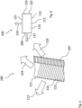
- a light guide 100 for a lighting element 200 such as a headlight, is shown.
- the light guide 100 comprises a luminous body 101, which comprises an interface 103 for coupling light rays through a light source 105.
- the luminous body 101 comprises a plurality of alignment elements 107, as in Fig. 2 which are each configured to emit light beams coupled into the luminous body 101 through a main emission surface 109 opposite the plurality of alignment elements 107 in a main emission direction, as indicated by arrow 109.
- the luminous element 101 comprises at least one secondary side surface 111 which extends laterally between the main radiating surface 109 and the number of alignment elements 107.
- the luminous element 101 comprises at least one side emission surface (not shown) which runs opposite the at least one secondary side surface 111, wherein the at least one secondary side surface 111 comprises a plurality of smooth transmission surfaces 113 and a plurality of rough surfaces 115.
- the side emission surface overexposes a side region, as indicated by arrows 119.
- This overexposed side region can, for example, span at least 80° of a circular arc, so that the light guide 100 is clearly recognizable as uniformly luminous from the entire side region, in particular between 1° and 90° laterally to the main emission direction.
- the transmission surfaces 113 are configured to transmit light rays within the luminous body 101.
- the rough surfaces 115 are configured to diffusely reflect light rays, so that at least a portion of light rays reflected by respective rough surfaces 115 exits the luminous element 101 through the side emission surface.
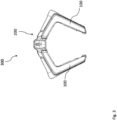
- a headlight 300 which comprises a lighting element 200 designed as a position light.
- the position light 200 comprises several light guides 100 according to Fig. 1 .
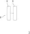
- the manufacturing method 400 comprises a provision step 401, in which a base body of a luminous element is provided, and an introduction step 403, in which roughened surfaces are introduced into the base body by means of a laser.
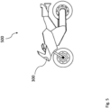
- a vehicle 500 in the form of a motorcycle is shown.
- the vehicle 500 includes the headlight 300 according to Fig. 3 .
- Fig. 6 shows a sectional view of the light guide 100 according to Fig. 2 In Fig. 6, in addition to the Fig. 2 the side emitting surface 121 and the back 123 of the light guide 100 are shown.
Landscapes
- Engineering & Computer Science (AREA)
- Physics & Mathematics (AREA)
- General Engineering & Computer Science (AREA)
- General Physics & Mathematics (AREA)
- Optics & Photonics (AREA)
- Mechanical Engineering (AREA)
- Non-Portable Lighting Devices Or Systems Thereof (AREA)
- Light Guides In General And Applications Therefor (AREA)
Abstract
wobei der Leuchtkörper (101) eine Schnittstelle (103) zum Einkoppeln von Lichtstrahlen umfasst.
Description
- Die vorgestellte Erfindung betrifft einen Lichtleiter für ein Leuchtelement, insbesondere ein Positionslicht, einen Scheinwerfer, ein Fahrzeug und ein Herstellungsverfahren gemäß den beigefügten Ansprüchen.
- Leuchtelemente, wie Positionslichter, für Fahrzeuge müssen aufgrund verkehrsrechtlicher Vorgaben sowohl in eine Hauptstrahlrichtung, bspw. entlang einer Fahrbahn, als auch seitlich, bspw. nach links und rechts der Fahrbahn bzw. in eine Peripherie der Fahrbahn leuchten.
- Dabei sollte ein Abstrahlwinkel eines Positionslichts bzw. einer Positionsleuchte einen seitlichen Abstrahlwinkel von 80° zu der Hauptstrahlrichtung erfüllen, sodass das Positionslicht auch von einer Position seitlich zu einem jeweiligen Fahrzeug gut erkennbar ist.
- Bekannte Positionslichter bzw. Begrenzungsleuchten sind für eine einzelne Seite eines Fahrzeugs optimiert und strahlen Licht in einer Hauptstrahlrichtung und einer einzelnen Seite ab. Entsprechend wirken in der Regel zwei Positionslichter zusammen, um in zwei Seiten Licht abzustrahlen.
- Ferner ist Bauraum insbesondere bei Krafträdern, wie bspw. Motorrädern, sehr begrenzt verfügbar.
- Der vorliegenden Erfindung liegt die Aufgabe zugrunde, ein kompaktes und sicheres Leuchtelement, insbesondere ein kompaktes und sicheres Positionslicht, für ein Fahrzeug bereitzustellen.
- Es wird somit gemäß einem ersten Aspekt der vorgestellten Erfindung ein Lichtleiter für ein Leuchtelement, insbesondere ein Positionslicht, vorgestellt.
- Der vorgestellte Lichtleiter umfasst einen Leuchtkörper, wobei der Leuchtkörper eine Schnittstelle zum Einkoppeln von Lichtstrahlen umfasst, wobei der Leuchtkörper eine Vielzahl Ausrichtungselemente umfasst, die jeweils dazu konfiguriert sind, in den Leuchtkörper eingekoppelte Lichtstrahlen durch eine der Vielzahl Ausrichtungselemente gegenüberliegende Hauptabstrahlfläche gerichtet in eine Hauptabstrahlrichtung abzustrahlen, wobei der Leuchtkörper zumindest eine Nebenseitenfläche umfasst, die seitlich zwischen der Hauptabstrahlfläche und der Anzahl Ausrichtungselemente verläuft, wobei der Leuchtkörper zumindest eine Seitenabstrahlfläche umfasst, die gegenüber der zumindest einen Nebenseitenfläche verläuft, wobei die zumindest eine Nebenseitenfläche eine Vielzahl glatte Weiterleitungsflächen und eine Vielzahl Rauflächen umfasst, wobei jeweilige Weiterleitungsflächen dazu konfiguriert sein, Lichtstrahlen innerhalb des Leuchtkörpers weiterzuleiten, wobei jeweilige Rauflächen dazu konfiguriert sind, Lichtstrahlen diffus zu reflektieren, sodass zumindest ein Teil von durch jeweilige Rauflächen reflektierten Lichtstrahlen durch die Seitenabstrahlfläche aus dem Leuchtkörper austritt.
- Unter einem Ausrichtungselement ist im Kontext der vorgestellten Erfindung ein optisches Element zu verstehen, das dazu konfiguriert ist, in das Ausrichtungselement einfallende Lichtstrahlen auszurichten bzw. zu brechen, sodass diese in eine vorgegebene Richtung gerichtet abgestrahlt werden.
- Unter einer Raufläche ist im Kontext der vorgestellten Erfindung eine Fläche auf dem Leuchtkörper des vorgestellten Lichtleiters zu verstehen, die eine gegenüber einer Klarfläche, wie bspw. der Hauptabstrahlfläche, erhöhte Rauheit zeigt. Dabei kann die Rauheit bspw. der durch die VDI 3400-33 vorgegebenen Rauheit entsprechen.
- Eine Raufläche kann bspw. eine Struktur, insbesondere eine Vielzahl von Erhebungen und Tälern aufweisen. Bspw. kann eine Raufläche schleifpapierartig sein, wohingegen eine Klarfläche bzw. Abstrahlfläche flach bzw. glatt, bspw. schreibpapierartig sein kann.
- Der vorgestellte Lichtleiter basiert auf dem Prinzip, dass dieser mehrere Abstrahlflächen zur Auskopplung bzw. zum Abstrahlen von Licht umfasst, nämlich zum einen eine Hauptabstrahlfläche, durch die gerichtete Lichtstrahlen in einer Hauptabstrahlrichtung abgestrahlt werden, und zum anderen eine Seitenabstrahlfläche, durch die von jeweiligen Rauflächen reflektierte Lichtstrahlen und zufällig durch den Leuchtkörper wandernde Lichtstrahlen ausgekoppelt bzw. abgestrahlt werden.
- Durch die Hauptabstrahlfläche ist der vorgestellte Lichtleiter aus einer Hauptrichtung, insbesondere von vorne als leuchtend erkennbar.
- Durch die Seitenabstrahlfläche ist der Lichtleiter aus einer Seitenrichtung, d. h., relativ zur Hauptrichtung seitlich versetzt, insbesondere in einem Bereich zwischen insbesondere 45° und mindestens 80° eines Kreisbogens seitlich versetzt zu der Hauptrichtung als leuchtend erkennbar.
- Aufgrund der erfindungsgemäß vorgesehenen Rauflächen werden in dem Leuchtkörper wandernde Lichtstrahlen diffus reflektiert, sodass diese zumindest teilweise auf eine Seitenabstrahlfläche treffen und dort aus dem Leuchtkörper austreten.
- Der erfindungsgemäß vorgesehene Leuchtkörper kann insbesondere aus transparentem Kunststoff bestehen. Bspw. kann der Leuchtkörper in einem Spritzgussprozess oder einem generativen Herstellungsverfahren bereitgestellt werden.
- Es kann vorgesehen sein, dass die Hauptabstrahlfläche eine Halbröhre bildet.
- Eine Halbröhre bewirkt ein Weiterleiten bzw. ein Wandern von Lichtstrahlen innerhalb des Leuchtkörpers durch Totalreflektion, sodass der gesamte Leuchtkörper mit
- Lichtstrahlen durchstrahlt wird und die gesamte Hauptabstrahlfläche sowie die gesamte Seitenabstrahlfläche leuchten.
- Ferner ermöglicht eine Hauptabstrahlfläche in Form einer Halbröhre eine Sichtbarkeit der Halbröhre aus einer Position seitlich zu einer Hauptabstrahlrichtung, insbesondere aus einer Position kleiner 80° zu einer Hauptabstrahlrichtung.
- Es kann weiterhin vorgesehen sein, dass der Leuchtkörper einen im Wesentlichen horizontal verlaufenden ersten Teil und einen im Wesentlichen vertikal verlaufenden zweiten Teil umfasst, wobei der erste Teil kürzer ist als der zweite Teil.
- Bspw. kann der Leuchtkörper L-förmig bzw. im Wesentlichen L-förmig ausgestaltet sein, sodass insbesondere an dem langen vertikalen Teil sich eine große Seitenabstrahlfläche ausbildet, die besonders gut aus einer Position seitlich zu dem Lichtleiter als leuchtend wahrgenommen werden kann.
- Es kann weiterhin vorgesehen sein, dass jeweilige Rauflächen rund, zumindest teilweise abgerundet, vieleckig, viereckig oder rechteckig, insbesondere streifenförmig ausgestaltet sind.
- Generell können die Rauflächen jede technisch geeignete Form aufweisen, solange sie Lichtstrahlen diffus reflektieren.
- Es kann weiterhin vorgesehen sein, dass die Vielzahl Rauflächen eine Anzahl streifenförmiger Rauflächen umfasst, die sich über eine gesamte Höhe einer Nebenseitenfläche zwischen der Hauptabstrahlfläche und einer die Vielzahl Ausrichtungselemente aufweisenden Rückseite erstrecken.
- Durch Rauflächen, die sich über eine gesamte Höhe einer Nebenseitenfläche erstrecken, wird ein großer Teil von durch den Leuchtkörper wandernden Lichtstrahlen eingefangen und diffus abgestrahlt.
- Es kann weiterhin vorgesehen sein, dass jeweilige Rauflächen durch jeweilige Weiterleitungsflächen voneinander beabstandet sind.
- Durch Weiterleitungsflächen wird sichergestellt, dass durch eine Lichtquelle an einer ersten Seite in den Lichtleiter eingekoppelte Lichtstrahlen auch in von der ersten Seite entfernte Stellen des Lichtleiters wandern. Dazu werden die Lichtstrahlen durch die Weiterleitungsflächen totalreflektiert. Entsprechend kann durch Rauflächen, die durch jeweilige Weiterleitungsflächen voneinander beabstandet sind, ein Kompromiss aus Leuchtkraft der Seitenabstrahlfläche und Leuchtkraft über den gesamten Lichtleiter hinweg erreicht werden. Dazu kann insbesondere eine Fläche jeweiliger Weiterleitungsflächen über die Länge des Leuchtkörpers hinweg variieren, sodass bspw. an einem dem ersten Ende gegenüberliegenden Ende keine bzw. nur minimale Weiterleitungsflächen ausgebildet sind und an dem ersten Ende maximale Weiterleitungsflächen ausgebildet sind.
- Gemäß einem zweiten Aspekt betrifft die vorgestellte Erfindung ein Leuchtelement, insbesondere ein Positionslicht, für ein Fahrzeug, wobei das Leuchtelement bzw. das Positionslicht eine Vielzahl möglicher Ausgestaltungen des vorgestellten Lichtleiters umfasst, wobei zumindest ein Lichtleiter mit seiner Abstrahlfläche zu einer ersten Seite des Positionslichts und zumindest ein weiterer Lichtleiter mit seiner Abstrahlfläche zu einer der ersten Seite gegenüberliegenden zweiten Seite ausgerichtet ist.
- Das vorgestellte Positionslicht ist aufgrund der erfindungsgemäßen Lichtleiter besonders gut aus einer Position seitlich zu einer Hauptabstrahlrichtung des Positionslichts als leuchtend zu erkennen.
- Insbesondere können die Lichtleiter des Positionslichts dazu konfiguriert sein, einen Bereich zwischen insbesondere 45° und mindestens 80° seitlich zu der Hauptabstrahlrichtung auszuleuchten.
- Gemäß einem dritten Aspekt betrifft die vorgestellte Erfindung einen Scheinwerfer für ein Fahrzeug, wobei der Scheinwerfer eine mögliche Ausgestaltung des vorgestellten Leuchtelements, insbesondere Positionslichts, umfasst.
- Der vorgestellte Scheinwerfer kann aufgrund des Positionslichts besonders kompakt ausgestaltet werden, sodass sich der vorgestellte Scheinwerfer besonders vorteilhaft zum Einsatz an Krafträdern, wie bspw. Motorrädern eignet.
- Gemäß einem vierten Aspekt betrifft die vorgestellte Erfindung ein Fahrzeug, wobei das Fahrzeug eine mögliche Ausgestaltung des vorgestellten Leuchtelements, in Form eines Positionslichts, oder eine mögliche Ausgestaltung des vorgestellten Scheinwerfers umfasst.
- Das vorgestellte Fahrzeug kann insbesondere ein Kraftrad sein.
- Gemäß einem fünften Aspekt betrifft die vorgestellte Erfindung ein Herstellungsverfahren für eine mögliche Ausgestaltung des vorgestellten Lichtleiters.
- Das vorgestellte Herstellungsverfahren umfasst das Bereitstellen eines Grundkörpers und das Einbringen von Rauflächen in den Grundkörper mittels eines Lasers.
- Durch einen Laser kann ein Leuchtkörper aus bspw. transparentem Kunststoff besonders effizient und exakt bearbeitet werden, sodass sich auf dem Leuchtkörper eine Vielzahl Rauflächen ausbildet.
- Anhand der beigefügten Zeichnungen wird die Erfindung nachfolgend näher erläutert. Dabei zeigen:
- Fig. 1
- eine mögliche Ausgestaltung des vorgestellten Lichtleiters,
- Fig. 2
- eine Detailansicht des Lichtleiters gemäß
Fig. 1 , - Fig. 3
- eine mögliche Ausgestaltung des vorgestellten Scheinwerfers, der eine mögliche Ausgestaltung des vorgestellten Leuchtelementes/Positionslichts mit dem Lichtleiter gemäß
Fig. 1 umfasst, - Fig. 4
- eine mögliche Ausgestaltung des vorgestellten Herstellungsverfahrens,
- Fig. 5
- eine mögliche Ausgestaltung des vorgestellten Fahrzeugs, und.
- Fig. 6
- eine Schnittdarstellung des Lichtleiters gemäß
Fig. 2 . - In
Fig. 1 ist ein Lichtleiter 100 für ein Leuchtelement 200, wie bspw. einen Scheinwerfer, dargestellt. - Der Lichtleiter 100 umfasst einen Leuchtkörper 101, der eine Schnittstelle 103 zum Einkoppeln von Lichtstrahlen durch eine Lichtquelle 105 umfasst.
- Ferner umfasst der Leuchtkörper 101 eine Vielzahl Ausrichtungselemente 107, wie in
Fig. 2 ersichtlich, die jeweils dazu konfiguriert sind, in den Leuchtkörper 101 eingekoppelte Lichtstrahlen durch eine der Vielzahl Ausrichtungselemente 107 gegenüberliegende Hauptabstrahlfläche 109 gerichtet in eine Hauptabstrahlrichtung, wie durch Pfeil 109 angedeutet, abzustrahlen. - Wie ebenfalls in
Fig. 2 ersichtlich, umfasst der Leuchtkörper 101 zumindest eine Nebenseitenfläche 111, die seitlich zwischen der Hauptabstrahlfläche 109 und der Anzahl Ausrichtungselemente 107 verläuft. - Ferner umfasst der Leuchtkörper 101 zumindest eine Seitenabstrahlfläche (nicht dargestellt), die gegenüber der zumindest einen Nebenseitenfläche 111 verläuft, wobei die zumindest eine Nebenseitenfläche 111 eine Vielzahl glatter Weiterleitungsflächen 113 und eine Vielzahl Rauflächen 115 umfasst.
- Die Seitenabstrahlfläche überstrahlt einen Seitenbereich, wie durch Pfeile 119 angedeutet. Dieser überstrahlte Seitenbereich kann bspw. mindestens 80° eines Kreisbogens umspannen, sodass der Lichtleiter 100 aus dem gesamten Seitenbereich, insbesondere zwischen 1° und 90° seitlich zur Hauptabstrahlrichtung, gut als gleichmäßig leuchtend erkennbar ist.
- Die Weiterleitungsflächen 113 sind dazu konfiguriert, Lichtstrahlen innerhalb des Leuchtkörpers 101 weiterzuleiten.
- Die Rauflächen 115 sind dazu konfiguriert, Lichtstrahlen diffus zu reflektieren, sodass zumindest ein Teil von durch jeweilige Rauflächen 115 reflektierten Lichtstrahlen durch die Seitenabstrahlfläche aus dem Leuchtkörper 101 austritt.
- In
Fig. 3 ist ein Scheinwerfer 300 dargestellt, der ein als Positionslicht ausgebildetes Leuchtelement 200 umfasst. Das Positionslicht 200 umfasst mehrere Lichtleiter 100 gemäßFig. 1 . - In
Fig. 4 ist ein Herstellungsverfahren 400 dargestellt. Das Herstellungsverfahren 400 umfasst einen Bereitstellungsschritt 401, bei dem ein Grundkörper eines Leuchtkörpers bereitgestellt wird und einen Einbringungsschritt 403, bei dem Rauflächen in den Grundkörper mittels eines Lasers eingebracht werden. - In
Fig. 5 ist ein Fahrzeug 500 in Form eines Kraftrads dargestellt. Das Fahrzeug 500 umfasst den Scheinwerfer 300 gemäßFig. 3 . - In Fig. 6 ist eine Schnittdarstellung des Lichtleiters 100 gemäß
Fig. 2 gezeigt. In Fig. 6 sind zusätzlich zurFig. 2 die Seitenabstrahlfläche 121 und die Rückseite 123 des Lichtleiters 100 dargestellt. -
- 100
- Lichtleiter
- 101
- Leuchtkörper
- 103
- Schnittstelle
- 105
- Lichtquelle
- 107
- Ausrichtungselement
- 109
- Hauptabstrahlfläche
- 111
- Nebenseitenfläche
- 113
- Weiterleitungsfläche
- 115
- Raufläche
- 117
- Pfeil
- 119
- Pfeil
- 200
- Leuchtelement/Positionslicht
- 300
- Scheinwerfer
- 400
- Herstellungsverfahren
- 401
- Bereitstellungsschritt
- 403
- Einbringungsschritt
Claims (11)
- Lichtleiter (100) für ein Leuchtelement (200),wobei der Lichtleiter (100) einen Leuchtkörper (101) umfasst,wobei der Leuchtkörper (101) eine Schnittstelle (103) zum Einkoppeln von Lichtstrahlen umfasst,wobei der Leuchtkörper (101) an einer Rückseite (123) eine Vielzahl Ausrichtungselemente (107) umfasst, die jeweils dazu konfiguriert sind, in den Leuchtkörper (101) eingekoppelte Lichtstrahlen durch eine der Vielzahl Ausrichtungselemente (107) gegenüberliegende Hauptabstrahlfläche (109) gerichtet in eine Hauptabstrahlrichtung (117) abzustrahlen,wobei der Leuchtkörper (101) zumindest eine Nebenseitenfläche (111) umfasst, die seitlich zwischen der Hauptabstrahlfläche (109) und der Anzahl Ausrichtungselemente (107) verläuft,wobei der Leuchtkörper (101) zumindest eine Seitenabstrahlfläche (121) umfasst, die gegenüber von der zumindest einen Nebenseitenfläche (111) verläuft,wobei zumindest eine Nebenseitenfläche (111) eine Vielzahl glatte Weiterleitungsflächen (113) und eine Vielzahl Rauflächen (115) umfasst,wobei jeweilige Weiterleitungsflächen (113) dazu konfiguriert sein, Lichtstrahlen innerhalb des Leuchtkörpers (101) weiterzuleiten,wobei jeweilige Rauflächen (115) dazu konfiguriert sind, Lichtstrahlen diffus zu reflektieren, sodass zumindest ein Teil von durch jeweilige Rauflächen (115) reflektierten Lichtstrahlen durch die Seitenabstrahlfläche (121) aus dem Leuchtkörper (101) austritt.
- Lichtleiter (100) nach Anspruch 1,
dadurch gekennzeichnet,
dass jeweilige Rauflächen (115) eine Rauheit gemäß VDI 3400-33 aufweisen. - Lichtleiter (100) nach Anspruch 1 oder 2,
dadurch gekennzeichnet,
dass die Hauptabstrahlfläche (109) eine Halbröhre bildet. - Lichtleiter (100) nach einem der voranstehenden Ansprüche,
dadurch gekennzeichnet,
dass der Leuchtkörper (101) einen im Wesentlichen horizontal verlaufenden ersten Teil und einen im Wesentlichen vertikal verlaufenden zweiten Teil umfasst, wobei der erste Teil kürzer ist als der zweite Teil. - Lichtleiter (100) nach einem der voranstehenden Ansprüche,
dadurch gekennzeichnet,
dass jeweilige Rauflächen (115) rund, zumindest teilweise abgerundet, vieleckig, viereckig oder rechteckig, insbesondere streifenförmig ausgestaltet sind. - Lichtleiter (100) nach einem der voranstehenden Ansprüche,
dadurch gekennzeichnet,
dass die Vielzahl Rauflächen (115) eine Anzahl streifenförmiger Rauflächen umfasst, die sich über eine gesamte Höhe einer Nebenseitenfläche (111) zwischen der Hauptabstrahlfläche (109) und einer die Vielzahl Ausrichtungselemente (107) aufweisenden Rückseite (123) erstrecken. - Lichtleiter (100) nach einem der voranstehenden Ansprüche,
dadurch gekennzeichnet,
dass jeweilige Rauflächen (115) durch jeweilige Weiterleitungsflächen (113) voneinander beabstandet sind. - Leuchtelement (200) für ein Fahrzeug,
wobei das Leuchtelement (200) eine Vielzahl Lichtleiter (100) nach einem der Ansprüche 1 bis 7 umfasst. - Scheinwerfer (300) für ein Fahrzeug,
wobei der Scheinwerfer (300) ein Leuchtelement (200) nach Anspruch 8 umfasst. - Fahrzeug (500),
wobei das Fahrzeug (500) ein Leuchtelement (200) nach Anspruch 8 oder einen Scheinwerfer (300) nach Anspruch 9 umfasst. - Herstellungsverfahren (400) für einen Lichtleiter (100) nach einem der Ansprüche 1 bis 7,
wobei das Herstellungsverfahren (400) umfasst:- Bereitstellen (401) eines Grundkörpers,- Einbringen (403) von Rauflächen in den Grundkörper mittels eines Lasers.
Applications Claiming Priority (1)
| Application Number | Priority Date | Filing Date | Title |
|---|---|---|---|
| DE102023129236.6A DE102023129236A1 (de) | 2023-10-24 | 2023-10-24 | Lichtleiter für ein Leuchtelement |
Publications (1)
| Publication Number | Publication Date |
|---|---|
| EP4545848A1 true EP4545848A1 (de) | 2025-04-30 |
Family
ID=93213676
Family Applications (1)
| Application Number | Title | Priority Date | Filing Date |
|---|---|---|---|
| EP24207711.3A Pending EP4545848A1 (de) | 2023-10-24 | 2024-10-21 | Lichtleiter für ein leuchtelement |
Country Status (4)
| Country | Link |
|---|---|
| US (1) | US12540713B2 (de) |
| EP (1) | EP4545848A1 (de) |
| CN (1) | CN119879116A (de) |
| DE (1) | DE102023129236A1 (de) |
Citations (9)
| Publication number | Priority date | Publication date | Assignee | Title |
|---|---|---|---|---|
| DE10149044A1 (de) * | 2001-10-05 | 2003-04-17 | Hella Kg Hueck & Co | Fahrzeugleuchte |
| US20090219731A1 (en) * | 2008-03-03 | 2009-09-03 | Valeo Vision | Optical system with main function for motor vehicle |
| US20150009696A1 (en) * | 2013-07-03 | 2015-01-08 | Panasonic Corporation | Lighting device, lighting fitting, and vehicle |
| KR20160077723A (ko) * | 2014-12-24 | 2016-07-04 | 에스엘 주식회사 | 차량용 램프 장치 |
| DE102016109957A1 (de) * | 2015-06-09 | 2016-12-15 | Zkw Group Gmbh | Lichtleiter für ein Kraftfahrzeug |
| CN108980773A (zh) * | 2018-10-19 | 2018-12-11 | 华域视觉科技(上海)有限公司 | 多角度导光体及用于车灯灯具 |
| WO2019134822A1 (en) * | 2018-01-02 | 2019-07-11 | Signify Holding B.V. | Luminaire comprising a surface tile and a lighting device |
| EP3550205A1 (de) * | 2018-04-04 | 2019-10-09 | ZKW Group GmbH | Lichtleiter für ein kraftfahrzeuglichtmodul |
| JP2021046005A (ja) * | 2019-09-17 | 2021-03-25 | 本田技研工業株式会社 | 鞍乗り型車両のポジションライト構造 |
Family Cites Families (2)
| Publication number | Priority date | Publication date | Assignee | Title |
|---|---|---|---|---|
| FR2776811B1 (fr) * | 1998-03-25 | 2001-12-14 | Christophe Blanc | Dispositif lumineux eclaire par la tranche |
| JP4006918B2 (ja) * | 2000-02-28 | 2007-11-14 | オムロン株式会社 | 面光源装置及びその製造方法 |
-
2023
- 2023-10-24 DE DE102023129236.6A patent/DE102023129236A1/de active Pending
-
2024
- 2024-10-16 US US18/917,375 patent/US12540713B2/en active Active
- 2024-10-21 EP EP24207711.3A patent/EP4545848A1/de active Pending
- 2024-10-23 CN CN202411481532.1A patent/CN119879116A/zh active Pending
Patent Citations (9)
| Publication number | Priority date | Publication date | Assignee | Title |
|---|---|---|---|---|
| DE10149044A1 (de) * | 2001-10-05 | 2003-04-17 | Hella Kg Hueck & Co | Fahrzeugleuchte |
| US20090219731A1 (en) * | 2008-03-03 | 2009-09-03 | Valeo Vision | Optical system with main function for motor vehicle |
| US20150009696A1 (en) * | 2013-07-03 | 2015-01-08 | Panasonic Corporation | Lighting device, lighting fitting, and vehicle |
| KR20160077723A (ko) * | 2014-12-24 | 2016-07-04 | 에스엘 주식회사 | 차량용 램프 장치 |
| DE102016109957A1 (de) * | 2015-06-09 | 2016-12-15 | Zkw Group Gmbh | Lichtleiter für ein Kraftfahrzeug |
| WO2019134822A1 (en) * | 2018-01-02 | 2019-07-11 | Signify Holding B.V. | Luminaire comprising a surface tile and a lighting device |
| EP3550205A1 (de) * | 2018-04-04 | 2019-10-09 | ZKW Group GmbH | Lichtleiter für ein kraftfahrzeuglichtmodul |
| CN108980773A (zh) * | 2018-10-19 | 2018-12-11 | 华域视觉科技(上海)有限公司 | 多角度导光体及用于车灯灯具 |
| JP2021046005A (ja) * | 2019-09-17 | 2021-03-25 | 本田技研工業株式会社 | 鞍乗り型車両のポジションライト構造 |
Also Published As
| Publication number | Publication date |
|---|---|
| US20250129908A1 (en) | 2025-04-24 |
| DE102023129236A1 (de) | 2025-04-24 |
| US12540713B2 (en) | 2026-02-03 |
| CN119879116A (zh) | 2025-04-25 |
Similar Documents
| Publication | Publication Date | Title |
|---|---|---|
| EP1640656B1 (de) | Lichtleiter für Leuchten, insbesondere für Leuchten von Kraftfahrzeugen | |
| EP1033526B1 (de) | Leuchte, insbesondere für Kraftfahrzeuge | |
| EP0933587B1 (de) | Stabförmiger Lichtleiter | |
| DE102013100557B4 (de) | Beleuchtungsvorrichtung für Fahrzeuge | |
| DE102014112367B4 (de) | Scheinwerfervorrichtung für Fahrzeuge | |
| DE102008038668B4 (de) | Signalleuchte für Fahrzeuge, die eine Mehrzahl von parallel zueinander verlaufenden Lichtleitelementen und einen Reflektor aufweist | |
| EP4146983B1 (de) | Beleuchtungsvorrichtung für ein kraftfahrzeug | |
| DE10356483B4 (de) | Fahrzeugaußenspiegel-Leuchte eines Kraftfahrzeugs | |
| DE102011055429B4 (de) | Beleuchtungsvorrichtung für Fahrzeuge | |
| DE102013104174A1 (de) | Beleuchtungsvorrichtung für Fahrzeuge | |
| EP2502784B1 (de) | Fahrzeugleuchte, insbesondere zur Beleuchtung des Innenraums des Fahrzeugs | |
| DE102021134644B4 (de) | Leuchte für ein fahrzeug, die einen lichtleiterteil mit einer ausnehmung mit einem hell-dunkel-grenzbereich in stufenform aufweist, und fahrzeug mit einer solchen | |
| EP0933588A2 (de) | Leuchte für Fahrzeuge | |
| EP3210827A1 (de) | Leuchte für kraftfahrzeuge | |
| EP1154198B1 (de) | Stabförmiger Lichtleiter | |
| DE102015115969B4 (de) | Beleuchtungsvorrichtung für Fahrzeuge | |
| DE102023134159A1 (de) | Fahrzeugleuchte | |
| EP1898147B1 (de) | Beleuchtungseinrichtung für Fahrzeuge | |
| DE19806526A1 (de) | Beleuchtungseinrichtung für Kraftfahrzeuge | |
| EP1146281B1 (de) | Signalleuchte mit mindestens einem Leuchtmittel und einem Lichtleiter | |
| EP2119956B1 (de) | Scheinwerfer für ein Kraftfahrzeug mit einem Ringabstrahlkörper | |
| EP2108883B1 (de) | Signalleuchte für Kraftfahrzeuge | |
| DE102016109957A1 (de) | Lichtleiter für ein Kraftfahrzeug | |
| DE102023129236A1 (de) | Lichtleiter für ein Leuchtelement | |
| DE102023124550B3 (de) | Scheinwerfer für Fahrzeuge |
Legal Events
| Date | Code | Title | Description |
|---|---|---|---|
| PUAI | Public reference made under article 153(3) epc to a published international application that has entered the european phase |
Free format text: ORIGINAL CODE: 0009012 |
|
| STAA | Information on the status of an ep patent application or granted ep patent |
Free format text: STATUS: THE APPLICATION HAS BEEN PUBLISHED |
|
| AK | Designated contracting states |
Kind code of ref document: A1 Designated state(s): AL AT BE BG CH CY CZ DE DK EE ES FI FR GB GR HR HU IE IS IT LI LT LU LV MC ME MK MT NL NO PL PT RO RS SE SI SK SM TR |
|
| STAA | Information on the status of an ep patent application or granted ep patent |
Free format text: STATUS: REQUEST FOR EXAMINATION WAS MADE |
|
| RAP3 | Party data changed (applicant data changed or rights of an application transferred) |
Owner name: HELLA GMBH & CO. KGAA |
|
| 17P | Request for examination filed |
Effective date: 20250903 |
|
| STAA | Information on the status of an ep patent application or granted ep patent |
Free format text: STATUS: EXAMINATION IS IN PROGRESS |
|
| RIC1 | Information provided on ipc code assigned before grant |
Ipc: F21S 43/237 20180101AFI20251211BHEP Ipc: B62J 6/022 20200101ALI20251211BHEP Ipc: F21S 43/245 20180101ALI20251211BHEP Ipc: F21S 43/242 20180101ALI20251211BHEP |
|
| 17Q | First examination report despatched |
Effective date: 20251218 |