EP4545804A1 - Hydraulische anordnung und nutzfahrzeug - Google Patents
Hydraulische anordnung und nutzfahrzeug Download PDFInfo
- Publication number
- EP4545804A1 EP4545804A1 EP24196178.8A EP24196178A EP4545804A1 EP 4545804 A1 EP4545804 A1 EP 4545804A1 EP 24196178 A EP24196178 A EP 24196178A EP 4545804 A1 EP4545804 A1 EP 4545804A1
- Authority
- EP
- European Patent Office
- Prior art keywords
- hydraulic
- connection
- flow path
- valve
- valve unit
- Prior art date
- Legal status (The legal status is an assumption and is not a legal conclusion. Google has not performed a legal analysis and makes no representation as to the accuracy of the status listed.)
- Pending
Links
Images


Classifications
-
- F—MECHANICAL ENGINEERING; LIGHTING; HEATING; WEAPONS; BLASTING
- F15—FLUID-PRESSURE ACTUATORS; HYDRAULICS OR PNEUMATICS IN GENERAL
- F15B—SYSTEMS ACTING BY MEANS OF FLUIDS IN GENERAL; FLUID-PRESSURE ACTUATORS, e.g. SERVOMOTORS; DETAILS OF FLUID-PRESSURE SYSTEMS, NOT OTHERWISE PROVIDED FOR
- F15B7/00—Systems in which the movement produced is definitely related to the output of a volumetric pump; Telemotors
- F15B7/005—With rotary or crank input
- F15B7/006—Rotary pump input
-
- F—MECHANICAL ENGINEERING; LIGHTING; HEATING; WEAPONS; BLASTING
- F15—FLUID-PRESSURE ACTUATORS; HYDRAULICS OR PNEUMATICS IN GENERAL
- F15B—SYSTEMS ACTING BY MEANS OF FLUIDS IN GENERAL; FLUID-PRESSURE ACTUATORS, e.g. SERVOMOTORS; DETAILS OF FLUID-PRESSURE SYSTEMS, NOT OTHERWISE PROVIDED FOR
- F15B11/00—Servomotor systems without provision for follow-up action; Circuits therefor
- F15B11/02—Systems essentially incorporating special features for controlling the speed or actuating force of an output member
- F15B11/04—Systems essentially incorporating special features for controlling the speed or actuating force of an output member for controlling the speed
- F15B11/042—Systems essentially incorporating special features for controlling the speed or actuating force of an output member for controlling the speed by means in the feed line, i.e. "meter in"
- F15B11/0423—Systems essentially incorporating special features for controlling the speed or actuating force of an output member for controlling the speed by means in the feed line, i.e. "meter in" by controlling pump output or bypass, other than to maintain constant speed
-
- F—MECHANICAL ENGINEERING; LIGHTING; HEATING; WEAPONS; BLASTING
- F15—FLUID-PRESSURE ACTUATORS; HYDRAULICS OR PNEUMATICS IN GENERAL
- F15B—SYSTEMS ACTING BY MEANS OF FLUIDS IN GENERAL; FLUID-PRESSURE ACTUATORS, e.g. SERVOMOTORS; DETAILS OF FLUID-PRESSURE SYSTEMS, NOT OTHERWISE PROVIDED FOR
- F15B11/00—Servomotor systems without provision for follow-up action; Circuits therefor
- F15B11/16—Servomotor systems without provision for follow-up action; Circuits therefor with two or more servomotors
- F15B11/161—Servomotor systems without provision for follow-up action; Circuits therefor with two or more servomotors with sensing of servomotor demand or load
- F15B11/165—Servomotor systems without provision for follow-up action; Circuits therefor with two or more servomotors with sensing of servomotor demand or load for adjusting the pump output or bypass in response to demand
-
- F—MECHANICAL ENGINEERING; LIGHTING; HEATING; WEAPONS; BLASTING
- F15—FLUID-PRESSURE ACTUATORS; HYDRAULICS OR PNEUMATICS IN GENERAL
- F15B—SYSTEMS ACTING BY MEANS OF FLUIDS IN GENERAL; FLUID-PRESSURE ACTUATORS, e.g. SERVOMOTORS; DETAILS OF FLUID-PRESSURE SYSTEMS, NOT OTHERWISE PROVIDED FOR
- F15B21/00—Common features of fluid actuator systems; Fluid-pressure actuator systems or details thereof, not covered by any other group of this subclass
- F15B21/04—Special measures taken in connection with the properties of the fluid
- F15B21/045—Compensating for variations in viscosity or temperature
-
- E—FIXED CONSTRUCTIONS
- E02—HYDRAULIC ENGINEERING; FOUNDATIONS; SOIL SHIFTING
- E02F—DREDGING; SOIL-SHIFTING
- E02F9/00—Component parts of dredgers or soil-shifting machines, not restricted to one of the kinds covered by groups E02F3/00 - E02F7/00
- E02F9/20—Drives; Control devices
- E02F9/22—Hydraulic or pneumatic drives
- E02F9/2221—Control of flow rate; Load sensing arrangements
- E02F9/2225—Control of flow rate; Load sensing arrangements using pressure-compensating valves
- E02F9/2228—Control of flow rate; Load sensing arrangements using pressure-compensating valves including an electronic controller
-
- E—FIXED CONSTRUCTIONS
- E02—HYDRAULIC ENGINEERING; FOUNDATIONS; SOIL SHIFTING
- E02F—DREDGING; SOIL-SHIFTING
- E02F9/00—Component parts of dredgers or soil-shifting machines, not restricted to one of the kinds covered by groups E02F3/00 - E02F7/00
- E02F9/20—Drives; Control devices
- E02F9/22—Hydraulic or pneumatic drives
- E02F9/2221—Control of flow rate; Load sensing arrangements
- E02F9/2232—Control of flow rate; Load sensing arrangements using one or more variable displacement pumps
- E02F9/2235—Control of flow rate; Load sensing arrangements using one or more variable displacement pumps including an electronic controller
-
- F—MECHANICAL ENGINEERING; LIGHTING; HEATING; WEAPONS; BLASTING
- F15—FLUID-PRESSURE ACTUATORS; HYDRAULICS OR PNEUMATICS IN GENERAL
- F15B—SYSTEMS ACTING BY MEANS OF FLUIDS IN GENERAL; FLUID-PRESSURE ACTUATORS, e.g. SERVOMOTORS; DETAILS OF FLUID-PRESSURE SYSTEMS, NOT OTHERWISE PROVIDED FOR
- F15B2211/00—Circuits for servomotor systems
- F15B2211/20—Fluid pressure source, e.g. accumulator or variable axial piston pump
- F15B2211/205—Systems with pumps
- F15B2211/20507—Type of prime mover
- F15B2211/20523—Internal combustion engine
-
- F—MECHANICAL ENGINEERING; LIGHTING; HEATING; WEAPONS; BLASTING
- F15—FLUID-PRESSURE ACTUATORS; HYDRAULICS OR PNEUMATICS IN GENERAL
- F15B—SYSTEMS ACTING BY MEANS OF FLUIDS IN GENERAL; FLUID-PRESSURE ACTUATORS, e.g. SERVOMOTORS; DETAILS OF FLUID-PRESSURE SYSTEMS, NOT OTHERWISE PROVIDED FOR
- F15B2211/00—Circuits for servomotor systems
- F15B2211/20—Fluid pressure source, e.g. accumulator or variable axial piston pump
- F15B2211/205—Systems with pumps
- F15B2211/2053—Type of pump
- F15B2211/20546—Type of pump variable capacity
-
- F—MECHANICAL ENGINEERING; LIGHTING; HEATING; WEAPONS; BLASTING
- F15—FLUID-PRESSURE ACTUATORS; HYDRAULICS OR PNEUMATICS IN GENERAL
- F15B—SYSTEMS ACTING BY MEANS OF FLUIDS IN GENERAL; FLUID-PRESSURE ACTUATORS, e.g. SERVOMOTORS; DETAILS OF FLUID-PRESSURE SYSTEMS, NOT OTHERWISE PROVIDED FOR
- F15B2211/00—Circuits for servomotor systems
- F15B2211/20—Fluid pressure source, e.g. accumulator or variable axial piston pump
- F15B2211/205—Systems with pumps
- F15B2211/2053—Type of pump
- F15B2211/20546—Type of pump variable capacity
- F15B2211/20553—Type of pump variable capacity with pilot circuit, e.g. for controlling a swash plate
-
- F—MECHANICAL ENGINEERING; LIGHTING; HEATING; WEAPONS; BLASTING
- F15—FLUID-PRESSURE ACTUATORS; HYDRAULICS OR PNEUMATICS IN GENERAL
- F15B—SYSTEMS ACTING BY MEANS OF FLUIDS IN GENERAL; FLUID-PRESSURE ACTUATORS, e.g. SERVOMOTORS; DETAILS OF FLUID-PRESSURE SYSTEMS, NOT OTHERWISE PROVIDED FOR
- F15B2211/00—Circuits for servomotor systems
- F15B2211/30—Directional control
- F15B2211/32—Directional control characterised by the type of actuation
- F15B2211/327—Directional control characterised by the type of actuation electrically or electronically
-
- F—MECHANICAL ENGINEERING; LIGHTING; HEATING; WEAPONS; BLASTING
- F15—FLUID-PRESSURE ACTUATORS; HYDRAULICS OR PNEUMATICS IN GENERAL
- F15B—SYSTEMS ACTING BY MEANS OF FLUIDS IN GENERAL; FLUID-PRESSURE ACTUATORS, e.g. SERVOMOTORS; DETAILS OF FLUID-PRESSURE SYSTEMS, NOT OTHERWISE PROVIDED FOR
- F15B2211/00—Circuits for servomotor systems
- F15B2211/40—Flow control
- F15B2211/415—Flow control characterised by the connections of the flow control means in the circuit
- F15B2211/41509—Flow control characterised by the connections of the flow control means in the circuit being connected to a pressure source and a directional control valve
-
- F—MECHANICAL ENGINEERING; LIGHTING; HEATING; WEAPONS; BLASTING
- F15—FLUID-PRESSURE ACTUATORS; HYDRAULICS OR PNEUMATICS IN GENERAL
- F15B—SYSTEMS ACTING BY MEANS OF FLUIDS IN GENERAL; FLUID-PRESSURE ACTUATORS, e.g. SERVOMOTORS; DETAILS OF FLUID-PRESSURE SYSTEMS, NOT OTHERWISE PROVIDED FOR
- F15B2211/00—Circuits for servomotor systems
- F15B2211/40—Flow control
- F15B2211/415—Flow control characterised by the connections of the flow control means in the circuit
- F15B2211/41563—Flow control characterised by the connections of the flow control means in the circuit being connected to a pressure source and a return line
-
- F—MECHANICAL ENGINEERING; LIGHTING; HEATING; WEAPONS; BLASTING
- F15—FLUID-PRESSURE ACTUATORS; HYDRAULICS OR PNEUMATICS IN GENERAL
- F15B—SYSTEMS ACTING BY MEANS OF FLUIDS IN GENERAL; FLUID-PRESSURE ACTUATORS, e.g. SERVOMOTORS; DETAILS OF FLUID-PRESSURE SYSTEMS, NOT OTHERWISE PROVIDED FOR
- F15B2211/00—Circuits for servomotor systems
- F15B2211/40—Flow control
- F15B2211/42—Flow control characterised by the type of actuation
- F15B2211/426—Flow control characterised by the type of actuation electrically or electronically
-
- F—MECHANICAL ENGINEERING; LIGHTING; HEATING; WEAPONS; BLASTING
- F15—FLUID-PRESSURE ACTUATORS; HYDRAULICS OR PNEUMATICS IN GENERAL
- F15B—SYSTEMS ACTING BY MEANS OF FLUIDS IN GENERAL; FLUID-PRESSURE ACTUATORS, e.g. SERVOMOTORS; DETAILS OF FLUID-PRESSURE SYSTEMS, NOT OTHERWISE PROVIDED FOR
- F15B2211/00—Circuits for servomotor systems
- F15B2211/50—Pressure control
- F15B2211/505—Pressure control characterised by the type of pressure control means
- F15B2211/50509—Pressure control characterised by the type of pressure control means the pressure control means controlling a pressure upstream of the pressure control means
- F15B2211/50518—Pressure control characterised by the type of pressure control means the pressure control means controlling a pressure upstream of the pressure control means using pressure relief valves
-
- F—MECHANICAL ENGINEERING; LIGHTING; HEATING; WEAPONS; BLASTING
- F15—FLUID-PRESSURE ACTUATORS; HYDRAULICS OR PNEUMATICS IN GENERAL
- F15B—SYSTEMS ACTING BY MEANS OF FLUIDS IN GENERAL; FLUID-PRESSURE ACTUATORS, e.g. SERVOMOTORS; DETAILS OF FLUID-PRESSURE SYSTEMS, NOT OTHERWISE PROVIDED FOR
- F15B2211/00—Circuits for servomotor systems
- F15B2211/50—Pressure control
- F15B2211/505—Pressure control characterised by the type of pressure control means
- F15B2211/50509—Pressure control characterised by the type of pressure control means the pressure control means controlling a pressure upstream of the pressure control means
- F15B2211/50536—Pressure control characterised by the type of pressure control means the pressure control means controlling a pressure upstream of the pressure control means using unloading valves controlling the supply pressure by diverting fluid to the return line
-
- F—MECHANICAL ENGINEERING; LIGHTING; HEATING; WEAPONS; BLASTING
- F15—FLUID-PRESSURE ACTUATORS; HYDRAULICS OR PNEUMATICS IN GENERAL
- F15B—SYSTEMS ACTING BY MEANS OF FLUIDS IN GENERAL; FLUID-PRESSURE ACTUATORS, e.g. SERVOMOTORS; DETAILS OF FLUID-PRESSURE SYSTEMS, NOT OTHERWISE PROVIDED FOR
- F15B2211/00—Circuits for servomotor systems
- F15B2211/50—Pressure control
- F15B2211/52—Pressure control characterised by the type of actuation
- F15B2211/526—Pressure control characterised by the type of actuation electrically or electronically
-
- F—MECHANICAL ENGINEERING; LIGHTING; HEATING; WEAPONS; BLASTING
- F15—FLUID-PRESSURE ACTUATORS; HYDRAULICS OR PNEUMATICS IN GENERAL
- F15B—SYSTEMS ACTING BY MEANS OF FLUIDS IN GENERAL; FLUID-PRESSURE ACTUATORS, e.g. SERVOMOTORS; DETAILS OF FLUID-PRESSURE SYSTEMS, NOT OTHERWISE PROVIDED FOR
- F15B2211/00—Circuits for servomotor systems
- F15B2211/60—Circuit components or control therefor
- F15B2211/605—Load sensing circuits
- F15B2211/6051—Load sensing circuits having valve means between output member and the load sensing circuit
-
- F—MECHANICAL ENGINEERING; LIGHTING; HEATING; WEAPONS; BLASTING
- F15—FLUID-PRESSURE ACTUATORS; HYDRAULICS OR PNEUMATICS IN GENERAL
- F15B—SYSTEMS ACTING BY MEANS OF FLUIDS IN GENERAL; FLUID-PRESSURE ACTUATORS, e.g. SERVOMOTORS; DETAILS OF FLUID-PRESSURE SYSTEMS, NOT OTHERWISE PROVIDED FOR
- F15B2211/00—Circuits for servomotor systems
- F15B2211/60—Circuit components or control therefor
- F15B2211/605—Load sensing circuits
- F15B2211/6051—Load sensing circuits having valve means between output member and the load sensing circuit
- F15B2211/6057—Load sensing circuits having valve means between output member and the load sensing circuit using directional control valves
-
- F—MECHANICAL ENGINEERING; LIGHTING; HEATING; WEAPONS; BLASTING
- F15—FLUID-PRESSURE ACTUATORS; HYDRAULICS OR PNEUMATICS IN GENERAL
- F15B—SYSTEMS ACTING BY MEANS OF FLUIDS IN GENERAL; FLUID-PRESSURE ACTUATORS, e.g. SERVOMOTORS; DETAILS OF FLUID-PRESSURE SYSTEMS, NOT OTHERWISE PROVIDED FOR
- F15B2211/00—Circuits for servomotor systems
- F15B2211/60—Circuit components or control therefor
- F15B2211/61—Secondary circuits
- F15B2211/611—Diverting circuits, e.g. for cooling or filtering
-
- F—MECHANICAL ENGINEERING; LIGHTING; HEATING; WEAPONS; BLASTING
- F15—FLUID-PRESSURE ACTUATORS; HYDRAULICS OR PNEUMATICS IN GENERAL
- F15B—SYSTEMS ACTING BY MEANS OF FLUIDS IN GENERAL; FLUID-PRESSURE ACTUATORS, e.g. SERVOMOTORS; DETAILS OF FLUID-PRESSURE SYSTEMS, NOT OTHERWISE PROVIDED FOR
- F15B2211/00—Circuits for servomotor systems
- F15B2211/60—Circuit components or control therefor
- F15B2211/65—Methods of control of the load sensing pressure
- F15B2211/654—Methods of control of the load sensing pressure the load sensing pressure being lower than the load pressure
-
- F—MECHANICAL ENGINEERING; LIGHTING; HEATING; WEAPONS; BLASTING
- F15—FLUID-PRESSURE ACTUATORS; HYDRAULICS OR PNEUMATICS IN GENERAL
- F15B—SYSTEMS ACTING BY MEANS OF FLUIDS IN GENERAL; FLUID-PRESSURE ACTUATORS, e.g. SERVOMOTORS; DETAILS OF FLUID-PRESSURE SYSTEMS, NOT OTHERWISE PROVIDED FOR
- F15B2211/00—Circuits for servomotor systems
- F15B2211/60—Circuit components or control therefor
- F15B2211/665—Methods of control using electronic components
- F15B2211/6652—Control of the pressure source, e.g. control of the swash plate angle
-
- F—MECHANICAL ENGINEERING; LIGHTING; HEATING; WEAPONS; BLASTING
- F15—FLUID-PRESSURE ACTUATORS; HYDRAULICS OR PNEUMATICS IN GENERAL
- F15B—SYSTEMS ACTING BY MEANS OF FLUIDS IN GENERAL; FLUID-PRESSURE ACTUATORS, e.g. SERVOMOTORS; DETAILS OF FLUID-PRESSURE SYSTEMS, NOT OTHERWISE PROVIDED FOR
- F15B2211/00—Circuits for servomotor systems
- F15B2211/60—Circuit components or control therefor
- F15B2211/665—Methods of control using electronic components
- F15B2211/6654—Flow rate control
-
- F—MECHANICAL ENGINEERING; LIGHTING; HEATING; WEAPONS; BLASTING
- F15—FLUID-PRESSURE ACTUATORS; HYDRAULICS OR PNEUMATICS IN GENERAL
- F15B—SYSTEMS ACTING BY MEANS OF FLUIDS IN GENERAL; FLUID-PRESSURE ACTUATORS, e.g. SERVOMOTORS; DETAILS OF FLUID-PRESSURE SYSTEMS, NOT OTHERWISE PROVIDED FOR
- F15B2211/00—Circuits for servomotor systems
- F15B2211/80—Other types of control related to particular problems or conditions
- F15B2211/85—Control during special operating conditions
- F15B2211/851—Control during special operating conditions during starting
Definitions
- the invention relates to a hydraulic arrangement for a commercial vehicle with a hydraulic variable displacement pump for supplying hydraulic consumers of the commercial vehicle. Furthermore, the invention relates to a commercial vehicle with such a hydraulic arrangement.
- variable displacement pumps In tractors, it is common practice to use variable displacement pumps to supply internal or external hydraulic consumers.
- the variable displacement pump is driven, preferably via a gearbox, by the drive engine of the commercial vehicle or tractor.
- the control system of the variable displacement pump When the drive engine is started, the control system of the variable displacement pump is often set to a maximum delivery position, i.e., to deliver a maximum hydraulic flow. This requires a correspondingly high drive power from the drive engine.
- a cold start of the commercial vehicle can further increase the power consumption of the variable displacement pump due to the increased viscosity of the hydraulic fluid.
- the present invention is based on the object of proposing a hydraulic arrangement and a commercial vehicle which reduces the power required for the variable displacement pump when starting the commercial vehicle.
- a hydraulic arrangement for a commercial vehicle which contains a hydraulic variable displacement pump, to whose pump outlet a supply connection is connected or connectable as an interface for supplying hydraulic consumers. These can be consumers inside the vehicle and possibly also external to the vehicle (e.g. of an attachment). Furthermore, a feedback connection is provided on the hydraulic arrangement as an interface for pressure feedback from consumers.
- the variable displacement pump can be adjusted with regard to its delivery rate or volume flow by an adjustment control which is dependent on an output pressure of the variable displacement pump, a signal pressure of the feedback connection and optionally on one or more further physical variables.
- the hydraulic arrangement contains a hydraulic valve device in the flow path between the feedback connection and the adjustment control.
- variable displacement pumps With variable displacement pumps, the delivery rate or volume flow of the pumped hydraulic medium (e.g., oil) can be adjusted not only by varying the drive speed, but also at a constant drive speed of the variable displacement pump.
- Various parameters can be used as control variables, e.g., the current hydraulic pressure, particularly at the variable displacement pump outlet and/or at a hydraulic feedback connection to which a hydraulic signaling pressure or load signaling pressure from hydraulic consumers is applied.
- the respective control variable(s) can influence a suitable control system, which adjusts the variable displacement pump's delivery rate, particularly continuously.
- the adjustment control can be switched between a conveying position with a maximum conveying quantity and a conveying position with a minimum flow rate.
- a hydraulic adjustment cylinder is preferably used for this purpose.
- the valve device according to claim 1 contains a valve unit, the actuation of which allows the activation of specific switching positions. This makes it technically efficient to limit or reduce the output pressure and/or the delivery rate or volume flow of the variable displacement pump during a starting process, in particular to reduce them to a minimum. Consequently, the power consumption of the variable displacement pump is advantageously limited or reduced.
- suitable actuation of the valve device or the valve unit contained therein in connection with an intended starting process of the commercial vehicle can reduce the power required by the drive motor for the variable displacement pump. In this way, lower power from the drive motor is required during the starting process. Consequently, the drive motor and the starter motor of the commercial vehicle can be relieved during a starting phase and supported with low energy losses.
- the load on the variable displacement pump and the drive motor as well as the starter motor of the commercial vehicle is relieved.
- the starting process of the commercial vehicle can be carried out with significantly lower power requirements, which also supports the technical process of a successful cold start.
- the valve assembly used eliminates the need for an auxiliary pump to support the variable displacement pump.
- the hydraulic arrangement can therefore be constructed more cost-effectively and with a smaller overall volume.
- the valve device contains a valve unit hydraulically interposed in the flow path.
- the valve unit interposed in the flow path In a first switching position, or initial or rest position, the valve unit acts as a hydraulic connection in the flow path between the feedback port and the adjustment control, and in a second switching position, it acts as a hydraulic interruption in this flow path.
- the valve device With the different switching positions of its valve unit that can be activated, the valve device provides a technically simple and cost-effective solution for the desired power reduction during the start-up process of the commercial vehicle.
- variable displacement pump In the second switching position of the valve unit, no load can be sensed on the variable displacement pump or the variable displacement control, so that the variable displacement pump only generates a relatively low standby pressure and consequently has only a low power consumption.
- the aforementioned tank connection acts as a hydraulic interface to which a hydraulic tank can be connected.
- the hydraulic tank serves as a reservoir for hydraulic fluid (e.g., oil) within the hydraulic circuit under consideration.
- the hydraulic arrangement can contain multiple tank connections as hydraulic interfaces.
- the pump outlet or variable displacement pump outlet can be a hydraulic outlet directly on the variable displacement pump itself or can be designed as a hydraulic outlet of a pump unit containing the variable displacement pump.
- the valve unit of the valve device arranged in the flow path between the feedback connection and the adjustment control has a single valve connection at least on the connection side facing the adjustment control.
- the valve unit is designed as a 2/2-way valve.
- the valve device can act as a simple interruption between the adjustment control and the feedback connection in the second switching position of the valve unit.
- the output pressure of the variable displacement pump only rises to a standby pressure due to the lack of load sensing.
- the standby pressure can, if necessary, influence the adjustment control in such a way that a delivery position with a minimum delivery rate is set on the variable displacement pump. This makes it possible to limit at least the output pressure of the variable displacement pump and, if necessary, also the delivery rate during the start-up process, which reduces the power consumption of the variable displacement pump.
- the valve unit in another advantageous embodiment of the valve unit arranged in the flow path between the adjustment control and the feedback connection, has two valve connections on the connection side facing away from the adjustment control, one of which is permanently hydraulically connected to a tank connection. Consequently, even under varying hydraulic boundary conditions, it is ensured that only a very low tank pressure is present at the corresponding adjustment control input in the second switching position of the valve unit. This supports the generation of a low output pressure at the variable displacement pump during the starting process. This allows the drive power required for the variable displacement pump to be kept very low during the starting phase of the commercial vehicle.
- the hydraulic arrangement additionally contains a hydraulic valve device in the flow path between the pump outlet and the supply connection.
- the valve device contains a valve unit hydraulically interposed in the flow path and/or a valve unit hydraulically branching off on the flow path to a tank connection.
- the valve unit interposed in the flow path acts as a hydraulic connection in the flow path in a first switching position or initial or rest position and as a hydraulic interruption in the flow path in a second switching position.
- the valve unit connected to the flow path as a branch to a tank connection acts as a hydraulic interruption to the tank connection in a rest position or first switching position and as a hydraulic connection to the tank connection in a second switching position.
- the combination of the two valve devices in the hydraulic arrangement supports the desired power reduction during a start-up process of the commercial vehicle.
- the pump outlet of the variable displacement pump is hydraulically connectable to a tank connection or is hydraulically connected when the valve unit arranged in the flow path between the pump outlet and the supply connection assumes its second switching position.
- a valve connection is permanently hydraulically connected to a tank connection. The hydraulic connection to the tank connection enables a very low tank pressure at the pump outlet. This allows the drive power required for the variable displacement pump to be kept very low during the start-up phase of the commercial vehicle, even if the outlet pressure is insufficient to influence the adjustment control towards a reduced delivery rate.
- the nominal pressure is dependent on the output pressure at the pump outlet.
- a connection to the tank connection can limit the pressure increase of the variable displacement pump and thus its power consumption during the start-up phase of the commercial vehicle.
- the nominal pressure can be selected such that it corresponds to a sufficiently high output pressure of the variable displacement pump, which, by means of the adjustment control, achieves the delivery position with the minimum delivery rate and thus a further reduction in the required pump power. This can be achieved, for example, with a pressure relief valve interposed between the aforementioned valve connection and the tank connection, the return spring of which is dimensioned or adjustable to the nominal pressure.
- the hydraulic valve unit arranged in the flow path between the pump outlet of the variable displacement pump and the supply connection has a single valve connection at least on the connection side facing the pump outlet.
- the valve unit is designed as a 2/2-way valve.
- the valve device can act as a simple interruption between the variable displacement pump and the supply connection in the second switching position of the valve unit.
- the output pressure of the variable displacement pump only rises to a standby pressure, which automatically influences the adjustment control such that a delivery position with a minimum delivery rate is set on the variable displacement pump.
- both the output pressure of the variable displacement pump and the delivery rate are limited during the start-up process, which reduces the power consumption of the variable displacement pump.
- valve unit arranged in the flow path between the pump outlet of the variable displacement pump and the supply connection, it has two valve connections on the connection side facing away from the pump outlet. One of these two valve connections is assigned to the supply connection, while the other valve connection can be assigned to a tank connection. In the second switching position of the valve unit, which acts as an interruption of the flow path, the pump outlet can then be connected to the tank connection.
- valve device arranged in the flow path between the pump outlet and the supply connection contains a valve unit as a branch to a tank connection, wherein this valve unit is designed as a 2/2-way valve.
- this valve unit is designed as a 2/2-way valve.
- the pump outlet is automatically hydraulically connected to the tank connection.
- the valve device preferably contains only the aforementioned 2/2-way valve acting as a branch to the tank connection.
- the second switching position of the valve on the flow path branching valve unit can, for example, be activated electronically by means of a suitable control unit.
- the second switching position of the valve unit branching off the flow path can be activated depending on whether a predetermined target pressure is reached or exceeded at the pump outlet.
- This automatic activation can preferably be realized by means of a valve unit designed as a pressure relief valve.
- the aforementioned target pressure can be variably adjusted at the branching valve unit.
- the preload of a return spring of the pressure relief valve is adjusted differently.
- the valve unit can, on the one hand, achieve very low drive power of the variable displacement pump with a low set target pressure (e.g., 5 to 10 bar) during a start-up process, and, on the other hand, ensure reliable hydraulic interruption of the branch with a high set target pressure (e.g., 235 bar) during normal operation of the variable displacement pump.
- the invention further relates to a commercial vehicle, preferably an agricultural or forestry towing vehicle (e.g. a tractor or tractor) or a construction machine, with a drive motor and with a hydraulic arrangement according to one of claims 1 to 11.
- a commercial vehicle preferably an agricultural or forestry towing vehicle (e.g. a tractor or tractor) or a construction machine, with a drive motor and with a hydraulic arrangement according to one of claims 1 to 11.
- the commercial vehicle according to the invention has the above-described advantages of the hydraulic arrangement according to the invention.
- the hydraulic arrangement enables an efficient technical operation of the variable displacement pump before, during, and after a starting process of the drive engine of a commercial vehicle. Especially during a cold start, conventional This prevents disruptions during the starting phase of the drive motor.
- the hydraulic arrangement allows the variable displacement pump, the drive motor, and the starter motor that drives it to operate with particularly low energy losses during a cold start with a high viscosity of the hydraulic medium.
- the commercial vehicle's starting process can be carried out with significantly lower power requirements, which also supports the technical process of a successful cold start.
- the drive motor is drive-connected to the variable displacement pump via a suitable component of a transmission structure of the commercial vehicle.
- the desired reduction in the drive power required for the variable displacement pump is advantageously achieved in that at least one valve unit, in particular all valve units, of the valve device(s) used assumes its second switching position immediately before a starting process and/or during a starting process of the drive motor.
- valve units can be electronically actuated or controlled by a suitable control unit.
- individual or all valve units can have a hydraulic control input for changing the switching position.
- the control pressure for the control input is preferably the output pressure of the variable displacement pump.
- Fig. 1 shows a schematic representation of an agricultural utility vehicle 10 according to the invention, in particular in the form of a tractor, with a drive train 20.
- the utility vehicle 10 further comprises a cabin 12, a front Vehicle axle 14 and a rear vehicle axle 26.
- the commercial vehicle 10 may have one or more ground engagement means in the form of wheels 28.
- the drive train 20 includes a drive motor 22, which may be embodied as an internal combustion engine, and a transmission structure 30, which may be composed of various individual transmission components.
- the commercial vehicle 10 has a hydraulic arrangement 42 with a pump unit 40.
- the drive motor 22 can drive the transmission structure 30, which drives a variable-displacement pump 46 of the pump unit 40 via a transmission component and a pump drive shaft 44.
- the hydraulic arrangement 42 can be integrated into the commercial vehicle 10 in a modular manner.
- a modular installation of the hydraulic arrangement 42 in the commercial vehicle 10 can be supported by various hydraulic interfaces.
- Such interfaces can include, for example, a supply connection 48, a feedback connection 50, and a tank connection 92.
- a pump outlet 54 of the pump unit 40 is connected to the supply connection 48 for supplying hydraulic consumers 58 of the commercial vehicle 10.
- An adjustment control 64 for adjusting a hydraulic delivery rate of the variable displacement pump 46 depends in particular on its output pressure p_a and on a signal pressure p_m or load signal pressure at the feedback connection 50.
- the variable displacement pump 46 is connected to a hydraulic tank 76.
- the hydraulic medium pumped to the consumers 58 flows back into one or more hydraulic tanks 76.
- the hydraulic arrangement 42 can have one or more tank connections 92, which act as interface(s) of the arrangement 42 for connecting one or more hydraulic tanks 76.
- valve device 80 is hydraulically interposed in the flow path between the feedback port 50 and the adjustment control 64.
- Fig. 3 shows a further embodiment of the hydraulic arrangement 42.
- both the valve device 80 and a valve device 70 exist.
- the latter is hydraulically interposed in the flow path between the pump outlet 54 and the supply connection 48.
- the supply connection 48 can be hydraulically connected to the pump outlet 54 depending on a state of the valve device 70.
- the aforementioned hydraulic interfaces - in particular supply connection 48, feedback connection 50, tank connection 92 - can preferably be arranged directly on the respective component (e.g. pump unit 40, valve device 70, valve device 80) of the hydraulic arrangement 42 or can be arranged at a distance from the respective component of the hydraulic arrangement 42 by means of a line-like extension.
- the valve device 70 includes a 2/2-way valve as a valve unit 72. Starting from a first switching position or rest position 72-0, a second switching position 72-a can be activated by a suitable control unit 84. In the flow path between the pump outlet 54 and the supply connection 48, the rest position 72-0 acts as a hydraulic connection, and the second switching position 72-a acts as a hydraulic interruption.
- the pump outlet 54 is permanently hydraulically connected to the tank connection 92 in the second switching position 72-a.
- the valve device 70 does not contain a valve unit 72 as a connection and interruption in the flow path between the pump outlet 54 and the supply connection 48. Rather, it contains a valve unit 74 hydraulically connected to the aforementioned flow path as a hydraulic branch to a tank connection 92.
- the valve unit 74 has two switching positions 74-0, 74-a, which can be activated by the control unit 84.
- the valve device 70 contains a combination of a valve unit 72 in the flow path between the pump outlet 54 and the supply connection 48 and a valve unit 78 hydraulically connected to this flow path as a hydraulic branch to a tank connection 92.
- the valve unit 78 has a pressure relief valve with an adjustable return spring.
- the return spring is set to a variable target pressure by means of the control unit 84, depending on the required operating mode of the hydraulic arrangement 42, in particular to a low value p_lo (e.g. 5 to 10 bar) or to a high value p_hi (e.g. 235 bar).
- Fig. 4e shown In the first switching position of the valve unit 78, it acts as a hydraulic interruption to the tank connection 92.
- a second switching position is set at the valve unit 78, in which the valve unit 78 acts as a hydraulic connection to the tank connection 92.
- the valve device 70 according to Fig. 4f contains the aforementioned valve unit 78 and no valve unit 72.
- Fig. 5a shows the valve device 80 in the flow path between the feedback connection 50 and the adjustment control 64.
- the valve unit 82 which is designed as a 2/2-way valve and can be controlled by the control unit 84, acts as a hydraulic connection or interruption in the flow path depending on its switching position 82-0 (first switching position) or 82-a (second switching position).
- valve unit 82 is modified in that it is designed as a 3/2-way valve with two valve connections on the connection side facing away from the adjustment control 64.
- the adjustment control 64 is hydraulically connected to the tank connection 92.
- the starting phase of the drive motor 22 can be supported with particularly low energy losses, which means technical advantages, especially during a cold start.
- the adjustment control 64 Before starting the commercial vehicle 10, the adjustment control 64, in particular its adjustment cylinder, is usually set to a delivery position for a The aim is to keep the power consumption of the variable displacement pump 46 as low as possible during the start-up phase of the commercial vehicle 10 and, optionally, to also set the adjustment control 64, in particular its adjustment cylinder, to a delivery position for a minimum delivery rate. This aim is achieved with the hydraulic arrangements 42 according to Fig. 2 and Fig. 3 reached.
- an intended start of the drive motor 22 is detected by the control unit 84 (e.g., via received bus signals from a vehicle bus, such as ISO, CAN), which then activates the second switching position 72-a, 74-a, 82-a and/or sets the low target pressure p_lo on the valve unit 78.
- the drive motor 22 can then be started.
- control unit 84 can return the valve units 72, 74, 82 to their first switching position 72-0, 74-0, 82-0 and/or change the set low target pressure p_lo on the valve unit 78 again by setting the high target pressure p_hi.
- the output pressure p_a of the variable displacement pump 46 increases in the variant according to Fig. 4a only up to a standby pressure, while the adjustment control 64 adjusts the delivery position towards the minimum delivery quantity.
- the target pressure p_soll is set so that it corresponds to an output pressure p_a which is sufficiently large to control the adjustment control 64 towards the minimum conveying position.
- the aforementioned very low tank pressure at the pump outlet 54 can also be achieved with the variant according to Fig. 4d can be achieved.
- variable displacement pump 46 requires only a low drive power, since the output pressure p_a corresponds approximately to a very low tank pressure.
- the low drive power for the variable displacement pump 46 is supported by setting the very low target pressure p_lo on the valve unit 78.
- variable displacement pump 46 The aforementioned very low tank pressure at the variable displacement pump 46 can also be achieved with the variant according to Fig. 4f can be achieved.
Landscapes
- Engineering & Computer Science (AREA)
- Physics & Mathematics (AREA)
- Fluid Mechanics (AREA)
- Mechanical Engineering (AREA)
- General Engineering & Computer Science (AREA)
- Chemical & Material Sciences (AREA)
- Analytical Chemistry (AREA)
- Fluid-Pressure Circuits (AREA)
Abstract
Die Erfindung betrifft eine hydraulische Anordnung (42) für ein Nutzfahrzeug (10) mit einem an einen Pumpenausgang (54) einer hydraulischen Verstellpumpe (46) hydraulisch angeschlossenen oder anschließbaren Versorgungsanschluss (48) und mit einem Rückmeldeanschluss (50). Außerdem ist eine von einem Ausgangsdruck (p_a) der Verstellpumpe (46) und von einem Meldedruck (p_m) des Rückmeldeanschlusses (50) abhängige Verstellsteuerung (64) zur Verstellung der Verstellpumpe (46) vorgesehen. Im Durchflussweg zwischen dem Rückmeldeanschluss (50) und der Verstellsteuerung (64) ist eine hydraulische Ventilvorrichtung (80) angeordnet. Die Ventilvorrichtung (80) enthält eine Ventileinheit (82), welche im Durchflussweg abhängig von einer Schaltstellung als hydraulische Verbindung oder Unterbrechung wirksam ist. Außerdem betrifft die Erfindung ein Nutzfahrzeug (10) mit einer solchen hydraulischen Anordnung (42).
Description
- Die Erfindung betrifft eine hydraulische Anordnung für ein Nutzfahrzeug mit einer hydraulischen Verstellpumpe zur Versorgung hydraulischer Verbraucher des Nutzfahrzeugs. Weiter betrifft die Erfindung ein Nutzfahrzeug mit einer solchen hydraulischen Anordnung.
- Bei Traktoren ist es bekannt, variable Verstellpumpen für die Versorgung fahrzeuginterner oder externer hydraulischer Verbraucher einzusetzen. Die Verstellpumpe wird, vorzugsweise über ein Getriebe, von dem Antriebsmotor des Nutzfahrzeugs bzw. Traktors angetrieben. Bei einem Startvorgang des Antriebsmotors ist die Verstellsteuerung der Verstellpumpe in vielen Fällen auf eine maximale Förderposition, d.h. zur Förderung einer maximalen Hydraulikmenge, eingestellt. Dies erfordert eine entsprechend hohe Antriebsleistung des Antriebsmotors. Ein Kaltstart des Nutzfahrzeugs kann wegen der erhöhten Viskosität des Hydraulikmediums den Leistungsverbrauch der Verstellpumpe zusätzlich ansteigen lassen.
- Der vorliegenden Erfindung liegt die Aufgabe zugrunde, eine hydraulische Anordnung und ein Nutzfahrzeug vorzuschlagen, welche die für die Verstellpumpe benötigte Leistung beim Starten des Nutzfahrzeugs reduziert.
- Diese Aufgabe wird durch eine hydraulische Anordnung mit den Merkmalen der unabhängigen Patentanspruchs 1 sowie durch ein Nutzfahrzeug mit den Merkmalen des unabhängigen Patentanspruchs 12 gelöst.
- Weitere vorteilhafte Ausgestaltungen der erfindungsgemäßen hydraulischen Anordnung und des erfindungsgemäßen Nutzfahrzeugs gehen aus den Unteransprüchen hervor.
- Gemäß Anspruch 1 wird eine hydraulische Anordnung für ein Nutzfahrzeug vorgeschlagen, welche eine hydraulische Verstellpumpe enthält, an deren Pumpenausgang ein Versorgungsanschluss als Schnittstelle zur Versorgung hydraulischer Verbraucher angeschlossen oder anschließbar ist. Dabei kann es sich um fahrzeuginterne Verbraucher und ggf. auch um fahrzeugexterne Verbraucher (z.B. eines Anbaugeräts) handeln. Weiterhin ist an der hydraulischen Anordnung ein Rückmeldeanschluss als Schnittstelle für eine Druckrückmeldung von Verbrauchern vorgesehen. Die Verstellpumpe ist hinsichtlich ihrer Fördermenge bzw. ihres Volumenstromes durch eine Verstellsteuerung verstellbar, welche von einem Ausgangsdruck der Verstellpumpe, einem Meldedruck des Rückmeldeanschlusses und optional von einer oder mehreren weiteren physikalischen Größen abhängig ist. Außerdem enthält die hydraulische Anordnung eine hydraulische Ventilvorrichtung im Durchflussweg zwischen dem Rückmeldeanschluss und der Verstellsteuerung.
- Bei Verstellpumpen kann die Fördermenge bzw. der Volumenstrom des geförderten Hydraulikmediums (z.B. Öl) nicht nur durch unterschiedliche Antriebsdrehzahlen, sondern auch bei gleichbleibender Antriebsdrehzahl der Verstellpumpe verstellt werden. Als Stellgrößen sind verschiedene Parameter denkbar, z.B. ein aktueller Hydraulikdruck, insbesondere am Verstellpumpenausgang und/oder an einem hydraulischen Rückmeldeanschluss, an welchem ein hydraulischer Meldedruck bzw. Lastmeldedruck von hydraulischen Verbrauchern anliegt. Die jeweilige(n) Stellgröße(n) kann bzw. können eine geeignete Verstellsteuerung beeinflussen, welche die Verstellpumpe hinsichtlich ihrer Fördermenge verstellt, insbesondere kontinuierlich verstellt.
- Die Verstellsteuerung kann zwischen einer Förderposition mit einer maximalen Fördermenge und einer Förderposition mit einer minimalen Fördermenge verstellt werden. Vorzugsweise wird hierbei ein hydraulischer Verstellzylinder verwendet.
- In der Ventilvorrichtung gemäß Anspruch 1 ist eine Ventileinheit enthalten, deren Betätigung eine Aktivierung spezifischer Schaltstellungen erlaubt. Hierdurch ist es technisch effizient möglich, während eines Startvorganges den Ausgangsdruck und/oder die Fördermenge bzw. den Volumenstrom der Verstellpumpe zu begrenzen oder zu reduzieren, insbesondere auf ein Minimum zu reduzieren. Folglich wird die Leistungsaufnahme der Verstellpumpe vorteilhaft begrenzt oder reduziert. Somit kann eine geeignete Betätigung der Ventilvorrichtung bzw. der darin enthaltenen Ventileinheit im Zusammenhang mit einem beabsichtigten Startvorgang des Nutzfahrzeugs die vom Antriebsmotor für die Verstellpumpe benötigte Leistung reduzieren. Auf diese Weise ist beim Startvorgang eine niedrigere Leistung des Antriebsmotors erforderlich. Folglich können der Antriebsmotor und der Startermotor des Nutzfahrzeugs in einer Startphase entlastet und mit niedrigen Energieverlusten unterstützt werden. Insbesondere bei einem Kaltstart mit hoher Viskosität des Hydraulikmediums werden die Verstellpumpe und der Antriebsmotor sowie der Startermotor des Nutzfahrzeugs entlastet. Der Startvorgang des Nutzfahrzeugs kann mit deutlich geringerem Leistungsbedarf durchgeführt werden, was auch den technischen Ablauf eines erfolgreichen Kaltstarts unterstützt. Mit der verwendeten Ventilvorrichtung kann auf eine Unterstützung der Verstellpumpe durch eine Hilfspumpe verzichtet werden. Die hydraulische Anordnung kann dementsprechend kostengünstiger und mit geringerem Bauvolumen aufgebaut werden.
- Für die vorbeschriebene Unterstützung des Startvorgangs eines Nutzfahrzeugs enthält die Ventilvorrichtung gemäß Anspruch 1 eine im Durchflussweg hydraulisch zwischengeschaltete Ventileinheit. Die im Durchflussweg zwischengeschaltete Ventileinheit wirkt in einer ersten Schaltstellung bzw. Ausgangs- oder Ruhestellung als eine hydraulische Verbindung im Durchflussweg zwischen dem Rückmeldeanschluss und der Verstellsteuerung und in einer zweiten Schaltstellung als eine hydraulische Unterbrechung in diesem Durchflussweg. Mit den aktivierbaren unterschiedlichen Schaltstellungen ihrer Ventileinheit schafft die Ventilvorrichtung eine technisch einfache und kostengünstige Lösung für die gewünschte Leistungsreduzierung während eines Startvorganges des Nutzfahrzeugs.
- So kann etwa in der zweiten Schaltstellung der Ventileinheit keine Last an der Verstellpumpe bzw. der Verstellsteuerung sensiert werden, so dass die Verstellpumpe lediglich einen verhältnismäßig niedrigen Bereitschaftsdruck generiert und folglich nur eine geringe Leistungsaufnahme hat.
- Im Rahmen der hydraulischen Anordnung ist der vorgenannte Tankanschluss als eine hydraulische Schnittstelle wirksam, an die ein Hydrauliktank anschließbar ist. Der Hydrauliktank dient als Vorratsbehälter für Hydraulikmedium (z.B. Öl) innerhalb des betrachteten hydraulischen Kreislaufes. Die hydraulische Anordnung kann mehrere Tankanschlüsse als hydraulische Schnittstellen enthalten.
- Der Pumpenausgang bzw. Verstellpumpenausgang kann ein hydraulischer Ausgang unmittelbar an der Verstellpumpe selbst sein oder als ein hydraulischer Ausgang einer die Verstellpumpe enthaltenden Pumpeneinheit ausgeführt sein.
- In einer bevorzugten Ausführungsform weist die Ventileinheit der im Durchflussweg zwischen dem Rückmeldeanschluss und der Verstellsteuerung angeordneten Ventilvorrichtung zumindest an der der Verstellsteuerung zugewandten Anschlussseite einen einzigen Ventilanschluss auf. Dies unterstützt eine technisch einfache und kostengünstige Ausgestaltung der Ventileinheit. Beispielsweise ist die Ventileinheit als ein 2/2-Wegeventil ausgestaltet. Bei dieser Ausgestaltung kann die Ventilvorrichtung in der zweiten Schaltstellung der Ventileinheit als eine einfache Unterbrechung zwischen der Verstellsteuerung und dem Rückmeldeanschluss wirken. Während eines Startvorganges des Nutzfahrzeugs bei einer aktivierten zweiten Schaltstellung steigt dann der Ausgangsdruck der Verstellpumpe wegen der fehlenden Lastsensierung lediglich bis zu einem Bereitschaftsdruck an. Der Bereitschaftsdruck kann ggf. die Verstellsteuerung derart beeinflussen, dass an der Verstellpumpe eine Förderposition mit einer minimalen Fördermenge eingestellt wird. Hierdurch kann während des Startvorgangs zumindest der Ausgangsdruck der Verstellpumpe und ggf. auch die Fördermenge begrenzt werden, was die Leistungsaufnahme der Verstellpumpe reduziert.
- In einer anderen vorteilhaften Ausgestaltung der im Durchflussweg zwischen der Verstellsteuerung und dem Rückmeldeanschluss angeordneten Ventileinheit weist diese an der der Verstellsteuerung abgewandten Anschlussseite zwei Ventilanschlüsse auf, von denen ein Ventilanschluss ständig mit einem Tankanschluss hydraulisch verbunden ist. Folglich ist auch bei unterschiedlichen hydraulischen Randbedingungen gewährleistet, dass an dem entsprechenden Verstellsteuerungs-Eingang in der zweiten Schaltstellung der Ventileinheit nur ein sehr niedriger Tankdruck anliegt. Dies unterstützt die Generierung eines niedrigen Ausgangsdrucks an der Verstellpumpe während des Startvorganges. Hierdurch kann die für die Verstellpumpe benötigte Antriebsleistung während der Startphase des Nutzfahrzeugs sehr niedrig gehalten werden.
- Vorzugsweise enthält die hydraulische Anordnung zusätzlich noch eine hydraulische Ventilvorrichtung im Durchflussweg zwischen dem Pumpenausgang und dem Versorgungsanschluss. Dabei enthält die Ventilvorrichtung eine im Durchflussweg hydraulisch zwischengeschaltete Ventileinheit und/oder eine am Durchflussweg hin zu einem Tankanschluss hydraulisch abzweigende Ventileinheit. Die im Durchflussweg zwischengeschaltete Ventileinheit wirkt in einer ersten Schaltstellung bzw. Ausgangs- oder Ruhestellung als eine hydraulische Verbindung im Durchflussweg und in einer zweiten Schaltstellung als eine hydraulische Unterbrechung im Durchflussweg. Die am Durchflussweg als Abzweig hin zu einem Tankanschluss angeschlossene Ventileinheit wirkt in einer Ruhestellung bzw. ersten Schaltstellung als eine hydraulische Unterbrechung zu dem Tankanschluss und in einer zweiten Schaltstellung als eine hydraulische Verbindung zu dem Tankanschluss. Die Kombination der beiden Ventilvorrichtungen in der hydraulischen Anordnung unterstützt die gewünschte Leistungsreduzierung während eines Startvorganges des Nutzfahrzeugs.
- In einer bevorzugten Ausführungsform ist der Pumpenausgang der Verstellpumpe mit einem Tankanschluss hydraulisch verbindbar oder hydraulisch verbunden, wenn die im Durchflussweg zwischen dem Pumpenausgang und dem Versorgungsanschluss angeordnete Ventileinheit ihre zweite Schaltstellung einnimmt. Insbesondere ist ein Ventilanschluss ständig mit einem Tankanschluss hydraulisch verbunden. Die hydraulische Verbindung mit dem Tankanschluss ermöglicht einen sehr niedrigen Tankdruck am Pumpenausgang. Hierdurch kann die für die Verstellpumpe benötigte Antriebsleistung während der Startphase des Nutzfahrzeugs sehr niedrig gehalten werden, selbst wenn der Ausgangsdruck nicht dazu ausreicht, die Verstellsteuerung in Richtung einer reduzierten Fördermenge zu beeinflussen.
- Insbesondere ist die hydraulische Verbindung mit dem Tankanschluss vom Erreichen oder Überschreiten eines vorbestimmten Soll-Drucks als Ausgangsdruck am Pumpenausgang abhängig. Eine Verbindung mit dem Tankanschluss kann in der Startphase des Nutzfahrzeugs den Druckanstieg der Verstellpumpe und damit deren Leistungsaufnahme begrenzen. Dabei kann der Soll-Druck derart gewählt werden, dass er einem genügend großen Ausgangsdruck der Verstellpumpe entspricht, welcher mittels der Verstellsteuerung die Förderposition mit minimaler Fördermenge und somit eine weitere Reduzierung der erforderlichen Pumpenleistung erzielt. Dies kann beispielsweise mit einem zwischen dem vorgenannten Ventilanschluss und dem Tankanschluss zwischengeschalteten Druckentlastungsventil realisiert werden, dessen Rückstellfeder auf den Soll-Druck dimensioniert oder einstellbar ist.
- In einer bevorzugten Ausführungsform weist die im Durchflussweg zwischen dem Pumpenausgang der Verstellpumpe und dem Versorgungsanschluss angeordnete hydraulische Ventileinheit zumindest an der dem Pumpenausgang zugewandten Anschlussseite einen einzigen Ventilanschluss auf. Dies unterstützt eine technisch einfache und kostengünstige Ausgestaltung der Ventileinheit. Beispielsweise ist die Ventileinheit als ein 2/2-Wegeventil ausgestaltet. Bei dieser Ausgestaltung kann die Ventilvorrichtung in der zweiten Schaltstellung der Ventileinheit als eine einfache Unterbrechung zwischen der Verstellpumpe und dem Versorgungsanschluss wirken. Während eines Startvorganges des Nutzfahrzeugs bei einer aktivierten zweiten Schaltstellung steigt dann der Ausgangsdruck der Verstellpumpe lediglich bis zu einem Bereitschaftsdruck an, welcher automatisch die Verstellsteuerung derart beeinflusst, dass an der Verstellpumpe eine Förderposition mit einer minimalen Fördermenge eingestellt wird. Hierdurch wird während des Startvorgangs sowohl der Ausgangsdruck der Verstellpumpe als auch die Fördermenge begrenzt, was die Leistungsaufnahme der Verstellpumpe reduziert.
- In einer weiteren Ausgestaltung der im Durchflussweg zwischen dem Pumpenausgang der Verstellpumpe und dem Versorgungsanschluss angeordneten Ventileinheit weist diese an der dem Pumpenausgang abgewandten Anschlussseite zwei Ventilanschlüsse auf. Dabei ist einer dieser beiden Ventilanschlüsse dem Versorgungsanschluss zugeordnet, während der andere Ventilanschluss einem Tankanschluss zugeordnet sein kann. In der als Unterbrechung des Durchflussweges wirksamen zweiten Schaltstellung der Ventileinheit kann der Pumpenausgang dann mit dem Tankanschluss verbunden werden.
- In einer weiteren bevorzugten Ausführungsform enthält die im Durchflussweg zwischen dem Pumpenausgang und dem Versorgungsanschluss angeordnete Ventilvorrichtung eine Ventileinheit als Abzweig zu einem Tankanschluss, wobei diese Ventileinheit als ein 2/2-Wegeventil ausgebildet ist. In der zweiten Schaltstellung dieser Ventileinheit ist der Pumpenausgang automatisch mit dem Tankanschluss hydraulisch verbunden. Wie bereits erwähnt, kann dann aufgrund des niedrigen Tankdrucks die für die Verstellpumpe benötigte Antriebsleistung während der Startphase des Nutzfahrzeugs sehr niedrig gehalten werden.
- Ausgehend von dem Pumpenausgang hat der Hydraulikfluss in Richtung des Tankanschlusses bzw. des daran angeschlossenen Tankbehälters einen deutlich niedrigeren Widerstand als in Richtung der Verbraucher. Insoweit kann eine hydraulische Unterbrechung zwischen dem Pumpenausgang und dem Versorgungsanschluss mit geringem technischen Aufwand und kostensparend auch ohne eine als Unterbrechung zwischen dem Pumpenausgang und dem Versorgungsanschluss wirksame Ventileinheit realisiert werden. Hierzu enthält die Ventilvorrichtung vorzugsweise nur das vorgenannte, als Abzweig zum Tankanschluss wirksame 2/2-Wegeventil. Die zweite Schaltstellung der am Durchflussweg abzweigenden Ventileinheit kann beispielsweise elektronisch mittels einer geeigneten Steuereinheit aktiviert werden.
- Alternativ kann die zweite Schaltstellung der am Durchflussweg abzweigenden Ventileinheit in Abhängigkeit vom Erreichen oder Überschreiten eines vorbestimmten Soll-Drucks am Pumpenausgang aktiviert werden. Diese automatische Aktivierung kann vorzugsweise mittels einer als Druckentlastungsventil ausgebildeten Ventileinheit realisiert werden.
- Vorzugsweise ist der vorgenannte Soll-Druck an der abzweigenden Ventileinheit veränderlich einstellbar. Hierzu wird beispielsweise die Vorspannung einer Rückstellfeder des Druckentlastungsventils unterschiedlich eingestellt. Auf diese Weise kann die Ventileinheit einerseits mit einem niedrig eingestellten Soll-Druck (z.B. 5 bis 10 bar) während eines Startvorgangs eine sehr niedrige Antriebsleistung der Verstellpumpe erzielen und andererseits mit einem hoch eingestellten Soll-Druck (z.B. 235 bar) während des normalen Betriebs der Verstellpumpe für eine zuverlässige hydraulische Unterbrechung des Abzweigs sorgen.
- Die Erfindung betrifft weiter ein Nutzfahrzeug, vorzugsweise ein land- oder forstwirtschaftliches Zugfahrzeug (z.B. ein Traktor oder Schlepper) oder eine Baumaschine, mit einem Antriebsmotor und mit einer hydraulischen Anordnung nach einem der Ansprüche 1 bis 11.
- Das erfindungsgemäße Nutzfahrzeug weist die oben beschriebenen Vorteile der erfindungsgemäßen hydraulischen Anordnung auf. Die hydraulische Anordnung ermöglicht eine effiziente technische Wirkungsweise der Verstellpumpe vor, während und nach einem Startvorgang des Antriebsmotors eines Nutzfahrzeugs. Insbesondere bei einem Kaltstart können herkömmliche Beeinträchtigungen in der Startphase des Antriebsmotors vermieden werden. So ermöglicht es die hydraulische Anordnung, dass bei einem Kaltstart mit hoher Viskosität des Hydraulikmediums die Verstellpumpe, der Antriebsmotor und der ihn antreibende Startermotor mit besonders niedrigen Energieverlusten betrieben werden können. Der Startvorgang des Nutzfahrzeugs kann mit deutlich geringerem Leistungsbedarf durchgeführt werden, was auch den technischen Ablauf eines erfolgreichen Kaltstarts unterstützt.
- Vorzugsweise ist der Antriebsmotor über eine geeignete Komponente einer Getriebestruktur des Nutzfahrzeugs mit der Verstellpumpe antriebsverbunden.
- Technisch effizient wird die gewünschte Reduzierung der für die Verstellpumpe benötigten Antriebsleistung vorteilhaft dadurch erreicht, dass zumindest eine Ventileinheit, insbesondere sämtliche Ventileinheiten, der verwendeten Ventilvorrichtung(en) unmittelbar vor einem Startvorgang und/oder während eines Startvorganges des Antriebsmotors ihre zweite Schaltstellung einnimmt.
- Zur Aktivierung ihrer unterschiedlichen Schaltstellungen können die Ventileinheiten elektronisch mittels einer geeigneten Steuereinheit betätigt bzw. angesteuert werden. Alternativ können einzelne oder sämtliche Ventileinheiten einen hydraulischen Steuereingang für die Änderung der Schaltstellung aufweisen. Der Steuerdruck für den Steuereingang ist vorzugsweise der Ausgangsdruck der Verstellpumpe.
- Die Erfindung wird im Folgenden anhand der beigefügten Zeichnungen näher erläutert. Dabei sind hinsichtlich ihrer Funktion übereinstimmende bzw. vergleichbare Bauteile mit denselben Bezugszeichen gekennzeichnet. Es zeigen:
- Fig. 1
- eine schematische Darstellung eines erfindungsgemäßen Nutzfahrzeugs,
- Fig. 2
- ein hydraulischer Schaltplan mit der erfindungsgemä-ßen hydraulischen Anordnung in einer ersten Ausführungsform,
- Fig. 3
- ein hydraulischer Schaltplan mit der erfindungsgemä-ßen hydraulischen Anordnung in einer weiteren Ausführungsform,
- Fig. 4a
- ein erstes Ausführungsbeispiel einer Ventilvorrichtung zwischen einer Verstellpumpe und einem Versorgungsanschluss innerhalb der hydraulischen Anordnung,
- Fig. 4b bis Fig. 4f
- weitere Ausführungsbeispiele der Ventilvorrichtung zwischen einer Verstellpumpe und einem Versorgungsanschluss innerhalb der hydraulischen Anordnung,
- Fig. 5a
- ein erstes Ausführungsbeispiel einer Ventilvorrichtung zwischen einem Rückmeldeanschluss und einer Verstellsteuerung der Verstellpumpe innerhalb der hydraulischen Anordnung, und
- Fig. 5b
- ein weiteres Ausführungsbeispiel der Ventilvorrichtung zwischen einem Rückmeldeanschluss und einer Verstellsteuerung der Verstellpumpe innerhalb der hydraulischen Anordnung.
-
Fig. 1 zeigt eine schematische Darstellung eines erfindungsgemäßen landwirtschaftlichen Nutzfahrzeugs 10, insbesondere in Gestalt eines Traktors, mit einem Antriebsstrang 20. Das Nutzfahrzeug 10 umfasst ferner eine Kabine 12, eine vordere Fahrzeugachse 14 und eine hintere Fahrzeugachse 26. Das Nutzfahrzeug 10 kann eines oder mehrere Bodeneingriffsmittel in Form von Rädern 28 aufweisen. Der Antriebsstrang 20 umfasst einen Antriebsmotor 22, der als Verbrennungskraftmaschine ausgeführt sein kann, und eine Getriebestruktur 30, die aus verschiedenen einzelnen Getriebekomponenten zusammengesetzt sein kann. - Das Nutzfahrzeug 10 weist eine hydraulische Anordnung 42 mit einer Pumpeneinheit 40 auf. Wie in
Fig. 2 und Fig. 3 erkennbar, kann der Antriebsmotor 22 die Getriebestruktur 30 antreiben, welche über eine Getriebekomponente und eine Pumpenantriebswelle 44 eine Verstellpumpe 46 der Pumpeneinheit 40 antreibt. Die hydraulische Anordnung 42 kann baukastenartig in das Nutzfahrzeug 10 integriert sein. Ein baukastenartiger Einbau der hydraulischen Anordnung 42 in das Nutzfahrzeug 10 kann durch verschiedene hydraulische Schnittstellen unterstützt werden. Als solche Schnittstellen können beispielsweise ein Versorgungsanschluss 48, ein Rückmeldeanschluss 50 und ein Tankanschluss 92 dienen. - Gemäß
Fig. 2 ist ein Pumpenausgang 54 der Pumpeneinheit 40 an den Versorgungsanschluss 48 angeschlossen zur Versorgung hydraulischer Verbraucher 58 des Nutzfahrzeugs 10. Eine Verstellsteuerung 64 zur Verstellung einer hydraulischen Fördermenge der Verstellpumpe 46 ist insbesondere von deren Ausgangsdruck p_a und von einem Meldedruck p_m bzw. Lastmeldedruck an dem Rückmeldeanschluss 50 abhängig. Eingangsseitig ist die Verstellpumpe 46 an einen Hydrauliktank 76 angeschlossen. Das zu den Verbrauchern 58 geförderte Hydraulikmedium fließt in einen oder den Hydrauliktank 76 zurück. Die hydraulische Anordnung 42 kann einen oder mehrere Tankanschlüsse 92 aufweisen, welche als Schnittstelle(n) der Anordnung 42 zum Anschluss eines oder des Hydrauliktanks 76 wirksam sind. - In
Fig. 2 ist eine Ventilvorrichtung 80 im Durchflussweg zwischen dem Rückmeldeanschluss 50 und der Verstellsteuerung 64 hydraulisch zwischengeschaltet. -
Fig. 3 zeigt eine weitere Ausführungsform der hydraulischen Anordnung 42. Bei dieser Ausführungsform existiert sowohl die Ventilvorrichtung 80 als auch eine Ventilvorrichtung 70. Letztere ist im Durchflussweg zwischen dem Pumpenausgang 54 und dem Versorgungsanschluss 48 hydraulisch zwischengeschaltet. Hierdurch ist der Versorgungsanschluss 48 in Abhängigkeit von einem Zustand der Ventilvorrichtung 70 an den Pumpenausgang 54 hydraulisch anschließbar. - Die vorgenannten hydraulischen Schnittstellen - insbesondere Versorgungsanschluss 48, Rückmeldeanschluss 50, Tankanschluss 92 - können vorzugsweise unmittelbar an der jeweiligen Komponente (z.B. Pumpeneinheit 40, Ventilvorrichtung 70, Ventilvorrichtung 80) der hydraulischen Anordnung 42 angeordnet sein oder mittels einer leitungsartigen Verlängerung mit Abstand zu der jeweiligen Komponente der hydraulischen Anordnung 42 angeordnet sein.
- In
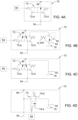
Fig.4a enthält die Ventilvorrichtung 70 in einer ersten Ausführungsform ein 2/2-Wegeventil als eine Ventileinheit 72. Ausgehend von einer ersten Schaltstellung bzw. Ruhestellung 72-0 ist eine zweite Schaltstellung 72-a durch eine geeignete Steuereinheit 84 aktivierbar. Im Durchflussweg zwischen dem Pumpenausgang 54 und dem Versorgungsanschluss 48 wirkt die Ruhestellung 72-0 als eine hydraulische Verbindung und die zweite Schaltstellung 72-a wirkt als eine hydraulische Unterbrechung. - In
Fig. 4b ist die Ventileinheit 72 der Ventilvorrichtung 70 als ein 3/2-Wegeventil ausgebildet, wobei sie an der dem Pumpenausgang 54 abgewandten Anschlussseite zwei Ventilanschlüsse aufweist derart, dass bei aktivierter zweiter Schaltstellung 72-a der Pumpenausgang 54 abhängig vom Erreichen oder Überschreiten eines vorbestimmten Soll-Drucks p_soll als Ausgangsdruck p_a mit einem Tankanschluss 92 hydraulisch verbindbar ist. Hierzu wird ein Druckentlastungsventil 90 eingesetzt, dessen Rückstellfeder auf den Soll-Druck p_soll dimensioniert ist. - Bei der Ventileinheit 72 gemäß
Fig. 4c ist der Pumpenausgang 54 in der zweiten Schaltstellung 72-a permanent mit dem Tankanschluss 92 hydraulisch verbunden. - Die Ventilvorrichtung 70 gemäß
Fig. 4d enthält keine Ventileinheit 72 als Verbindung und Unterbrechung im Durchflussweg zwischen dem Pumpenausgang 54 und dem Versorgungsanschluss 48. Vielmehr enthält sie eine am vorgenannten Durchflussweg hydraulisch angeschlossene Ventileinheit 74 als einen hydraulischen Abzweig zu einem Tankanschluss 92. Die Ventileinheit 74 hat zwei Schaltstellungen 74-0, 74-a, welche durch die Steuereinheit 84 aktivierbar sind. - Die Ventilvorrichtung 70 gemäß
Fig. 4e enthält eine Kombination aus einer Ventileinheit 72 im Durchflussweg zwischen dem Pumpenausgang 54 und dem Versorgungsanschluss 48 und aus einer an diesem Durchflussweg hydraulisch angeschlossenen Ventileinheit 78 als einen hydraulischen Abzweig zu einem Tankanschluss 92. Die Ventileinheit 78 weist ein Druckentlastungsventil mit einer einstellbaren Rückstellfeder auf. Die Rückstellfeder wird je nach erforderlichem Arbeitsmodus der hydraulischen Anordnung 42 mittels der Steuereinheit 84 auf einen veränderbaren Soll-Druck eingestellt, insbesondere auf einen niedrigen Wert p_lo (z.B. 5 bis 10 bar) oder auf einen hohen Wert p_hi (z.B. 235 bar) eingestellt. In der inFig. 4e dargestellten ersten Schaltstellung der Ventileinheit 78 wirkt diese als eine hydraulische Unterbrechung zum Tankanschluss 92. Sobald der eingestellte Soll-Druck durch den Ausgangsdruck p_a am Pumpenausgang 54 erreicht oder überschritten worden ist, stellt sich an der Ventileinheit 78 eine zweite Schaltstellung ein, in der die Ventileinheit 78 als eine hydraulische Verbindung zum Tankanschluss 92 wirksam ist. - Die Ventilvorrichtung 70 gemäß
Fig. 4f enthält die vorgenannte Ventileinheit 78 und keine Ventileinheit 72. -
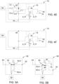
Fig. 5a zeigt die Ventilvorrichtung 80 im Durchflussweg zwischen dem Rückmeldeanschluss 50 und der Verstellsteuerung 64. Dabei wirkt die als ein 2/2-Wegeventil ausgebildete und von der Steuereinheit 84 ansteuerbare Ventileinheit 82 je nach ihrer Schaltstellung 82-0 (erste Schaltstellung) oder 82-a (zweite Schaltstellung) als eine hydraulische Verbindung oder Unterbrechung im Durchflussweg. - In
Fig. 5b ist die Ventileinheit 82 insoweit abgeändert, als sie dort als ein 3/2-Wegeventil ausgebildet ist mit zwei Ventilanschlüssen an der der Verstellsteuerung 64 abgewandten Anschlussseite. Dabei ist in der zweiten Schaltstellung 82-a die Verstellsteuerung 64 mit dem Tankanschluss 92 hydraulisch verbunden. - Mittels der beschriebenen hydraulischen Logik kann die Startphase des Antriebsmotors 22 mit besonders niedrigen Energieverlusten unterstützt werden, was insbesondere bei einem Kaltstart technische Vorteile bedeutet.
- Vor einem Start des Nutzfahrzeugs 10 ist die Verstellsteuerung 64, insbesondere deren Verstellzylinder, aufgrund der Druckverhältnisse üblicherweise auf eine Förderposition für eine maximale Fördermenge eingestellt. Das Ziel ist es, in der Startphase des Nutzfahrzeugs 10 die Leistungsaufnahme der Verstellpumpe 46 möglichst klein zu halten und hierbei optional auch die Verstellsteuerung 64, insbesondere deren Verstellzylinder, auf eine Förderposition für eine minimale Fördermenge einzustellen. Dieses Ziel wird mit den hydraulischen Anordnungen 42 gemäß
Fig. 2 und Fig. 3 erreicht. - Ausgehend von den Ruhestellungen bzw. ersten Schaltstellungen 72-0, 74-0, 82-0 der Ventileinheiten 72, 74, 82 und/oder einem eingestellten hohen Soll-Druck p_hi an der Ventileinheit 78 wird ein beabsichtigter Start des Antriebsmotors 22 von der Steuereinheit 84 (z.B. über empfangene Bussignale eines Fahrzeug-Busses, wie etwa ISO, CAN) detektiert, welche daraufhin die zweite Schaltstellung 72-a, 74-a, 82-a aktiviert und/oder den niedrigen Soll-Druck p_lo an der Ventileinheit 78 einstellt. Danach kann der Antriebsmotor 22 gestartet werden. Nach durchgeführtem Startvorgang kann die Steuereinheit 84 die Ventileinheiten 72, 74, 82 wieder in ihre erste Schaltstellung 72-0, 74-0, 82-0 überführen und/oder an der Ventileinheit 78 den eingestellten niedrigen Soll-Druck p_lo wieder verändern, indem sie den hohen Soll-Druck p_hi einstellt.
- Während und unmittelbar nach dem Start des Antriebsmotors 22 steigt der Ausgangsdruck p_a der Verstellpumpe 46 bei der Variante gemäß
Fig. 4a lediglich bis zu einem Bereitschaftsdruck an, während die Verstellsteuerung 64 die Förderposition in Richtung minimaler Fördermenge verstellt. - Während die Pumpenverstellung in Richtung der minimalen Förderposition verstellt wird, könnte der Ausgangsdruck p_a weiter ansteigen. Um diese unerwünschte Pumpenleistung zu vermeiden, kann bei der Variante gemäß
Fig. 4b der Soll-Druck p_soll derart eingestellt werden, dass er einem Ausgangsdruck p_a entspricht, welcher ausreichend groß ist, um die Verstellsteuerung 64 in Richtung minimaler Förderposition zu steuern. - Bei der Variante gemäß
Fig. 4c verbleibt in der zweiten Schaltstellung 72-a zwar die Verstellsteuerung 64 in ihrer maximalen Förderposition, aber die Verstellpumpe 46 benötigt nur eine geringe Antriebsleistung, da der Ausgangsdruck p_a etwa einem sehr niedrigen Tankdruck entspricht. - Der vorgenannte sehr niedrige Tankdruck am Pumpenausgang 54 kann auch bei der Variante gemäß
Fig. 4d erzielt werden. - Auch bei der Variante gemäß
Fig. 4e benötigt die Verstellpumpe 46 in der zweiten Schaltstellung nur eine geringe Antriebsleistung, da der Ausgangsdruck p_a etwa einem sehr niedrigen Tankdruck entspricht. Die geringe Antriebsleistung für die Verstellpumpe 46 wird unterstützt, indem an der Ventileinheit 78 der sehr niedrige Soll-Druck p_lo eingestellt ist. - Der vorgenannte sehr niedrige Tankdruck an der Verstellpumpe 46 kann auch mit der Variante gemäß
Fig. 4f erzielt werden. - Bei den Varianten gemäß
Fig. 5a und Fig. 5b wird in der zweiten Schaltstellung 82-a keine Last sensiert, so dass die Verstellsteuerung 64 in Richtung der minimalen Förderposition beeinflusst werden kann. Außerdem ist es möglich, dass der Ausgangsdruck p_a der Verstellpumpe 46 lediglich bis zu einem Bereitschaftsdruck ansteigt.
Claims (14)
- Hydraulische Anordnung (42) für ein Nutzfahrzeug (10),- mit einem an einen Pumpenausgang (54) einer hydraulischen Verstellpumpe (46) hydraulisch angeschlossenen oder anschließbaren Versorgungsanschluss (48) als Schnittstelle zur Versorgung hydraulischer Verbraucher (58) des Nutzfahrzeugs (10),- mit einem Rückmeldeanschluss (50) als Schnittstelle für eine Druckrückmeldung von Verbrauchern (58),- mit einer von einem Ausgangsdruck (p_a) der Verstellpumpe (46) und von einem Meldedruck (p_m) des Rückmeldeanschlusses (50) abhängigen Verstellsteuerung (64) zur Verstellung der Verstellpumpe (46), und- mit einer hydraulischen Ventilvorrichtung (80) im Durchflussweg zwischen dem Rückmeldeanschluss (50) und der Verstellsteuerung (64), wobei die Ventilvorrichtung (80) eine Ventileinheit (82) enthält mit einer als hydraulische Verbindung im Durchflussweg wirksamen ersten Schaltstellung (82-0) und mit einer als hydraulische Unterbrechung im Durchflussweg wirksamen zweiten Schaltstellung (82-a).
- Hydraulische Anordnung nach Anspruch 1, dadurch gekennzeichnet, dass die im Durchflussweg zwischen dem Rückmeldeanschluss (50) und der Verstellsteuerung (64) angeordnete Ventileinheit (82) zumindest an der der Verstellsteuerung (64) zugewandten Anschlussseite einen einzigen Ventilanschluss aufweist.
- Hydraulische Anordnung nach Anspruch 1 oder 2, dadurch gekennzeichnet, dass die Ventileinheit (82) an der der Verstellsteuerung (64) abgewandten Anschlussseite zwei Ventilanschlüsse aufweist derart, dass in der zweiten Schaltstellung (82-a) die Verstellsteuerung (64) mit einem Tankanschluss (92) hydraulisch verbunden ist.
- Hydraulische Anordnung nach einem der vorhergehenden Ansprüche, gekennzeichnet durch eine hydraulische Ventilvorrichtung (70) im Durchflussweg zwischen dem Pumpenausgang (54) und dem Versorgungsanschluss (48), wobei die Ventilvorrichtung (70)- eine Ventileinheit (72) enthält mit einer als hydraulische Verbindung im Durchflussweg wirksamen ersten Schaltstellung (72-0) und mit einer als hydraulische Unterbrechung im Durchflussweg wirksamen zweiten Schaltstellung (72-a), und/oder- eine am Durchflussweg hydraulisch angeschlossene Ventileinheit (74, 78) als Abzweig zu einem Tankanschluss (92) enthält mit einer als hydraulische Unterbrechung zum Tankanschluss (92) wirksamen ersten Schaltstellung (74-0) und mit einer als hydraulische Verbindung zum Tankanschluss (92) wirksamen zweiten Schaltstellung (74-a).
- Hydraulische Anordnung nach Anspruch 4, dadurch gekennzeichnet, dass in der zweiten Schaltstellung (72-a) der im Durchflussweg zwischen dem Pumpenausgang (54) der Verstellpumpe (46) und dem Versorgungsanschluss (48) angeordneten Ventileinheit (72) der Pumpenausgang (54) mit einem Tankanschluss (92) hydraulisch verbindbar ist oder hydraulisch verbunden ist.
- Hydraulische Anordnung nach Anspruch 5, dadurch gekennzeichnet, dass der Pumpenausgang (54) abhängig vom Erreichen oder Überschreiten eines vorbestimmten Soll-Drucks (p_soll) am Pumpenausgang (54) mit dem Tankanschluss (92) hydraulisch verbindbar ist.
- Hydraulische Anordnung nach einem der Ansprüche 4 bis 6, dadurch gekennzeichnet, dass die im Durchflussweg zwischen dem Pumpenausgang (54) der Verstellpumpe (46) und dem Versorgungsanschluss (48) angeordnete Ventileinheit (72) zumindest an der dem Pumpenausgang (54) zugewandten Anschlussseite einen einzigen Ventilanschluss aufweist.
- Hydraulische Anordnung nach einem der Ansprüche 4 bis 7, dadurch gekennzeichnet, dass die im Durchflussweg zwischen dem Pumpenausgang (54) der Verstellpumpe (46) und dem Versorgungsanschluss (48) angeordnete Ventileinheit (72) an der dem Pumpenausgang (54) abgewandten Anschlussseite zwei Ventilanschlüsse aufweist.
- Hydraulische Anordnung nach einem der Ansprüche 4 bis 8, dadurch gekennzeichnet, dass die am Durchflussweg abzweigende Ventileinheit (74) als ein 2/2-Wegeventil ausgebildet ist.
- Hydraulische Anordnung nach einem der Ansprüche 4 bis 9, dadurch gekennzeichnet, dass die am Durchflussweg abzweigende Ventileinheit (78) ihre als hydraulische Verbindung zum Tankanschluss (92) wirksame zweite Schaltstellung in Abhängigkeit vom Erreichen oder Überschreiten eines vorbestimmten Soll-Drucks (p_lo) am Pumpenausgang (54) einnimmt.
- Hydraulische Anordnung nach Anspruch 10, dadurch gekennzeichnet, dass der Soll-Druck (p_lo, p_hi) an der abzweigenden Ventileinheit (78) veränderlich einstellbar ist.
- Nutzfahrzeug (10) mit einem Antriebsmotor (22) und mit einer hydraulischen Anordnung (42) nach einem der Ansprüche 1 bis 11.
- Nutzfahrzeug nach Anspruch 12, dadurch gekennzeichnet, dass der Antriebsmotor (22) mit der Verstellpumpe (46) antriebsverbunden ist.
- Nutzfahrzeug nach Anspruch 12 oder 13, dadurch gekennzeichnet, dass sich die Ventileinheit (72, 74, 78, 82) unmittelbar vor einem Start und/oder während eines Starts des Antriebsmotors (22) in ihrer zweiten Schaltstellung (72-a, 74-a, 82-a) befindet.
Applications Claiming Priority (1)
| Application Number | Priority Date | Filing Date | Title |
|---|---|---|---|
| DE102023129650.7A DE102023129650A1 (de) | 2023-10-27 | 2023-10-27 | Hydraulische Anordnung und Nutzfahrzeug |
Publications (1)
| Publication Number | Publication Date |
|---|---|
| EP4545804A1 true EP4545804A1 (de) | 2025-04-30 |
Family
ID=92538731
Family Applications (1)
| Application Number | Title | Priority Date | Filing Date |
|---|---|---|---|
| EP24196178.8A Pending EP4545804A1 (de) | 2023-10-27 | 2024-08-23 | Hydraulische anordnung und nutzfahrzeug |
Country Status (3)
| Country | Link |
|---|---|
| US (1) | US20250137469A1 (de) |
| EP (1) | EP4545804A1 (de) |
| DE (1) | DE102023129650A1 (de) |
Citations (3)
| Publication number | Priority date | Publication date | Assignee | Title |
|---|---|---|---|---|
| DE102010006858A1 (de) * | 2010-02-04 | 2011-08-04 | Daimler AG, 70327 | Ventilsystem für ein Hydrauliksystem eines Kraftfahrzeuges |
| US20160230787A1 (en) * | 2013-09-18 | 2016-08-11 | Alfred-Kärcher GmbH & Co. KG | Implement carrier with improved control of hydraulic fluid supply |
| US11378104B1 (en) * | 2021-07-28 | 2022-07-05 | Deere & Company | Flow management of a hydraulic system |
Family Cites Families (3)
| Publication number | Priority date | Publication date | Assignee | Title |
|---|---|---|---|---|
| DE102013005213A1 (de) * | 2013-03-27 | 2014-10-02 | Claas Industrietechnik Gmbh | Fahrzeug mit Anbaugerätekupplung und Anbaugerät dafür |
| CN108026713B (zh) * | 2015-09-16 | 2021-03-09 | 卡特彼勒Sarl | 液压作业机器的液压泵控制系统 |
| US11378102B1 (en) * | 2021-07-28 | 2022-07-05 | Deere & Company | Flow management of a hydraulic system |
-
2023
- 2023-10-27 DE DE102023129650.7A patent/DE102023129650A1/de active Pending
-
2024
- 2024-08-23 EP EP24196178.8A patent/EP4545804A1/de active Pending
- 2024-09-09 US US18/828,228 patent/US20250137469A1/en active Pending
Patent Citations (3)
| Publication number | Priority date | Publication date | Assignee | Title |
|---|---|---|---|---|
| DE102010006858A1 (de) * | 2010-02-04 | 2011-08-04 | Daimler AG, 70327 | Ventilsystem für ein Hydrauliksystem eines Kraftfahrzeuges |
| US20160230787A1 (en) * | 2013-09-18 | 2016-08-11 | Alfred-Kärcher GmbH & Co. KG | Implement carrier with improved control of hydraulic fluid supply |
| US11378104B1 (en) * | 2021-07-28 | 2022-07-05 | Deere & Company | Flow management of a hydraulic system |
Also Published As
| Publication number | Publication date |
|---|---|
| US20250137469A1 (en) | 2025-05-01 |
| DE102023129650A1 (de) | 2025-04-30 |
Similar Documents
| Publication | Publication Date | Title |
|---|---|---|
| EP3896312B1 (de) | Hydraulische anordnung für ein fahrzeuggetriebe | |
| EP2613058A2 (de) | Hydrauliksystem | |
| EP3012463B1 (de) | Hydraulikaggregat | |
| DE3120937A1 (de) | Hydraulische logikschaltung fuer eine pumpe mit einstellbarer foerdermenge | |
| DE10003748A1 (de) | Kraftstoffversorgungssystem für Brennkraftmaschinen mit verbesserter Befüllung der Kraftstoffleitung | |
| EP2161458B1 (de) | Anordnung zur Versorgung eines Hydrauliksystems mit Hydraulikflüssigkeit | |
| EP3398418A1 (de) | Hydrauliksystem einer land- oder bauwirtschaftlich nutzbaren arbeitsmaschine | |
| EP2049800A1 (de) | Förderpumpe | |
| DE3247289A1 (de) | Einrichtung zum speichern hydraulischer energie | |
| EP2280197B1 (de) | Hydrostatischer Mehrmotorenantrieb | |
| EP4545803A1 (de) | Hydraulische anordnung und nutzfahrzeug | |
| DE102023129650A1 (de) | Hydraulische Anordnung und Nutzfahrzeug | |
| DE10335698A1 (de) | Kraftstoffversorgungsanlage einer Brennkraftmaschine sowie Betriebsverfahren hierfür | |
| WO2004024536A1 (de) | Lenkhelfvorrichtung für ein fahrzeug | |
| DE102006039698B3 (de) | Förderpumpe | |
| EP3461707A1 (de) | Steuersystem einer hydraulisch betätigten bremseinrichtung | |
| DE2446008A1 (de) | Hydrostatisches antriebssystem | |
| DE102023124711A1 (de) | Hydraulische Anordnung und Nutzfahrzeug | |
| EP4524403A1 (de) | Hydraulische anordnung und nutzfahrzeug | |
| EP1923606A2 (de) | Hydraulische Anordnung | |
| EP3798037A1 (de) | Zapfwellensystem und landwirtschaftliches fahrzeug | |
| DE19823776C2 (de) | Hydraulikanlage für ein Schiff | |
| AT526441B1 (de) | Ölversorgungsvorrichtung | |
| DE202006015508U1 (de) | Förderpumpe | |
| EP0915010A2 (de) | Hydraulikanlage für ein Schiff |
Legal Events
| Date | Code | Title | Description |
|---|---|---|---|
| PUAI | Public reference made under article 153(3) epc to a published international application that has entered the european phase |
Free format text: ORIGINAL CODE: 0009012 |
|
| STAA | Information on the status of an ep patent application or granted ep patent |
Free format text: STATUS: THE APPLICATION HAS BEEN PUBLISHED |
|
| AK | Designated contracting states |
Kind code of ref document: A1 Designated state(s): AL AT BE BG CH CY CZ DE DK EE ES FI FR GB GR HR HU IE IS IT LI LT LU LV MC ME MK MT NL NO PL PT RO RS SE SI SK SM TR |
|
| STAA | Information on the status of an ep patent application or granted ep patent |
Free format text: STATUS: REQUEST FOR EXAMINATION WAS MADE |
|
| 17P | Request for examination filed |
Effective date: 20251030 |