EP4545792A1 - Temperierpumpe mit einem strukturierten rotorkern - Google Patents
Temperierpumpe mit einem strukturierten rotorkern Download PDFInfo
- Publication number
- EP4545792A1 EP4545792A1 EP24204770.2A EP24204770A EP4545792A1 EP 4545792 A1 EP4545792 A1 EP 4545792A1 EP 24204770 A EP24204770 A EP 24204770A EP 4545792 A1 EP4545792 A1 EP 4545792A1
- Authority
- EP
- European Patent Office
- Prior art keywords
- rotor
- rotor core
- holes
- grooves
- pump
- Prior art date
- Legal status (The legal status is an assumption and is not a legal conclusion. Google has not performed a legal analysis and makes no representation as to the accuracy of the status listed.)
- Withdrawn
Links
Images


Classifications
-
- F—MECHANICAL ENGINEERING; LIGHTING; HEATING; WEAPONS; BLASTING
- F04—POSITIVE - DISPLACEMENT MACHINES FOR LIQUIDS; PUMPS FOR LIQUIDS OR ELASTIC FLUIDS
- F04D—NON-POSITIVE-DISPLACEMENT PUMPS
- F04D13/00—Pumping installations or systems
- F04D13/02—Units comprising pumps and their driving means
- F04D13/06—Units comprising pumps and their driving means the pump being electrically driven
- F04D13/0606—Canned motor pumps
-
- F—MECHANICAL ENGINEERING; LIGHTING; HEATING; WEAPONS; BLASTING
- F04—POSITIVE - DISPLACEMENT MACHINES FOR LIQUIDS; PUMPS FOR LIQUIDS OR ELASTIC FLUIDS
- F04D—NON-POSITIVE-DISPLACEMENT PUMPS
- F04D13/00—Pumping installations or systems
- F04D13/02—Units comprising pumps and their driving means
- F04D13/06—Units comprising pumps and their driving means the pump being electrically driven
- F04D13/0606—Canned motor pumps
- F04D13/064—Details of the magnetic circuit
-
- B—PERFORMING OPERATIONS; TRANSPORTING
- B60—VEHICLES IN GENERAL
- B60H—ARRANGEMENTS OF HEATING, COOLING, VENTILATING OR OTHER AIR-TREATING DEVICES SPECIALLY ADAPTED FOR PASSENGER OR GOODS SPACES OF VEHICLES
- B60H1/00—Heating, cooling or ventilating devices
- B60H1/32—Cooling devices
- B60H1/3204—Cooling devices using compression
- B60H1/3226—Self-contained devices, i.e. including own drive motor
-
- B—PERFORMING OPERATIONS; TRANSPORTING
- B60—VEHICLES IN GENERAL
- B60L—PROPULSION OF ELECTRICALLY-PROPELLED VEHICLES; SUPPLYING ELECTRIC POWER FOR AUXILIARY EQUIPMENT OF ELECTRICALLY-PROPELLED VEHICLES; ELECTRODYNAMIC BRAKE SYSTEMS FOR VEHICLES IN GENERAL; MAGNETIC SUSPENSION OR LEVITATION FOR VEHICLES; MONITORING OPERATING VARIABLES OF ELECTRICALLY-PROPELLED VEHICLES; ELECTRIC SAFETY DEVICES FOR ELECTRICALLY-PROPELLED VEHICLES
- B60L58/00—Methods or circuit arrangements for monitoring or controlling batteries or fuel cells, specially adapted for electric vehicles
- B60L58/10—Methods or circuit arrangements for monitoring or controlling batteries or fuel cells, specially adapted for electric vehicles for monitoring or controlling batteries
- B60L58/24—Methods or circuit arrangements for monitoring or controlling batteries or fuel cells, specially adapted for electric vehicles for monitoring or controlling batteries for controlling the temperature of batteries
- B60L58/26—Methods or circuit arrangements for monitoring or controlling batteries or fuel cells, specially adapted for electric vehicles for monitoring or controlling batteries for controlling the temperature of batteries by cooling
-
- F—MECHANICAL ENGINEERING; LIGHTING; HEATING; WEAPONS; BLASTING
- F04—POSITIVE - DISPLACEMENT MACHINES FOR LIQUIDS; PUMPS FOR LIQUIDS OR ELASTIC FLUIDS
- F04D—NON-POSITIVE-DISPLACEMENT PUMPS
- F04D13/00—Pumping installations or systems
- F04D13/02—Units comprising pumps and their driving means
- F04D13/06—Units comprising pumps and their driving means the pump being electrically driven
-
- F—MECHANICAL ENGINEERING; LIGHTING; HEATING; WEAPONS; BLASTING
- F04—POSITIVE - DISPLACEMENT MACHINES FOR LIQUIDS; PUMPS FOR LIQUIDS OR ELASTIC FLUIDS
- F04D—NON-POSITIVE-DISPLACEMENT PUMPS
- F04D29/00—Details, component parts, or accessories
- F04D29/40—Casings; Connections of working fluid
- F04D29/42—Casings; Connections of working fluid for radial or helico-centrifugal pumps
- F04D29/426—Casings; Connections of working fluid for radial or helico-centrifugal pumps especially adapted for liquid pumps
-
- F—MECHANICAL ENGINEERING; LIGHTING; HEATING; WEAPONS; BLASTING
- F04—POSITIVE - DISPLACEMENT MACHINES FOR LIQUIDS; PUMPS FOR LIQUIDS OR ELASTIC FLUIDS
- F04D—NON-POSITIVE-DISPLACEMENT PUMPS
- F04D29/00—Details, component parts, or accessories
- F04D29/58—Cooling; Heating; Diminishing heat transfer
- F04D29/5806—Cooling the drive system
-
- F—MECHANICAL ENGINEERING; LIGHTING; HEATING; WEAPONS; BLASTING
- F04—POSITIVE - DISPLACEMENT MACHINES FOR LIQUIDS; PUMPS FOR LIQUIDS OR ELASTIC FLUIDS
- F04D—NON-POSITIVE-DISPLACEMENT PUMPS
- F04D29/00—Details, component parts, or accessories
- F04D29/58—Cooling; Heating; Diminishing heat transfer
- F04D29/586—Cooling; Heating; Diminishing heat transfer specially adapted for liquid pumps
-
- H—ELECTRICITY
- H02—GENERATION; CONVERSION OR DISTRIBUTION OF ELECTRIC POWER
- H02K—DYNAMO-ELECTRIC MACHINES
- H02K1/00—Details of the magnetic circuit
- H02K1/06—Details of the magnetic circuit characterised by the shape, form or construction
- H02K1/22—Rotating parts of the magnetic circuit
- H02K1/27—Rotor cores with permanent magnets
-
- H—ELECTRICITY
- H02—GENERATION; CONVERSION OR DISTRIBUTION OF ELECTRIC POWER
- H02K—DYNAMO-ELECTRIC MACHINES
- H02K1/00—Details of the magnetic circuit
- H02K1/06—Details of the magnetic circuit characterised by the shape, form or construction
- H02K1/22—Rotating parts of the magnetic circuit
- H02K1/27—Rotor cores with permanent magnets
- H02K1/2706—Inner rotors
- H02K1/272—Inner rotors the magnetisation axis of the magnets being perpendicular to the rotor axis
- H02K1/274—Inner rotors the magnetisation axis of the magnets being perpendicular to the rotor axis the rotor consisting of two or more circumferentially positioned magnets
- H02K1/2753—Inner rotors the magnetisation axis of the magnets being perpendicular to the rotor axis the rotor consisting of two or more circumferentially positioned magnets the rotor consisting of magnets or groups of magnets arranged with alternating polarity
- H02K1/278—Surface mounted magnets; Inset magnets
-
- H—ELECTRICITY
- H02—GENERATION; CONVERSION OR DISTRIBUTION OF ELECTRIC POWER
- H02K—DYNAMO-ELECTRIC MACHINES
- H02K1/00—Details of the magnetic circuit
- H02K1/06—Details of the magnetic circuit characterised by the shape, form or construction
- H02K1/22—Rotating parts of the magnetic circuit
- H02K1/28—Means for mounting or fastening rotating magnetic parts on to, or to, the rotor structures
-
- H—ELECTRICITY
- H02—GENERATION; CONVERSION OR DISTRIBUTION OF ELECTRIC POWER
- H02K—DYNAMO-ELECTRIC MACHINES
- H02K7/00—Arrangements for handling mechanical energy structurally associated with dynamo-electric machines, e.g. structural association with mechanical driving motors or auxiliary dynamo-electric machines
- H02K7/14—Structural association with mechanical loads, e.g. with hand-held machine tools or fans
-
- F—MECHANICAL ENGINEERING; LIGHTING; HEATING; WEAPONS; BLASTING
- F05—INDEXING SCHEMES RELATING TO ENGINES OR PUMPS IN VARIOUS SUBCLASSES OF CLASSES F01-F04
- F05D—INDEXING SCHEME FOR ASPECTS RELATING TO NON-POSITIVE-DISPLACEMENT MACHINES OR ENGINES, GAS-TURBINES OR JET-PROPULSION PLANTS
- F05D2260/00—Function
- F05D2260/20—Heat transfer, e.g. cooling
-
- H—ELECTRICITY
- H01—ELECTRIC ELEMENTS
- H01M—PROCESSES OR MEANS, e.g. BATTERIES, FOR THE DIRECT CONVERSION OF CHEMICAL ENERGY INTO ELECTRICAL ENERGY
- H01M10/00—Secondary cells; Manufacture thereof
- H01M10/60—Heating or cooling; Temperature control
- H01M10/62—Heating or cooling; Temperature control specially adapted for specific applications
- H01M10/625—Vehicles
-
- H—ELECTRICITY
- H01—ELECTRIC ELEMENTS
- H01M—PROCESSES OR MEANS, e.g. BATTERIES, FOR THE DIRECT CONVERSION OF CHEMICAL ENERGY INTO ELECTRICAL ENERGY
- H01M10/00—Secondary cells; Manufacture thereof
- H01M10/60—Heating or cooling; Temperature control
- H01M10/65—Means for temperature control structurally associated with the cells
- H01M10/656—Means for temperature control structurally associated with the cells characterised by the type of heat-exchange fluid
-
- H—ELECTRICITY
- H02—GENERATION; CONVERSION OR DISTRIBUTION OF ELECTRIC POWER
- H02K—DYNAMO-ELECTRIC MACHINES
- H02K2213/00—Specific aspects, not otherwise provided for and not covered by codes H02K2201/00 - H02K2211/00
- H02K2213/03—Machines characterised by numerical values, ranges, mathematical expressions or similar information
Definitions
- the invention relates to a pump for driving a fluid, preferably a temperature control medium, in particular for use in a vehicle, very particularly for use for temperature control of a drive battery of an electric vehicle, wherein the pump comprises a stator and a rotor, wherein the rotor has a rotor body and a rotor block and is mounted rotatably about a rotation axis, wherein the rotor block comprises a metallic rotor core and magnets, wherein the rotor core comprises a plurality of holes in a cross section.
- the pump comprises a stator and a rotor, the rotor in turn comprising a rotor body, two rotary bearings, and a rotor block.
- the rotor block has a rotor core made of stacked electrical sheets and magnets attached to a radial outer side of the rotor core.
- the electrical sheets have a plurality of holes, which serve, on the one hand, to reduce the weight of the rotor core or block or the rotor, and, on the other hand, to guide the magnetic field lines in the rotor core.
- the energy and mobility transition requires the development of new technologies, particularly electric vehicles with a drive battery and an electric motor.
- Drive batteries achieve their greatest efficiency at temperatures around 20°C, so they must be heated or cooled depending on the situation. Heating is particularly useful shortly after starting in winter, while cooling is especially important after the vehicle has been in operation for some time.
- the thermal management of the drive train differs in electric vehicles from Combustion-engine vehicles, especially during the cold season.
- the entire component chain (pipes, quick connectors, pumps, battery housings, etc.) of the thermal management system in electric vehicles must also be designed to operate during the cold season and thus without the assistance of airflow.
- the invention is therefore based on the object of making the pumps for thermal management more efficient.
- the invention is preferably based on the object of increasing performance without increasing manufacturing costs or material usage.
- a pump for driving a fluid preferably a temperature control medium, in particular for use in a vehicle, very particularly for use for temperature control of a drive battery of an electric vehicle
- the pump comprises a stator and a rotor
- the rotor has a rotor body and a rotor block and is mounted so as to be rotatable about a rotation axis
- the rotor block comprises a metallic rotor core and magnets
- the rotor core comprises a plurality of holes in a cross section
- the rotor core has a plurality of grooves and a plurality of projections on its radial inner wall in a cross section.
- the invention is based on the finding that the rotor, and in particular the rotor core, can be further improved to increase the pump's performance. It was found that Magnetic field lines tend to leave the intended, radially outer regions of the rotor core in certain rotational positions of the rotor relative to the stator. The magnetic field lines can then extend within the rotor core, sometimes between a radial inner side of the holes and a radial inner side of the rotor core. The scattering of the magnetic field lines increases the magnetic resistance and reduces motor efficiency. Leakage fluxes are particularly pronounced in electric pumps, as the distance between the stator and the rotor block is relatively large due to the partition wall, the block housing, and the annular gap provided for the secondary current, which intensifies the leakage fluxes.
- the rotational axis A defines an axial, a radial, and/or a tangential or circumferential direction.
- the expression “radially inward” means the radial direction toward the rotational axis A.
- the term “axially inward” means the axial direction corresponding to the direction of the fluid flowing in the inlet.
- “axially inward” means an axial direction from the pump wheel toward the rotor block.
- the axially outermost section of the pump is preferably also the uppermost section of the pump.
- the end of the pump axially opposite the uppermost section is the lowermost section or the lower end.
- the Tangential directions are either clockwise or counterclockwise. The rotor rotates preferentially clockwise.
- the magnets are preferably permanent magnets.
- the rotor or rotor block preferably comprises at least six or eight magnets in a cross-section.
- the rotor or rotor block advantageously comprises a maximum of 20, 16 or 14 magnets in cross-section.
- the rotor core is advantageously circular-arc-shaped at least in sections along its circumference.
- the rotor core preferably comprises magnet locations on its radial outer side for arranging one magnet at a time. It is very preferred that the magnets are circular-arc-shaped on their radial inner side and/or on their radial outer side when viewed in plan view or in cross section. It is advantageous that the magnet locations have a circular-arc-shaped contour in plan view or in cross-section and in particular have a surface complementary to the magnets.
- the rotor core has a plurality of laminations, in particular rotor laminations, stacked one above the other.
- the rotor laminations are preferably electrical laminations.
- the rotor core comprises at least 10, 15, or 20 laminations or rotor laminations.
- the rotor core has a maximum of 50, 40, or 30 rotor laminations.
- a plurality of laminations or rotor laminations are aligned over a complete revolution.
- the laminations/rotor laminations can be connected to one another to form the rotor core by means of stamping or baking varnish. It is advantageous that the rotor laminations are provided with an insulating coating.
- the pump is designed so that the fluid in pump operation enters the block housing of the The fluid flows around the rotor body. This allows a secondary flow from the wheel chamber or a wheel chamber into the drive chamber. The secondary flow of fluid can then flow through the rotor in an axially outward direction back into the wheel chamber via return channels or a return channel. The secondary flow thereby carries away the heat from the stator, the rotor, and/or a circuit board, thereby cooling the pump and allowing it to operate more efficiently overall.
- the rotor body or the block housing comprises a plastic.
- the rotor body or the block housing is advantageously formed in one piece and preferably integrally. If the rotor body is manufactured integrally, for example by injection molding or overmolding, then the rotor body is lightweight yet very robust. This allows a large number of details to be implemented on the rotor body, of which return channels and blades are particularly noteworthy. As a result, the rotor body can be manufactured inexpensively, even though it contains a considerable number of technical details. At the same time, the rotor body, with an integral construction, is characterized by a correspondingly high level of robustness, which allows it to be constructed with relatively thin walls. The same applies analogously to the block housing.
- the rotor expediently comprises a pump impeller and/or a shaft.
- the pump impeller advantageously has a wheel plate and/or blades and/or a wheel cover.
- the wheel plate is expediently arranged axially inwardly relative to the blades.
- the blades preferably define blade channels between them. It is possible for the blades to be covered in the axially outward direction by a wheel cover.
- the wheel cover can be attached to the blades in particular by means of plugging or welding.
- the rotor body comprises the blades and/or the wheel disc and/or the shaft.
- the shaft advantageously has a drive section and/or a connecting section.
- the drive section and the block housing expediently overlap in the axial direction.
- the block housing, the drive section, the connecting section of the wheel discs and/or the blades are integrally connected to one another and preferably form the rotor body.
- the grooves alternate with the projections in a tangential direction. It is possible for the tangential extent of the grooves to correspond to that of the projections. It is preferred for the inner wall of the rotor core to be formed exclusively from the grooves and projections. This ensures that the largest possible areas of the radial inner wall contribute to guiding the field lines.
- the grooves and projections preferably extend along at least 50, 60, 70, 80, 90, or 100% of the axial extent of the rotor core or rotor block.
- the upper cover lamination, the lower cover lamination, the holder laminations, and/or the block laminations have the grooves and projections. This ensures that the largest possible areas of the radial inner wall contribute to guiding the field lines.
- the holes are offset in the tangential direction relative to the grooves.
- the holes and grooves alternate in the tangential direction. It is particularly preferred that the holes and grooves do not overlap in the tangential direction.
- at least one of the free spaces is associated with a groove in the tangential direction.
- at least one of the free spaces overlaps with the associated groove in the tangential direction.
- the at least one free space and its associated groove are axially symmetrical with respect to a common radius line. This enables the field lines to be guided or spatially limited radially inward, thereby keeping the magnetic field compact and the magnetic resistance low.
- the number of magnets in a cross-section of the rotor core corresponds to the number of holes, grooves, and/or projections. This results in the targeted influence of the magnetic field lines relative to each magnet. If each magnet is assigned a hole, each magnet can be supported in the same way in guiding the field lines through the hole. As a result, each magnet provides practically the same drive to the rotor, thereby achieving the smoothest possible running.
- At least one of the magnets, preferably each of the magnets, of the rotor block is assigned one of the holes and/or one of the projections - in particular in the tangential direction.
- the at least one magnet overlaps in the tangential direction with the assigned hole and/or with the assigned projection.
- the at least one magnet and/or the hole assigned to the magnet and/or the projection assigned to the magnet are axially symmetrical with respect to a common radius line. The axial symmetry causes the magnetic fields are always as similar as possible when passing through the rotor block or core, which allows for very smooth running.
- At least one of the holes and a projection associated with the at least one hole in the tangential direction overlap in the tangential direction. It is preferred that all of the holes overlap in the tangential direction with the respectively associated projection in the tangential direction.
- the at least one hole and the projection associated with the hole are axially symmetrical with respect to a common radius line. It is preferred that a tangential extension of the projection corresponds to at least 50, 60, 70, 80, or 90% of the tangential extension of the hole.
- a radial extension of a groove RN corresponds to a radial extension of a projection.
- a cross-sectional area of the projection formed by the radial extension of the projection and the tangential extension of the projection corresponds to at least 50, 60, 70, 80, or 90% of the cross-sectional area of the associated hole. This results in a relatively uniform distribution of the rotor core material throughout one revolution, thereby reducing electromagnetic or mechanical irregularities and increasing smooth running.
- two of the magnets and preferably all of the magnets of the rotor block in a cross-section of the rotor core have the same shape and/or the same magnetic properties and/or the same radial position.
- two of the holes and preferably all of the holes of the rotor core have the same shape and/or the same radial position.
- two of the projections and preferably all of the projections of the inner wall of the rotor core have the same shape and/or the same radial position.
- two of the grooves, and preferably all of the grooves in the inner wall of the rotor core have the same shape and/or the same radial position. This enables a uniform or repeating design of the rotor block in the tangential direction, thereby achieving extremely smooth running.
- a radial extent RL of the holes and a radial extent RKV of the rotor core at a circumferential position of a projection have a ratio RL/RKV of at most 0.80, 0.70, 0.60, 0.55, or 0.50. This causes the holes to be relatively flat in relation to the radial extent of the rotor core. This allows somewhat more space to be left for the field lines in a radially outer region of the rotor core, so that the field lines can be well confined in a radially outer region.
- an outer radius AR of the rotor core and a radial extent RKN of the rotor core at a circumferential position of a groove have a ratio AR/RKN of at least 2.0, 2.3, 2.5, 2.7, 3.0, or 3.2. This keeps the rotor core relatively thin or slender in the radial direction compared to the outer radius AR or diameter of the rotor core.
- the AR/RKN ratio can be larger the smaller the RL/RKV ratio.
- At least one of the grooves and/or at least one of the projections has a polygonal and preferably quadrangular shape.
- all grooves and/or all projections have a polygonal and preferably quadrangular shape. This tangentially relatively uniform shape evens out the radially acting effects of the grooves or projections in the tangential direction.
- a tangential extension of the at least one groove is at least a factor of 1.5, 2.0, or 2.5 greater than the radial Extension of the groove.
- the tangential extension of the at least one projection be at least 1.5, 2.0, or 2.5 times greater than the radial extension of the projection.
- the groove or projection is elongated in the tangential direction. This enables a sufficiently pronounced tangential effect relative to the radial effects of the projections or grooves.
- At least one of the holes, and preferably all of the holes, of the rotor core have a polygonal and in particular pentagonal shape in a cross-section of the rotor core.
- the at least one hole comprises a tip, which is preferably directed radially outwards. The tip serves primarily to cleanly separate the magnetic fields and thus to prevent stray flux.
- the at least one hole comprises a radial outer side.
- the tip of the hole represents the radially outermost point of the radial outer side of the hole.
- the at least one hole comprises two tangential outer sides.
- the at least one hole comprises a radial inner side. The radial inner side of the hole expediently connects the two tangential outer sides of the hole.
- the rotor core has an upper and/or a lower cover lamination.
- the upper and/or lower cover lamination preferably has no hole.
- the upper and/or lower cover lamination is/are advantageously designed such that no plastic flows into the holes in the rotor core during an overmolding process. This results in better guidance of the field lines.
- the holes advantageously extend over at least 50 or 60 or 70 or 80 or 90% of the axial extent of the rotor core or rotor block.
- At least one of the grooves has a radial extension RN, with the ratio RN/RKN preferably being at least 0.1, 0.14, or 0.17. This ensures that the magnetic field lines are sufficiently limited.
- the ratio RN/RKN is advantageously at most 0.60, 0.50, 0.40, 0.30, or 0.25. This ensures that the field lines are not excessively limited or deformed, thus preventing an increase in the magnetic resistance.
- a pump according to the invention advantageously comprises an inlet 8 and an outlet 9, shown in dashed lines due to the selected longitudinal section.
- the pump has a rotor 2, which advantageously comprises a pump wheel 6.
- the pump has a stator 1, which has a Rotor block 4 drives the rotor.
- the rotor block 4 is a component of the rotor 2.
- the rotor 2 expediently comprises a shaft 7, which transmits the torque of the rotor block 4 to the impeller 6.
- the impeller 6 preferably comprises blades 19 and/or a wheel plate 31.
- the blades 19 propel the fluid flowing in through the inlet 8 radially outward, where it is conveniently collected by a collecting channel 28 along almost its entire circumference.
- the collecting channel 28 conveniently opens into the outlet 9.
- the fluid flow from the inlet 8 via the impeller 6 into the collecting channel 28 to the outlet 9 is the main fluid flow.
- the chain of elements 8, 6, 28, 9 forms a main flow path.
- the pump preferably comprises a partition wall 16 and a housing 15. It is highly preferred that the partition wall 16 separates a space within the housing 15 into a dry area and a wet area.
- the stator 1 is preferably arranged in the dry area.
- the pump advantageously comprises a circuit board 18 for controlling pump operation and in particular for controlling the stator 1. It is preferred that the circuit board 18 is located in the dry area of the pump.
- the wet area of the pump preferably comprises the inlet 8 and the outlet 9. It is preferred that the wet area has a wheel chamber 10 within which the pump wheel 6 is arranged.
- a circumferential gap is located between the partition wall 16 and the wheel plate 31 or the pump wheel 6, through which the fluid can flow from the wheel chamber 10 into the drive chamber 11.
- the rotor 2 has at least one return channel 12 and preferably a plurality of return channels 12, which extend approximately axially within the rotor 2 and connect a lowermost region of the drive chamber 11 to the wheel chamber 10.
- the secondary flow Due to the pressure difference between the radial inside and radial outside generated by the impeller 6, a small portion of the fluid—the secondary flow—flows from the wheel chamber 10 into the drive chamber 11 and from there past the rotor block 4 to the lowest region of the drive chamber 11. The secondary flow then enters a lower inlet of the return channel 12(s), flows through the rotor 2, and finally exits at the top in a radially inner region of the wheel chamber 10. There, the secondary flow mixes with the main flow.
- the secondary current has the advantage of dissipating the heat from the stator 1, the rotor block 4, and the circuit board 18, allowing the pump to operate more efficiently overall.
- this also means that the rotor block 4 is located within a wet area, and corresponding technical requirements must be placed on the rotor block 4 and the rotor 2.
- the rotor 2 of this embodiment comprises a rotor body 3, which preferably comprises a plastic material.
- the rotor body 3 can comprise the blades 19, the wheel plate 31, the shaft 7, the return channels 12, and/or a block housing 17.
- the rotor body 3 is manufactured by injection molding or by overmolding the rotor block 4.
- the block housing 17 of this exemplary embodiment completely encloses the rotor block 4 with the magnets 13 and the rotor core 22. This ensures very good protection of the rotor block 4 from the secondary current.
- the overmolding makes it possible to create very smooth outer surfaces of the rotor 2 or the rotor body 3, so that the rotor 2 rotating in the fluid has good fluid dynamic properties.
- an axle 23 is mounted in a rotationally fixed manner in a base of the partition 16.
- the axle 23 defines an axis of rotation A around which the rotor 2 rotates.
- the rotor 2 can advantageously have a pivot bearing 5, which can be optimized from a tribological point of view and may in particular comprise graphite.
- the pump preferably comprises an axle holder 24, which in this exemplary embodiment is pressed into a receptacle of a spider. Consequently, an upper, axial end face of the pivot bearing 5 rotates relative to a lower, axial end face of the axle bearing 24.
- the rotor body 3 be produced by overmolding the pivot bearing 5 and the rotor block 4.
- the rotor 2 can have a rotor cover 25, which is preferably plugged onto the blades 19.
- a rotor cap can be arranged at a lower end of the motor 2, which is preferably only attached to the rotor 2 after overmolding.
- the rotor block 4 or rotor core 22 is shown in a simplified manner because there are no grooves (not shown) on a radial inner wall of the rotor core 22. These grooves 32 and projections 33 are, however, in the Figures 3 and 4 visible.
- the grooves 32 and projections 33 particularly preferably extend along the entire axial length of the rotor block 4 or the rotor core 22.
- the upper cover lamination 27a, the lower cover lamination 27b, the holder laminations 21 and/or the block laminations 20 have the grooves 32 and the projections 33.
- the magnets 13 are preferably arranged on a radial outer side of the rotor core 22, see.
- the rotor block 4 comprises magnet holders 14, which hold the magnets 13 to the rotor core 22. By holding the magnets 13 to the rotor core 22, the rotor block 4 is sufficiently stable overall for subsequent overmolding.
- the rotor core 22 of this exemplary embodiment consists of 25 stacked laminations 20, 21, 27.
- the laminations 20, 21, 27 are preferably electrical steel sheets.
- the electrical steel sheets are expediently provided with an insulating coating to prevent eddy currents—particularly in the axial direction.
- the laminations 20, 21, 27 of this initial example can be connected to one another by means of stamped stacking or by means of baked enamel to form the coherent rotor core 22.
- the rotor core 22 has exactly twenty-two block laminations 20 made of electrical steel sheets, each of which has the same shape.
- the rotor block 4 of this embodiment comprises a total of ten magnets 13, which are preferably designed as permanent magnets. For the sake of clarity, Figure 2 However, only five magnets 13 are shown. It is preferred that the magnets 13 are arranged on their radial
- the rotor core 22 is configured in a circular arc shape on its inner side and/or on its radial outer side in a plan view of the rotor block.
- the rotor core 22 advantageously has ten magnet locations 30 on its radial outer side, each magnet location 30 being assigned to a magnet 13.
- the magnet holders 14 or magnet locations 30 or magnets 13 are arranged equidistant from one another in the tangential direction.
- the lowermost lamella is designed as a lower cover lamella 27b.
- the lower cover lamella can comprise an electrical steel sheet or a plastic.
- the lower cover lamella 27b preferably comprises several, and in this exemplary embodiment, ten, axial holders 29. Each axial holder 29 is expediently assigned to a magnet location 30.
- the axial holders 29 are preferably designed as axial stops, so that the magnets 13 are securely held on the rotor core 22 in the axial direction downwards.
- the rotor core may have an upper cover lamella 27a, which is preferably designed as a block lamella 20. It is possible for the lower cover lamella 27b to be located above the upper cover lamella 27a after assembly of the pump, so that the directional convention of the lamellas can deviate from the above directional convention of the pump.
- the rotor core 22 comprises two holder laminations 21, or an upper holder lamination 21 and a lower holder lamination 21.
- the two holder laminations 21 of this exemplary embodiment preferably have a plurality of magnet holders 14, preferably each having a number corresponding to the number of magnets.
- the magnet holders 14 are an integral component of the holder lamination(s) 21.
- the magnet holders 14 or the holder lamination(s) 21 are produced by means of stamping.
- the holder lamination 21 is provided in an upper half, an upper third, or an upper quarter of the rotor core 22.
- the lower holder lamination 21 is expediently arranged in a lower half or in a lower third or in a lower quarter of the rotor core 22.
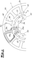
- FIG 3 a simplified top view of the rotor block 4 is shown because the upper cover lamella 27a has been omitted to reveal a top block lamella 20.
- the Figure 3 is opposite the Figure 2 also simplified in that the grooves on the radial outer wall of the rotor core 22 are missing.
- Figure 3 is opposite Figure 2 also simplified in that only one magnet holder 14 is shown.
- the rotor core 22 has grooves 32 and projections 33 on its radial inner wall 34.
- the grooves 32 expediently alternate with the projections 33 in a tangential direction.
- the tangential extent of the grooves 32 corresponds to that of the projections 33.
- the rotor core 22 is advantageously designed such that the grooves 32 and the projections 33 complement each other to form the inner wall 34 of the rotor core 22. It is preferred that the inner wall 34 of the rotor core 22 be formed exclusively from the grooves 32 and projections 33. It is possible for a tangential extent of one of the grooves 32 to correspond to a tangential extent of an adjacent projection 33.
- the rotor core 22 has holes 26.
- the block laminations and/or the holder laminations have the holes 26.
- the upper cover lamination 27a and/or the lower cover lamination 27b have no holes.
- the holes 26 are preferably filled with air. This is advantageously achieved via the upper cover lamination 27a and the lower cover lamination 27b, which both have no holes and the holes 26 of the other slats 20, 21. This prevents the holes 26 from being filled with plastic during an overmolding process.
- the holes 26 extend in the axial direction over at least 50, 60, 70, 80, or 90% of the axial extent of the magnets 13. It is advantageous that the grooves 32 extend over at least 50, 60, 70, 80, 90, or 95% of the axial extent of the magnets 13. It is highly preferred that the upper cover plate 27a and/or the lower cover plate 27b have the grooves 32 and the projections 33 on their radial inner side.
- the number of magnets 13 corresponds to the number of holes 26, grooves 32, and/or projections 33.
- at least one of the magnets 13, and preferably each of the magnets 13, is assigned one of the holes 26 and/or one of the projections 33—particularly in the tangential direction.
- the at least one magnet 13 preferably overlaps in the tangential direction with the associated hole 26 and/or with the associated projection 33.
- one hole 26 and one projection 33 each overlap in the tangential direction.
- the at least one magnet 13 and/or the hole 26 assigned to the magnet 13 and/or the projection 33 assigned to the magnet 13 are axially symmetrical with respect to a common radius line.
- the holes 26 are offset in the tangential direction relative to the grooves 32. It is highly preferred that the holes 26 and the grooves 32 alternate in the tangential direction. Particularly preferably, the holes 26 and the grooves 32 do not overlap in the tangential direction.
- the free spaces overlap in the tangential direction between the magnets 13. with the grooves 32 in the tangential direction. It is highly preferred that one of the free spaces between the magnets and a groove 32 overlapping this free space in the tangential direction are axially symmetrical with respect to a common radius.
- At least one hole 26 and preferably all of the holes 26 are polygonal, preferably at least triangular, and particularly preferably pentagonal.
- the at least one hole 26 preferably comprises a tip 26a, which advantageously faces radially outwards. It is very preferred that the at least one hole 26 comprises a radial outer side 26b.
- the tip 26a represents the radially outermost point of the radial outer side 26b.
- the radial outer side 26b is formed by two straight lines converging on one another, which advantageously each extend in a tangential and a radial direction.
- the at least one hole 26 comprises two tangential outer sides 26c.
- the at least one hole 26 comprises a radial inner side 26d.
- the radial inner side 26d expediently connects the two tangential outer sides 26c.
- the at least one hole 26, and preferably all holes 26, is/are preferably relatively flat. It is preferred that a tangential extension TL of the at least one hole 26 is greater than a radial extension RL of the hole 26.
- the rotor core 22 (K) has a radial (R) extension RKV at the location of a projection 33 (V). It is very preferred that a ratio RL/RKV is at most 0.70, 0.65, or 0.50. In this exemplary embodiment, the ratio RL/RKV may be approximately 0.40.
- the rotor core is advantageously designed to be relatively slim in the radial direction, particularly in the area of the slots 32.
- the rotor core 22 (K) has A slot 32 (N) has a radial (R) extension RKN.
- the rotor core 22 has an outer radius AR.
- the outer radius AR is preferably the arithmetically averaged value of all outer radii over a full revolution. It is very preferred that a ratio AR/RKN is at least 2.3, 2.7, or 3.0. In this exemplary embodiment, this ratio may be 3.5.
- a slot 32 (N) has a radial (R) extension RN.
- the ratio RN/RKN is preferably at least 0.1, 0.14, or 0.17, and in the exemplary embodiment, approximately 0.21.
- FIG 4 is a partial view of the rotor block 4 from Figure 3 shown, with the rotor block 4 opposite Figure 3 is additionally surrounded by a simplified stator 1.
- Figure 4 In particular, stator windings and the partition 16 have been omitted.
- the stator 1 shown here essentially corresponds to a cross-section of a stator core or a top view of a lamination of the stator core.
- Figure 4 the magnet holders 14 and the grooves on the radial outer side of the rotor core 22 are omitted.
- the stator 1 or stator core has a stator ring 35 and a plurality of inwardly projecting poles 36.
- the poles 36 expediently each comprise a pole core 37 and a pole shoe 38.
- the stator winding (not shown) is wound in particular in the tangential direction around the pole core 37 and is held in the radial direction by the pole shoe 38 and the stator ring 35.
- Figure 4 magnetic field lines 39a, 39b.
- the magnetic field lines 39a, 39b form a closed circuit over a first pole core 37, the stator ring 35, a second pole core 37, a first magnet 13, the rotor core 22 and a second magnet 13.
- line 39a symbolizes an outer field line
- line 39b represents an inner field line.
- the holes 26 - preferably filled with air - influence an expansion of the field lines 39a, 39b and in particular the outer field line 39a, so that the outer field line 39a runs along the radial outer side 26b and along the tangential outer side 26c of the holes 26.
- the outer field line 39a is also limited radially inward, in particular by the groove 32.
- the field lines 39a, 39b are concentrated on the smallest possible outer region within the rotor block 4 or rotor core 22, thereby achieving a correspondingly lower magnetic resistance.
- the holes 26 and the grooves 32 concentrate the magnetic field lines on a radially outer region of the rotor core 22 and also prevent stray fluxes. This is particularly advantageous for pumps with a partition and secondary current, because the distance between the stator 1 and rotor block 4 is greater and, consequently, the tendency toward field line divergence and stray fluxes is also greater.
Landscapes
- Engineering & Computer Science (AREA)
- Mechanical Engineering (AREA)
- Power Engineering (AREA)
- General Engineering & Computer Science (AREA)
- Physics & Mathematics (AREA)
- Thermal Sciences (AREA)
- Life Sciences & Earth Sciences (AREA)
- Sustainable Development (AREA)
- Sustainable Energy (AREA)
- Transportation (AREA)
- Iron Core Of Rotating Electric Machines (AREA)
- Connection Of Motors, Electrical Generators, Mechanical Devices, And The Like (AREA)
- Permanent Field Magnets Of Synchronous Machinery (AREA)
- Structures Of Non-Positive Displacement Pumps (AREA)
Abstract
Eine Pumpe umfasst einen Stator (1) und einen Rotor (2), wobei der Rotor (2) einen Rotorkörper (3) sowie einen Rotorblock (4) aufweist und um eine Rotationsachse (A) drehbar gelagert ist. Der Rotorblock (4) weist einen metallischen Rotorkern (22) und Magnete (13) auf. Der Rotorkern (22) weist in einem Querschnitt mehrere Löcher (26) auf. Der Rotorkern (22) umfasst in einem Querschnitt auf seiner radialen Innenwand (34) mehrere Nuten (32) und mehrere Vorsprünge (33).
Description
- Die Erfindung betrifft eine Pumpe zum Antreiben eines Fluids, vorzugsweise eines Temperiermittels, insbesondere zur Verwendung in einem Fahrzeug, ganz besonders zur Verwendung zum Temperieren einer Antriebsbatterie eines Elektrofahrzeugs, wobei die Pumpe einen Stator und einen Rotor umfasst, wobei der Rotor einen Rotorkörper sowie einen Rotorblock aufweist und um eine Rotationsachse drehbar gelagert ist, wobei der Rotorblock einen metallischen Rotorkern und Magnete umfasst, wobei der Rotorkern in einem Querschnitt mehrere Löcher umfasst.
- In
EP 3 121 937 B1 ist eine elektrische Pumpe zur Kühlung von Fahrzeugen mit Verbrennungsmotor offenbart. Die Pumpe umfasst einen Stator und einen Rotor, wobei der Rotor seinerseits einen Rotorkörper, zwei Drehlager und einen Rotorblock umfasst. Der Rotorblock weist einen Rotorkern aus gestapelten Elektroblechen sowie Magnete auf, die an einer radialen Außenseite des Rotorkerns befestigt sind. Die Elektrobleche weisen eine Vielzahl an Löchern auf, welche einerseits der Gewichtsverringerung des Rotorkerns bzw. -block bzw. des Rotors dienen und andererseits die Magnetfeldlinien im Rotorkern führen. - Die Energie- und Mobilitätswende erfordert den Ausbau neuer Technologien, worunter insbesondere Elektrofahrzeuge mit einer Antriebsbatterie und einem Elektromotor fallen. Antriebsbatterien erreichen bei Temperaturen um 20°C die größte Effizienz, so dass sie je nach Situation erwärmt oder gekühlt werden müssen. Eine Erwärmung ist insbesondere kurz nach dem Start im Winter zweckmäßig, während eine Kühlung vor allem dann in Betracht kommt, wenn das Fahrzeug schon eine Weile gefahren ist. Insofern unterscheidet sich das Thermomanagement des Antriebsstrangs bei Elektrofahrzeugen von Verbrennungsfahrzeugen vor allem in der kalten Jahreszeit. Letztlich muss die gesamte Komponentenkette (Rohre, Schnellverbinder, Pumpen, Batteriegehäuse, etc.) des Thermomanagements bei Elektrofahrzeugen dazu ausgelegt sein, zusätzlich auch in der kalten Jahreszeit und damit ohne Unterstützung des Fahrtwinds zu arbeiten.
- Dies bedeutet, dass - über das Jahr hinweg gesehen - ein relativ großer Durchsatz des Temperierfluids des Elektrofahrzeugs erforderlich ist. In der Folge muss die Pumpe entsprechend leistungsfähig ausgebildet sein. Der Erfindung liegt somit die Aufgabe zugrunde, die Pumpen für das Thermomanagement leistungsfähiger zu gestalten. Der Erfindung liegt vorzugsweise die Aufgabe zugrunde, die Steigerung der Leistungsfähigkeit nicht auf Kosten des Herstellungsaufwands oder des Materialeinsatzes zu erhöhen.
- Diese Aufgabe bzw. Aufgaben wird/werden gelöst durch eine Pumpe zum Antreiben eines Fluids, vorzugsweise eines Temperiermittels, insbesondere zur Verwendung in einem Fahrzeug, ganz besonders zur Verwendung zum Temperieren einer Antriebsbatterie eines Elektrofahrzeugs, wobei die Pumpe einen Stator und einen Rotor umfasst, wobei der Rotor einen Rotorkörper sowie einen Rotorblock aufweist und um eine Rotationsachse drehbar gelagert ist, wobei der Rotorblock einen metallischen Rotorkern und Magnete umfasst, wobei der Rotorkern in einem Querschnitt mehrere Löcher umfasst, wobei der Rotorkern in einem Querschnitt auf seiner radialen Innenwand mehrere Nuten und mehrere Vorsprünge aufweist.
- Der Erfindung liegt zunächst die Erkenntnis zugrunde, dass zur Steigerung der Leistungsfähigkeit der Pumpe vor allem der Rotor und insbesondere der Rotorkern weiter verbessert werden kann. Es wurde gefunden, dass die Magnetfeldlinien dazu neigen, in manchen Drehpositionen des Rotors relativ zum Stator die vorgesehenen, radial äußeren Bereiche des Rotorkerns zu verlassen. Die Magnetfeldlinien können sich dann innerhalb des Rotorkerns teilweise auch zwischen einer radialen Innenseite der Löcher und einer radialen Innenseite des Rotorkerns erstrecken. Die Streuung der Magnetfeldlinien erhöht den magnetischen Widerstand und verringert die Motoreffizienz. Die Streuflüsse sind besonders bei elektrischen Pumpen ausgeprägt, da der Abstand zwischen dem Stator und dem Rotorblock aufgrund der Trennwand, des Blockgehäuses sowie des für den Sekundärstrom vorgesehenen Ringspalts relativ groß ist, was die Streuflüsse verstärkt.
- Der Erfindung liegt insbesondere die Erkenntnis zugrunde, dass eine Vermeidung bzw. eine Verringerung dieser Streuflüsse die Effizienz bzw. den Wirkungsgrad der Pumpe steigert. Es wurde gefunden, dass die Nuten auf einer radialen Innenseite des Rotorkerns die Streuflüsse zwischen den Löchern und der radialen Innenseite des Rotorkerns verringern. Hierdurch werden die magnetischen Feldlinien stärker auf den radial äußeren Bereich des Rotorkerns konzentriert, was die Effizienz bzw. den Wirkungsgrad der Pumpe erhöht. Im Ergebnis wird hierdurch die eingangs genannte Aufgabe gelöst.
- Es ist bevorzugt, dass die Rotationsachse A eine axiale, eine radiale und/oder eine tangentiale bzw. Umlaufrichtung definiert. Der Ausdruck "radial innen" meint die radiale Richtung hin zu der Rotationsachse A. Der Begriff "axial einwärts" meint die axiale Richtung, die der Richtung des im Einlass strömenden Fluids entspricht. Insbesondere meint "axial einwärts" eine axiale Richtung von dem Pumpenrad in Richtung Rotorblock. Der axial äußerste Abschnitt der Pumpe ist vorzugsweise zugleich der oberste Abschnitt der Pumpe. Das dem obersten Abschnitt axial entgegengesetzte Ende der Pumpe ist der unterste Abschnitt bzw. das untere Ende. In einer Draufsicht können die Tangentialrichtungen entweder in Uhrzeigersinn oder gegen den Uhrzeigersinn verlaufen. Der Rotor dreht sich bevorzugt im Uhrzeigersinn.
- Die Magnete sind vorzugsweise Permanentmagnete. Der Rotor bzw. der Rotorblock umfasst in einem Querschnitt vorzugsweise wenigstens sechs bzw. acht Magnete. Mit Vorteil umfasst der Rotor bzw. Rotorblock höchstens 20 bzw. 16 bzw. 14 Magnete im Querschnitt. Mit Vorteil ist der Rotorkern entlang seines Umfangs wenigstens abschnittsweise kreisbogenförmig. Vorzugsweise umfasst der Rotorkern an seiner radialen Außenseite Magnetplätze zur Anordnung jeweils eines Magneten auf einem Magnetplatz. Es ist sehr bevorzugt, dass die Magnete auf ihrer radialen Innenseite und/oder auf ihrer radialen Außenseite in einer Draufsicht bzw. in einen Querschnitt gesehen kreisbogenförmig ausgebildet sind. Es ist von Vorteil, dass die Magnetplätze in einer Draufsicht bzw. in einem Querschnitt eine kreisbogenförmige Kontur aufweisen und insbesondere eine zu den Magneten komplementäre Fläche aufweisen.
- Es ist sehr bevorzugt, dass der Rotorkern eine Mehrzahl von übereinander gestapelten Lamellen, insbesondere Rotorblechen, aufweist. Die Rotorbleche sind vorzugsweise Elektrobleche. Es ist sehr bevorzugt, dass der Rotorkern wenigstens 10 bzw. 15 bzw. 20 Lamellen bzw. Rotorbleche umfasst. Es ist von Vorteil, dass der Rotorkern höchstens 50 bzw. 40 bzw. 30 Rotorbleche aufweist. Zweckmäßigerweise fluchtet eine Mehrzahl an Lamellen bzw. Rotorblechen über einen vollständigen Umlauf hinweg. Die Lamellen/Rotorbleche können mittels Stanzpaketieren oder mittels Backlack miteinander zu dem Rotorkern verbunden sein. Es ist von Vorteil, dass die Rotorbleche mit einer isolierenden Beschichtung versehen sind.
- Gemäß einer besonders bevorzugten Ausführungsform ist die Pumpe so ausgebildet, dass das Fluid im Pumpenbetrieb das Blockgehäuse des Rotorkörpers umspült. Dies bewirkt, dass ein Sekundärstrom von der Radkammer bzw. einer Radkammer in die/einer Antriebskammer fließen kann. Über Rückführkanäle oder einen Rückführkanal kann der Sekundärstrom des Fluids dann durch den Rotor in axial auswärtiger Richtung zurück in die Radkammer fließen. Hierdurch nimmt der Sekundärstrom die Wärme von dem Stator, dem Rotor und/oder einer Platine mit, wodurch die Pumpe gekühlt und insgesamt leistungsfähiger betrieben werden kann.
- Gemäß einer ganz besonders bevorzugten Ausführungsform weist der Rotorkörper bzw. das Blockgehäuse einen Kunststoff auf. Der Rotorkörper bzw. das Blockgehäuse ist mit Vorteil einstückig und vorzugsweise integral ausgebildet. Wenn der Rotorkörper integral und beispielsweise durch Spritzguss oder Umspritzen hergestellt wird, dann ist der Rotorkörper leicht und dennoch sehr stabil gebaut. Hierdurch können sehr viele Details am Rotorkörper verwirklicht werden, wovon insbesondere Rückführkanäle und Schaufeln zu nennen sind. Im Ergebnis kann der Rotorkörper günstig hergestellt werden, obwohl er ausgesprochen viele technische Details umfasst. Gleichzeitig zeichnet sich der Rotorkörper bei einer integralen Bauweise durch eine entsprechend große Robustheit aus, wodurch er relativ dünnwandig konstruiert werden kann. Dies gilt in analoger Weise auch für das Blockgehäuse.
- Zweckmäßigerweise umfasst der Rotor ein Pumpenrad und/oder eine Welle. Das Pumpenrad weist mit Vorteil einen Radteller und/oder Schaufeln und/oder einen Raddeckel auf. Der Radteller ist zweckmäßigerweise gegenüber den Schaufeln axial einwärtig angeordnet. Die Schaufeln definieren in einer Draufsicht zwischen sich bevorzugt Schaufelkanäle. Es ist möglich, dass die Schaufeln in axial auswärtiger Richtung durch einen Raddeckel bedeckt sind.
- Der Raddeckel kann insbesondere mittels Stecken oder Schweißen an den Schaufeln befestigt sein.
- Es ist sehr bevorzugt, dass der Rotorkörper die Schaufeln und/oder den Radteller und/oder die Welle umfasst. Die Welle weist mit Vorteil einen Antriebsabschnitt und/oder einen Verbindungsabschnitt auf. Zweckmäßigerweise überlappen sich in axialer Richtung der Antriebsabschnitt und das Blockgehäuse. Gemäß einer besonders bevorzugten Ausführungsform sind das Blockgehäuse, der Antriebsabschnitt, der Verbindungsabschnitt der Radteller und/oder die Schaufeln integral miteinander verbunden und bilden bevorzugt den Rotorkörper.
- Gemäß einer bevorzugten Ausführungsform wechseln sich die Nuten mit den Vorsprüngen in tangentialer Richtung ab. Es ist möglich, dass die tangentiale Ausdehnung der Nuten derjenigen der Vorsprünge entspricht. Es ist bevorzugt, dass die Innenwand des Rotorkerns ausschließlich aus den Nuten und Vorsprüngen gebildet ist. Dies bewirkt, dass möglichst große Bereiche der radialen Innenwand zur Führung der Feldlinien beitragen. Die Nuten und Vorsprünge erstecken sich bevorzugt entlang von wenigstens 50 bzw. 60 bzw. 70 bzw. 80 bzw. 90 bzw. 100 % der axialen Ausdehnung des Rotorkerns bzw. Rotorblocks. Mit Vorteil weisen die obere Decklamelle, die untere Decklamelle, die Halterlamellen und/oder die Blocklamellen die Nuten und die Vorsprünge auf. Dies bewirkt, dass möglichst große Bereiche der radialen Innenwand zur Führung der Feldlinien beitragen.
- Es ist ganz besonders bevorzugt, dass die Löcher in tangentialer Richtung zu den Nuten versetzt sind. Vorzugsweise wechseln die Löcher und die Nuten einander in tangentialer Richtung ab. Es ist ganz besonders bevorzugt, dass sich die Löcher und die Nuten in tangentialer Richtung nicht überlappen. Vorteilhafterweise befinden sich in einem Querschnitt des Rotorblocks in tangentialer Richtung Freiräume zwischen den Magneten. Vorzugsweise ist wenigstens einem der Freiräume in tangentialer Richtung eine Nut zugeordnet. Mit Vorteil überlappt wenigstens einer der Freiräume mit der zugeordneten Nut in tangentialer Richtung. Besonders vorzugsweise sind der wenigstens eine Freiraum und dessen zugeordnete Nut bezüglich einer gemeinsamen Radiuslinie achssymmetrisch ausgebildet. Dies ermöglicht eine Führung bzw. räumliche Begrenzung der Feldlinien nach radial innen, wodurch das magnetische Feld kompakt und der magnetische Widerstand gering gehalten wird.
- Gemäß einer besonders bevorzugten Ausführungsform entspricht in einem Querschnitt des Rotorkerns die Zahl der Magnete der Zahl der Löcher, der Nuten und/oder der Vorsprünge. Dies bewirkt die zielgerichtete Beeinflussung der magnetischen Feldlinien bezogen auf jeden Magneten. Wird jedem Magnet ein Loch zugeordnet, so kann jeder Magnet auf dieselbe Art und Weise bei der Führung der Feldlinien durch das Loch unterstützt werden. Im Ergebnis wird durch jeden Magneten praktisch derselbe Antrieb des Rotors erzielt, wodurch eine möglichst große Laufruhe erzielt wird.
- Vorzugsweise ist in einem Querschnitt des Rotorkerns wenigstens einem der Magnete, vorzugsweise jedem der Magnete, des Rotorblocks - insbesondere in tangentialer Richtung - eines der Löcher und/oder einer der Vorsprünge zugeordnet. Mit Vorteil überlappt sich der wenigstens eine Magnet in tangentialer Richtung mit dem zugeordneten Loch und/oder mit dem zugeordneten Vorsprung. Vorzugsweise sind der wenigstens eine Magnet und/oder das dem Magneten zugeordnete Loch und/oder der den Magneten zugeordnete Vorsprung bezüglich einer gemeinsamen Radiuslinie achssymmetrisch ausgebildet. Die Achssymmetrie bewirkt, dass die magnetischen Felder beim Durchwandern durch den Rotorblock bzw. -kern stets möglichst ähnlich ausgebildet sind, wodurch eine große Laufruhe erreicht werden kann.
- Es ist von Vorteil, wenn sich wenigstens eines der Löcher und ein dem wenigstens einen Loch in tangentialer Richtung zugeordneter Vorsprung in tangentialer Richtung überlappen. Es ist bevorzugt, dass sich sämtliche der Löcher in tangentialer Richtung mit dem jeweils zugeordneten Vorsprung in tangentialer Richtung überlappen. Vorzugsweise sind das wenigstens eine Loch und der dem Loch zugeordnete Vorsprung bezüglich einer gemeinsamen Radiuslinie achssymmetrisch ausgebildet. Es ist bevorzugt, dass eine tangentiale Ausdehnung des Vorsprungs wenigstens 50 bzw. 60 bzw. 70 bzw. 80 bzw. 90% der tangentialen Ausdehnung des Lochs entspricht. Mit Vorteil entspricht eine radiale Ausdehnung einer Nut RN einer radialen Ausdehnung eines Vorsprungs. Es ist bevorzugt, dass eine durch die radiale Ausdehnung des Vorsprungs und die tangentiale Ausdehnung des Vorsprungs gebildete Querschnittsfläche des Vorsprungs wenigstens 50 bzw. 60 bzw. 70 bzw. 80 bzw. 90% der Querschnittsfläche des zugeordneten Lochs entspricht. Dies bewirkt eine relativ gleichmäßige Verteilung des Rotorkernmaterials über einen Umlauf hinweg, wodurch elektromagnetische bzw. mechanische Ungleichmäßigkeiten verringert werden und eine Laufruhe vergrößert wird.
- Idealerweise besitzen zwei der Magnete und vorzugsweise sämtliche Magnete des Rotorblocks in einem Querschnitt des Rotorkerns die gleiche Form und/oder die gleichen magnetischen Eigenschaften und/oder die gleiche radiale Position. Mit Vorteil besitzen zwei der Löcher und vorzugsweise sämtliche Löcher des Rotorkerns die gleiche Form und/oder die gleiche radiale Position. Vorzugsweise besitzen zwei der Vorsprünge und vorzugsweise sämtliche Vorsprünge der Innenwand des Rotorkerns die gleiche Form und/oder die gleiche radiale Position. Bevorzugt besitzen zwei der Nuten und vorzugsweise sämtliche Nuten der Innenwand des Rotorkerns die gleiche Form und/oder die gleiche radiale Position. Dies ermöglicht eine in tangentialer Richtung gleichmäßige bzw. sich wiederholende Ausgestaltung des Rotorblocks, wodurch eine große Laufruhe erzielt wird.
- Es bevorzugt, dass eine radiale Ausdehnung RL der Löcher und eine radiale Ausdehnung RKV des Rotorkerns an einer Umlaufposition eines Vorsprungs ein Verhältnis RL/RKV von höchstens 0,80 bzw. 0,70 bzw. 0,60 bzw. 0,55 bzw. 0,50 aufweisen. Dies bewirkt, dass die Löcher im Verhältnis zur radialen Ausdehnung des Rotorkerns relativ flach ausgebildet sind. Hierdurch kann den Feldlinien in einem radial äußeren Bereich des Rotorkerns etwas mehr Platz gelassen werden, sodass die Feldlinien gut in einem radial äußeren Bereich begrenzt werden können. Es ist bevorzugt, dass ein Außenradius AR des Rotorkerns und eine radiale Ausdehnung RKN des Rotorkerns an einer Umlaufposition einer Nut ein Verhältnis von AR/RKN von wenigstens 2,0 bzw. 2,3 bzw. 2,5 bzw. 2,7 bzw. 3,0 bzw. 3,2 aufweisen. Hierdurch ist der Rotorkern in radialer Richtung im Verhältnis zum Außenradius AR bzw. Durchmesser des Rotorkerns relativ dünn bzw. schlank gehalten. Dabei kann insbesondere das Verhältnis AR/RKN umso größer ausfallen, je kleiner das Verhältnis RL/RKV ist.
- Gemäß einer bevorzugten Ausführungsform weist wenigstens eine der Nuten und/oder wenigstens einer der Vorsprünge eine mehreckige und vorzugsweise viereckige Form aufweist. Mit Vorteil weisen sämtliche Nuten und/oder sämtliche Vorsprünge eine mehreckige und vorzugsweise viereckige Form auf. Diese tangential relativ gleichmäßige Form vergleichmäßigt die radial wirkenden Effekte der Nuten bzw. Vorsprünge in tangentialer Richtung. Es ist bevorzugt, dass eine tangentiale Ausdehnung der wenigstens einen Nut wenigstens um Faktor 1,5 bzw. 2,0 bzw. 2,5 größer ist als die radiale Ausdehnung der Nut. Es ist bevorzugt, dass eine tangentiale Ausdehnung des wenigstens einen Vorsprungs wenigstens um Faktor 1,5 bzw. 2,0 bzw. 2,5 größer ist als die radiale Ausdehnung des Vorsprungs. Hierdurch sind die Nut bzw. der Vorsprung in tangentialer Richtung länglich ausgebildet. Dies ermöglicht einen jeweils tangential ausreichend ausgeprägten Effekt bezogen auf die radialen Wirkungen der Vorsprünge bzw. Nuten.
- Gemäß einer besonders bevorzugten Ausführungsform weist wenigstens eines der Löcher und weisen bevorzugt sämtliche Löcher des Rotorkerns in einem Querschnitt des Rotorkerns eine mehreckige und insbesondere fünfeckige Form auf. Mit Vorteil umfasst das wenigstens eine Loch eine Spitze, welche bevorzugt nach radial außen gewandt ist. Die Spitze dient vor allem dem sauberen Trennen der magnetischen Felder und somit der Vermeidung von Streuflüssen. Vorteilhafterweise umfasst das wenigstens eine Loch eine radiale Außenseite. Vorteilhafterweise stellt die Spitze des Lochs den radial äußersten Punkt der radialen Außenseite des Lochs dar. Es ist bevorzugt, dass das wenigstens eine Loch zwei tangentiale Außenseiten umfasst. Vorteilhafterweise umfasst das wenigstens eine Loch eine radiale Innenseite. Die radiale Innenseite des Lochs verbindet zweckmäßigerweise die beiden tangentialen Außenseiten des Lochs.
- Gemäß einer besonders bevorzugten Ausführungsform ist wenigstens eines der Löcher und sind vorzugsweise alle Löcher der Rotorkerns mit Luft gefüllt. Es ist ganz besonders bevorzugt, dass der Rotorkern eine obere und/oder eine untere Decklamelle aufweist. Die obere und/oder untere Decklamelle besitzt vorzugsweise kein Loch. Die obere und/oder untere Decklamelle ist/sind vorteilhafterweise so ausgebildet, dass bei einem Umspritzvorgang kein Kunststoff in die Löcher des Rotorkerns fließt. Dies bewirkt eine bessere Führung der Feldlinien. Die Löcher erstrecken sich mit Vorteil über wenigstens 50 bzw. 60 bzw. 70 bzw. 80 bzw. 90 % der axialen Ausdehnung des Rotorkerns bzw. Rotorblocks.
- Es ist von Vorteil, dass wenigstens eine der Nuten eine radiale Ausdehnung RN aufweist, wobei das Verhältnis RN/RKN sich vorzugsweise auf wenigstens 0,1 bzw. 0,14 bzw. 0,17 beläuft. Hierdurch wird erreicht, dass die magnetischen Feldlinien ausreichend stark begrenzt werden. Das Verhältnis RN/RKN beträgt mit Vorteil höchstens 0,60 bzw. 0,50 bzw. 0,40 bzw. 0,30 bzw. 0,25. Dies ermöglicht, dass die Feldlinien nicht zu stark begrenzt bzw. deformiert werden, sodass sich der magnetische Widerstand nicht erhöht.
- Nachfolgend wird die Erfindung anhand eines Ausführungsbeispiels mit vier Figuren erläutert. Es zeigen in schematischer Darstellung
- Figur 1
- einen Längsschnitt durch eine erfindungsgemäße Pumpe und
- Figur 2
- eine perspektivische Ansicht eines vereinfacht dargestellten Rotorblocks der Pumpe aus
Figur 1 , - Figur 3
- einen Querschnitt durch einen vereinfacht dargestellten Rotorblock aus den
Fig. 1 und2 und - Figur 4
- eine Teilansicht des Rotorblocks aus
Fig. 3 , allerdings zusätzlich mit einem vereinfacht dargestellten Stator. - Eine erfindungsgemäße Pumpe umfasst zweckmäßigerweise einen Einlass 8 sowie einen aufgrund des gewählten Längsschnitts gestrichelt dargestellten Auslass 9. Die Pumpe weist einen Rotor 2 auf, welcher zweckmäßigerweise ein Pumpenrad 6 umfasst. Die Pumpe weist einen Stator 1 auf, welcher einen Rotorblock 4 antreibt. Der Rotorblock 4 ist ein Bestandteil des Rotors 2. Der Rotor 2 umfasst zweckmäßigerweise eine Welle 7, welche das Drehmoment des Rotorblocks 4 auf das Pumpenrad 6 überträgt. Das Pumpenrad 6 umfasst bevorzugt Schaufeln 19 und/oder einen Radteller 31.
- Die Schaufeln 19 schleudern das über den Einlass 8 hereinströmende Fluid nach radial außen, welches zweckmäßigerweise von einem Sammelkanal 28 entlang eines nahezu vollständigen Umfangs aufgesammelt wird. Der Sammelkanal 28 mündet zweckmäßigerweise in den Auslass 9. In diesem Ausführungsbeispiel ist der Fluidstrom vom Einlass 8 über das Pumpenrad 6 in den Sammelkanal 28 bis zum Auslass 9 der Hauptstrom des Fluids. Dabei bildet die Kette der Elemente 8, 6, 28, 9 einen Hauptstrompfad.
- Vorzugsweise umfasst die Pumpe eine Trennwand 16 und ein Gehäuse 15. Es ist sehr bevorzugt, dass die Trennwand 16 einen Raum innerhalb des Gehäuses 15 in einen Trockenbereich und in einen Nassbereich trennt. Vorzugsweise ist der Stator 1 in dem Trockenbereich angeordnet. Mit Vorteil umfasst die Pumpe eine Platine 18 zur Steuerung des Pumpenbetriebs und insbesondere zur Steuerung des Stators 1. Es ist bevorzugt, dass die Platine 18 in dem Trockenbereich der Pumpe befindlich ist.
- Der Nassbereich der Pumpe umfasst vorzugsweise den Einlass 8 und den Auslass 9. Es ist bevorzugt, dass der Nassbereich eine Radkammer 10 aufweist, innerhalb welcher das Pumpenrad 6 angeordnet ist. Zweckmäßigerweise schließt in axial einwärtiger Richtung bzw. im Längsschnitt nach unten hin an die Radkammer 10 eine Antriebskammer 11 an, welche mit Vorteil durch die Trennwand 16 gebildet wird. Es ist sehr bevorzugt, dass der Rotorblock 4 innerhalb der Antriebskammer 11 angeordnet ist.
- Vorteilhafterweise ist zwischen der Trennwand 16 und dem Radteller 31 bzw. den Pumpenrad 6 ein umlaufender Spalt befindlich, durch welchen das Fluid von der Radkammer 10 in die Antriebskammer 11 strömen kann. Es ist sehr bevorzugt, dass der Rotor 2 wenigstens einen Rückführkanal 12 und vorzugsweise mehrere Rückführkanäle 12 aufweist, welcher/welche sich in etwa axialer Richtung innerhalb des Rotors 2 erstrecken und einen untersten Bereich der Antriebskammer 11 mit der Radkammer 10 verbinden.
- Aufgrund der durch das Pumpenrad 6 erzeugten Druckdifferenz zwischen radial innen und radial außen strömt ein kleiner Teil des Fluids - der Sekundärstrom - von der Radkammer 10 in die Antriebskammer 11 und von dort am Rotorblock 4 vorbei bis in den untersten Bereich der Antriebskammer 11. Dann tritt der Sekundärstrom in einen unteren Eingang des Rückführkanals 12 bzw. der Rückführkanäle 12 ein, durchströmt den Rotor 2 und tritt schließlich oben in einem radial inneren Bereich der Radkammer 10 aus. Dort vermischt sich der Sekundärstrom mit dem Hauptstrom.
- Der Sekundärstrom hat den Vorteil, dass die Wärme des Stators 1, des Rotorblocks 4 sowie der Platine 18 abgeführt wird, wodurch die Pumpe insgesamt effizienter arbeiten kann. Dies bedeutet allerdings zugleich auch, dass der Rotorblock 4 innerhalb eines Nassbereichs angeordnet ist und dementsprechende, technische Anforderungen an den Rotorblock 4 bzw. an den Rotor 2 zu stellen sind.
- Der Rotor 2 dieses Ausführungsbeispiels umfasst einen Rotorkörper 3, welcher vorzugsweise einen Kunststoff aufweist. Der Rotorkörper 3 kann die Schaufeln 19, den Radteller 31, die Welle 7, die Rückführkanäle 12 und/oder ein Blockgehäuse 17 aufweisen. In diesem Ausführungsbeispiel ist der Rotorkörper 3 in einem Spritzguss bzw. in einer Umspritzung des Rotorblocks 4 hergestellt worden. Das Blockgehäuse 17 dieses Ausführungsbeispiels umschließt den Rotorblock 4 mit den Magneten 13 und dem Rotorkern 22 vollständig. Hierdurch wird ein sehr guter Schutz des Rotorblocks 4 vor dem Sekundärstrom gewährleistet. Gleichzeitig ist es mit der Umspritzung möglich, sehr glatte Außenoberflächen des Rotors 2 bzw. des Rotorkörpers 3 zu erzeugen, sodass der sich in dem Fluid drehende Rotor 2 gute fluiddynamische Eigenschaften aufweist.
- In diesem Ausführungsbeispiel ist eine Achse 23 drehfest in einem Boden der Trennwand 16 gelagert. Die Achse 23 definiert eine Rotationssachse A, um welche sich der Rotor 2 dreht. Der Rotor 2 kann vorteilhafterweise ein Drehlager 5 aufweisen, welches in tribologischer Hinsicht optimiert sein kann und insbesondere Graphit aufweisen mag. Die Pumpe umfasst bevorzugt eine Achshalterung 24, welche in diesem Ausführungsbeispiel in eine Aufnahme einer Spinne eingepresst ist. Folglich dreht sich eine obere, axiale Stirnseite des Drehlagers 5 gegenüber einer unteren, axialen Stirnseite der Achslagerung 24. Es ist sehr bevorzugt, dass der Rotorkörper 3 durch Umspritzung des Drehlagers 5 und des Rotorblocks 4 erzeugt wird. Der Rotor 2 kann einen Rotordeckel 25 aufweisen, welcher bevorzugt auf die Schaufeln 19 gesteckt wird. An einem unteren Ende des Motors 2 kann eine Rotorkappe angeordnet sein, welche vorzugsweise erst nach der Umspritzung am Rotor 2 befestigt wird.
- In diesem Ausführungsbeispiel ist das Blockgehäuse 17 integral mit der Welle 7 des Rotors 2 bzw. des Rotorkörpers 3 und vorzugsweise integral mit dem Radteller 31 und/oder den Schaufeln 19 des Pumpenrads verbunden. Diese Integrale Verbindung wird vorzugsweise mittels Umspritzung des Rotorblocks 4 erreicht.
- In
Figur 2 ist der Rotorblock 4 bzw. Rotorkern 22 vereinfacht dargestellt, weil es hier an nicht dargestellten Nuten auf einer radialen Innenwand des Rotorkerns 22 fehlt. Diese Nuten 32 und Vorsprünge 33 sind allerdings in denFiguren 3 und4 ersichtlich. Die Nuten 32 und Vorsprünge 33 erstrecken sich besonders vorzugsweise entlang der gesamten axialen Länge des Rotorblocks 4 bzw. des Rotorkerns 22. Mit Vorteil weisen die obere Decklamelle 27a, die untere Decklamelle27b, die Halterlamellen 21 und/oder die Blocklamellen 20 die Nuten 32 und die Vorsprünge 33 auf. - Die Magnete 13 sind bevorzugt an einer radialen Außenseite des Rotorkerns 22 angeordnet sind, s.
Figur 2 . Hierzu umfasst der Rotorblock 4 Magnethalter 14, welche die Magnete 13 an dem Rotorkern 22 halten. Durch die Halterung der Magnete 13 am Rotorkern 22 ist der Rotorblock 4 insgesamt ausreichend stabil für eine spätere Umspritzung. - Der Rotorkern 22 dieses Ausführungsbeispiels besteht aus 25 übereinander gestapelten Lamellen 20, 21, 27. Die Lamellen 20, 21, 27 sind vorzugsweise Elektrobleche. Die Elektrobleche sind zweckmäßigerweise mit einem isolierenden Überzug versehen, sodass Wirbelströme - insbesondere in axialer Richtung - vermieden werden. Die Lamellen 20, 21, 27 dieses Ausgangsbeispiels können mittels Stanzpaketierung oder aber mittels Backlack miteinander zu dem zusammenhängenden Rotorkern 22 verbunden werden. In diesem Ausführungsbeispiel weist der Rotorkern 22 genau zweiundzwanzig Blocklamellen 20 aus Elektroblech auf, die dieselbe Form besitzen.
- Der Rotorblock 4 dieses Ausführungsbeispiels umfasst insgesamt zehn Magnete 13, welche vorzugsweise als Permanentmagnete ausgebildet sind. Der besseren Darstellbarkeit halber sind in
Figur 2 jedoch lediglich fünf Magnete 13 gezeigt. Es ist bevorzugt, dass die Magnete 13 auf ihrer radialen Innenseite und/oder auf ihrer radialen Außenseite in einer Draufsicht auf den Rotorblock kreisbogenförmig ausgebildet sind. Mit Vorteil weist der Rotorkern 22 auf seiner radialen Außenseite in diesem Ausführungsbeispiel zehn Magnetplätze 30 auf, wobei jeder Magnetplatz 30 einem Magnet 13 zugeordnet ist. Vorzugsweise sind die Magnethalter 14 bzw. Magnetplätze 30 bzw. Magnete 13 zueinander in tangentialer Richtung äquidistant angeordnet. - In diesem Ausführungsbeispiel ist die unterste Lamelle als eine untere Decklamelle 27b ausgebildet. Die untere Decklamelle kann ein Elektroblech oder einen Kunststoff aufweisen. Die untere Decklamelle 27b umfasst vorzugsweise mehrere und in diesem Ausführungsbeispiel zehn Axialhalter 29. Zweckmäßigerweise ist jeder Axialhalter 29 einem Magnetplatz 30 zugeordnet. Die Axialhalter 29 sind vorzugsweise als Axialanschläge ausgebildet, sodass die Magnete 13 in axialer Richtung nach unten hin sicher am Rotorkern 22 gehalten werden. Der Rotorkern mag eine obere Decklamelle 27a aufweisen, welche bevorzugt als Blocklamelle 20 ausgebildet ist. Es ist möglich, dass die untere Decklamelle 27b nach Zusammenbau der Pumpe oberhalb der oberen Decklamelle 27a befindlich ist, so dass die Richtungskonvention der Lamellen von der obigen Richtungskonvention der Pumpe abweichen kann.
- Gemäß einer besonders bevorzugten Ausgestaltung umfasst der Rotorkern 22 zwei Halterlamellen 21 bzw. eine obere Halterlamelle 21 und eine untere Halterlamelle 21. Die beiden Halterlamellen 21 dieses Ausführungsbeispiels weisen bevorzugt mehrere und vorzugsweise jeweils eine der Zahl der Magnete entsprechende Zahl an Magnethaltern 14 auf. Es ist bevorzugt, dass die Magnethalter 14 integraler Bestandteil der Halterlamelle/n 21 sind. Vorzugsweise werden die Magnethalter 14 bzw. die Halterlamelle/n 21 mittels Stanzung hergestellt. Es ist von Vorteil, dass die Halterlamelle 21 in einer oberen Hälfte bzw. einem oberen Drittel bzw. einem oberen Viertel des Rotorkerns 22 angeordnet ist. Zweckmäßigerweise ist die untere Halterlamelle 21 in einer unteren Hälfte bzw. in einem unteren Drittel bzw. in einem unteren Viertel des Rotorkerns 22 angeordnet.
- In
Figur 3 ist eine vereinfachte Draufsicht des Rotorblocks 4 gezeigt, weil die obere Decklamelle 27a weggelassen wurde, um eine oberste Blocklamelle 20 zum Vorschein kommen zu lassen. DieFigur 3 ist gegenüber derFigur 2 außerdem dahingehend vereinfacht, dass die Nuten an der radialen Außenwand des Rotorkerns 22 fehlen. DieFigur 3 ist gegenüberFigur 2 auch insoweit vereinfacht, als dass lediglich ein Magnethalter 14 gezeigt ist. - Der Rotorkern 22 weist erfindungsgemäß auf seiner radialen Innenwand 34 Nuten 32 und Vorsprünge 33 auf. Die Nuten 32 wechseln sich zweckmäßigerweise mit den Vorsprüngen 33 in tangentialer Richtung ab. In diesem Ausführungsbeispiel entspricht die tangentiale Ausdehnung der Nuten 32 derjenigen der Vorsprünge 33. Mit Vorteil ist der Rotorkern 22 so ausgebildet, dass die Nuten 32 und die Vorsprünge 33 sich zu der Innenwand 34 des Rotorkerns 22 ergänzen. Es ist bevorzugt, dass die Innenwand 34 des Rotorkerns 22 ausschließlich aus den Nuten 32 und Vorsprüngen 33 gebildet ist. Es ist möglich, dass eine tangentiale Ausdehnung einer der Nuten 32 einer tangentialen Ausdehnung eines benachbarten Vorsprungs 33 entspricht.
- Erfindungsgemäß weist der Rotorkern 22 Löcher 26 auf. Mit Vorteil weisen die Blocklamellen und/oder die Halterlamellen die Löcher 26 auf. Es ist bevorzugt, dass die obere Decklamelle 27a und/oder die untere Decklamelle 27b keine Löcher aufweist bzw. aufweisen. Die Löcher 26 sind vorzugsweise mit Luft gefüllt. Dies wird mit Vorteil über die obere Decklamelle 27a und die untere Decklamelle 27b erreicht, welche beide keine Löcher aufweisen und die Löcher 26 der anderen Lamellen 20, 21 abdecken. Hierdurch werden die Löcher 26 während eines Umspritzungsvorgangs nicht von Kunststoff ausgefüllt.
- Es ist sehr bevorzugt, dass sich die Löcher 26 in axialer Richtung über wenigstens 50 bzw. 60 bzw. 70 bzw. 80 bzw. 90 % der axialen Ausdehnung der Magnete 13 erstrecken. Es ist von Vorteil, dass sich die Nuten 32 über wenigstens 50 bzw. 60 bzw. 70 bzw. 80 bzw. 90 bzw. 95 % der axialen Ausdehnung der Magnete 13 erstrecken. Es ist sehr bevorzugt, dass die obere der Decklamelle 27a und/oder die untere Decklamelle 27b die Nuten 32 und die Vorsprünge 33 an ihrer radialen Innenseite aufweisen.
- Es ist bevorzugt, dass die Zahl der Magnete 13 der Zahl der Löcher 26, der Nuten 32 und/oder der Vorsprünge 33 entspricht. Mit Vorteil ist in einem Querschnitt des Rotorkerns 22 wenigstens einem der Magnete 13 und vorzugsweise jedem der Magnete 13 - insbesondere in tangentialer Richtung - eines der Löcher 26 und/oder einer der Vorsprünge 33 zugeordnet. Vorzugsweise überlappt sich der wenigstens eine Magnet 13 in tangentialer Richtung mit dem zugeordneten Loch 26 und/oder mit dem zugeordneten Vorsprung 33. In diesem Ausführungsbeispiel überlappen sich jeweils ein Loch 26 und ein Vorsprung 33 in tangentialer Richtung. Vorzugsweise sind der wenigstens eine Magnet 13 und/oder das dem Magneten 13 zugeordnete Loch 26 und/oder der dem Magneten 13 zugeordnete Vorsprung 33 bezüglich einer gemeinsamen Radiuslinie achssymmetrisch ausgebildet.
- Mit Vorteil sind die Löcher 26 in tangentialer Richtung zu den Nuten 32 versetzt. Es ist sehr bevorzugt, dass die Löcher 26 und die Nuten 32 einander in tangentialer Richtung abwechseln. Besonders vorzugsweise überlappen sich die Löcher 26 und die Nuten 32 in tangentialer Richtung nicht. Mit Vorteil überlappen sich Freiräume in tangentialer Richtung zwischen den Magneten 13 mit den Nuten 32 in tangentialer Richtung. Es ist sehr bevorzugt, dass einer der Freiräume zwischen den Magneten und eine mit diesem Freiraum in tangentialer Richtung überlappende Nut 32 bezüglich eines gemeinsamen Radius achssymmetrisch ausgebildet sind.
- In diesem Ausführungsbeispiel ist wenigstens ein Loch 26 und sind vorzugsweise alle Löcher 26 mehreckig, bevorzugt wenigstens dreieckig und besonders bevorzugt fünfeckig ausgebildet. Das wenigstens eine Loch 26 umfasst vorzugsweise eine Spitze 26a, welche mit Vorteil nach radial außen gewandt ist. Es ist sehr bevorzugt, dass das wenigstens eine Loch 26 eine radiale Außenseite 26b umfasst. Vorzugsweise stellt die Spitze 26a den radial äußersten Punkt der radialen Außenseite 26b dar. In diesem Ausführungsbeispiel wird die radiale Außenseite 26b durch zwei aufeinander zulaufende Geraden gebildet, welche sich vorteilhafterweise jeweils in tangentialer und in radialer Richtung erstrecken. Vorzugsweise umfasst das wenigstens eine Loch 26 zwei tangentiale Außenseiten 26c. Mit Vorteil umfasst das wenigstens eine Loch 26 eine radiale Innenseite 26d. Die radiale Innenseite 26d verbindet zweckmäßigerweise die beiden tangentialen Außenseiten 26c.
- Das wenigstens eine Loch 26 und vorzugsweise alle Löcher 26 ist/sind vorzugsweise relativ flach ausgebildet. Es ist bevorzugt, dass eine tangentiale Ausdehnung TL des wenigstens einen Lochs 26 größer ist als eine radiale Ausdehnung RL des Lochs 26. Der Rotorkern 22 (K) weist an der Stelle eines Vorsprungs 33 (V) eine radiale (R) Ausdehnung RKV auf. Es ist sehr bevorzugt, dass ein Verhältnis RL/RKV höchstens 0,70 bzw. 0,65 bzw. 0,50 beträgt. In diesem Ausführungsbeispiel mag das Verhältnis RL/RKV etwa 0,40 betragen.
- Der Rotorkern ist in radialer Richtung - insbesondere im Bereich der Nuten 32-mit Vorteil relativ schlank ausgebildet. Der Rotorkern 22 (K) besitzt an einer Stelle einer Nut 32 (N) eine radiale (R) Ausdehnung RKN. Der Rotorkern 22 weist einen Außenradius AR auf. Vorzugsweise ist der Außenradius AR der arithmetisch gemittelte Wert sämtlicher Außenradien über einen vollen Umlauf hinweg. Es ist sehr bevorzugt, dass ein Verhältnis AR/RKN wenigstens 2,3 bzw. 2,7 bzw. 3,0 beträgt. In diesem Ausführungsbeispiel mag dieses Verhältnis 3,5 betragen. Eine Nut 32 (N) besitzt eine radiale (R) Ausdehnung RN. Das Verhältnis RN/RKN beläuft sich vorzugsweise auf wenigstens 0,1 bzw. 0,14 bzw. 0,17 und im Ausführungsbeispiel etwa 0,21.
- In
Figur 4 ist eine Teilansicht des Rotorblocks 4 ausFigur 3 dargestellt, wobei der Rotorblock 4 gegenüberFigur 3 zusätzlich noch von einem vereinfacht dargestellten Stator 1 umgeben ist. Der Einfachheit halber wurden inFigur 4 insbesondere Statorwicklungen sowie auch die Trennwand 16 weggelassen. Demzufolge entspricht der hier dargestellte Stator 1 im Wesentlichen einem Querschnitt eines Statorkerns bzw. einer Draufsicht auf eine Lamelle des Statorkerns. Der Einfachheit halber wurden auch inFigur 4 die Magnethalter 14 sowie die Nuten auf der radialen Außenseite des Rotorkerns 22 weggelassen. - Der Stator 1 bzw. Statorkern weist einen Statorring 35 und eine Mehrzahl an nach innen ragenden Polen 36 auf. Die Pole 36 umfassen zweckmäßigerweise jeweils einen Polkern 37 sowie einen Polschuh 38. Die nicht dargestellte Statorwicklung ist insbesondere in tangentialer Richtung um den Polkern 37 gewickelt und wird in Radialrichtung von dem Polschuh 38 sowie von dem Statorring 35 gehalten.
- Im Betrieb der Pumpe bilden sich gemäß
Figur 4 magnetische Feldlinien 39a, 39b aus. Die magnetischen Feldlinien 39a, 39b bilden einen geschlossenen Umlauf über einen ersten Polkern 37, den Statorring 35, einen zweiten Polkern 37, einen ersten Magneten 13, den Rotorkern 22 und einen zweiten Magneten 13. Im vorliegenden Fall symbolisiert die die Linie 39a eine äußere Feldlinie, während die Linie 39b eine innere Feldlinie darstellt. - In
Figur 4 ist erkennbar, dass die - vorzugsweise mit Luft gefüllten - Löcher 26 eine Ausdehnung der Feldlinien 39a, 39b und insbesondere der äußeren Feldlinie 39a beeinflussen, so dass die äußere Feldlinie 39a entlang der radialen Außenseite 26b und entlang der tangentialen Außenseite 26c der Löcher 26 verläuft. Auch wird die äußere Feldlinie 39a insbesondere durch die Nut 32 nach radial innen begrenzt. - Hierdurch werden die Feldlinien 39a, 39b auf einen möglichst kleinen, äußeren Bereich innerhalb des Rotorblocks 4 bzw. Rotorkerns 22 konzentriert, wodurch ein entsprechend geringerer magnetischer Widerstand erzielt wird. Insbesondere werden durch die Löcher 26 und die Nuten 32 die Magnetfeldlinien auf einen radial äußeren Bereich des Rotorkerns 22 konzentriert und außerdem Streuflüsse vermieden. Dies ist insbesondere für Pumpen mit Trennwand und Sekundärstrom von besonderem Vorteil, weil hier der Abstand zwischen dem Stator 1 und Rotorblock 4 größer und in der Folge auch die Neigung zu Feldliniendivergenz und Streuflüssen größer ist.
Bezugszeichenliste A Rotationsachse 27a Obere Decklamelle 1 Stator 27b Untere Decklamelle 2 Rotor 28 Sammelkanal 3 Rotorkörper 29 Axialhalter 4 Rotorblock 30 Magnetplatz 5 Drehlager 31 Radteller 6 Pumpenrad 32 Nut 7 Welle 33 Vorsprung 8 Einlass 34 Innenwand 9 Auslass 35 Statorring 10 Radkammer 36 Pol 11 Antriebskammer 37 Polkern 12 Rückführkanäle 38 Polschuh 13 Magnete 39a äußere Feldlinie 14 Magnethalter 39b innere Feldlinie 15 Gehäuse AR Außenradius 16 Trennwand RN radiale Ausdehnung einer Nut 17 Blockgehäuse von 2, 3 RL radiale Ausdehnung eines Lochs 18 Platine 19 Schaufel von 6 RKN radiale Ausdehnung des Rotorkerns an der Stelle einer Nut 20 Blocklamelle 21 Halterlamelle 22 Rotorkern RKV radiale Ausdehnung des Rotorkerns an der Stelle eines Vorsprungs 23 Achse 24 Achshalterung 25 Raddeckel von 2 TL tangentiale Ausdehnung eines Lochs 26 Loch
Claims (10)
- Pumpe zum Antreiben eines Fluids, vorzugsweise eines Temperiermittels, insbesondere zur Verwendung in einem Fahrzeug, ganz besonders zur Verwendung zum Temperieren einer Antriebsbatterie eines Elektrofahrzeugs,wobei die Pumpe einen Stator (1) und einen Rotor (2) umfasst, wobei der Rotor (2) einen Rotorkörper (3) sowie einen Rotorblock (4) aufweist und um eine Rotationsachse (A) drehbar gelagert ist, wobei der Rotorblock (4) einen metallischen Rotorkern (22) und Magnete (13) umfasst,wobei der Rotorkern (22) in einem Querschnitt mehrere Löcher (26) umfasst,dadurch gekennzeichnet, dassder Rotorkern (22) in einem Querschnitt auf seiner radialen Innenwand (34) mehrere Nuten (32) und mehrere Vorsprünge (33) aufweist.
- Pumpe nach Anspruch 1, wobei die Pumpe so ausgebildet ist, dass das Fluid im Pumpenbetrieb ein Blockgehäuse (17) des Rotorkörpers (3) umspült.
- Pumpe nach einem der Ansprüche 1 oder 2, wobei die Löcher (26) in tangentialer Richtung zu den Nuten (32) versetzt sind, wobei bevorzugt ist, dass die Löcher (26) und die Nuten (32) einander in tangentialer Richtung abwechseln.
- Pumpe nach einem der Ansprüche 1 bis 3, wobei in einem Querschnitt des Rotorkerns (22) die Zahl der Magnete (13) der Zahl der Löcher (26), der Nuten (32) und/oder der Vorsprünge (33) entspricht.
- Pumpe nach einem der Ansprüche 1 bis 4, wobei sich wenigstens eines der Löcher (26) und ein dem wenigstens einen Loch (26) in tangentialer Richtung zugeordneter Vorsprung (33) in tangentialer Richtung überlappen.
- Pumpe nach einem der Ansprüche 1 bis 5, wobei eine radiale Ausdehnung RL der Löcher (26) und eine radiale Ausdehnung RKV des Rotorkerns (22) an einer Umlaufposition eines Vorsprungs (33) ein Verhältnis RL/RKV von höchstens 0,70 bzw. 0,65 bzw. 0,50 aufweisen.
- Pumpe nach einem der Ansprüche 1 bis 6, wobei wenigstens eine der Nuten (32) und/oder wenigstens einer der Vorsprünge (33) eine mehreckige und vorzugsweise viereckige Form aufweist.
- Pumpe nach einem der Ansprüche 1 bis 7, wobei wenigstens eines der Löcher (26) eine mehreckige und vorzugsweise fünfeckige Form aufweist.
- Pumpe nach einem der Ansprüche 1 bis 8, wobei wenigstens eines der Löcher (26) mit Luft gefüllt ist.
- Pumpe nach einem der Ansprüche 1 bis 9, wobei wenigstens eine der Nuten (32) und vorzugsweise sämtliche Nuten (32) eine radiale Ausdehnung RN aufweist/aufweisen, wobei das Verhältnis RN/RKN sich auf wenigstens 0,1 bzw. 0,14 bzw. 0,17 beläuft.
Applications Claiming Priority (1)
| Application Number | Priority Date | Filing Date | Title |
|---|---|---|---|
| DE102023129592.6A DE102023129592A1 (de) | 2023-10-26 | 2023-10-26 | Temperierpumpe mit einem strukturierten Rotorkern |
Publications (1)
| Publication Number | Publication Date |
|---|---|
| EP4545792A1 true EP4545792A1 (de) | 2025-04-30 |
Family
ID=93014137
Family Applications (1)
| Application Number | Title | Priority Date | Filing Date |
|---|---|---|---|
| EP24204770.2A Withdrawn EP4545792A1 (de) | 2023-10-26 | 2024-10-04 | Temperierpumpe mit einem strukturierten rotorkern |
Country Status (6)
| Country | Link |
|---|---|
| US (1) | US20250141289A1 (de) |
| EP (1) | EP4545792A1 (de) |
| JP (1) | JP2025074022A (de) |
| KR (1) | KR20250060834A (de) |
| CN (1) | CN119906178A (de) |
| DE (1) | DE102023129592A1 (de) |
Families Citing this family (3)
| Publication number | Priority date | Publication date | Assignee | Title |
|---|---|---|---|---|
| USD1085362S1 (en) * | 2023-11-22 | 2025-07-22 | Noritz Corporation | Temperature control collar |
| USD1083631S1 (en) * | 2023-11-22 | 2025-07-15 | Noritz Corporation | Temperature control collar |
| USD1085363S1 (en) * | 2023-11-22 | 2025-07-22 | Noritz Corporation | Temperature control collar |
Citations (7)
| Publication number | Priority date | Publication date | Assignee | Title |
|---|---|---|---|---|
| US20150061443A1 (en) * | 2013-08-29 | 2015-03-05 | Denso Corporation | Rotor and rotary electric machine having the same |
| US20190234417A1 (en) * | 2016-11-03 | 2019-08-01 | New Motech Co., Ltd. | Water pump |
| US20200350793A1 (en) * | 2017-10-31 | 2020-11-05 | Nidec Corporation | Rotor and motor |
| EP3121937B1 (de) | 2015-07-24 | 2021-09-15 | Zhejiang Sanhua Automotive Components Co., Ltd. | Elektrisch angetriebene pumpe und verfahren zur herstellung derselben |
| CN215990361U (zh) * | 2021-06-23 | 2022-03-08 | 宁波圣龙汽车动力系统股份有限公司 | 转子及具有该转子的电机和电子泵 |
| CN217984682U (zh) * | 2022-05-31 | 2022-12-06 | 常州市金坛微特电机有限公司 | 一种用于永磁同步电机的定子、转子铁芯结构 |
| US20220399768A1 (en) * | 2020-01-24 | 2022-12-15 | Mitsubishi Electric Corporation | Rotor, motor, pump, refrigeration cycle apparatus, and manufacturing method of rotor |
Family Cites Families (4)
| Publication number | Priority date | Publication date | Assignee | Title |
|---|---|---|---|---|
| JP2007014178A (ja) * | 2005-07-04 | 2007-01-18 | Aisin Seiki Co Ltd | ロータ |
| EP2903139B1 (de) * | 2014-02-04 | 2017-10-04 | Baumüller Nürnberg GmbH | Rotorblechpaket, insbesondere für einen Elektromotor |
| DE102014202570A1 (de) * | 2014-02-12 | 2015-08-13 | BSH Hausgeräte GmbH | Elektrischer Antriebsmotor, Pumpe und Haushaltsgerät mit einer solchen Pumpe |
| DE102020100306A1 (de) * | 2020-01-09 | 2021-07-15 | Schaeffler Technologies AG & Co. KG | Elektromotor aufweisend einen Rotor mit Berstschutzhülse ohne Verklebung der Magnetelemente |
-
2023
- 2023-10-26 DE DE102023129592.6A patent/DE102023129592A1/de active Pending
-
2024
- 2024-10-04 EP EP24204770.2A patent/EP4545792A1/de not_active Withdrawn
- 2024-10-18 JP JP2024183595A patent/JP2025074022A/ja active Pending
- 2024-10-25 KR KR1020240147967A patent/KR20250060834A/ko active Pending
- 2024-10-25 CN CN202411496698.0A patent/CN119906178A/zh active Pending
- 2024-10-25 US US18/926,812 patent/US20250141289A1/en not_active Abandoned
Patent Citations (7)
| Publication number | Priority date | Publication date | Assignee | Title |
|---|---|---|---|---|
| US20150061443A1 (en) * | 2013-08-29 | 2015-03-05 | Denso Corporation | Rotor and rotary electric machine having the same |
| EP3121937B1 (de) | 2015-07-24 | 2021-09-15 | Zhejiang Sanhua Automotive Components Co., Ltd. | Elektrisch angetriebene pumpe und verfahren zur herstellung derselben |
| US20190234417A1 (en) * | 2016-11-03 | 2019-08-01 | New Motech Co., Ltd. | Water pump |
| US20200350793A1 (en) * | 2017-10-31 | 2020-11-05 | Nidec Corporation | Rotor and motor |
| US20220399768A1 (en) * | 2020-01-24 | 2022-12-15 | Mitsubishi Electric Corporation | Rotor, motor, pump, refrigeration cycle apparatus, and manufacturing method of rotor |
| CN215990361U (zh) * | 2021-06-23 | 2022-03-08 | 宁波圣龙汽车动力系统股份有限公司 | 转子及具有该转子的电机和电子泵 |
| CN217984682U (zh) * | 2022-05-31 | 2022-12-06 | 常州市金坛微特电机有限公司 | 一种用于永磁同步电机的定子、转子铁芯结构 |
Also Published As
| Publication number | Publication date |
|---|---|
| JP2025074022A (ja) | 2025-05-13 |
| DE102023129592A1 (de) | 2025-04-30 |
| US20250141289A1 (en) | 2025-05-01 |
| KR20250060834A (ko) | 2025-05-07 |
| CN119906178A (zh) | 2025-04-29 |
Similar Documents
| Publication | Publication Date | Title |
|---|---|---|
| EP4545792A1 (de) | Temperierpumpe mit einem strukturierten rotorkern | |
| DE102008064495B3 (de) | Elektrische Maschine mit mehreren Kühlströmen und Kühlverfahren | |
| EP4035253A1 (de) | Axialflussmaschine | |
| EP2368308B1 (de) | Elektrische maschine mit axialen, radial versetztem kühlstrom und entsprechende methode | |
| EP0317946B1 (de) | Axiales Magnetlager | |
| DE102016210930B4 (de) | Elektrische Maschine | |
| DE2834988A1 (de) | Rotorblechaufbau fuer eine dynamoelektrische maschine mit einem gegossenen rotor | |
| WO2023110769A1 (de) | Rotor für eine elektrische maschine mit einem kühlkanal in einem poltrenner | |
| DE102011102959A1 (de) | Bürstenloser Motor | |
| DE4443427C2 (de) | Elektrische Maschine | |
| DE102012220239A1 (de) | Elektrische Maschine mit innerer Luftkühlung | |
| EP3352331A1 (de) | Rotorblech für einen permanenterregten elektromotor und rotor | |
| WO2017144228A1 (de) | Läufer einer permanenterregten dynamoelektrischen rotatorischen maschine und deren verwendung | |
| WO2010115539A1 (de) | Elektromotor | |
| WO2016005082A1 (de) | Strömungsgekühlte elektrische maschine mit einem scheibenläufer | |
| DE102016008686A1 (de) | Kernkörper für Statoren und/oder Rotoren von elektrischen Maschinen, Stator/Rotor mit einem solchen Kernkörper sowie elektrische Maschine mit einem solchen Kernkörper | |
| WO2020192978A1 (de) | Blechpaket für eine elektrische maschine, elektrische maschine sowie verfahren zum herstellen eines blechpakets | |
| DE102016118370A1 (de) | Bürstenloser Motor | |
| DE102016118507A1 (de) | Bürstenloser Motor | |
| DE102017011391A1 (de) | Blechpaket für eine elektrische Maschine, insbesondere eines Kraftfahrzeugs, sowie Aktivteil für eine elektrische Maschine, insbesondere eines Kraftfahrzeugs | |
| WO2021047729A1 (de) | Elektrische maschine mit einer bestimmten positionierung verschiedener vertiefungen an einem nass laufenden stator | |
| DE102016118373A1 (de) | Bürstenloser Motor | |
| EP0609410A1 (de) | Elektrische maschine | |
| DE102020200134A1 (de) | Stator einer elektrischen Maschine mit einer Fluidkanalanordnung zum Führen eines Kühlfluids und elektrische Maschine | |
| DE102006014498A1 (de) | Stator für eine elektrische Maschine |
Legal Events
| Date | Code | Title | Description |
|---|---|---|---|
| PUAI | Public reference made under article 153(3) epc to a published international application that has entered the european phase |
Free format text: ORIGINAL CODE: 0009012 |
|
| STAA | Information on the status of an ep patent application or granted ep patent |
Free format text: STATUS: THE APPLICATION HAS BEEN PUBLISHED |
|
| AK | Designated contracting states |
Kind code of ref document: A1 Designated state(s): AL AT BE BG CH CY CZ DE DK EE ES FI FR GB GR HR HU IE IS IT LI LT LU LV MC ME MK MT NL NO PL PT RO RS SE SI SK SM TR |
|
| STAA | Information on the status of an ep patent application or granted ep patent |
Free format text: STATUS: THE APPLICATION IS DEEMED TO BE WITHDRAWN |
|
| 18D | Application deemed to be withdrawn |
Effective date: 20251031 |