EP4544987A1 - Sichtliniendetektionsvorrichtung - Google Patents
Sichtliniendetektionsvorrichtung Download PDFInfo
- Publication number
- EP4544987A1 EP4544987A1 EP23830868.8A EP23830868A EP4544987A1 EP 4544987 A1 EP4544987 A1 EP 4544987A1 EP 23830868 A EP23830868 A EP 23830868A EP 4544987 A1 EP4544987 A1 EP 4544987A1
- Authority
- EP
- European Patent Office
- Prior art keywords
- gaze detection
- detection device
- image
- eyeball
- gaze
- Prior art date
- Legal status (The legal status is an assumption and is not a legal conclusion. Google has not performed a legal analysis and makes no representation as to the accuracy of the status listed.)
- Pending
Links
Images
















Classifications
-
- A—HUMAN NECESSITIES
- A61—MEDICAL OR VETERINARY SCIENCE; HYGIENE
- A61B—DIAGNOSIS; SURGERY; IDENTIFICATION
- A61B3/00—Apparatus for testing the eyes; Instruments for examining the eyes
- A61B3/10—Objective types, i.e. instruments for examining the eyes independent of the patients' perceptions or reactions
- A61B3/113—Objective types, i.e. instruments for examining the eyes independent of the patients' perceptions or reactions for determining or recording eye movement
-
- G—PHYSICS
- G06—COMPUTING OR CALCULATING; COUNTING
- G06F—ELECTRIC DIGITAL DATA PROCESSING
- G06F3/00—Input arrangements for transferring data to be processed into a form capable of being handled by the computer; Output arrangements for transferring data from processing unit to output unit, e.g. interface arrangements
- G06F3/01—Input arrangements or combined input and output arrangements for interaction between user and computer
- G06F3/011—Arrangements for interaction with the human body, e.g. for user immersion in virtual reality
- G06F3/013—Eye tracking input arrangements
-
- A—HUMAN NECESSITIES
- A61—MEDICAL OR VETERINARY SCIENCE; HYGIENE
- A61B—DIAGNOSIS; SURGERY; IDENTIFICATION
- A61B3/00—Apparatus for testing the eyes; Instruments for examining the eyes
- A61B3/0008—Apparatus for testing the eyes; Instruments for examining the eyes provided with illuminating means
-
- G—PHYSICS
- G01—MEASURING; TESTING
- G01B—MEASURING LENGTH, THICKNESS OR SIMILAR LINEAR DIMENSIONS; MEASURING ANGLES; MEASURING AREAS; MEASURING IRREGULARITIES OF SURFACES OR CONTOURS
- G01B11/00—Measuring arrangements characterised by the use of optical techniques
- G01B11/26—Measuring arrangements characterised by the use of optical techniques for measuring angles or tapers; for testing the alignment of axes
-
- G—PHYSICS
- G02—OPTICS
- G02B—OPTICAL ELEMENTS, SYSTEMS OR APPARATUS
- G02B27/00—Optical systems or apparatus not provided for by any of the groups G02B1/00 - G02B26/00, G02B30/00
- G02B27/0093—Optical systems or apparatus not provided for by any of the groups G02B1/00 - G02B26/00, G02B30/00 with means for monitoring data relating to the user, e.g. head-tracking, eye-tracking
-
- G—PHYSICS
- G06—COMPUTING OR CALCULATING; COUNTING
- G06T—IMAGE DATA PROCESSING OR GENERATION, IN GENERAL
- G06T7/00—Image analysis
- G06T7/70—Determining position or orientation of objects or cameras
- G06T7/73—Determining position or orientation of objects or cameras using feature-based methods
-
- G—PHYSICS
- G06—COMPUTING OR CALCULATING; COUNTING
- G06V—IMAGE OR VIDEO RECOGNITION OR UNDERSTANDING
- G06V10/00—Arrangements for image or video recognition or understanding
- G06V10/10—Image acquisition
- G06V10/12—Details of acquisition arrangements; Constructional details thereof
- G06V10/14—Optical characteristics of the device performing the acquisition or on the illumination arrangements
-
- G—PHYSICS
- G06—COMPUTING OR CALCULATING; COUNTING
- G06V—IMAGE OR VIDEO RECOGNITION OR UNDERSTANDING
- G06V40/00—Recognition of biometric, human-related or animal-related patterns in image or video data
- G06V40/10—Human or animal bodies, e.g. vehicle occupants or pedestrians; Body parts, e.g. hands
- G06V40/18—Eye characteristics, e.g. of the iris
- G06V40/193—Preprocessing; Feature extraction
-
- G—PHYSICS
- G02—OPTICS
- G02B—OPTICAL ELEMENTS, SYSTEMS OR APPARATUS
- G02B27/00—Optical systems or apparatus not provided for by any of the groups G02B1/00 - G02B26/00, G02B30/00
- G02B27/01—Head-up displays
- G02B27/0101—Head-up displays characterised by optical features
- G02B2027/0138—Head-up displays characterised by optical features comprising image capture systems, e.g. camera
-
- G—PHYSICS
- G06—COMPUTING OR CALCULATING; COUNTING
- G06T—IMAGE DATA PROCESSING OR GENERATION, IN GENERAL
- G06T2207/00—Indexing scheme for image analysis or image enhancement
- G06T2207/30—Subject of image; Context of image processing
- G06T2207/30004—Biomedical image processing
- G06T2207/30041—Eye; Retina; Ophthalmic
Definitions
- a technique according to the present disclosure (hereinafter also referred to as the "present technique”) relates to a gaze detection device.
- a conventionally known gaze detection device detects gaze, i,e., the direction of an eyeball, by irradiating the eyeball with patterned light and imaging the eyeball with an imaging system.
- Conventional gaze detection devices include a device that irradiates an eyeball with patterned light shaped like a rectangular frame (for example, see PTL 1) and a device that irradiates an eyeball with patterned light shaped like two line segments crossing at one point (for example, see PTL 2).
- the conventional gaze detection devices may reduce detection accuracy depending upon the imaging method (e.g., event-based vision method) of an imaging system.
- the imaging method e.g., event-based vision method
- an object of the present technique is to provide a gaze detection device that can suppress reduction in detection accuracy regardless of the imaging method of an imaging system.
- the present technique provides a gaze detection device including: a patterned-light illumination system that irradiates an eyeball with patterned light;
- Each of the at least three lines may cross at least one of the other lines.
- Each of the at least three lines may cross at least two of the other lines.
- the reference pattern may have the at least three intersection points not located on the same straight line.
- the at least three lines may cross one another at the same intersection point.
- the at least three lines may form consecutive acute angles around the intersection point.
- the at least three lines may extend radially from the intersection point.
- the reference pattern may have multiple patterns, each including the at least two lines crossing each other.
- the multiple patterns may include the at least two patterns that are identical in shape.
- the multiple patterns may include the at least two patterns of different shapes.
- the patterned-light illumination system may irradiate the eyeball with portion of the patterned light, the portion corresponding to the pattern where the intersection point is detectable among the multiple patterns.
- the gaze detection system may include a corneal-reflection-image detection unit that detects from the captured image a feature point of a corneal reflection image of the patterned light.
- the corneal-reflection-image detection unit may associate the intersection point and the feature point on the basis of information indicating an angle and/or a direction near the feature point of the corneal reflection image in the captured image.
- the corneal-reflection-image detection unit may extract a pixel that has been increased in brightness in the captured image, as a pixel constituting the feature point.
- the gaze detection system may include a movement information estimation unit that estimates at least one of the amount of movement, the direction of movement, and the velocity of movement of the eyeball on the basis of a detection result in the corneal-reflection-image detection unit.
- the movement information estimation unit may estimate the position of the feature point that corresponds to the intersection point and that has not been detected by the corneal-reflection-image detection unit, from the feature point that corresponds to the intersection point and that has been detected by the corneal-reflection-image detection unit, and then extract from the estimation result the direction of movement of the eyeball.
- the gaze detection system may detect the gaze on the basis of at least a captured image of the imaging system and the detection result in the corneal-reflection-image detection unit.
- the patterned-light illumination system may include a light source that emits the patterned light.
- the patterned-light illumination system may include a light source and an optical element that shapes light from the light source to generate the patterned light.
- the imaging system may include an event sensor.
- a conventionally known gaze detection device detects gaze, the direction of an eyeball, by irradiating the eyeball with light (e.g., invisible light) and imaging the eyeball with an imaging system.
- a conventional eye tracking method a polynomial fitting method for a pupil and a corneal reflection image is known as illustrated in Fig. 1A .
- the relationship between the corneal reflection image of a light source and a pupil position is associated with a gaze by calibration.
- a model estimation method for a pupil and a corneal reflection image is known as illustrated in Fig. 1B .
- a gaze is detected by determining a cornea center from a plurality of corneal reflection images and determining a pupil center from a pupil image.
- EVS electronic vision sensor
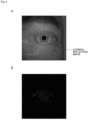
- FIG. 2A shows an image of an eyeball irradiated with light from a small point source, the image being captured by an ordinary imaging element.
- Fig. 2B shows an EVS image of an eye ball irradiated with light from a small point source.
- a small point source is used as shown in Figs. 2A and 2B , it is difficult to extract a corneal reflection image with the small point source according to a computer vision algorithm without gradation.
- a large quantity of external light such as sunlight enters a pupil as a point source, causing difficulty in identifying an eyeball.
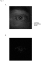
- Fig. 3A shows an image of an eyeball irradiated with light from a large point source, the image being captured by an ordinary imaging element.
- Fig. 3B shows an EVS image of an eye ball irradiated with light from a large point source.
- the light source may be upsized (for example, a circular light source having a large diameter may be used).
- the center of the circle may be a feature point of the circle but is not preferable because the radius of the circle is affected by ambiguity such as an eye movement or a corneal curvature.
- a literature (Event-Based Kilohertz Eye Tracking using Coded Differential Lighting) proposes an approach to improvement of the detection accuracy of a corneal reflection image when an EVS is used for eye tracking.
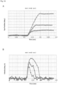
- This literature describes that the detection accuracy of Purkinje is improved by blinking two adjacent LEDs, but unfortunately control is necessary for preventing the blinking LEDs from causing an overall change in brightness, and a blinking frequency depends upon the bandwidth of the EVS. An overall change in brightness may cause simultaneous firing of events, resulting in latency.
- an eyeball may be irradiated with patterned light to increase feature points, which may cause the following problems:
- FIG. 4A shows an image of an eyeball irradiated with the patterned light PL like a rectangular frame, the image being captured by an ordinary imaging element NS.
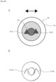
- Fig. 4B shows an image of an eyeball irradiated with the patterned light PL like a rectangular frame when moving horizontally with a relatively high velocity, the image being captured by EVS.
- Fig. 4C shows an image of an eyeball irradiated with the patterned light PL like a rectangular frame when moving horizontally with a relatively low velocity, the image being captured by EVS.
- an image PL-NS of reflected light of the patterned light PL like a rectangular frame can be clearly confirmed.
- the rectangular frame appears with double lines in an image PL-EVS of reflected light of the patterned light PL. The lines are thick and thus cause ambiguity in fitting between a light source and the reflected light.
- the rectangular frame appears with double lines in an image PL-EVS of reflected light of the patterned light PL, and the brightness hardly changes horizontally.
- the shape of the patterned light PL is considerably deformed.
- a gaze detection device as a gaze detection device (eye tracking device) that can suppress reduction in detection accuracy regardless of the imaging method of an imaging system by designing the shape of patterned light.
- the gaze detection device according to the present technique is quite effective particularly when an EVS is used for an imaging system.
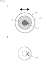
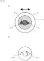
- Fig. 5A illustrates an eyeball EB irradiated with patterned light from a gaze detection device 10 according to a first embodiment of the present technique.
- Fig. 5B illustrates an EVS image of the eyeball EB.
- Fig. 6 is a block diagram illustrating a function example of a gaze detection device 10 according to the first embodiment of the present technique.
- the gaze detection device 10 is mounted on, for example, an HMD (Head Mounted Display) and is used for eye tracking (gaze detection). As illustrated in Fig. 6 , the gaze detection device 10 includes a patterned-light illumination system 100, an imaging system 200, and a gaze detection system 300.
- the gaze detection device 10 is supported by an HMD support structure (e.g., an eye glass frame) mounted on a user's head.
- the HMD displays an image superimposed on a user's field of view.
- the HMD controls the display of an image on the basis of, for example, the output (user's line of sight) of the gaze detection device 10.
- the support structure of the HMD may include a voice output device that provides voice information to a user.
- the patterned-light illumination system 100 irradiates the eyeball EB of a user with patterned light PL1 (see Fig. 5A ).
- the patterned light PL1 is triangular in shape.
- the patterned-light illumination system 100 includes, for example, a light source 100a and a light source drive unit 100b (light source driver) (see Fig. 6 ).
- the light source 100a emits invisible light (e.g., infrared light).
- the light source 100a is, for example, a point source, a line source, or a surface source.
- a light source 100a for example, an LED (Light Emitting Diode), an OLED (Organic Light Emitting Diode), or an LD (Laser Diode) can be used.
- LED Light Emitting Diode
- OLED Organic Light Emitting Diode
- LD Laser Diode
- reference character CO denotes a cornea
- reference character PU denotes a pupil.
- the patterned light PL1 has a shape along a reference pattern BP (e.g., a triangle) having at least three lines not parallel to one another, the reference pattern BP having an intersection point of at least two of the at least three lines.
- the at least three lines that constitute the reference pattern BP and are not parallel to one another include, for example, a line constituting a part of a figure, a line constituting a part of the outline of a figure, and a line constituting a part of a character.
- the at least three lines may include a straight line and a curve or at least a partially broken line as well as a solid line.
- the patterned light PL1 may have a pattern completely identical to the reference pattern BP or may have a pattern nearly identical to the reference pattern BP.
- a pattern nearly identical to the reference pattern BP includes, for example, a pattern obtained by removing at least one intersection point of the reference pattern BP and a pattern obtained by replacing at least one intersection point of the reference pattern BP with a figure.
- the patterned light PL1 completely agrees with the reference pattern BP.
- the shape of the reference pattern may be the shape of the light source or the shape of an optical element that shapes light from the light source.
- Each of the at least three (e.g., three) lines of the patterned light PL1 intersects at least one (e.g., two) of the other lines.
- each of the at least three lines of the patterned light PL1 intersects at least two (e.g., two) of the other lines.
- the reference pattern BP has at least three intersection points (e.g., three intersection points) not located on the same straight line.
- the reference pattern BP and the patterned light PL1 are each shaped like a triangle (e.g., an isosceles triangle, specifically a regular triangle) with one side extending nearly horizontally and the height direction nearly along the vertical direction.
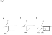
- Figs. 7A to 7C illustrate configuration examples 1 to 3 of a light source unit for the patterned-light illumination system 100 of the gaze detection device 10 according to the first embodiment of the present technique.
- the light source 100a having the same shape (e.g., a triangle) as the patterned light PL1 is provided on an eyeglass frame EF (for example, the rim of the eyeglass frame EF).
- an eyeglass frame EF for example, the rim of the eyeglass frame EF.
- the translucent light source 100a (e.g., uLED) having the same shape (e.g., a triangle) as the patterned light PL1 is provided in transparent glass or resin (for example, transparent glass or resin fit into the rim of the eyeglass frame EF) attached into the eyeglass frame EF.
- an optical element e.g., a diffraction element
- the optical element shapes light from the light source 100a into the shape of the patterned light PL1.
- the eyeglass frame may be a rimless frame.
- the light source drive unit 100b includes, for example, circuit elements such as a transistor, a capacitor, and a resistor.
- the light source drive unit 100b generates a driving signal (e.g., a pulse signal) and applies the signal to the light source 100a.
- a driving signal e.g., a pulse signal
- the imaging system 200 captures an image of the eyeball EB irradiated with the patterned light PL1 and outputs the captured image to the gaze detection system 300.
- the imaging system 200 is, for example, a camera including an imaging element 200a.
- the imaging system 200 may include, in addition to the imaging element 200a, a condensing element (e.g., a condenser lens or a condenser mirror) that condenses the patterned light PL1 onto the imaging element 200a after the patterned light PL1 is emitted to the eyeball EB from the patterned-light illumination system 100 and is reflected by the eyeball EB, and a signal processing unit that processes the output signal of the imaging element 200a.
- the imaging system 200 may include an imaging element (e.g., an ordinary image sensor) for detecting a pupil.
- the imaging element 200a is, for example, an EVS (event-based vision sensor).
- the EVS has a plurality of pixels in a two-dimensional array.
- the EVS is a vision sensor that detects a change in the brightness of each pixel and outputs the brightness value (pixel value) of only the pixel having changed in brightness in combination with time information and a vision sensor that achieves a high-speed operation and low power consumption.
- the EVS includes, for example, a light receiving circuit having a photoelectric conversion element (e.g., a photodiode having sensitivity in an infrared region) for each pixel, an amplifier, and a comparator.
- a photoelectric conversion element e.g., a photodiode having sensitivity in an infrared region
- incident light is converted into an electric signal by the light receiving circuit, is amplified by the amplifier, and is divided to be output as a positive change signal (positive event) and a negative change signal (negative event) depending upon the threshold value of brightness.
- the output signal of the EVS is output as a captured image through the signal processing unit.
- the EVS is also referred to as "event sensor” or "event vision sensor.”
- the gaze detection system 300 includes, for example, a corneal-reflection-image detection unit 300a, a pupil detection unit 300b, and a gaze detection unit 300c.
- the gaze detection system 300 may further include a storage unit (e.g., memory).
- the gaze detection system 300 is implemented by, for example, hardware such as a CPU and a chip set.
- the corneal-reflection-image detection unit 300a detects a feature point of a corneal reflection image of the patterned light PL1 from a captured image of the imaging system 200. Specifically, the corneal-reflection-image detection unit 300a detects a corneal reflection image of the patterned light PL1 from a captured image of the imaging system 200 by image processing (e.g., edge detection, outline extraction, and shade detection) and extracts a feature point of the corneal reflection image. Furthermore, the corneal-reflection-image detection unit 300a associates an intersection point of the reference pattern BP (an intersection point of the patterned light PL1) with the feature point of the corneal reflection image of the patterned light PL1.
- image processing e.g., edge detection, outline extraction, and shade detection
- Fig. 8 is a block diagram showing function example 1 of the corneal-reflection-image detection unit.
- the corneal-reflection-image detection unit 300a includes a feature point extraction unit 300a1 and an associating unit 300a2.
- the feature point extraction unit 300a1 extracts a feature point of the corneal reflection image of the patterned light PL1 by, for example, corner detection or a DNN (Deep Neural Network).
- DNN Deep Neural Network
- the associating unit 300a2 associates a feature point of the corneal reflection image of the patterned light PL1 and an intersection point of the reference pattern BP (an intersection point of the patterned light PL1) on the basis of information about an angle and/or a direction near the feature point in the captured image of the imaging system 200, stores the associating result in the storage unit (e.g., memory), and/or outputs the associating result to the gaze detection unit 300c.
- the storage unit e.g., memory
- a corneal reflection image PL1i (an output signal of the EVS) composed of two oblique side portions in a reversed V shape appears in the image captured by the EVS in response to a change in brightness in the patterned light PL1 when the eyeball EB moves in the horizontal direction.
- the feature point extraction unit 300a1 extracts the intersection point of the two oblique side portions of the corneal reflection image PL1i as a feature point of the corneal reflection image of the patterned light PL1. Moreover, the associating unit 300a2 associates the feature point and the intersection point of the patterned light PL1, from information about an angle and/or a direction (e.g., an acute angle or an upward direction) near the feature point (e.g., the intersection point of the two oblique side portions).
- a direction e.g., an acute angle or an upward direction
- the eyeball EB moves in a direction (e.g., the horizontal direction) parallel to a line of the reference pattern BP.
- a direction e.g., the horizontal direction
- the three non-parallel lines of the reference pattern BP appear in the captured image of the EVS.
- three feature points may be detected in the corneal reflection image of the reference pattern BP.
- the pupil detection unit 300b extracts a pupil from the captured image of the imaging element for detecting a pupil, calculates the center position of the pupil in the coordinate system of the captured image, and stores the calculation result in the storage unit (e.g., memory), and/or outputs the calculation result to the gaze detection unit 300c.
- image processing e.g., edge detection, outline extraction, and shade detection
- the gaze detection unit 300c detects gaze, the direction of the eyeball EB, on the basis of the detection result obtained by the pupil detection unit 300b and the detection result obtained by the corneal-reflection-image detection unit 300a on the basis of the captured image of the imaging system 200.
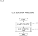
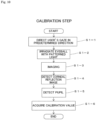
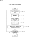
- Fig. 9 is a flowchart for describing the gaze detection processing 1.
- step S1 a calibration step is performed.
- the calibration step will be specifically described later.
- step S2 a gaze detection step is performed.
- the gaze detection step will be specifically described later. After step S2 is performed, the flow is terminated.
- Step S1 calibration step
- first step S1-1 the user's gaze is directed in a predetermined direction. Specifically, a user is notified (for example, through display by an HMD or voice by the voice output device) to look at a predetermined gaze point (e.g., the front), so that the user's gaze is directed in the predetermined direction (e.g., to the front).
- a predetermined gaze point e.g., the front
- next step S1-2 the eyeball EB is irradiated with the patterned light PL1.
- the light source 100a is driven by the light source drive unit 100b.
- next step S1-3 imaging is performed. Specifically, an image of the eyeball EB irradiated with the patterned light PL1 is captured by the imaging element (e.g., an ordinary image sensor) for detecting a pupil.
- the imaging element e.g., an ordinary image sensor
- a corneal reflection image is detected. Specifically, the corneal-reflection-image detection unit 300a extracts the feature point of the corneal reflection image of the patterned light PL1 from the image captured in step S1-3, and associates the feature point and the intersection point of the patterned light PL1.
- next step S1-5 a pupil is detected.
- the pupil detection unit 300b extracts a pupil PU from the captured image of the imaging element for detecting a pupil and detects the center position of the pupil.
- a calibration value is acquired. Specifically, the positional relationship (see Fig. 12 ) between the center of the pupil detected in step S1-5 and the corneal reflection image of the intersection point of the patterned light PL1 is associated with the gaze direction (e.g., to the front) and is acquired as a calibration value, the corneal reflection image being detected in step S1-4, and then the calibration value is stored in the storage unit (e.g., memory).
- the storage unit e.g., memory
- the accuracy of the calibration value can be increased by performing the series of steps S1-1 to S1-6 several times to obtain multiple calibration values and using the mean value or the median value of the calibration values.
- the predetermined direction in step S1-1 in each time may be the same direction or different directions.
- Step S2 Gaze Detection Step
- first step S2-1 the eyeball EB is irradiated with the patterned light PL1.
- the light source 100a is driven by the light source drive unit 100b.
- next step S2-2 imaging is performed.
- the imaging element 200a (EVS) of the imaging system 200 captures an image of the eyeball EB irradiated with the patterned light PL1 and outputs the captured image (see Figs. 11B and 11C).
- Fig. 11A shows an image of the eyeball EB irradiated with the patterned light PL1, the image being captured by an ordinary imaging element NS.
- Fig. 11B shows an EVS image of the eyeball irradiated with the patterned light PL1 when the eyeball moves horizontally with a relatively high velocity.
- Fig. 11C shows an EVS image of the eyeball irradiated with the patterned light PL1 when the eyeball moves horizontally with a relatively low velocity.
- FIG. 11A an image PL1-NS of reflected light of the patterned light PL1 can be clearly confirmed.
- Fig. 11B although two oblique sides appear thickly as double lines in an image PL1-EVS of reflected light of the patterned light PL1, a corner composed of the two oblique sides and the intersection point thereof can be detected all the time, enabling robust detection of the eyeball EB moving at high velocity. Also in Fig.
- a corneal reflection image is detected. Specifically, the corneal-reflection-image detection unit 300a extracts the feature point of the corneal reflection image of the patterned light PL1 and associates the feature point and the intersection point of the patterned light PL1.
- next step S2-4 a pupil is detected.
- the pupil detection unit 300b extracts the pupil PU from the captured image of the imaging element for detecting a pupil and detects the center position of the pupil.
- a gaze is detected on the basis of a calibration value. Specifically, the gaze direction is determined on the basis of the positional relationship between the center of the pupil detected in step S2-4 and the corneal reflection image of each intersection point of the patterned light PL1, the corneal reflection image being detected in step S2-3, and the calibration value that is acquired in the calibration step (step S1) and is stored in the storage unit.
- step S2-6 whether to terminate the gaze detection is determined.
- the termination is acknowledged.
- the termination is rejected to perform the gaze detection again (steps S2-1 to S2-5).
- the gaze detection device 10 includes the patterned-light illumination system 100 that irradiates the eyeball EB with the patterned light PL1, the imaging system 200 that captures an image of the eyeball EB irradiated with the patterned light PL1, and the gaze detection system 300 that detects a gaze as the direction of the eyeball EB on the basis of the captured image of the imaging system 200.
- the patterned light PL1 has a shape along the reference pattern BP having at least three lines not parallel to one another, the reference pattern BP having an intersection point of at least two of the at least three lines.
- the imaging method of the imaging system 200 is the event-based vision method
- at least two non-parallel lines of the patterned light PL1 can be detected in the captured image regardless of the direction of movement of the eyeball EB irradiated with the patterned light PL1, so that a feature point (e.g., an intersection point) formed by the at least two lines can be extracted.
- the gaze detection device 10 capable of suppressing reduction in detection accuracy can be provided regardless of the imaging method of the imaging system 200. If the imaging method of the imaging system 200 is not the event-based vision method (for example, in the case of an ordinary image sensor), the gaze detection device 10 can detect at least three non-parallel lines of the patterned light PL1 in the captured image, thereby extracting a feature point (e.g., an intersection point) formed by the at least three lines. Also in this case, the gaze detection device capable of suppressing reduction in detection accuracy can be provided.
- the imaging method of the imaging system 200 is not the event-based vision method (for example, in the case of an ordinary image sensor)
- the gaze detection device 10 can detect at least three non-parallel lines of the patterned light PL1 in the captured image, thereby extracting a feature point (e.g., an intersection point) formed by the at least three lines. Also in this case, the gaze detection device capable of suppressing reduction in detection accuracy can be provided.
- Each of the at least three (e.g., three) lines of the reference pattern BP crosses at least one (e.g., two) of the other lines.
- the patterned light PL1 can have quite a simple shape that allows detection of a feature point regardless of the imaging method.
- the light source and the optical element that are used for generating the patterned light PL1 can have quite simple shapes.
- the patterned light PL1 can have a simple shape that allows detection of a feature point regardless of the imaging method.
- the light source and the optical element that are used for generating the patterned light PL1 can have simple shapes.
- the reference pattern BP has at least three intersection points on the same straight line.
- at least one feature point (e.g., one intersection point) of the patterned light PL1 can be detected in the captured image regardless of the direction of movement of the eyeball EB irradiated with the patterned light PL1, thereby improving the detection accuracy.
- the gaze detection system 300 includes the corneal-reflection-image detection unit 300a that detects a feature point (e.g., an intersection point) of the corneal reflection image of the patterned light PL1 from the captured image of the imaging system 200. This enables robust detection of a movement of the eyeball EB.
- a feature point e.g., an intersection point
- the corneal-reflection-image detection unit 300a associates the intersection point of the reference pattern BP and the feature point on the basis of information about an angle and/or a direction near the feature point (e.g., the intersection point of the reference pattern BP) of the corneal reflection image of the reference pattern BP in the captured image of the imaging system 200. This can associate the intersection point and the feature point with high accuracy.
- the gaze detection system 300 detects a gaze on the basis of the captured image of the imaging system 200 and the detection result of the corneal-reflection-image detection unit 300a. This can detect a gaze with high accuracy.
- the patterned-light illumination system 100 may include the light source 100a that emits patterned light.
- the light source 100a can have a simple shape and thus is easy to manufacture.
- the patterned-light illumination system 100 may include the light source 100a and the optical element that shapes light from the light source 100a to generate the patterned light PL1.
- the optical element can have a simple shape and thus is easy to manufacture.
- the imaging system 200 includes the EVS. This enables high-speed imaging with low power consumption.
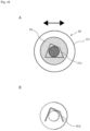
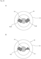
- Fig. 14A illustrates an eyeball irradiated with patterned light from a gaze detection device according to modification example 1 of the first embodiment of the present technique.
- Fig. 14B illustrates an EVS image of the eyeball.
- the gaze detection device according to modification example 1 of the first embodiment has the same configuration as the gaze detection device 10 according to the first embodiment except that patterned light PL2 emitted from the patterned-light illumination system 100 to the eyeball EB has a different shape from the patterned light PL1.
- the reference pattern BP has at least three non-parallel lines (e.g., three lines) that cross at the same intersection point and extend radially from the intersection point.
- the reference pattern BP has a horizontally oriented Y shape (a Y shape rotated 90°). In this pattern, the patterned light PL2 completely agrees with the reference pattern BP.
- a corneal reflection image PL2i of the patterned light PL2 does not have any horizontal lines with constant brightness in the EVS image but has two oblique lines with a change in brightness.
- the intersection point of the two oblique lines is extracted as a feature point, enabling gaze detection with high accuracy.
- the same effect as the gaze detection device 10 according to the first embodiment can be obtained, and the reference pattern BP has the single intersection point (the intersection point of the patterned light PL2).
- the corneal reflection image and the intersection point can be easily associated with each other, enabling gaze detection at higher speed.
- Fig. 15A illustrates an eyeball irradiated with patterned light from a gaze detection device according to modification example 2 of the first embodiment of the present technique.
- Fig. 15B illustrates an EVS image of the eyeball.
- the gaze detection device according to modification example 2 of the first embodiment has the same configuration as the gaze detection device 10 according to the first embodiment except that patterned light PL3 emitted from the patterned-light illumination system 100 to the eyeball EB has a different shape from the patterned light PL1.
- the reference pattern BP has at least three non-parallel lines that cross at the same intersection point and form consecutive acute angles around the intersection point.
- the reference pattern BP is shaped like a horizontally oriented arrow. In this pattern, the patterned light PL3 completely agrees with the reference pattern BP.
- a corneal reflection image PL3i of the patterned light PL3 does not have any horizontal lines with constant brightness in the EVS image but has two oblique lines with a change in brightness.
- the intersection point of the two oblique lines is extracted as a feature point, enabling gaze detection with high accuracy.
- the same effect as the gaze detection device 10 according to the first embodiment can be obtained, and the reference pattern BP has the single intersection point (the intersection point of the patterned light PL3).
- the corneal reflection image and the intersection point can be easily associated with each other, enabling gaze detection at higher speed.
- Fig. 16A illustrates an eyeball irradiated with patterned light PL5 from a gaze detection device according to modification example 3 of the first embodiment of the present technique.
- Fig. 16B illustrates an EVS image of the eyeball.
- the gaze detection device according to modification example 3 of the first embodiment has the same configuration as the gaze detection device 10 according to the first embodiment except that patterned light PL5 emitted from the patterned-light illumination system 100 to the eyeball EB has a different shape from the patterned light PL1.
- the reference pattern BP has at least three (e.g., four) non-parallel lines, each crossing at least two (e.g., two) of the other lines.
- the reference pattern BP is shaped like a quadrilateral having four non-parallel sides, one of which is nearly parallel to the horizontal direction.
- the size of the reference pattern BP is greater than or equal to the size of the pupil PU.
- the patterned light PL5 completely agrees with the reference pattern BP.
- a corneal reflection image PL5i of the patterned light PL5 does not have any horizontal lines with constant brightness in the EVS image but has three oblique lines with a change in brightness (see Fig. 16B ). Two intersection points formed by the three oblique lines are extracted as feature points, enabling gaze detection with high accuracy.
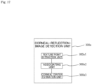
- Fig. 17 is a block diagram showing function example 2 of the corneal-reflection-image detection unit.
- the corneal-reflection-image detection unit 300a includes the feature point extraction unit 300a1, the associating unit 300a2, and a corneal center estimation unit 300a3.
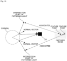
- Fig. 18 illustrates an operation example of the corneal-reflection-image detection unit of Fig. 17 .
- the feature point extraction unit 300a1 extracts a plurality of feature points of the corneal reflection image PL5i of the patterned light PL5 from the EVS image.
- the associating unit 300a2 associates the feature points extracted by the feature point extraction unit 300a1 and the intersection points of the patterned light PL5.
- the corneal center estimation unit 300a3 determines the reflecting points of the plurality of corresponding intersection points of the patterned light PL5 on the corneal, determines normal vectors passing through the respective reflecting points, estimates the intersection point of the normal vectors as a corneal center (the center of a corneal CO) in the coordinate system of the captured image, and outputs the estimation result to the gaze detection unit 300c.
- the pupil detection unit 300b extracts a pupil from the captured image of the imaging element for detecting a pupil, calculates the center position of the pupil in the coordinate system of the captured image, and outputs the calculation result to the gaze detection unit 300c.
- image processing e.g., edge detection, outline extraction, and shade detection
- the gaze detection unit 300c determines a gaze direction on the basis of the corneal center as the estimation result of the corneal center estimation unit 300a3 and the pupil center as the detection result of the pupil detection unit 300b.
- Fig. 19 is a flowchart for describing the gaze detection processing 2.
- first step S11 the eyeball EB is irradiated with patterned light.
- the light source 100a is driven by the light source drive unit 100b.
- next step S12 imaging is performed.
- the imaging element 200a (EVS) of the imaging system 200 captures an image of the eyeball EB irradiated with the patterned light and outputs the captured image.
- a corneal reflection image is detected. Specifically, the corneal-reflection-image detection unit 300a extracts multiple feature points of the corneal reflection image of the patterned light from the captured image, and associates corneal reflection images and the intersection points of the patterned light.
- the corneal center is estimated. Specifically, the corneal-reflection-image detection unit 300a calculates the corneal center of the corneal CO on the basis of the feature points of the corneal reflection image of the patterned light.
- next step S15 a pupil is detected.
- the pupil detection unit 300b extracts the pupil PU from the captured image of the imaging element for detecting a pupil and detects the center position of the pupil.
- a gaze is detected. Specifically, a gaze direction is determined on the basis of the corneal center estimated in step S14 and the pupil center detected in step S15.
- step S17 whether to terminate the gaze detection is determined.
- the gaze detection device according to modification example 3 is turned off, the termination is acknowledged.
- the gaze detection device is turned on, the termination is rejected to perform the gaze detection again (steps S11 to S16).
- the gaze detection device of modification example 3 at least two feature points of the corneal reflection image of the patterned light PL5 can be detected all the time, so that a gaze can be detected by the gaze detection processing 2 that does not require calibration. Furthermore, the patterned light PL5 is relatively large, so that a feature point of the corneal reflection image is easily detected.
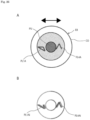
- Fig. 20A illustrates an eyeball irradiated with patterned light PL1 from a gaze detection device according to a second embodiment of the present technique.
- Fig. 20B illustrates an EVS image of the eyeball.
- Fig. 21 is a block diagram illustrating a function example of a gaze detection device 20 according to the second embodiment of the present technique.
- the gaze detection device 20 according to the second embodiment has the same configuration as the gaze detection device 10 according to the first embodiment except that a reference pattern BP has multiple (e.g., two) patterns (e.g., triangular patterns), each including at least two (e.g., three) lines crossing each other.
- a reference pattern BP has multiple (e.g., two) patterns (e.g., triangular patterns), each including at least two (e.g., three) lines crossing each other.
- the reference pattern BP includes at least two (e.g., two) patterns that are identical in shape (including a similar figure, same as below) and are oriented in the same direction.
- patterned light corresponding to the reference pattern BP completely agrees with the reference pattern BP.
- the patterned light corresponding to the reference pattern BP includes, for example, multiple (e.g., two) first and second pattern portions PL1A and PL1B that are identical in shape and are oriented in the same direction as illustrated in Fig. 20A .
- the patterns of the reference pattern BP and the pattern portions of the patterned light are triangular in shape with one side extending nearly horizontally.
- a corneal reflection image PL1Ai of the first pattern portion PL1A and a corneal reflection image PL1Bi of the second pattern portion PL1B appear in an EVS image when an eyeball EB moves horizontally.
- the corneal reflection images each have a reversed V shape with one intersection point.
- a patterned-light illumination system 100 includes first and second light sources 100a1 and 100a2 as illustrated in Fig. 21 .
- the first light source 100a1 is used for generating the first pattern portion PL1A.
- the second light source 100a2 is used for generating the second pattern portion PL1B.
- the first and second light sources 100a1 and 100a2 are driven by a light source drive unit 100b.
- gaze detection processing 2 is performed. At this point, a feature point (an intersection point of the first pattern portion PL1A) of the corneal reflection image PL1Ai and a feature point (an intersection point of the second pattern portion PL1B) of the corneal reflection image PL1Bi are extracted, and then the corneal center is calculated using the feature points.
- the gaze detection device 20 at least two feature points of the corneal reflection image of the patterned light can be detected all the time, so that a gaze can be detected by the gaze detection processing 2 that does not require calibration.
- the patterned-light illumination system 100 may irradiate the eyeball EB only with portion of patterned light (a pattern portion where a feature point is detectable), the portion corresponding to the pattern where an intersection point is detectable among the multiple patterns of the reference pattern BP.
- a pattern portion where a feature point is detectable the portion corresponding to the pattern where an intersection point is detectable among the multiple patterns of the reference pattern BP.
- the contrast can be increased and signals are easily obtained by reducing the number of divisions of patterned light (when patterned light is not divided, the number of divisions is 1).
- Whether an intersection point is detectable in the multiple patterns of the reference pattern BP can be determined by the estimation result (e.g., the direction of movement of the eyeball EB) of a movement information estimation unit 300d, which will be described later.
- the estimation result e.g., the direction of movement of the eyeball EB
- a movement information estimation unit 300d which will be described later.
- the above-mentioned selective irradiation method of patterned light is also applicable to gaze detection devices according to other embodiments and modification examples.
- Fig. 22A illustrates an eyeball irradiated with patterned light from a gaze detection device according to modification example 1 of the second embodiment of the present technique.
- Fig. 22B illustrates an EVS image of the eyeball.
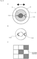
- Fig. 22C is an explanatory drawing of a method for detecting an intersection point from the captured image.
- the gaze detection device has the same configuration as the gaze detection device 20 according to the second embodiment except that patterned light emitted to the eyeball EB has first and second pattern portions PL2A and PL2B, each having a horizontally oriented Y shape (a Y shape rotated 90°).
- a corneal reflection image PL2Ai of the first pattern portion PL2A and a corneal reflection image PL2Bi of the second pattern portion PL2B appear in an EVS image when the eyeball EB moves horizontally.
- the corneal reflection images each have a horizontally oriented V shape (a V shape rotated 90°) with one intersection point.
- gaze detection processing 2 is performed.
- the corneal-reflection-image detection unit 300a extracts a feature point (an intersection point of the first pattern portion PL2A) of the corneal reflection image PL2Ai and a feature point (an intersection point of the second pattern portion PL2B) of the corneal reflection image PL2Bi and calculates the corneal center by using the feature points.
- At least two feature points of the corneal reflection image of the patterned light can be detected all the time, so that a gaze can be detected by the gaze detection processing 2 that does not require calibration. Even when the pattern portions are relatively small, a large acute angle can be obtained, so that a feature point (e.g., an intersection point) is easily detected (see Fig. 22C ).
- Fig. 23A illustrates an eyeball irradiated with patterned light from a gaze detection device according to modification example 2 of the second embodiment of the present technique.
- Fig. 23B illustrates an EVS image of the eyeball.
- the gaze detection device according to modification example 2 of the second embodiment has the same configuration as the gaze detection device 20 according to the second embodiment except that patterned light emitted to the eyeball EB has first and second pattern portions PL1A and PL1' in different shapes.
- the first pattern portion PL1A is triangular in shape with one side extending nearly horizontally.
- the second pattern portion PL1' is shaped like a triangle dissimilar to the first pattern portion PL1A and has all the sides not parallel to any one of the sides of the first pattern portion PL1A.
- a corneal reflection image PL1Ai of the first pattern portion PL1A and a corneal reflection image PL1'i of the second pattern portion PL1' appear in an EVS image when the eyeball EB moves horizontally.
- the corneal reflection image PL1Ai has a reversed V shape, and the corneal reflection image PL1'i is triangular in shape (nearly identical in shape to the second pattern portion PL1').
- gaze detection processing 2 is performed.
- the corneal-reflection-image detection unit 300a extracts a feature point (an intersection point of the first pattern portion PL1A) of the corneal reflection image PL1Ai and a feature point (an intersection point of the second pattern portion PL1') of the corneal reflection image PL1' and calculates the corneal center by using the feature points.
- At least two feature points of the corneal reflection image of the patterned light can be detected all the time, so that a gaze can be detected by the gaze detection processing 2 that does not require calibration. Moreover, multiple feature points of the corneal reflection image can be detected, enabling gaze detection with higher accuracy.
- Fig. 24A illustrates an eyeball irradiated with patterned light from a gaze detection device according to modification example 3 of the second embodiment of the present technique.
- Fig. 24B illustrates an EVS image of the eyeball.
- the gaze detection device has the same configuration as the gaze detection device 20 according to the second embodiment except that patterned light emitted to the eyeball EB has first and second pattern portions PL2A and PL2B that are identical in shape and are oriented in different directions.
- the first pattern portion PL2A has a Y shape rotated by an acute angle or an obtuse angle (e.g., an obtuse angle).
- the second pattern portion PL2B has a horizontally oriented Y shape (a Y shape rotated 90°). In other words, the second pattern portion PL2B has three straight lines constituting the Y shape such that the straight lines are not parallel to any one of three straight lines constituting the Y shape of the first pattern portion PL2A.
- a corneal reflection image PL2Ai of the first pattern portion PL2A and a corneal reflection image PL2Bi of the second pattern portion PL2B appear in an EVS image when the eyeball EB moves horizontally.
- the corneal reflection image PL1Ai has a Y shape rotated by an obtuse angle (nearly identical in shape to the first pattern portion PL2A).
- the corneal reflection image PL2Bi has a horizontally oriented V shape (a V shape rotated 90°).
- gaze detection processing 2 is performed.
- the corneal-reflection-image detection unit 300a extracts a feature point (an intersection point of the first pattern portion PL2A) of the corneal reflection image PL2Ai and a feature point (an intersection point of the second pattern portion PL2B) of the corneal reflection image PL2Bi and calculates the corneal center by using the feature points.
- At least two feature points of the corneal reflection image of the patterned light can be detected all the time, so that a gaze can be detected by the gaze detection processing 2 that does not require calibration.
- Fig. 25A illustrates an eyeball irradiated with patterned light from a gaze detection device according to modification example 4 of the second embodiment of the present technique.
- Fig. 25B illustrates an EVS image of the eyeball.
- the gaze detection device has the same configuration as the gaze detection device 20 according to the second embodiment except that patterned light emitted to the eyeball EB has first and second pattern portions PL4A and PL4B that are identical in shape and are oriented in different directions.
- the first pattern portion PL4A has a V shape rotated by an acute angle or an obtuse angle (e.g., an obtuse angle).
- the second pattern portion PL4B has a V shape rotated by an acute angle or an obtuse angle (e.g., an obtuse angle) and oriented in a different direction from the first pattern portion PL4A.
- the second pattern portion PL4B has two straight lines constituting the V shape such that the straight lines are not parallel to any one of two straight lines constituting the V shape of the first pattern portion PL4A.
- a corneal reflection image PL4Ai of the first pattern portion PL4A and a corneal reflection image PL4Bi of the second pattern portion PL4B appear in an EVS image when an eyeball EB moves horizontally.
- the corneal reflection image PL4Ai is nearly identical in shape to the first pattern portion PL4A.
- the corneal reflection image PL4Bi is nearly identical in shape to the second pattern portion PL4B.
- gaze detection processing 1 is performed.
- the corneal-reflection-image detection unit 300a extracts a feature point (an intersection point of the first pattern portion PL4A) of the corneal reflection image PL4Ai and/or a feature point (an intersection point of the second pattern portion PL4B) of the corneal reflection image PL4Bi.
- At least one feature point of the corneal reflection image can be extracted all the time even when patterned light has quite a simple shape, so that a gaze can be detected all the time.
- Fig. 26A illustrates an eyeball irradiated with patterned light from a gaze detection device according to modification example 5 of the second embodiment of the present technique.
- Fig. 26B illustrates an EVS image of the eyeball.
- the gaze detection device according to modification example 5 of the second embodiment has the same configuration as the gaze detection device 20 according to the second embodiment except that patterned light emitted to the eyeball EB has first and second pattern portions PL1A and PL4A in different shapes.
- the first pattern portion PL1A is nearly triangular in shape with one side extending nearly horizontally.
- the second pattern portion PL4A has a reversed V shape.
- the lines of the second pattern portion PL4A are not parallel to any one of the three sides of the first pattern portion PL1A.
- a corneal reflection image PL1Ai of the first pattern portion PL1A and a corneal reflection image PL4Ai of the second pattern portion PL4A appear in an EVS image when the eyeball EB moves horizontally.
- the corneal reflection image PL1Ai is shaped like the first pattern portion PL1A having a missing horizontal line.
- the corneal reflection image PL4Ai is nearly identical in shape to the second pattern portion PL4A.
- gaze detection processing 2 is performed.
- the corneal-reflection-image detection unit 300a extracts a feature point (an intersection point of the first pattern portion PL1A) of the corneal reflection image PL1Ai and a feature point (an intersection point of the second pattern portion PL4A) of the corneal reflection image PL4Ai and calculates the corneal center by using the feature points.
- At least two feature points of the corneal reflection image of the patterned light can be detected all the time, so that a gaze can be detected by the gaze detection processing 2 that does not require calibration.
- Fig. 27A illustrates an eyeball irradiated with patterned light from a gaze detection device according to a third embodiment of the present technique.
- Fig. 27B illustrates an EVS image of the eyeball.
- Fig. 28 is a block diagram illustrating a function example of a gaze detection device 30 according to the third embodiment of the present technique.
- the gaze detection device 30 according to the third embodiment has the same configuration as the gaze detection device 10 according to the first embodiment except that a reference pattern BP has multiple (e.g., three) patterns, each including at least two (e.g., two) lines crossing each other.
- a reference pattern BP has multiple (e.g., three) patterns, each including at least two (e.g., two) lines crossing each other.
- the reference pattern BP includes at least two (e.g., three) patterns that are identical in shape and are oriented in different directions.
- patterned light corresponding to the reference pattern BP completely agrees with the reference pattern BP.
- the patterned light corresponding to the reference pattern BP includes, for example, multiple (e.g., three) first to third pattern portions PL4A, PL4B, and PL4C that are identical in shape and are oriented in different direction as illustrated in Fig. 27A .
- the patterns of the reference pattern BP and the pattern portions of the patterned light are nearly V-shaped. Specifically, for example, two straight lines constituting the V shape of each pattern portion are not parallel to any one of two straight lines constituting the V shape of another pattern portion.
- the third pattern portion PL4C has one side extending nearly horizontally.
- a corneal reflection image PL4Ai of the first pattern portion PL4A, a corneal reflection image PL4Bi of the second pattern portion PL4B, and a corneal reflection image PL4Ci of the third pattern portion PL4C appear in an EVS image when an eyeball EB moves horizontally.
- the corneal reflection images PL4Ai and PL4Bi are each V-shaped with one intersection point.
- the corneal reflection images PL4Ci is a straight line.
- a patterned-light illumination system 100 includes first to third light sources 100a1, 100a2, and 100a3 as illustrated in Fig. 28 .
- the first light source 100a1 is used for generating the first pattern portion PL4A.
- the second light source 100a2 is used for generating the second pattern portion PL4B.
- the third light source 100a3 is used for generating the third pattern portion PL4C.
- the first to third light sources 100a1, 100a2, and 100a3 are driven by a light source drive unit 100b.
- gaze detection processing 2 is performed. At this point, a feature point (an intersection point of the first pattern portion PL4A) of the corneal reflection image PL4Ai, a feature point (an intersection point of the second pattern portion PL4B) of the corneal reflection image PL4Bi, and a feature point (an intersection point of the third pattern portion PL4C) of the corneal reflection image PL4Ci are extracted, and the corneal center is calculated using the feature points.
- the gaze detection device 30 at least two feature points of the corneal reflection image of the patterned light can be detected all the time, so that a gaze can be detected by the gaze detection processing 2 that does not require calibration.
- a corneal-reflection-image detection unit 300a may extract, as a feature point, a pixel having increased in brightness in an EVS image.
- Fig. 29 is a block diagram illustrating function example 3 of the corneal-reflection-image detection unit.
- function example 3 of the corneal-reflection-image detection unit 300a includes a brightness comparison unit 300a4 in addition to a feature point extraction unit 300a1 and an associating unit 300a2.
- the brightness comparison unit 300a4 compares the brightness of pixels in the current frame and the brightness of pixels in the preceding frame, the pixels constituting a feature point that is extracted by the feature point extraction unit 300a1 and is associated by the associating unit 300a2.
- the brightness comparison unit 300a4 then extracts only the pixel having increased in brightness from the pixels, as a pixel constituting the feature point.
- the feature point can be more strictly extracted.
- Fig. 30 is a block diagram illustrating a function example of a gaze detection device 40 according to the fourth embodiment of the present technique.
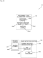
- the gaze detection device 40 according to the fourth embodiment has nearly the same configuration as the gaze detection device 10 according to the first embodiment except that a gaze detection system 300 further includes a movement information estimation unit 300d.
- the movement information estimation unit 300d estimates at least one of the amount of movement, the direction of movement, and the velocity of movement of an eyeball EB on the basis of the detection result in a corneal-reflection-image detection unit 300a.
- Fig. 31 is a block diagram showing function example 1 of the movement information estimation unit 300d.
- the movement information estimation unit 300d in Fig. 31 includes a movement amount estimation unit 300d1 and a movement direction estimation unit 300d2.
- the movement amount estimation unit 300d1 can extract, for example, a feature point having decreased in brightness and a feature point having increased in brightness and estimate the amount of movement of the eyeball EB from the positional relationship between the two feature points.
- the movement direction estimation unit 300d2 can estimate the direction of movement of the eyeball EB from the positional relationship or estimate the direction of movement of the eyeball EB from, for example, the direction of an acute angle formed by two straight lines crossing at the feature point (intersection point) of a corneal reflection image PL4i or an event polarity (positive or negative) as shown in Fig. 32 .
- a gaze detection unit 300c performs gaze detection processing 1.
- the amount of movement and the direction of movement of the eyeball EB are associated with gaze in addition to the feature point of a corneal reflection image and the center of a pupil, the amount and direction of movement being estimated by the movement information estimation unit 300d, so that a gaze can be determined with higher accuracy.
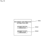
- Fig. 33 is a block diagram showing function example 2 of the movement information estimation unit 300d.
- the movement information estimation unit 300d in Fig. 33 includes the movement direction estimation unit 300d2 and a movement velocity estimation unit 300d3.
- the movement direction estimation unit 300d2 can extract, for example, a feature point having decreased in brightness and a feature point having increased in brightness and estimate the direction of movement of the eyeball EB from the positional relationship between the two feature points or estimate the direction of movement of the eyeball EB from, for example, the direction of an acute angle formed by two straight lines crossing at the feature point (intersection point) of the corneal reflection image PL4i or an event polarity (positive or negative) as shown in Fig. 32 .
- the movement velocity estimation unit 300d3 may extract, for example, a feature point having decreased in brightness and a feature point having increased in brightness and estimate the velocity of movement of the eyeball EB from the positional relationship between the two feature points and the frame rate of an EVS.
- Figs. 34A and 34B are explanatory drawings showing the principle of the function example 2 of the movement information estimation unit 300d.
- Figs. 34A and 34B show a change of an eyeball position and a change of an eyeball velocity over time with respect to the same movement of the eyeball.
- Figs. 34A and 34B show that a change of an eyeball position and a change of an eyeball velocity over time are associated with each other and the arrival time of the eyeball can be detected by detecting the maximum velocity.
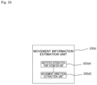
- Fig. 35 is a block diagram showing function example 3 of the movement information estimation unit 300d.
- the movement information estimation unit 300d in Fig. 35 estimates the position of a feature point that corresponds to an intersection point and has been undetected by the corneal-reflection-image detection unit 300a (has not appeared in an EVS image), from a feature point that corresponds to an intersection point and has been detected by the corneal-reflection-image detection unit 300a (has appeared in an EVS image), and then extracts the direction of movement of the eyeball EB from the estimation result.
- the movement information estimation unit 300d includes an undetected-intersection-point estimation unit 300d4 and a movement direction extraction unit 300d5.
- Fig. 35 is a block diagram showing function example 3 of the movement information estimation unit 300d.
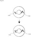
- the undetected-intersection -point estimation unit 300d4 estimates the position of a feature point (e.g., a feature point of a corneal reflection image PL4Ai) that corresponds to an intersection point of the reference pattern BP and has been undetected by the corneal-reflection-image detection unit 300a (has not appeared in an EVS image), from the position of a feature point (e.g., a feature point of a corneal reflection image PL4Bi) that corresponds to an intersection point of the reference pattern BP and has been detected by the corneal-reflection-image detection unit 300a (for example, the broken line portion of Fig. 36 can be estimated), and then the undetected-intersection-point estimation unit 300d4 outputs the estimation result.
- This can increase the number of feature points, improve the accuracy of detection for the gaze detection processing 1, and also support the gaze detection processing 2.
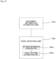
- Fig. 37 is a block diagram showing a function example of a pupil detection unit 300b.
- the pupil detection unit 300b in Fig. 37 includes a movement information acquisition unit 300b1 and a pupil pattern estimation unit 300b2.
- the movement information acquisition unit 300b1 acquires movement information (e.g., at least one of the amount of movement, the direction of movement, and the velocity of movement) about the eyeball EB as the estimation result of the movement information estimation unit 300d.
- the pupil pattern estimation unit 300b2 estimates the pattern of a pupil from the movement information acquired about the eyeball EB by the movement information acquisition unit 300b1 and detects the pupil through pattern detection or the like.
- the gaze detection system 300 includes the movement information estimation unit 300d, thereby further improving the accuracy of gaze detection.
- Figs. 38A and 38B illustrate eyeballs irradiated with patterned light from gaze detection devices according to modification examples 6 and 7 of the second embodiment of the present technique.
- patterned light emitted to the eyeball EB includes rectangular first and second pattern portions PL6A and PL6B that are identical in shape (including a similar figure) and are oriented in different directions.
- patterned light emitted to the eyeball EB includes a rectangular first pattern portion PL6 and a triangular second pattern portion PL1'.
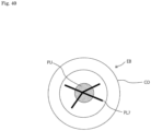
- Figs. 39A to 39E illustrate eyeballs irradiated with patterned light from gaze detection devices according to modification examples 4 to 8 of the first embodiment of the present technique.
- all the reference patterns BP corresponding to patterned light extend radially (e.g., in a Y shape).
- the patterned light PL2 is shaped to extend along the reference pattern BP such that two of three straight lines cross each other with a straight line slightly separated (e.g., by ten pixels or less) from the intersection point of the two straight lines.
- the patterned light PL2 is shaped to extend along the reference pattern BP such that a portion corresponding to the intersection point of the reference pattern BP is replaced with a figure (e.g., a circle).
- the patterned light PL2 is shaped to extend along the reference pattern BP such that a portion corresponding to the intersection point of the reference pattern BP is removed.
- the patterned light PL2 is shaped to extend along the reference pattern BP such that a portion corresponding to the intersection point of the reference pattern BP is removed and a figure (e.g., a circle) is placed in the removed portion.
- Fig. 40 illustrates an eyeball irradiated with patterned light from a gaze detection device according to modification example 9 of the first embodiment of the present technique.
- patterned light PL7 has three non-parallel straight lines crossing at a point. Four line segments extend radially from the intersection point of the three straight lines.
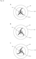
- Figs. 41A to 41C illustrate eyeballs irradiated with patterned light from gaze detection devices according to modification examples 10 to 12 of the first embodiment of the present technique.
- patterned light PL9 is A-shaped with three intersection points.
- patterned light PL10 is A-shaped to have a laterally extending horizontal line with three intersection points.
- patterned light PL11 is A-shaped to have a laterally extending horizontal line and two oblique lines extending upward with three intersection points.
- Figs. 42A to 42C illustrate eyeballs irradiated with patterned light from gaze detection devices according to modification examples 13 to 15 of the first embodiment of the present technique.
- patterned light PL12 is shaped such that a curve and two straight lines cross one another at a point and extend radially from the intersection point.
- the patterned light PL12 may be shaped such that a curve and two straight lines cross one another at multiple points.
- patterned light PL13 is shaped such that two curves and a straight line cross one another at a point.
- the patterned light PL13 may be shaped such that two curves and a straight line cross one another at multiple points.
- patterned light PL14 is shaped with three curves crossing at a point.
- the patterned light PL14 may be shaped with three curves crossing at multiple points.
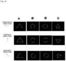
- Fig. 43 shows variation 1 of patterned light suitable for the gaze detection device according to the present technique and corneal reflection images of the patterned light.
- Fig. 43 shows the patterned light shaped like stars in addition to polygons such as a triangle, a pentagon, and a hexagon.
- an EVS image in each direction e.g., the horizontal direction, the vertical direction, and a diagonal direction
- Fig. 43 shows that at least one feature point (intersection point) of a corneal reflection image can be detected from patterned light in any shape with respect to a horizontal movement, a vertical movement, and a diagonal movement of the eyeball.
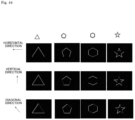
- Fig. 44 shows variation 2 of patterned light suitable for the gaze detection device according to the present technique and corneal reflection images of the patterned light.
- Fig. 44 shows the patterned light shaped like star frames in addition to polygonal frames such as a triangular frame, a pentagonal frame, and a hexagonal frame.
- an EVS image in each direction e.g., the horizontal direction, the vertical direction, and a diagonal direction
- Fig. 44 shows that at least one feature point (intersection point) of a corneal reflection image can be detected from patterned light in any shape with respect to a horizontal movement, a vertical movement, and a diagonal movement of the eyeball.
- the number of light sources and the number of optical elements can be changed as appropriate.
- the number of light sources and the number of optical elements can be determined according to the number of divisions of patterned light (the number of pattern portions). Specifically, when light sources emit the pattern portions of patterned light, the number of light sources may be set equal to the number of pattern portions. When light emitted from light sources is shaped into pattern portions through optical elements, the number of optical elements may be set equal to the number of pattern portions and the number of light sources may be set equal to or smaller than the number of pattern portions.
- the imaging element 200a of the imaging system is not limited to an EVS and may be an ordinary image sensor.
- the type, number, shape, and arrangement of the light sources and optical elements can be changed as appropriate.
- the gaze detection devices according to the embodiments and modification examples may be combined without inconsistencies.
- the present technique can also be configured as follows:
Landscapes
- Engineering & Computer Science (AREA)
- Health & Medical Sciences (AREA)
- Life Sciences & Earth Sciences (AREA)
- Physics & Mathematics (AREA)
- General Physics & Mathematics (AREA)
- Theoretical Computer Science (AREA)
- Ophthalmology & Optometry (AREA)
- General Health & Medical Sciences (AREA)
- Heart & Thoracic Surgery (AREA)
- Surgery (AREA)
- Human Computer Interaction (AREA)
- Veterinary Medicine (AREA)
- Public Health (AREA)
- Biophysics (AREA)
- Biomedical Technology (AREA)
- Animal Behavior & Ethology (AREA)
- Medical Informatics (AREA)
- Molecular Biology (AREA)
- General Engineering & Computer Science (AREA)
- Multimedia (AREA)
- Computer Vision & Pattern Recognition (AREA)
- Optics & Photonics (AREA)
- Eye Examination Apparatus (AREA)
Applications Claiming Priority (2)
| Application Number | Priority Date | Filing Date | Title |
|---|---|---|---|
| JP2022102503 | 2022-06-27 | ||
| PCT/JP2023/018364 WO2024004416A1 (ja) | 2022-06-27 | 2023-05-17 | 視線検出装置 |
Publications (2)
| Publication Number | Publication Date |
|---|---|
| EP4544987A1 true EP4544987A1 (de) | 2025-04-30 |
| EP4544987A4 EP4544987A4 (de) | 2025-10-22 |
Family
ID=89382613
Family Applications (1)
| Application Number | Title | Priority Date | Filing Date |
|---|---|---|---|
| EP23830868.8A Pending EP4544987A4 (de) | 2022-06-27 | 2023-05-17 | Sichtliniendetektionsvorrichtung |
Country Status (6)
| Country | Link |
|---|---|
| US (1) | US20250370535A1 (de) |
| EP (1) | EP4544987A4 (de) |
| JP (1) | JPWO2024004416A1 (de) |
| KR (1) | KR20250029140A (de) |
| CN (1) | CN119403482A (de) |
| WO (1) | WO2024004416A1 (de) |
Family Cites Families (11)
| Publication number | Priority date | Publication date | Assignee | Title |
|---|---|---|---|---|
| JPH06319701A (ja) * | 1993-05-11 | 1994-11-22 | Fuji Xerox Co Ltd | 視線認識装置 |
| JP3453911B2 (ja) * | 1995-03-02 | 2003-10-06 | 富士ゼロックス株式会社 | 視線認識装置 |
| JP4385197B2 (ja) * | 2004-03-02 | 2009-12-16 | 学校法人東海大学 | 眼球運動データ較正係数演算装置および眼球運動データ較正係数演算プログラム |
| CA2614519A1 (en) * | 2004-10-22 | 2006-05-04 | Omer Yilmaz | System and method for aligning an optic with an axis of an eye |
| JP2010250789A (ja) | 2008-06-10 | 2010-11-04 | Akira Tomono | カメラ付き表示装置 |
| BR112012023787B1 (pt) * | 2010-03-22 | 2021-08-10 | Koninklijke Philips N.V. | Sistema para rastrear o ponto de olhar de um observador observando um objeto e método para rastrear o ponto de olhar de um observador observando um objeto |
| JP2014188322A (ja) * | 2013-03-28 | 2014-10-06 | Panasonic Corp | 視線検出装置、視線検出方法及びプログラム |
| JP6948688B2 (ja) * | 2017-02-06 | 2021-10-13 | 国立大学法人神戸大学 | 視線計測装置、視線計測方法および視線計測プログラム |
| WO2019067731A1 (en) * | 2017-09-28 | 2019-04-04 | Zermatt Technologies Llc | METHOD AND DEVICE FOR TRACKING THE EYE USING EVENT CAMERA DATA |
| JP2019128748A (ja) * | 2018-01-24 | 2019-08-01 | 日本放送協会 | 視線校正データ生成装置、視線測定装置およびそれらのプログラム |
| WO2019235148A1 (ja) * | 2018-06-04 | 2019-12-12 | 株式会社ニデック | 眼科測定装置 |
-
2023
- 2023-05-17 EP EP23830868.8A patent/EP4544987A4/de active Pending
- 2023-05-17 US US18/873,345 patent/US20250370535A1/en active Pending
- 2023-05-17 CN CN202380048111.7A patent/CN119403482A/zh active Pending
- 2023-05-17 KR KR1020257001918A patent/KR20250029140A/ko active Pending
- 2023-05-17 WO PCT/JP2023/018364 patent/WO2024004416A1/ja not_active Ceased
- 2023-05-17 JP JP2024530358A patent/JPWO2024004416A1/ja active Pending
Also Published As
| Publication number | Publication date |
|---|---|
| CN119403482A (zh) | 2025-02-07 |
| KR20250029140A (ko) | 2025-03-04 |
| JPWO2024004416A1 (de) | 2024-01-04 |
| EP4544987A4 (de) | 2025-10-22 |
| US20250370535A1 (en) | 2025-12-04 |
| WO2024004416A1 (ja) | 2024-01-04 |
Similar Documents
| Publication | Publication Date | Title |
|---|---|---|
| US20240012478A1 (en) | Efficient image capturing based on eyelid position | |
| US10855938B2 (en) | Gaze tracking variations using selective illumination | |
| US8398239B2 (en) | Wearable eye tracking system | |
| EP3614193A1 (de) | Beleuchtungsanordnung mit in-field-mikrovorrichtungen | |
| US20170205876A1 (en) | Systems, devices, and methods for proximity-based eye tracking | |
| US20140022371A1 (en) | Pupil detection device | |
| TWI543745B (zh) | 用於以逆反射進行瞳孔追蹤的光學陣列系統及方法 | |
| US12136291B2 (en) | Systems and methods for facial expression tracking | |
| EP3173811B1 (de) | Hochpräzises optisches hochgeschwindigkeitsverfolgungssystem mit sechs freiheitsgraden und verfahren | |
| Langner et al. | Traffic awareness driver assistance based on stereovision, eye-tracking, and head-up display | |
| US11826103B2 (en) | Multi-laser eye tracking system | |
| CN109951698B (zh) | 用于检测反射的设备和方法 | |
| US20230055268A1 (en) | Binary-encoded illumination for corneal glint detection | |
| US20250362511A1 (en) | Eye tracking head mounted display device | |
| JP2019139743A (ja) | 視線方向検知装置、視線方向検知方法 | |
| EP4320499B1 (de) | Blickverfolgungssystem und -verfahren mit selektiven schimmern | |
| WO2017203769A1 (ja) | 視線検出方法 | |
| CN103565399B (zh) | 瞳孔检测装置 | |
| US20250370535A1 (en) | Gaze detection device | |
| US12510959B2 (en) | Object tracking system using a differential camera | |
| WO2017154356A1 (ja) | 視線検出装置および視線検出方法 | |
| JP4543810B2 (ja) | 鼻検出装置 |
Legal Events
| Date | Code | Title | Description |
|---|---|---|---|
| STAA | Information on the status of an ep patent application or granted ep patent |
Free format text: STATUS: THE INTERNATIONAL PUBLICATION HAS BEEN MADE |
|
| PUAI | Public reference made under article 153(3) epc to a published international application that has entered the european phase |
Free format text: ORIGINAL CODE: 0009012 |
|
| STAA | Information on the status of an ep patent application or granted ep patent |
Free format text: STATUS: REQUEST FOR EXAMINATION WAS MADE |
|
| 17P | Request for examination filed |
Effective date: 20250120 |
|
| AK | Designated contracting states |
Kind code of ref document: A1 Designated state(s): AL AT BE BG CH CY CZ DE DK EE ES FI FR GB GR HR HU IE IS IT LI LT LU LV MC ME MK MT NL NO PL PT RO RS SE SI SK SM TR |
|
| RAP3 | Party data changed (applicant data changed or rights of an application transferred) |
Owner name: SONY GROUP CORPORATION |
|
| DAV | Request for validation of the european patent (deleted) | ||
| DAX | Request for extension of the european patent (deleted) | ||
| A4 | Supplementary search report drawn up and despatched |
Effective date: 20250918 |
|
| RIC1 | Information provided on ipc code assigned before grant |
Ipc: A61B 3/113 20060101AFI20250912BHEP Ipc: G01B 11/26 20060101ALI20250912BHEP Ipc: G02B 27/00 20060101ALI20250912BHEP Ipc: G06V 40/18 20220101ALI20250912BHEP Ipc: G06T 7/73 20170101ALI20250912BHEP Ipc: A61B 3/00 20060101ALI20250912BHEP |