EP4543142A1 - Sandwichplatten mit heizfunktion - Google Patents
Sandwichplatten mit heizfunktion Download PDFInfo
- Publication number
- EP4543142A1 EP4543142A1 EP24306705.5A EP24306705A EP4543142A1 EP 4543142 A1 EP4543142 A1 EP 4543142A1 EP 24306705 A EP24306705 A EP 24306705A EP 4543142 A1 EP4543142 A1 EP 4543142A1
- Authority
- EP
- European Patent Office
- Prior art keywords
- cable
- panel
- core
- resistive
- conductor
- Prior art date
- Legal status (The legal status is an assumption and is not a legal conclusion. Google has not performed a legal analysis and makes no representation as to the accuracy of the status listed.)
- Pending
Links
Images



Classifications
-
- H—ELECTRICITY
- H05—ELECTRIC TECHNIQUES NOT OTHERWISE PROVIDED FOR
- H05B—ELECTRIC HEATING; ELECTRIC LIGHT SOURCES NOT OTHERWISE PROVIDED FOR; CIRCUIT ARRANGEMENTS FOR ELECTRIC LIGHT SOURCES, IN GENERAL
- H05B3/00—Ohmic-resistance heating
- H05B3/20—Heating elements having extended surface area substantially in a two-dimensional [2D] plane, e.g. plate-heater
- H05B3/22—Heating elements having extended surface area substantially in a two-dimensional [2D] plane, e.g. plate-heater non-flexible
- H05B3/28—Heating elements having extended surface area substantially in a two-dimensional [2D] plane, e.g. plate-heater non-flexible heating conductor embedded in insulating material
Definitions
- This disclosure relates to the field of panels incorporating a heating function, a method of manufacturing them and their uses.
- Today's composite panels include heating devices, usually electrical.
- heating elements configured as heating films are glued to conventional floor panels installed in railway vehicle passenger compartments and covered with flooring.
- These heating films especially those with an IP rating of at least 66 (minimum IP66 rating), are not hermetically sealed, so penetrating moisture can damage them.
- IP rating indicates the degree of protection of the device against the penetration of solid objects (1st digit) and against the penetration of water (2nd digit).
- the classification is carried out in increasing efficiency. It is assigned to the material following a series of tests defined by the NF EN 60.529 standard, the IP standard is published by the IEC (International Electrotechnical Commission).
- Sandwich panels generally have a configuration where a core is placed between two skins. This does not exclude the presence of additional layers that can be integrated into the panel to provide additional functions, such as heating, acoustic or mechanical functions. Heating elements can be encapsulated in a film (Cu, Al, stainless steel), the latter being able to be integrated as a layer in a sandwich panel or backed onto one of the skins of the panel.
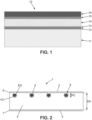
- a floor according to the prior art is illustrated schematically in the Fig. 1 .
- the floor 1 may be composed of an aluminum sandwich panel with a honeycomb 14 between two aluminum skins 13, 15.
- the sandwich panel is composed of an upper skin 15, a honeycomb core 14 and a lower skin 13. Above this sandwich panel is a floor covering 16, for example carpet.
- the sandwich panel comprises a heating film 12 encapsulating the heating elements.
- the heating film 12 is leaning against the lower skin of the panel 13, located between the latter and an insulating wool 11.
- the heating film 12 is self-adhesive, it is stuck to the skin of the panel 13 using a transfer adhesive.
- the data from the thermal behavior tests of heating panels incorporating heating films encapsulating the heating function show that the panels are sometimes subject to temperature inhomogeneity problems. Indeed, this is due to several factors including edge effects: heat losses on the edges of the panel due to the aluminum profiles thereof but also to numerous external factors such as mechanical constraints and variations in environmental conditions in the case of vehicles.
- temperature inhomogeneity problems can also be due to the concentration of heat around the heating films.
- the heating films have a homogeneous construction, thus leading to greater heating in the center of the film than at its ends, and therefore less homogeneity. Consequently, temperature peaks occur at the heating elements and reduce the heating power or lead to unnecessarily high energy consumption to reach the desired temperature in the passenger compartment.
- the shape of the films adapts poorly to the shapes of the panels, or not at all in the case of panels with more complex or irregular geometry.
- parts of the panels may be underheated or not heated at all, as they are not covered by these films. These panels have an insufficient coverage rate.
- heating films have many limitations. On the one hand, their cost remains high. On the other hand, as explained above, heating films have a standard architecture that is not very adaptable. Indeed, each change in panel geometry requires a change in the film architecture. In turn, any change in the internal architecture of the heating films (for example, the arrangement of the heating elements inside the film) requires a change in tooling, which implies additional costs and delays during the manufacturing process. Its production process is therefore not flexible, and therefore not very attractive.
- the core structure By adapting the core structure, it is possible to place the heating means, the single-conductor resistive cable, possibly by pressure, before adding the skins to make the panel.
- This new heating system will allow the heat to be selectively distributed through the panel skins.
- the core protects the heating means from the ambient environment, in particular from external temperature variations and mechanical shocks. Thus, heat losses at the edges of the panel are limited.
- the core also provides electrical insulation to prevent current leaks outside the panel, for example into the floor or partition of which the panel is part.
- Such a panel therefore allows for uniform and efficient heating while presenting a rigid structure, resistant to mechanical shocks and sufficiently thin.
- the manufacturing process of these panels is flexible because the shape of the circuit of the single-conductor resistive cable can be easily adapted by adapting the arrangement of the cavity(ies) according to the needs and application of the person skilled in the art.
- the cavities can be arranged so as to bypass an obstacle that could pass through the panel.
- a panel according to the invention has a coverage rate greater than 70%, preferably greater than 75%, more preferably greater than 80%, whereas a panel incorporating heating films rarely achieves a coverage rate greater than 66% (ratio between the surface covered by a heating film and the total surface of a panel).
- a single-conductor resistive heating cable imposes specific sizing constraints on its incorporation. Indeed, the thinner and longer a wire, the greater its electrical resistance.
- the inventors have noted that the uniformity of heating over the entire panel is improved with the increase in the heated area and, in order to ensure uniform heating, it is estimated, according to the invention, that the coverage rate is greater than 70%.
- the linear resistance of the cable can then be adjusted according to the supply voltage and the thermal power to be provided.
- homogeneous heating or homogeneous heat distribution we mean a good distribution of temperature on the panel, the temperature gradient between the hottest point and the coldest point of the panel is less than 7°C, preferably less than 5°C.
- cover rate is meant the ratio between the surface area covered by the single-conductor resistive heating cable and the total surface area of a panel.
- a panel according to the first aspect or obtained according to the second aspect in a railway vehicle as a panel heating by circulating an electric current in the single-conductor resistive heating cable.
- a panel according to the first aspect or obtained according to the second aspect in an aeronautical vehicle as a heating panel by circulation of an electric current in the single-conductor resistive heating cable.
- a floor or a partition comprising a panel according to the first aspect or obtained according to the second aspect.
- sandwich panel an assembly comprising at least three layers, in this case a structure having an intermediate layer, hereinafter called the core, between two external layers, hereinafter called the upper skin and the lower skin.
- the panel has a coverage rate greater than 70%, preferably greater than 75%, more preferably greater than 80%, or even greater than 85%.
- the panel has a coverage rate between 70% and 99%, preferably between 75% and 95%, more preferably between 80 and 90%.
- the thermally conductive upper skin ensures homogeneous radiation of the heat produced by the resistive cable and mechanical resistance while providing sealing properties.
- thermal conductor is a material characterized by its ability to diffuse heat in environments without macroscopic movement of matter. It is the ratio of thermal energy (amount of heat) transferred per unit of time (therefore homogeneous to a power, in watts) and surface area to the temperature gradient. Thermal conduction can occur quickly or slowly, or even very slowly.
- thermo insulator we mean a material which is defined in opposition to a “thermal conductor” material.
- the thermal conductivity of a thermally conductive layer of the panel is at least 5 times greater than the thermal conductivity of a thermally insulating layer of the panel, preferably at least 10 times greater.
- the material used for the upper skin can be chosen to distribute heat evenly. This material can, for example, have good heat conductivity and possess good thermal inertia. Good thermal inertia means a rapid rise in temperature and slow diffusion of heat by radiation.
- the upper skin may be a skin made of aluminum, steel, stainless steel, plastic (e.g. acrylonitrile butadiene styrene ABS, polycarbonate, etc.) or plywood or similar, or an assembly thereof obtained by thermosetting or thermoplastic bonding.
- the upper skin may be a single-ply or multi-ply composite material comprising glass, flax, carbon, basalt fibers or a mixture thereof, the constituent parts of said composite material being bound by thermosetting or thermoplastic resins. This list is not exhaustive and the person skilled in the art will be able to choose the appropriate material for the upper skin according to their needs.
- the upper skin may be made of aluminum, for example aluminum sheet or a composite material comprising glass fibers, or basalt fibers or a mixture thereof.
- the upper skin may have a thickness of at least 0.1 mm, preferably between 0.3 mm and 5 mm, preferably between 0.3 mm and 3 mm.
- the upper skin is an aluminum sheet having a thickness of at least 0.1 mm.
- the lower skin can be the same or different from the upper skin.
- the lower skin provides mechanical resistance and can also ensure homogeneous radiation of the heat produced by the resistive cable.
- the lower skin may be a skin made of aluminum, steel, stainless steel, plastic (for example, acrylonitrile butadiene styrene ABS, polycarbonate, etc.) or plywood, wood or the like, or an assembly thereof obtained by thermosetting or thermoplastic bonding.
- the lower skin may be a single-ply or multi-ply composite material comprising glass, flax, carbon, basalt fibers or a mixture thereof, the constituent parts of said composite material being bonded by thermosetting or thermoplastic resins. This list is not exhaustive and the person skilled in the art will be able to choose the appropriate material for the lower skin according to their needs.
- the lower skin can be made of aluminum, for example an aluminum sheet, thus ensuring the mechanical resistance of the panel.
- the lower skin may have a thickness of at least 0.1 mm, preferably between 0.3 mm and 5 mm, preferably between 0.3 mm and 3 mm.
- the lower skin is an aluminum sheet having a thickness of at least 0.1 mm.
- the lower skin can be thermally conductive or insulating.
- the core is disposed between the upper skin and the lower skin.
- the core has an upper face that can be adjacent to the thermally conductive upper skin and a lower face that can be adjacent to the lower skin.
- the term "core” means a layer incorporating the resistive cable, this layer being located between the upper skin and the lower skin of the panel, but the upper and lower faces of the core are not necessarily adjacent to each of the skins.
- the core can be rigid, resistant to bending.
- the panel may include other additional layers between the core and at least one of the upper and lower skins, such as an acoustic insulation layer.
- the panel may also include a repeating pattern between the two upper and lower skins, this repeating pattern being formed of one or more cores alternating with other additional layers.
- the core may also include one or more reinforcements extending between the upper and lower skins of the panel so as to enhance its mechanical properties. Indeed, thanks to its flexible manufacturing process, the cavity or cavities of the panel can be arranged so as to bypass the reinforcements. Such an architecture is difficult to achieve, or even impossible, with heating films according to the prior art.
- the core may be thermally insulating, made of a material having low thermal conductivity, i.e. capable of opposing the heat flow passing through it with a high thermal resistance.
- the thermal conductivity of the thermally conductive upper skin is at least 5 times greater than the thermal conductivity of the thermally insulating core, preferably at least 10 times greater.
- the core is chosen to limit heat loss generated by the single-core cable.
- the core plays a dual role: to limit heat loss and to contribute to the mechanical strength of the panel.
- the core may be in the form of a foam, for example a polymeric foam.
- the foam may have open or closed cells with homogeneous or variable density.
- the core can have good water and air tightness and good mechanical properties, particularly in bending.
- the core can protect against shocks and vibrations and also offers significant performance in sound insulation.
- the soul can be chosen so as to be able to form cavities either on its surface or in its core.
- the material constituting the core can be chosen from an aluminum or synthetic honeycomb (for example: aramid, polypropylene, etc.), rock wool, glass wool, polyurethane, polyethylene terephthalate (PET), polyethylene (PE), expanded polyethylene, polyetherimide (PEI), polyamide (PA), a core of bio-sourced origin, such as plywood, cork, bamboo, or mixtures thereof.
- an aluminum or synthetic honeycomb for example: aramid, polypropylene, etc.
- rock wool glass wool
- polyurethane polyethylene terephthalate (PET), polyethylene (PE), expanded polyethylene, polyetherimide (PEI), polyamide (PA), a core of bio-sourced origin, such as plywood, cork, bamboo, or mixtures thereof.
- PET polyethylene terephthalate
- PE polyethylene
- PEI polyethylene
- PA polyamide
- a core of bio-sourced origin such as plywood, cork, bamboo, or mixtures thereof.
- the core may have a density of between 1 and 1000 kg/ m3 , preferably between 20 and 350 kg/m3, more preferably between 80 and 150 kg/m3.
- the core comprises one or more cavities for housing the single-conductor resistive cable.
- the same cavity can house a single-conductor resistive cable along a single plane perpendicular to the panel, while the panel in its entirety can house one or more single-conductor resistive cables.
- the core may comprise one or more cavities provided opening onto one of its faces, the resistive heating cable being housed in one or more cavities.
- a face of the core having cavities provided may be adjacent to one of the skins of the panel.
- the core may include one or more cavities provided opening either on its upper face or on its lower face or on both its upper and lower faces.
- the core may include one or more cavities formed without opening onto any of its upper or lower faces.
- the cavity(ies) are sized and arranged so as to furrow the core and to produce a panel with a coverage rate greater than 70%.
- FIGS. 3 and 4 show simplified diagrams of a top view of a cavity path of a sandwich panel according to two embodiments.
- the resistive cable 5 winds along the path which comprises undulations along a direction of the panel, and in a homogeneous manner on the surface of the panel, namely that the period of the undulations of the path of constant value along a direction of the panel.
- a temperature gradient may appear during use during heating and following the direction of the corrugations, and due to edge losses; the temperature of the panel measured at the two edge zones of the panel may be lower than the temperature measured at an intermediate central zone.
- coverage density we mean the ratio of the length of the resistive cable per unit area of the sandwich panel.
- the temperature difference between the edge zones and the central portion is preferable to limit the temperature difference between the edge zones and the central portion to less than 4°C, preferably less than or equal to 2°C.
- the core has a section defined by its thickness EA.
- total thickness of the core EA is meant the thickness of the core measured on its untreated portion, as illustrated in the Figure 2 .
- the core has a total thickness EA and one or more cavities has a depth PC, the depth PC being less than the total thickness EA of the core.
- the depth PC corresponds to the distance between the throat entrance EG of a cavity and the bottom of a cavity FC.
- the depth of the cavity can be between 2 mm and 8 mm.
- the width of the cavity can be between 1 mm and 5.5 mm.
- the core may have a total thickness greater than 8 mm, preferably between 8 and 50 mm.
- One or more cavities have a depth. "Depth” means the depth of a cavity measured along a single plane perpendicular to the panel.
- a PC depth corresponds to the distance between the throat entrance EG of a cavity and the bottom of a cavity FC when the latter is arranged to open onto one of the faces of the core.
- groove entrance we mean the perimeter of a cavity when it is designed to open onto one of the faces of the core.
- the depth of such a cavity corresponds to the maximum distance from this cavity measured along a single plane perpendicular to the panel.
- each of them has a depth depending on the place on the core where it is located.
- the sum of the depths of the cavities along a single plane perpendicular to the panel remains less than the total thickness EA of the core.
- the sum of the depths of the cavities may exceed the total thickness EA of the core, as long as the sum of the depths of the cavities along a single plane perpendicular to the panel remains less than the total thickness EA of the core.
- a cavity depth of less than 1 mm would be insufficient to hold the heating medium in place. Conversely, a cavity depth that was too great in a single plane would create weak points in the core structure, which would affect the mechanical strength of the panels.
- the panels according to the invention are therefore sufficiently resistant to wear over time.
- the cable may extend along the length of the cavity or each of the cavities, the cavity or cavities being grooves having a PC depth section between 2 mm and 8 mm and a width between 1 mm and 5.5 mm.
- width we mean the maximum distance between the sides of a cavity measured along a plane parallel to the panel.
- the core may be arranged to form cavities opening onto its upper face by additive manufacturing or by etching.
- the cavities may be preformed grooves, for example by machining/etching or by hot wire cutting, in the foam before the integration of the cable or grooves formed during the integration of the cable under pressure, by pressing.
- the cavities are preformed grooves.
- the cross-section of the cavity may have a rounded, circular, rectangular, U-shaped, omega ⁇ , or any other shape allowing the heating means to be integrated.
- the shape of the cavities will be chosen by the person skilled in the art according to their needs so that they are sized to allow the heating means to be integrated. In the case of engraving, the person skilled in the art will know how to choose the shape of the head of the frieze adapted to obtain cavities adapted to their needs.
- the cavity(ies) have a groove entry width greater than the maximum cavity width. This allows for better retention of the cable inside the cavity(ies).
- the cavity(ies) may have a groove entry width greater than the diameter of the cable, said cavity being able to be sized to allow the insertion of the cable by elastically deforming the groove entry(s) of said cavity(ies).
- the resistive heating cable is a single-conductor resistive cable.
- the resistive heating cable can have a round cross-section.
- Resistive heating cable means a cable with a high resistance value in ohms, preferably between 0.1 ⁇ /m and 4000 ⁇ /m, preferably between 0.1 ⁇ /m and 1000 ⁇ /m or between 1 ⁇ /m and 4000 ⁇ /m.
- the diameter of the single-conductor resistive heating cable may be between 0.1 mm and 5 mm, preferably between 0.2 mm and 5 mm, preferably between 0.5 mm and 5 mm, 1 mm and 5 mm, preferably between 1.2 mm and 3 mm, or preferably between 0.1 mm and 1.5 mm, or preferably between 0.1 mm and 1 mm. Due to its reduced diameter, the cavities formed in the core to receive the single-conductor resistive heating cable have reduced sizes which do not affect the mechanical strength of the panel.
- the resistive cable winding along a path on the surface of the panel has a period of the path undulations of value D along a direction of the panel, the value D being between 25 and 80 mm, preferably between 35 and 70 mm.
- the minimum value of D allows to guarantee a minimum bending radius (D/2) so as not to alter the structure of the cable while above the upper limit, the homogeneity of the heating can be negatively impacted.
- the single-conductor resistive heating cable may comprise a resistive conductor and an electrically insulating jacket.
- the single-conductor resistive heating cable may contain inside a spiral system for generating heat from a power supply. electrical.
- the resistive conductor may be spirally arranged around an electrically non-conductive central core serving as mechanical support for said conductor.
- the electrically insulating jacket may have a thickness between 0.01 mm and 0.4 mm, preferably between 0.01 and 0.2 mm or between 0.2 mm and 0.4 mm. It may be made of a polymeric material, such as a fluorinated ethylene propylene resin.
- the heating means is not a double-conductor cable.
- Dual-core cables have a larger diameter than single-core cables, requiring an increase in the size of the cavities which would affect the mechanical resistance of the entire panel.
- Single-core heating cables are cables in which heat is released by the Joule-Lenz effect when the electric current passes through the heating core.
- the cable is designed so that a complete drop in the applied voltage occurs in the heating core, but the cable elements do not overheat beyond the permissible values. Cables of this type can have a heating core with a linear or spiral shape. This cable is connected at each end, hence the need to form a continuous circuit.
- the single-core cable can be supplied using a single-phase, two-phase or three-phase connection.
- the single-core cable has a single-phase connection, it is composed of a single conductor and the power supply is also single-phase.
- the cable will be installed in a serpentine pattern, necessarily making a round trip to the connection point.
- the upper face of the core is therefore engraved accordingly.
- Figure 6 This schematically illustrates a view of the upper face of the core.
- the heating means 5 is the single-conductor electrical cable which follows a serpentine circuit.
- the panel may comprise one or more single-conductor cables distributed over its surface.
- the description of the single-conductor cable above or below applies to each of the cables.
- the single-conductor cables may be identical or different, chosen so that each has the same resistance.
- An embodiment has been described with a single cable over the entire surface of the panel which may be suitable to a single-phase power supply.
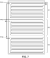
- the panel may include several cables, especially when the power supply is three-phase.
- the single-core cables will be mounted in a star configuration.
- the upper face of the core is therefore etched accordingly.
- Each cable will be connected to each of the phases on one side and to the other two cables on the other.
- the sum of the lengths of the 3 cables would be equal to the length of the cable that would have covered the surface of the panel alone, the lengths of each of the cables being equal.
- the connection point of the 3 cables will be connected to ground (neutral).
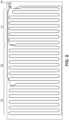
- FIG 8 illustrates an embodiment in which the panel comprises a three-phase delta supply, the connection being located outside the panel while the Figure 9 illustrates an embodiment in which the panel includes a three-phase delta supply, the three phases electrically connected to a connector 54 located within the panel.
- These example connections can also be advantageous in that they provide users with the freedom to adapt the connectors to the power source according to their needs.
- the heating means, the single-conductor resistive heating cable, is chosen so as to have a surface power of between 100 and 700 W/m 2 , preferably between 200 and 350 W/m 2 .
- the resistive heating cable can be connected to a power supply via a power cable, in particular one with a diameter larger than that of the cable.
- the connection can therefore be made by connectors.
- the resistive heating cable may have two ends. To ensure the connection, at least one stripped end of the resistive heating cable and one stripped end of a power cable may be connected by an electrical connector.
- a connector may be a mechanical crimping sleeve or a heat-shrinkable terminal consisting of a heat-shrinkable tube and a tin ring. This tube acts as a sleeve. By heating the sleeve, the tin melts to weld the two wires and the tube shrinks to ensure a seal.
- a stripped end of the resistive heating cable and a stripped end of a power cable can be mechanically crimped.
- the cable can be in direct contact with the core, inside the cavities, without adding any additional foil between the cable and the core. This helps limit unnecessary heat loss.
- the cable is not in direct contact with the upper skin.
- the panel may further comprise two adhesive layers adjacent to the top and bottom skins. These adhesive layers may connect the core to the skins of the panel.
- the adhesive layers are thermally conductive and can survive at temperatures above 60°C, preferably above 80°C, for example between 60°C and 160°C without their adhesive properties being negatively impacted.
- Adhesion can be achieved by various types of adhesives, such as glues.
- the adhesive may have a melting point of at least 60°C, preferably at least 65°C.
- the adhesive may have a melting point below 200°C, preferably at least 170°C.
- Adhesives effective at room temperature for "cold" pressing may also be used, for example two-component epoxy or polyurethane adhesives.
- the adhesive layers may comprise an adhesive selected from at least one of an olefin-based adhesive, a urethane-based adhesive, an acrylic-based adhesive, an epoxy-based adhesive, a polyamide-based adhesive, a phenolic adhesive, or a mixture thereof.
- the sandwich panel consists of a thermally conductive upper skin and a lower skin; a core arranged between the upper skin and the lower skin and a resistive heating cable, the resistive cable being single-conductor, the core comprising one or more cavities, the single-conductor resistive heating cable being housed in one or more cavities of the core and the coverage rate being greater than 70%.
- Each of the constituent elements of the panel can be the same as those described above.
- FIG. 2 schematically illustrates a panel 1 according to an embodiment in a perpendicular section.
- the skins 2 and 3 are arranged on either side of the upper and lower faces of the core 4, each connected by adhesive layers 6 and 7.
- the cable 5 is located at the upper face of the core 4, inside the cavities 8.
- the resistive cable winds around the panel with a period of path ripples of value D along a direction of the panel, as shown in Figure 5
- This value D is between 25 and 80 mm, preferably between 35 and 70 mm.
- the invention also relates to a floor or a partition comprising such a panel.
- the floor may further comprise acoustic insulation layers or surface covering layers.
- the term "upper skin” and, as opposed to "lower skin” is understood to mean the skin which is heated by the single-conductor cable when the sandwich panel is used as a floor (typically horizontally).
- the core comprises one or more cavities provided opening onto both the upper and lower faces of the core.
- the single-conductor resistive heating cable may therefore be housed in one or more cavities of the core on each of the upper and lower faces, the upper face being adjacent to the upper skin and the lower face being adjacent to the lower skin.
- the panel is typically arranged vertically: in such a case in the present application, reference may be made generally to a "first skin,” instead of "upper skin,” and to a "second skin,” instead of "lower skin.”
- pre-impregnated draping pre-impregnated draping
- LRI resin infusion Liquid Resin Infusion in English
- contact molding or contact lamination
- wet compression molding etc.
- the assembly can be hot-pressed for assembly. It must therefore withstand a temperature between 50°C and 170°C for 180 minutes.
- the skins correspond to fabrics pre-impregnated with a thermosetting or thermoplastic resin.
- the core can be impregnable, for example it can have through holes or can be porous, so as to allow the resin to pass through.
- the skins correspond to the unimpregnated fabrics.
- the core can be impregnable, for example it can have through holes or can be porous, so as to allow the passage of the resin.
- the invention relates to a floor comprising a panel according to the first aspect or obtained according to the above method.
- Every body emits infrared radiation.
- a thermal imaging camera captures this radiation and creates an image that displays the radiation intensity of different parts of the body. The hotter a body is, the higher the intensity of its radiation.
- the camera used is a TESTO camera.
- the images taken by this camera will be analyzed by suitable software. It is therefore possible to use this software to determine the hottest and coldest points of the body and also to plot a histogram illustrating a temperature gradient if one exists.
- thermocouples are used to measure the temperature at a specific point on the body. This device works by exploiting the Seebeck effect: the appearance of a potential difference following the temperature difference in contact between two conductive materials of different nature.
- a thermocouple consists of a hot junction (junction between two wires of different metals) which will be connected to a measuring device equivalent to a voltmeter. The junction point is the temperature detection point. Placing several thermocouples on different parts of the body allows a graph of temperature versus time to be drawn and thus to have an idea of the thermal behavior of the body. Thermocouples do not allow the distribution of heat to be visualized over the entire body but rather on a specific point.
- thermocouples for a total of 24 possible measurement points.
- the devices are then connected to measurement software to interpret the measurements.
- the electrical bench allows you to power the heating system (in this case, the resistive cable) but also to integrate additional controls into the assembly such as a switch or a probe.
- Heating is provided through the power supply by an electric bench. This heating allows the proper functioning of the heating means to be checked after gluing.
- Heating can be useful to see the maximum temperature a heating cable can reach. Heating generally requires a power supply and a ground connection.
- the homogeneity of the heat as well as the inertia of the heating system are evaluated during this test.
- Example 1 manufacturing a panel according to the invention
- Test 1 tests a panel according to Example 1 with an adhesive weight of 250g/m2.
- Test 2 tests a panel according to Example 1 with an adhesive weight of 250g/m2 but in which the resistive cable has not been added.
- MPa Essay Bending stress Flexural modulus
- MPa Breakup mode
- Tests 3 to 6 are carried out on panels according to Example 1.
- Test 3 tests a new panel with the cable heated to room temperature.
- Test 4 tests a new panel with the cable heated to 40°C.
- Test 5 tests an aged panel (carried out according to ISO 9142 following 7 type D3 cycles) whose cable is heated to room temperature.
- Test 6 tests an aged panel whose cable is heated to 40°C.
- a panel according to example 1 was tested.
- the cables are connected by a parallel circuit.
- the circuit is then supplied with a supply voltage of 230 V.
- thermocouple is placed in direct contact with the cable, then the aluminum sheet is placed on top and the temperature is recorded at different locations on the surface of the heating panel using thermocouples.
- the cable was first given time to reach its full potential (highest heating point), then the regulation was applied between 33.5°C and 34.5°C.
- the homogeneity of the heat generated by the heated floor was measured using two methods: thermocouples and a thermal imaging camera. The results show that the expected homogeneity is met.
Landscapes
- Resistance Heating (AREA)
Applications Claiming Priority (1)
| Application Number | Priority Date | Filing Date | Title |
|---|---|---|---|
| FR2311133A FR3154278A1 (fr) | 2023-10-16 | 2023-10-16 | Panneaux en sandwich integrant une fonction chauffante |
Publications (1)
| Publication Number | Publication Date |
|---|---|
| EP4543142A1 true EP4543142A1 (de) | 2025-04-23 |
Family
ID=89573993
Family Applications (1)
| Application Number | Title | Priority Date | Filing Date |
|---|---|---|---|
| EP24306705.5A Pending EP4543142A1 (de) | 2023-10-16 | 2024-10-16 | Sandwichplatten mit heizfunktion |
Country Status (2)
| Country | Link |
|---|---|
| EP (1) | EP4543142A1 (de) |
| FR (1) | FR3154278A1 (de) |
Citations (6)
| Publication number | Priority date | Publication date | Assignee | Title |
|---|---|---|---|---|
| FR2610098A1 (fr) | 1987-01-26 | 1988-07-29 | Alain K Jan | Panneaux sandwiches chauffants et (ou) refroidissants |
| US5740858A (en) | 1992-10-05 | 1998-04-21 | Ingram; Rex Anthony | Heating/cooling systems |
| EP1055087A1 (de) | 1998-02-11 | 2000-11-29 | Raymtech AB | Bodenheizanlage mit selbstregulierendem kabel |
| ITUD20090012A1 (it) * | 2009-01-19 | 2010-07-20 | Eurowood S P A | Pannello riscaldante e relativo procedimento di realizzazione |
| US20120234819A1 (en) | 2009-11-13 | 2012-09-20 | Berger Craig M | Multilayer structural heating panel |
| CN106714346A (zh) | 2016-12-26 | 2017-05-24 | 苏州卡尔玛智能暖居科技有限公司 | 一种双控温防覆盖的发热板系统 |
-
2023
- 2023-10-16 FR FR2311133A patent/FR3154278A1/fr active Pending
-
2024
- 2024-10-16 EP EP24306705.5A patent/EP4543142A1/de active Pending
Patent Citations (7)
| Publication number | Priority date | Publication date | Assignee | Title |
|---|---|---|---|---|
| FR2610098A1 (fr) | 1987-01-26 | 1988-07-29 | Alain K Jan | Panneaux sandwiches chauffants et (ou) refroidissants |
| US5740858A (en) | 1992-10-05 | 1998-04-21 | Ingram; Rex Anthony | Heating/cooling systems |
| EP1055087A1 (de) | 1998-02-11 | 2000-11-29 | Raymtech AB | Bodenheizanlage mit selbstregulierendem kabel |
| EP1055087B1 (de) * | 1998-02-11 | 2004-01-07 | Tyco Thermal Controls Nordic Aktiebolag | Bodenheizanlage mit selbstregulierendem kabel |
| ITUD20090012A1 (it) * | 2009-01-19 | 2010-07-20 | Eurowood S P A | Pannello riscaldante e relativo procedimento di realizzazione |
| US20120234819A1 (en) | 2009-11-13 | 2012-09-20 | Berger Craig M | Multilayer structural heating panel |
| CN106714346A (zh) | 2016-12-26 | 2017-05-24 | 苏州卡尔玛智能暖居科技有限公司 | 一种双控温防覆盖的发热板系统 |
Also Published As
| Publication number | Publication date |
|---|---|
| FR3154278A1 (fr) | 2025-04-18 |
Similar Documents
| Publication | Publication Date | Title |
|---|---|---|
| EP2842208B1 (de) | Verbindungskabelstrang für stromrückfluss und verfahren zur montage auf einem zusammengesetzten rumpfgerüst | |
| FR2790731A1 (fr) | Procede de simulation des flux thermiques externes absorbes en vol par les elements radiatifs exterieurs d'un engin spatial et engin spatial pour la mise en oeuvre de ce procede | |
| WO2014095991A1 (fr) | Dispositif d'interconnexion de cellules photovoltaiques a contacts en face arriere, et module comprenant un tel dispositif | |
| EP0778588B1 (de) | Flachkabel mit kleiner Marge | |
| WO2015150515A1 (fr) | Procédé et installation de réalisation d'une pièce en matériau composite | |
| EP3031726B1 (de) | Tragflächenelement für Luftfahrzeug | |
| FR3025368A1 (fr) | Garnitures d'encoches de rotors | |
| EP4104279B1 (de) | Elektrisch und thermisch leitfähiges element und verfahren zur herstellung eines solchen elements | |
| EP1269604A1 (de) | Elektrischer verbinder mit mehrfachkontaktelementen und drehende elektrische maschine mit einem solchen verbinder | |
| EP0926925A1 (de) | Heizpanneel aus Kohlefasern und Verfahren zu dessen Herstellung | |
| FR3154278A1 (fr) | Panneaux en sandwich integrant une fonction chauffante | |
| EP2623909B1 (de) | Fotovoltaikpaneel mit Wärmerückgewinnung | |
| EP4358657A1 (de) | Harzfolie | |
| EP0081154B1 (de) | Verwendung eines Wickelbandes für die primäre Isolation von Leitern | |
| EP1605474B1 (de) | Kabel mit mehreren isolierten Leitern in einem Mantel und Herstellungsverfahren des Kabels. | |
| EP4541137A1 (de) | Verfahren zur erlangung einer fussbodenheizung für fahrzeuge und fussbodenheizung für fahrzeuge | |
| FR3054947A1 (fr) | Structure chauffante | |
| FR3136695A1 (fr) | Procede d’obtention d’un plancher chauffant pour vehicules, et plancher chauffant pour vehicules | |
| CA2871224C (fr) | Procede de connexion de conducteurs d'une nappe souple de liaison equipotentielle, ainsi que outil de sertissage, connecteurs et harnais equipe de tels connecteurs | |
| FR3168088A1 (fr) | Procédé de fabrication d’un stator pour machine électrique tournante d’aéronef | |
| FR2947665A1 (fr) | Cable comprenant des moyens de detection aptes a detecter la presence d'un corps electriquement conducteur exterieur au cable | |
| EP1260992B1 (de) | Verfahren zur Herstellung eines elektrischen Verbundisolators mit einer Aussenschicht und mindestens einer optischen Faser, die miteinander kompatibel sind | |
| FR3163510A1 (fr) | Stator pour machine électrique tournante d’aéronef | |
| FR3029062B1 (fr) | Dispositif conducteur destine a etre monte en surface des pieces en materiaux composites et procede pour realiser un tel dispositif | |
| WO2016034800A1 (fr) | Jauge de carburant |
Legal Events
| Date | Code | Title | Description |
|---|---|---|---|
| PUAI | Public reference made under article 153(3) epc to a published international application that has entered the european phase |
Free format text: ORIGINAL CODE: 0009012 |
|
| STAA | Information on the status of an ep patent application or granted ep patent |
Free format text: STATUS: THE APPLICATION HAS BEEN PUBLISHED |
|
| AK | Designated contracting states |
Kind code of ref document: A1 Designated state(s): AL AT BE BG CH CY CZ DE DK EE ES FI FR GB GR HR HU IE IS IT LI LT LU LV MC ME MK MT NL NO PL PT RO RS SE SI SK SM TR |
|
| STAA | Information on the status of an ep patent application or granted ep patent |
Free format text: STATUS: REQUEST FOR EXAMINATION WAS MADE |
|
| 17P | Request for examination filed |
Effective date: 20251015 |
|
| RAP3 | Party data changed (applicant data changed or rights of an application transferred) |
Owner name: KELOX RAILWAY FRANCE |