EP4542593A2 - Abstimmbarer induktor und verfahren zur herstellung eines abstimmbaren induktors - Google Patents
Abstimmbarer induktor und verfahren zur herstellung eines abstimmbaren induktors Download PDFInfo
- Publication number
- EP4542593A2 EP4542593A2 EP24203047.6A EP24203047A EP4542593A2 EP 4542593 A2 EP4542593 A2 EP 4542593A2 EP 24203047 A EP24203047 A EP 24203047A EP 4542593 A2 EP4542593 A2 EP 4542593A2
- Authority
- EP
- European Patent Office
- Prior art keywords
- leg
- winding
- core
- flux
- tunable inductor
- Prior art date
- Legal status (The legal status is an assumption and is not a legal conclusion. Google has not performed a legal analysis and makes no representation as to the accuracy of the status listed.)
- Pending
Links
Images




Classifications
-
- H—ELECTRICITY
- H01—ELECTRIC ELEMENTS
- H01F—MAGNETS; INDUCTANCES; TRANSFORMERS; SELECTION OF MATERIALS FOR THEIR MAGNETIC PROPERTIES
- H01F29/00—Variable transformers or inductances not covered by group H01F21/00
- H01F29/14—Variable transformers or inductances not covered by group H01F21/00 with variable magnetic bias
-
- H—ELECTRICITY
- H01—ELECTRIC ELEMENTS
- H01F—MAGNETS; INDUCTANCES; TRANSFORMERS; SELECTION OF MATERIALS FOR THEIR MAGNETIC PROPERTIES
- H01F29/00—Variable transformers or inductances not covered by group H01F21/00
- H01F29/02—Variable transformers or inductances not covered by group H01F21/00 with tappings on coil or winding; with provision for rearrangement or interconnection of windings
- H01F29/025—Constructional details of transformers or reactors with tapping on coil or windings
-
- H—ELECTRICITY
- H01—ELECTRIC ELEMENTS
- H01F—MAGNETS; INDUCTANCES; TRANSFORMERS; SELECTION OF MATERIALS FOR THEIR MAGNETIC PROPERTIES
- H01F17/00—Fixed inductances of the signal type
- H01F17/04—Fixed inductances of the signal type with magnetic core
-
- H—ELECTRICITY
- H01—ELECTRIC ELEMENTS
- H01F—MAGNETS; INDUCTANCES; TRANSFORMERS; SELECTION OF MATERIALS FOR THEIR MAGNETIC PROPERTIES
- H01F27/00—Details of transformers or inductances, in general
- H01F27/34—Special means for preventing or reducing unwanted electric or magnetic effects, e.g. no-load losses, reactive currents, harmonics, oscillations, leakage fields
- H01F27/38—Auxiliary core members; Auxiliary coils or windings
-
- H—ELECTRICITY
- H01—ELECTRIC ELEMENTS
- H01F—MAGNETS; INDUCTANCES; TRANSFORMERS; SELECTION OF MATERIALS FOR THEIR MAGNETIC PROPERTIES
- H01F3/00—Cores, Yokes, or armatures
- H01F3/10—Composite arrangements of magnetic circuits
- H01F3/14—Constrictions; Gaps, e.g. air-gaps
-
- H—ELECTRICITY
- H01—ELECTRIC ELEMENTS
- H01F—MAGNETS; INDUCTANCES; TRANSFORMERS; SELECTION OF MATERIALS FOR THEIR MAGNETIC PROPERTIES
- H01F3/00—Cores, Yokes, or armatures
- H01F3/10—Composite arrangements of magnetic circuits
- H01F2003/106—Magnetic circuits using combinations of different magnetic materials
-
- H—ELECTRICITY
- H01—ELECTRIC ELEMENTS
- H01F—MAGNETS; INDUCTANCES; TRANSFORMERS; SELECTION OF MATERIALS FOR THEIR MAGNETIC PROPERTIES
- H01F29/00—Variable transformers or inductances not covered by group H01F21/00
- H01F29/14—Variable transformers or inductances not covered by group H01F21/00 with variable magnetic bias
- H01F2029/143—Variable transformers or inductances not covered by group H01F21/00 with variable magnetic bias with control winding for generating magnetic bias
Definitions
- the present disclosure relates to inductors and, in particular, to the realization of tunable inductors.
- Inductors are passive components that can be critical to power handling in power converter topologies such as, for example, DC-DC conversion, AC-DC conversion, and the like. Though some tunable inductors have been implemented in a wide variety of applications, the basic mechanism of achieving tunability of some inductors is associated with several disadvantages.
- a tunable inductor including: a core having a closed shape and including a first leg, a second leg, and a third leg between the first leg and the second leg; a first winding wound around the first leg; a second winding wound around the second leg; a third winding wound around the third leg; and a first magnetoelectric material coupled to the core.
- the first winding is coupled to a first controller configured to provide DC power to the first winding, and the first winding is configured to generate a DC flux in a DC flux path in response to the DC power, the DC flux path passing through the first magnetoelectric material.
- the second winding is coupled to the first controller and is configured to generate the DC flux in response to the DC power.
- the third winding is coupled to an AC power source configured to provide AC power to the third winding, and the third winding is configured to generate AC flux in an AC flux path in response to the AC power, the AC flux path passing through the first magnetoelectric material.
- the first magnetoelectric material may be coupled to a portion of the core that is not wound by the first winding, the second winding, or the third winding.
- the portion of the core may include: an upper portion of the core, where the upper portion is between the first leg and the second leg; or a lower portion of the core, where the lower portion is between the first leg and the second leg.
- the tunable inductor may further include: a second magnetoelectric material coupled to the core, where: the DC flux path further may pass through the second magnetoelectric material; the AC flux path may further pass through the second magnetoelectric material; and the second magnetoelectric material may be coupled to a portion of the core that is not wound by the first winding, the second winding, or the third winding.
- the DC flux path may pass through the first leg, the second leg, the third leg, the first magnetoelectric material, and the second magnetoelectric material;
- the AC flux path may pass through the third leg, the first magnetoelectric material, and the first leg in a counterclockwise direction; and the AC flux path may pass through the third leg, the second magnetoelectric material, and the second leg in a clockwise direction.
- the tunable inductor may further include: a second controller configured to control one or more properties of the first magnetoelectric material, where the second controller is configured to control the one or more properties based on at least one of: a reluctance of a first branch of the tunable inductor, the first branch including the first leg, the third leg, and a first upper portion between the first leg and the third leg; and a second reluctance of a second branch of the tunable inductor, the second branch including the second leg, the third leg, and a second upper portion between the second leg and the third leg.
- the tunable inductor may be absent an air gap.
- a tunable inductor including: a core having a closed shape and including a first leg, a second leg, and a third leg between the first leg and the second leg; a first winding wound around the first leg; and a second winding wound around the second leg, where a first winding direction of an upper half of the second winding is opposite to a second winding direction of a lower half of the second winding.
- the first winding is coupled to a controller configured to provide DC power to the first winding, and the first winding is configured to generate a DC flux in a DC flux path in response to the DC power, the DC flux path passing through the first leg, the third leg, and the second leg.
- the second winding is coupled to an AC power source configured to provide AC power to the second winding, and the second winding is configured to generate AC flux in a plurality of AC flux paths in response to the AC power.
- a first AC flux path of the plurality of AC flux paths passes through an upper portion of the core and returns via a path perpendicular to the third leg, and a second AC flux path of the plurality of AC flux paths passes through a lower portion of the core and returns via a second path perpendicular to the third leg.
- the tunable inductor may further include: a first magnetoelectric material coupled to a portion of the core that is not wound by the first winding or the second winding, where the DC flux path may pass through the first magnetoelectric material, and the first AC flux path may pass through the first magnetoelectric material.
- the portion of the core may include: the upper portion of the core, where the upper portion is between the first leg and the second leg; or the lower portion of the core, where the lower portion is between the first leg and the second leg.
- the tunable inductor may further include: a second magnetoelectric material coupled to a second portion of the core that is not wound by the first winding or the second winding, where the DC flux path further may pass through the second magnetoelectric material and the first AC flux path or the second AC flux path may pass through the second magnetoelectric material.
- a first distance between the first leg and the third leg may be less than a second distance between the second leg and the third leg.
- the tunable inductor may further include: a controller configured to control one or more properties of one or more magnetoelectric materials coupled to portion of the core that is not wound by the first winding or the second winding, where the controller is configured to control the one or more properties based on one or more target properties of the tunable inductor.
- the tunable inductor may be absent an air gap.
- a tunable inductor including: a core having a closed shape and including a first leg and a second leg; a first winding wound around the first leg; and a second winding wound around the second leg, where a first winding direction of an upper half of the second winding is opposite to a second winding direction of a lower half of the second winding.
- the first winding is coupled to a controller configured to provide DC power to the first winding, and the first winding is configured to generate a DC flux in a DC flux path in response to the DC power, the DC flux path passing through the first leg and the second leg.
- the second winding is coupled to an AC power source configured to provide AC power to the second winding, and the second winding is configured to generate AC flux in a plurality of AC flux paths in response to the AC power.
- a first AC flux path of the plurality of AC flux paths passes through an upper leg of the core and returns via a path perpendicular or almost perpendicular to the first leg and the second leg.
- a second AC flux path of the plurality of AC flux paths passes through a lower leg of the core and returns via a second path perpendicular or almost perpendicular to the first leg and the second leg.
- the tunable inductor may further include a first magnetoelectric material coupled to a portion of the core that is not wound by the first winding or the second winding, where the DC flux path may pass through the first magnetoelectric material, and the first AC flux path may pass through the first magnetoelectric material.
- the portion of the core may include an upper portion of the core, where the upper portion is between the first leg and the second leg, or a lower portion of the core, where the lower portion is between the first leg and the second leg.
- the tunable inductor may further include a second magnetoelectric material coupled to a second portion of the core that is not wound by the first winding or the second winding, where the DC flux path further may pass through the second magnetoelectric material, and the first AC flux path or the second AC flux path may pass through the second magnetoelectric material.
- the tunable inductor may further include a controller configured to control one or more properties of one or more magnetoelectric materials coupled to portion of the core that is not wound by the first winding or the second winding, where the controller is configured to control the one or more properties based on one or more target properties of the tunable inductor.
- the tunable inductor may be absent an air gap.
- an inductor having a tunable inductance may be associated with an increase in physical inductor size and an unbalanced flux distribution in the core material associated with the inductor.
- Other disadvantages associated with some tunable inductors include high back-electromotive force (EMF) voltages induced in the control coil and associated power supply, and further, high ripple current spikes may be induced on the control side.
- EMF back-electromotive force
- Other example disadvantages associated with some tunable inductors include a relatively narrow range of tunability and a relatively slow control of the inductor characteristics.
- hybrid approaches are described that support the realization of a tunable inductor.
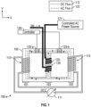
- FIG. 1 is an example of a tunable inductor 100-a in accordance with one or more embodiments of the present disclosure.
- the tunable inductor 100-a includes a core 105.
- the tunable inductor 100-a may be referred to as a 'soft' tunable inductor 100, and the core 105 may be referred to as a 'soft' magnetic core, in that the core 105 is formed of material having soft magnetic properties.
- the core 105 may be magnetized in response to voltages across windings (e.g., first winding 110, second winding 115, and/or third winding 120) of the tunable inductor 100-a.
- the core 105 is a quadrilateral shaped, but aspects of the tunable inductor 100-a are not limited thereto.
- the core 105 may be an enclosed core of any suitable shape (e.g., a closed shape, quadrilateral, rectangular, square, circular, or the like) or dimension supportive of the techniques of inductor tuning as described herein.
- Aspects of the present disclosure support the implementation of one or more types of cross-sectional shapes and geometries such as, for example, substantially rectangular, circular, or oval shapes.
- the core 105 includes a first leg 101, a second leg 102, and a third leg 103 between the first leg 101 and the second leg 102.
- the first leg 101, the second leg 102, and the third leg 103 are parallel to one another, but aspects of the core 105 are not limited thereto.
- the tunable inductor 100-a includes a first winding 110 wound around the first leg 101 and a second winding 115 wound around the second leg 102.
- the first winding 110 and the second winding 115 are coupled to a first controller 111.
- the first controller 111 may be, for example, a direct current (DC) controller capable of providing DC power to the first winding 110 and the second winding 115.
- DC direct current
- the first winding 110 and the second winding 115 In response to the DC power, the first winding 110 and the second winding 115 generate a DC flux 112 (also referred to herein as a magnetic flux or magnetic field resulting from the DC power provided to the first winding 110 and/or the second winding 115), and the DC flux 112 flows through the core 105 according to a DC flux path (indicated by arrows) illustrated at FIG. 1 .
- the first winding 110 and second winding 115 may also be referred to herein as DC coils.
- the tunable inductor 100-a includes a third winding 120 wound around the third leg 103.
- the third winding 120 is coupled to an AC power source 121 providing AC power to the third winding 120.
- the third winding 120 generates AC flux 122 (also referred to herein as a magnetic flux or magnetic field resulting from the AC power provided to the third winding 120), and the AC flux 122 flows through the core 105 according to an AC flux path (indicated by arrows) illustrated at FIG. 1 .
- the third winding 120 may also be referred to as an AC coil.
- the techniques described herein incorporate magnetoelectric materials 125 at the tunable inductor 100, and the magnetoelectric materials 125 have an adjustable permeability supportive of balancing the flux in the various paths of the core 105.
- the tunable inductor 100-a includes a first magnetoelectric material 125-a and a second magnetoelectric material 125-b coupled to the core 105.
- the first magnetoelectric material 125-a and the second magnetoelectric material 125-b may be coupled to portions of the core 105 that are not wound by the first winding 110, the second winding 115, or the third winding 120.
- the first magnetoelectric material 125-a is coupled to an upper portion of the core 105, between the first leg 101 and the third leg 103
- the second magnetoelectric material 125-b is coupled to an upper portion of the core 105, between the second leg 102 and the third leg 103.
- the first magnetoelectric material 125-a and the second magnetoelectric material 125-b may be coupled to any suitable location on the core 105 such that the AC flux path and DC flux paths described herein pass through the first magnetoelectric material 125-a and second magnetoelectric material 125-b.
- the first magnetoelectric material 125-a may be coupled to the upper portion or a lower portion of the core 105, between the first leg 101 and the third leg 103
- the second magnetoelectric material 125-b may be coupled to the upper portion or a lower portion of the core 105, between the second leg 102 and the third leg 103.
- the AC flux path and DC flux paths pass through the first magnetoelectric material 125-a and the second magnetoelectric material 125-b.
- the DC flux path passes through the first leg 101, the second leg 102, the third leg 103, the first magnetoelectric material 125-a, and the second magnetoelectric material 125-b.
- the AC flux path passes through the third leg 103, the first magnetoelectric material 125-a, and the first leg 101 in a counterclockwise direction
- the AC flux path passes through the third leg 103, the second magnetoelectric material 125-b, and the second leg 102 in a clockwise direction.
- the tunable inductor 100-a may include or be coupled to a second controller 126 (also referred to herein as a tuning circuit) configured to control one or more properties of the first magnetoelectric material 125-a and the second magnetoelectric material 125-b.
- the second controller 126 may generate a control signal associated with controlling properties (e.g., permeability) of the first magnetoelectric material 125-a and/or second magnetoelectric material 125-b, which in turn impacts one or more properties of the tunable inductor 100.
- control signal may be a control voltage which, when applied by the second controller 126 to a magnetoelectric material 125 (e.g., first magnetoelectric material 125-a, second magnetoelectric material 125-b), establishes an induced internal magnetic field at the magnetoelectric material 125.
- a magnetoelectric material 125 e.g., first magnetoelectric material 125-a, second magnetoelectric material 125-b
- the second controller 126 may control the properties based on a first reluctance R of a first branch of the tunable inductor 100-a and/or a second reluctance R of a second branch of the tunable inductor 100.
- the first branch includes the first magnetoelectric material 125-a (e.g., a branch including the first leg 101, the third leg 103, and a first upper portion of the core 105 between the first leg 101 and the third leg 103)
- the second branch includes the second magnetoelectric material 125-b (e.g., a branch including the second leg 102, the third leg 103, and a second upper portion of the core 105 between the second leg 102 and the third leg 103).
- the magnetoelectric materials 125 have properties of adjustable permeability with applied electric field
- the techniques described herein support manipulation of the magnetic flux (e.g., the amplitude of the magnetic flux) in each magnetic flux path.
- the implementation of the magnetoelectric materials 125 and control of the properties of the magnetoelectric materials 125 support an increased number of capabilities in tunable inductors.
- the example tunable inductor 100-a and the techniques described herein support controlled rebalancing of uneven AC flux distribution through the balancing the reluctance R of branches (e.g., two branches) of the tunable inductor 100-a via the first magnetoelectric material 125-a and second magnetoelectric material 125-b when applying a voltage to tune permeability.
- Tuning the permeability of the first magnetoelectric material 125-a and/or second magnetoelectric material 125-b cancels the induced back-EMF AC voltage (associated with the AC flux and the third winding 120) on the first winding 110 and second winding 115.
- balancing the reluctance R of branches of the tunable inductor 100-a may be implemented by applying a voltage at the first magnetoelectric material 125-a and/or the second magnetoelectric material 125-b to tune the rated voltage and magnetic permeability ( ⁇ r ) of the tunable inductor 100.
- the tuning may effectively cancel the induced back-EMF AC voltage (also referred to herein as uncancelled high back-EMF voltage) and high ripple current on the first winding 110, the second winding 115, and the control path associated with the tunable inductor 100.
- the second controller 126 may include sensing circuitry ((not illustrated) capable of sensing the AC voltages of the first winding 110 and second winding 115 or the magnetic flux of the two branches (e.g., AC flux 122) described herein.
- the sensed difference of the two AC winding voltages e.g., the AC voltages of the first winding 110 and second winding 115
- the difference of the magnetic fluxes e.g., AC flux 122
- a closed-loop feedback controller such as, for example, a proportional-integral-derivative (PID) controller, a proportional-resonant (PR) controller, or a combination of the PID controller and the PR controller.
- PID proportional-integral-derivative
- PR proportional-resonant
- the closed-loop feedback controller may be configured to adaptively tune the output voltage of the second controller 126 for rebalancing the reluctance R and AC flux of the branches of the tunable inductor 100-a.
- the AC voltage sensing described herein supports indirect sensing of the AC voltages of the first winding 110 and the second winding 115, as the AC voltage of each winding is proportional to the AC flux flowing through the corresponding branch of the tunable inductor 100-a.
- the principles described herein in association with the controlled permeability of the magnetoelectric materials 125 (and thereby, for example, the controlled rebalancing of uneven AC flux distribution and controlled balancing of reluctance R) at the tunable inductor 100-a may support implementations capable of omitting the air gap 130 in the third leg 103.
- the example principles and techniques described herein support implementations of tunable inductors which may omit a center leg of EE shaped cores and eliminate the center leg in gapless cores, examples of which are later described herein.
- the example dimensions, shapes, and quantities of the magnetoelectric materials 125 provided herein are not limited to the example embodiments described herein.
- the magnetoelectric materials 125 may be of any suitable shape, size, and quantity of instances supportive of the techniques for the controlled permeability of the magnetoelectric materials 125, the controlled rebalancing of uneven AC flux distribution, and the controlled balancing of reluctance R at the tunable inductor 100-a as described herein.
- FIG. 2 is an example of a tunable inductor 100-b in accordance with one or more embodiments of the present disclosure.
- the tunable inductor 100-b includes aspects of tunable inductor 100-a, and repeated descriptions of like elements are omitted for brevity. Further, so as not to distract from the additional and/or alternative features described in FIG. 2 , aspects of the first controller 111, AC power source 121, and second controller 126 (of FIG. 1 ) are not illustrated.
- the use of the magnetoelectric materials 125 supports implementations of a tunable inductor 100-b in which the air gap 130 (of FIG. 1 ) in the third leg 103 may be omitted.
- the tunable inductor 100-b supports a reduction in leakage flux, eddy current loss, and electromagnetic noise that could otherwise be introduced at the air gap 130.
- the example aspects described herein may be applied to other magnetic winding structures for tunable inductor implementation.
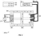
- FIG. 3 is an example of a tunable inductor 300-a in accordance with one or more embodiments of the present disclosure.
- the tunable inductor 300-a may include aspects of other example tunable inductors (e.g., tunable inductor 100-a, tunable inductor 100-b) described herein, and repeated descriptions of like elements are omitted for brevity.
- the tunable inductor 300-a illustrates an example implementation of reversely wound windings supportive of eliminating an air gap in tunable inductors (e.g., implementation of a gapless tunable inductor).
- the example configuration and features of the tunable inductor 300-a described herein support adjustment of magnetic flux in the tunable inductor 300-a and implementation without an air gap (e.g., an air gap 130 as in FIG. 1 ).
- tunable inductor 300-a includes a core 305.
- the core 305 includes a first leg 301, a second leg 302, and a third leg 303 between the first leg 301 and the second leg 302.
- the tunable inductor 300-a includes a first winding 310 wound around the first leg 301.
- the first winding 310 is coupled to a controller 311 providing DC power to the first winding 310.
- the first winding 310 generates a DC flux 312 in a DC flux path in response to the DC power, and the DC flux path (indicated by arrows) passing through the first leg 301, the third leg 303, and the second leg 302.
- the tunable inductor 300-a includes a second winding 320 wound around the second leg 302.
- a winding direction of the first winding 310 is opposite a second winding direction of the second winding 320.
- the second winding 320 is coupled to an AC power source 321 providing AC power to the second winding 320.
- the second winding 320 generates AC flux 322 in a plurality of AC flux paths (indicated by arrows) in response to the AC power.
- a first AC flux path of the plurality of AC flux paths may pass through an upper portion of the core 305 (e.g., in a direction toward the first winding 310) and returns via a path perpendicular to the third leg 303.
- a second AC flux path of the plurality of AC flux paths may pass through a lower portion of the core 305 and returns via a second path through the air perpendicular (e.g., substantially or almost perpendicular) to the third leg 303.
- other AC flux paths of the plurality of AC flux paths may pass through part or the entirety of the upper portion or the lower portion and return via a path through the air perpendicular (e.g., substantially or almost perpendicular) to the third leg 303.
- the return path may be substantially parallel to a horizontal axis (e.g., the X-axis in FIG. 3 ) of the tunable inductor 300-a.
- FIG. 4 is an example of a tunable inductor 300-b in accordance with one or more embodiments of the present disclosure.
- the tunable inductor 300-b includes aspects of tunable inductor 300-a, and repeated descriptions of like elements are omitted for brevity. Further, so as not to distract from the additional and/or alternative features described in FIG. 3 , aspects of the first controller 311 and AC power source 321 (of FIG. 3 ) are not illustrated.
- the tunable inductor 300-b may include one or more magnetoelectric materials 325 to further balance magnetic flux (e.g., DC flux 312, AC flux 322).
- the magnetoelectric materials 325 have an adjustable permeability supportive of balancing the flux in the various paths of the core 305.
- the tunable inductor 300-b includes a first magnetoelectric material 325-a and a second magnetoelectric material 325-b coupled to the core 305.
- the tunable inductor 300-b includes a second controller 326 configured to control one or more properties of magnetoelectric materials 325.
- the second controller 326 may control the properties based on one or more target properties of the tunable inductor 300.
- each of the first magnetoelectric material 325-a and the second magnetoelectric material 325-b is coupled to a portion of the core 305 that is not wound by the first winding 310 or the second winding 320.
- the first magnetoelectric material 325-a is coupled to an upper portion of the core 305, between the first leg 301 and the second leg 302, and the second magnetoelectric material 325-b is coupled to a lower portion of the core 305, between the first leg 301 and the second leg 302.
- the techniques described herein support rebalancing of the unbalanced AC flux and reluctance R.
- first magnetoelectric material 325-a and the second magnetoelectric material 325-b may be coupled to any suitable location on the core 305 such that the AC flux path and DC flux paths described herein pass through the first magnetoelectric material 325-a and second magnetoelectric material 325-b.
- the first magnetoelectric material 325-a may be coupled to a first upper portion of the core 305 (e.g., between the first leg 301 and the second leg 302)
- the second magnetoelectric material 325-b may be coupled to a second upper portion of the core 305 (e.g., also between the first leg 301 and the second leg 302, or between the second leg 302 and the third leg 303).
- the first magnetoelectric material 325-a may be coupled to a first lower portion of the core 305 (e.g., between the first leg 301 and the second leg 302)
- the second magnetoelectric material 325-b may be coupled to a second lower portion of the core 305 (e.g., also between the first leg 301 and the second leg 302, or between the second leg 302 and the third leg 303).
- a first AC flux path of the plurality of AC flux paths may pass through the first magnetoelectric material 325-a
- a second AC flux path of the plurality of AC flux paths may pass through the second magnetoelectric material 325-b
- the DC flux path passes through the first magnetoelectric material 325-a and the second magnetoelectric material 325-b.
- an AC flux path could pass through a single or multiple magnetoelectric materials 325.
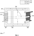
- FIG. 5 is an example of a tunable inductor 300-c in accordance with one or more embodiments of the present disclosure.
- the tunable inductor 300-c may include aspects of other example tunable inductors (e.g., tunable inductor 300-a, tunable inductor 300-b) described herein, and repeated descriptions of like elements are omitted for brevity. Further, so as not to distract from the additional and/or alternative features described in FIG. 5 , aspects of the first controller 311 and AC power source 321 (of FIG. 3 ) are not illustrated.
- the tunable inductor 300-c illustrates an example implementation of modifying the geometry of the core 305 supportive of mitigating flux unbalance and eliminating an air gap in tunable inductors (e.g., implementation of a gapless tunable inductor).
- aspects of the present disclosure support adjusting the placement of the third leg 303 in support of mitigating flux imbalance and implementing the tunable inductor 300-c without an air gap.
- a first distance between the first leg 301 and the third leg 303 is less than a second distance between the second leg 302 and the third leg 303.
- a majority of the AC flux 322 out of the AC winding 320 may return through the space 304 in the window area enclosed by the third leg 303 and the second leg 302, instead of flowing through the DC winding 310.
- the return of the majority of the AC flux 322 through the space 304 reduces the total AC flux 322 through the winding 310 and the flux imbalance associated with the upper and lower branch of tunable inductor 300-c (e.g., the flux imbalance associated with the flow of the AC flux 322 through the upper branch and lower branch).
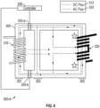
- FIG. 6 is an example of a tunable inductor 300-d in accordance with one or more embodiments of the present disclosure.
- the tunable inductor 300-d may include aspects of other tunable inductors (e.g., tunable inductor 300-a through tunable inductor 300-d) described herein, and repeated descriptions of like elements are omitted for brevity. Further, so as not to distract from the additional and/or alternative features described in FIG. 6 , aspects of the first controller 311 and AC power source 321 (of FIG. 3 ) are not illustrated.
- the tunable inductor 300-d may include one or more magnetoelectric materials 325 to further balance the AC magnetic flux (e.g., AC flux 322).
- the tunable inductor 300-d includes a first magnetoelectric material 325-a and a second magnetoelectric material 325-d coupled to the core 305.
- the tunable inductor 300-d includes a second controller 326 configured to control one or more properties of magnetoelectric materials 325.
- the second controller 326 may control the properties based on one or more target properties of the tunable inductor 300.
- each of the first magnetoelectric material 325-a and the second magnetoelectric material 325-d is coupled to a portion of the core 305 that is not wound by the first winding 310 or the second winding 320.
- the first magnetoelectric material 325-a is coupled to an upper portion of the core 305, between the first leg 301 and the second leg 302 (e.g., between first leg 301 and third leg 303), and the second magnetoelectric material 325-d is coupled to a lower portion of the core 305 between the first leg 301 and the second leg 302 (e.g., between first leg 301 and third leg 303).
- first magnetoelectric material 325-a and the second magnetoelectric material 325-d may be coupled to any suitable location on the core 305 such that the AC flux path and DC flux paths described herein pass through the first magnetoelectric material 325-a and second magnetoelectric material 325-d.
- FIG. 7 is an example of a tunable inductor 700 in accordance with one or more embodiments of the present disclosure.
- the tunable inductor 700 may include aspects of other example tunable inductors (e.g., tunable inductor 100-a, tunable inductor 100-b, tunable inductor 300-a through tunable inductor 300-d) described herein, and repeated descriptions of like elements are omitted for brevity.
- the tunable inductor 700 illustrates an example implementation using reversely wound windings (e.g., as described with reference to FIGS. 3 through 6 ) and one or more magnetoelectric materials 725 (e.g., as described with reference to FIGS. 2 , 4 , and 6 ) for balancing magnetic flux and eliminating an air gap in tunable inductors (e.g., implementation of a gapless tunable inductor).
- the example configuration and features of the tunable inductor 700 described herein further support tunable inductor implementations without central limb (e.g., without third leg 103 of FIGS. 1 and 2 , without third leg 303 of FIGS. 3 through 6 ) and using magnetoelectric materials 725 to balance the flux distribution of the gapless tunable inductors.
- the tunable inductor 700 includes a core 705 including a first leg 701 and a second leg 702.
- the tunable inductor 700 includes a first winding 710 wound around the first leg 701 and a second winding 715 wound around the second leg 702.
- winding direction of the upper half of the second winding 715 is opposite to the winding direction of the lower half of the second winding 715.
- the winding direction of the first winding 710 can be the same as the winding direction of the upper half of the second winding 715 or the winding direction of the lower half of the second winding 715.
- the core 705 may be an enclosed core of any suitable shape (e.g., a closed shape, quadrilateral, rectangular, square, circular, or the like) or dimension supportive of the techniques of inductor tuning as described herein.
- the tunable inductor 700 includes a first magnetoelectric material 725-a coupled to a portion of the core 705 that is not wound by the first winding 710 or the second winding 715.
- the tunable inductor 700 includes a second magnetoelectric material 725-b coupled to a second portion of the core 705 that is not wound by the first winding 710 or the second winding 715.
- the first winding 710 is coupled to controller 711 providing DC power to the first winding 710, and generates a DC flux 712 in a DC flux path (indicated by arrows) in response to the DC power.
- the DC flux path passes through the first leg 701, the second leg 702, and the magnetoelectric materials 725.
- the second winding 715 is coupled to an AC power source 721 providing AC power to the second winding 715 and generates AC flux 722 in a plurality of AC flux paths (indicated by arrows) in response to the AC power.
- a first AC flux path passes through an upper leg (or a portion of the upper leg) of the core 705 and the first magnetoelectric material 725-a and returns via a path perpendicular (e.g., substantially perpendicular or almost perpendicular) to the first leg 701 and the second leg 702.
- a second AC flux path passes through a lower leg (or a portion of the lower leg) of the core 705 and the second magnetoelectric material 725-b and returns via a second path perpendicular (e.g., substantially perpendicular or almost perpendicular) to the first leg 701 and the second leg 702.
- a second path perpendicular e.g., substantially perpendicular or almost perpendicular
- the controller 726 may control properties of magnetoelectric materials 725, for example, based on one or more target properties of the tunable inductor 700 (e.g., reluctance) as described herein.
- the tunable inductor 700 is absent an air gap.
- the techniques described herein support implementing a tunable inductor (e.g., tunable inductor 100-d, tunable inductor 300), in which the tunable inductor is absent an air gap in a respective core.
- a tunable inductor e.g., tunable inductor 100-d, tunable inductor 300
- FIGS. 8A and 8B are plots of example characteristics of some other traditional tunable inductors, illustrating the issue of AC flux imbalance.
- FIG. 8A illustrates an exaggerated representation of a B-H curve associated with some other high power reactors (inductors).
- the change in rated voltage (which is proportional to magnetic permeability ( ⁇ r ) happens around corners of the B-H curve passing the nonlinear region (e.g., where applied AC voltage and Bac is high), and the magnetic permeability ⁇ r has relatively large swings in each half AC cycle (corresponding to permeability ⁇ r in the two branches of a core where the AC flux flows in opposite directions), leading to a high difference in magnetic permeability ⁇ r as illustrated in FIG. 8B .
- the high difference in magnetic permeability ⁇ r causes the imbalance the reluctance R and results in uneven distribution of the AC flux.
- non-limiting examples of advantages and benefits of a tunable inductor in accordance with one or more embodiments of the present disclosure include a reduction in unwanted flux crowding and peak flux saturation in the magnetic core.
- Some other advantages and benefits include the ability to mitigate the unbalanced flux distribution in the core, which can otherwise cause uncancelled high back-EMF voltage and high ripple current on the DC coil and control path.
- non-limiting examples of advantages and benefits of a tunable inductor in accordance with one or more embodiments of the present disclosure include the absence of an air gap in the inductor core, which provides for reduced complexity associated with the fabrication of the magnetic core.
- Some other advantages and benefits include reduced noise that would otherwise be introduced during operation of an inductor due to air gaps.
- Some other advantages and benefits include cancelled DC flux on AC coils, cancelled AC flux on a DC coil when not in the B-H nonlinear region, partial or full cancellation of AC flux on a DC coil even when in the B-H nonlinear region (e.g., due to balancing schemes described herein).
- Some other advantages and benefits include the ability to balance AC flux and achieve full flux cancellation through the implementation and control of magnetoelectric materials as described herein.
- aspects of the embodiments of the tunable inductors described herein are not limited to the example embodiments described herein. Aspects of the present disclosure support one or more suitable combinations of features from one or more embodiments described herein.
Landscapes
- Engineering & Computer Science (AREA)
- Power Engineering (AREA)
- Microelectronics & Electronic Packaging (AREA)
- Chemical & Material Sciences (AREA)
- Composite Materials (AREA)
- Coils Or Transformers For Communication (AREA)
- Power Conversion In General (AREA)
Applications Claiming Priority (1)
| Application Number | Priority Date | Filing Date | Title |
|---|---|---|---|
| US18/490,574 US20250132088A1 (en) | 2023-10-19 | 2023-10-19 | Tunable inductor and methods to realize tunable inductor |
Publications (2)
| Publication Number | Publication Date |
|---|---|
| EP4542593A2 true EP4542593A2 (de) | 2025-04-23 |
| EP4542593A3 EP4542593A3 (de) | 2025-07-30 |
Family
ID=92925534
Family Applications (1)
| Application Number | Title | Priority Date | Filing Date |
|---|---|---|---|
| EP24203047.6A Pending EP4542593A3 (de) | 2023-10-19 | 2024-09-26 | Abstimmbarer induktor und verfahren zur herstellung eines abstimmbaren induktors |
Country Status (2)
| Country | Link |
|---|---|
| US (1) | US20250132088A1 (de) |
| EP (1) | EP4542593A3 (de) |
Family Cites Families (4)
| Publication number | Priority date | Publication date | Assignee | Title |
|---|---|---|---|---|
| US3809980A (en) * | 1973-02-05 | 1974-05-07 | F Nottingham | Phase adapter |
| WO2017015378A1 (en) * | 2015-07-21 | 2017-01-26 | Board Of Regents Of The University Of Nebraska | Electromagnetic power converter |
| US10177647B2 (en) * | 2015-09-10 | 2019-01-08 | Ut-Battelle, Llc | DC current controller for continuously variable series reactor |
| CN116072406A (zh) * | 2023-03-23 | 2023-05-05 | 南京航空航天大学 | 一种可控电抗器 |
-
2023
- 2023-10-19 US US18/490,574 patent/US20250132088A1/en active Pending
-
2024
- 2024-09-26 EP EP24203047.6A patent/EP4542593A3/de active Pending
Also Published As
| Publication number | Publication date |
|---|---|
| EP4542593A3 (de) | 2025-07-30 |
| US20250132088A1 (en) | 2025-04-24 |
Similar Documents
| Publication | Publication Date | Title |
|---|---|---|
| JP5705144B2 (ja) | 高周波電流低減装置および検出トランス | |
| US11244780B2 (en) | Storage choke | |
| GB2039157A (en) | Magnetic core | |
| KR102757621B1 (ko) | 전기적으로 가변의 특성을 갖는 자성 부품들 | |
| JP5520613B2 (ja) | 磁束制御型可変変圧器 | |
| US20250132088A1 (en) | Tunable inductor and methods to realize tunable inductor | |
| US20170323717A1 (en) | Gapless core reactor | |
| US6611191B2 (en) | Transformer | |
| Pokharel et al. | Analytical modeling of a ferromagnetic core reactor | |
| CN205941862U (zh) | 垂直方圈磁性测量装置 | |
| EP2117020A1 (de) | Reaktoranordnung für Wechselstrom | |
| RU2037224C1 (ru) | Электрический реактор с подмагничиванием | |
| CN117174448A (zh) | 三维磁控电抗器 | |
| Zurek et al. | Experimental verification of 2.4 kVAr and 12 kVAr prototype variable inductors controlled by virtual air gaps with magnetic orthogonality | |
| US5886507A (en) | Controlled ferroresonant transformer | |
| KR20140004377A (ko) | 코어의 국부적 자속포화현상을 이용한 자기저항이나 자기인덕턴스의 가변장치 및 가변시스템 | |
| Wilk et al. | Nonlinear model of a wound iron core traction transformer with the account of magnetic | |
| Shopov et al. | Influence of the Working Conditions on the Parameters of the Transformers | |
| US20260088214A1 (en) | Emi filter | |
| US20250349457A1 (en) | Magnetic Device | |
| JP2003068539A (ja) | 電磁機器 | |
| CN105993056B (zh) | 用于减小变压器的芯中的磁性单向通量成分的设备 | |
| GB2361107A (en) | Magnetic bias of a magnetic core portion used to adjust a core's reluctance | |
| JP2000243616A (ja) | リングコア | |
| De La Barrière et al. | Skin effect in Iron-Silicon steel sheets: from low inductions to saturation |
Legal Events
| Date | Code | Title | Description |
|---|---|---|---|
| PUAI | Public reference made under article 153(3) epc to a published international application that has entered the european phase |
Free format text: ORIGINAL CODE: 0009012 |
|
| STAA | Information on the status of an ep patent application or granted ep patent |
Free format text: STATUS: THE APPLICATION HAS BEEN PUBLISHED |
|
| AK | Designated contracting states |
Kind code of ref document: A2 Designated state(s): AL AT BE BG CH CY CZ DE DK EE ES FI FR GB GR HR HU IE IS IT LI LT LU LV MC ME MK MT NL NO PL PT RO RS SE SI SK SM TR |
|
| PUAL | Search report despatched |
Free format text: ORIGINAL CODE: 0009013 |
|
| AK | Designated contracting states |
Kind code of ref document: A3 Designated state(s): AL AT BE BG CH CY CZ DE DK EE ES FI FR GB GR HR HU IE IS IT LI LT LU LV MC ME MK MT NL NO PL PT RO RS SE SI SK SM TR |
|
| RIC1 | Information provided on ipc code assigned before grant |
Ipc: H01F 29/14 20060101AFI20250626BHEP Ipc: H01F 27/38 20060101ALI20250626BHEP Ipc: H01F 3/10 20060101ALN20250626BHEP |
|
| STAA | Information on the status of an ep patent application or granted ep patent |
Free format text: STATUS: REQUEST FOR EXAMINATION WAS MADE |
|
| 17P | Request for examination filed |
Effective date: 20260128 |