EP4542081A1 - Unit, vehicle, and method for manufacturing vehicle - Google Patents
Unit, vehicle, and method for manufacturing vehicle Download PDFInfo
- Publication number
- EP4542081A1 EP4542081A1 EP23823575.8A EP23823575A EP4542081A1 EP 4542081 A1 EP4542081 A1 EP 4542081A1 EP 23823575 A EP23823575 A EP 23823575A EP 4542081 A1 EP4542081 A1 EP 4542081A1
- Authority
- EP
- European Patent Office
- Prior art keywords
- output end
- gear
- shaft
- electric machine
- rotary electric
- Prior art date
- Legal status (The legal status is an assumption and is not a legal conclusion. Google has not performed a legal analysis and makes no representation as to the accuracy of the status listed.)
- Pending
Links
Images




Classifications
-
- B—PERFORMING OPERATIONS; TRANSPORTING
- B60—VEHICLES IN GENERAL
- B60K—ARRANGEMENT OR MOUNTING OF PROPULSION UNITS OR OF TRANSMISSIONS IN VEHICLES; ARRANGEMENT OR MOUNTING OF PLURAL DIVERSE PRIME-MOVERS IN VEHICLES; AUXILIARY DRIVES FOR VEHICLES; INSTRUMENTATION OR DASHBOARDS FOR VEHICLES; ARRANGEMENTS IN CONNECTION WITH COOLING, AIR INTAKE, GAS EXHAUST OR FUEL SUPPLY OF PROPULSION UNITS IN VEHICLES
- B60K1/00—Arrangement or mounting of electrical propulsion units
-
- B—PERFORMING OPERATIONS; TRANSPORTING
- B60—VEHICLES IN GENERAL
- B60K—ARRANGEMENT OR MOUNTING OF PROPULSION UNITS OR OF TRANSMISSIONS IN VEHICLES; ARRANGEMENT OR MOUNTING OF PLURAL DIVERSE PRIME-MOVERS IN VEHICLES; AUXILIARY DRIVES FOR VEHICLES; INSTRUMENTATION OR DASHBOARDS FOR VEHICLES; ARRANGEMENTS IN CONNECTION WITH COOLING, AIR INTAKE, GAS EXHAUST OR FUEL SUPPLY OF PROPULSION UNITS IN VEHICLES
- B60K17/00—Arrangement or mounting of transmissions in vehicles
- B60K17/04—Arrangement or mounting of transmissions in vehicles characterised by arrangement, location or kind of gearing
- B60K17/06—Arrangement or mounting of transmissions in vehicles characterised by arrangement, location or kind of gearing of change-speed gearing
-
- B—PERFORMING OPERATIONS; TRANSPORTING
- B60—VEHICLES IN GENERAL
- B60L—PROPULSION OF ELECTRICALLY-PROPELLED VEHICLES; SUPPLYING ELECTRIC POWER FOR AUXILIARY EQUIPMENT OF ELECTRICALLY-PROPELLED VEHICLES; ELECTRODYNAMIC BRAKE SYSTEMS FOR VEHICLES IN GENERAL; MAGNETIC SUSPENSION OR LEVITATION FOR VEHICLES; MONITORING OPERATING VARIABLES OF ELECTRICALLY-PROPELLED VEHICLES; ELECTRIC SAFETY DEVICES FOR ELECTRICALLY-PROPELLED VEHICLES
- B60L1/00—Supplying electric power to auxiliary equipment of vehicles
-
- B—PERFORMING OPERATIONS; TRANSPORTING
- B62—LAND VEHICLES FOR TRAVELLING OTHERWISE THAN ON RAILS
- B62D—MOTOR VEHICLES; TRAILERS
- B62D65/00—Designing, manufacturing, e.g. assembling, facilitating disassembly, or structurally modifying motor vehicles or trailers, not otherwise provided for
- B62D65/02—Joining sub-units or components to, or positioning sub-units or components with respect to, body shell or other sub-units or components
- B62D65/10—Joining sub-units or components to, or positioning sub-units or components with respect to, body shell or other sub-units or components the sub-units or components being engines, clutches or transmissions
-
- F—MECHANICAL ENGINEERING; LIGHTING; HEATING; WEAPONS; BLASTING
- F16—ENGINEERING ELEMENTS AND UNITS; GENERAL MEASURES FOR PRODUCING AND MAINTAINING EFFECTIVE FUNCTIONING OF MACHINES OR INSTALLATIONS; THERMAL INSULATION IN GENERAL
- F16H—GEARING
- F16H1/00—Toothed gearings for conveying rotary motion
- F16H1/02—Toothed gearings for conveying rotary motion without gears having orbital motion
- F16H1/04—Toothed gearings for conveying rotary motion without gears having orbital motion involving only two intermeshing members
- F16H1/06—Toothed gearings for conveying rotary motion without gears having orbital motion involving only two intermeshing members with parallel axes
-
- F—MECHANICAL ENGINEERING; LIGHTING; HEATING; WEAPONS; BLASTING
- F16—ENGINEERING ELEMENTS AND UNITS; GENERAL MEASURES FOR PRODUCING AND MAINTAINING EFFECTIVE FUNCTIONING OF MACHINES OR INSTALLATIONS; THERMAL INSULATION IN GENERAL
- F16H—GEARING
- F16H57/00—General details of gearing
- F16H57/02—Gearboxes; Mounting gearing therein
- F16H57/021—Shaft support structures, e.g. partition walls, bearing eyes, casing walls or covers with bearings
-
- B—PERFORMING OPERATIONS; TRANSPORTING
- B60—VEHICLES IN GENERAL
- B60K—ARRANGEMENT OR MOUNTING OF PROPULSION UNITS OR OF TRANSMISSIONS IN VEHICLES; ARRANGEMENT OR MOUNTING OF PLURAL DIVERSE PRIME-MOVERS IN VEHICLES; AUXILIARY DRIVES FOR VEHICLES; INSTRUMENTATION OR DASHBOARDS FOR VEHICLES; ARRANGEMENTS IN CONNECTION WITH COOLING, AIR INTAKE, GAS EXHAUST OR FUEL SUPPLY OF PROPULSION UNITS IN VEHICLES
- B60K1/00—Arrangement or mounting of electrical propulsion units
- B60K2001/001—Arrangement or mounting of electrical propulsion units one motor mounted on a propulsion axle for rotating right and left wheels of this axle
-
- F—MECHANICAL ENGINEERING; LIGHTING; HEATING; WEAPONS; BLASTING
- F16—ENGINEERING ELEMENTS AND UNITS; GENERAL MEASURES FOR PRODUCING AND MAINTAINING EFFECTIVE FUNCTIONING OF MACHINES OR INSTALLATIONS; THERMAL INSULATION IN GENERAL
- F16H—GEARING
- F16H57/00—General details of gearing
- F16H57/02—Gearboxes; Mounting gearing therein
- F16H2057/02034—Gearboxes combined or connected with electric machines
-
- Y—GENERAL TAGGING OF NEW TECHNOLOGICAL DEVELOPMENTS; GENERAL TAGGING OF CROSS-SECTIONAL TECHNOLOGIES SPANNING OVER SEVERAL SECTIONS OF THE IPC; TECHNICAL SUBJECTS COVERED BY FORMER USPC CROSS-REFERENCE ART COLLECTIONS [XRACs] AND DIGESTS
- Y02—TECHNOLOGIES OR APPLICATIONS FOR MITIGATION OR ADAPTATION AGAINST CLIMATE CHANGE
- Y02T—CLIMATE CHANGE MITIGATION TECHNOLOGIES RELATED TO TRANSPORTATION
- Y02T10/00—Road transport of goods or passengers
- Y02T10/60—Other road transportation technologies with climate change mitigation effect
- Y02T10/62—Hybrid vehicles
Definitions
- the present invention relates to a unit, a vehicle, and a vehicle manufacturing method.
- Patent Document 1 JP2013-005637A
- An object of the present invention is to reduce a dimension of a unit in a predetermined direction.
- a unit includes: a rotary electric machine; a first gear connected downstream of the rotary electric machine; a second gear configured to mesh with the first gear; and a shaft connected downstream of the second gear, in which the shaft includes a first output end and a second output end, the rotary electric machine and the first gear are arranged on a first axis, the second gear, the shaft, the first output end, and the second output end are arranged on a second axis, and the second gear is disposed to be sandwiched between the first output end and the second output end.
- a dimension in a first direction in which the first gear and the second gear are arranged side by side is increased, but a dimension in a second direction (predetermined direction) intersecting the first direction can be reduced. Accordingly, it is possible to provide an advantageous layout when restriction in the first direction is loose and restriction in the second direction is severe. Accordingly, a dimension of the unit in the predetermined direction can be reduced.
- FIG. 1 is a configuration diagram of the vehicle 1 including the drive unit 100.
- the vehicle 1 is a so-called conversion electric vehicle (EV) in which an internal combustion engine 9 is removed from the vehicle driven by the internal combustion engine 9 (see FIG. 6 ), the drive unit 100 is mounted instead, and the vehicle 1 is driven by the drive unit 100.
- the vehicle 1 includes the drive unit 100, a transmission 2 serving as a first power transmission mechanism, an auxiliary machine 3, a belt 4 serving as a second power transmission mechanism, and driving wheels 5.
- the drive unit 100 is an electric drive unit including a rotary electric machine 10 (see FIG. 2 ) described later. A specific configuration of the drive unit 100 will be described later in detail with reference to FIG. 2 .
- the unit is used to drive the driving wheels 5 of the vehicle 1, but is not limited thereto, and may be used to drive an electrical product, for example.
- the unit is also called a motor unit (a unit including at least a motor), a power transmission device (a device including at least a power transmission mechanism (for example, a gear mechanism and/or a differential gear mechanism)), or the like.
- a device (unit) including a motor and a power transmission mechanism belongs to concepts of both a motor unit and a power transmission device.
- the transmission 2 changes a speed of a driving force from the drive unit 100 and transmits the driving force to the driving wheels 5.
- the transmission 2 may be an automatic transmission or a manual transmission.
- the auxiliary machine 3 is driven by the drive unit 100.
- the auxiliary machine 3 is, for example, an alternator that is rotationally driven by the rotary electric machine 10 to generate electric power.
- the auxiliary machine 3 is connected downstream of a second output end 40b (see FIG. 2 ) of a second shaft 40 described later.
- the belt 4 transmits the driving force of the drive unit 100 to the auxiliary machine 3.
- the driving wheels 5 are connected downstream of a first output end 40a (see FIG. 2 ) of the second shaft 40 described later.
- the driving wheels 5 are rear wheels of the vehicle 1, but may be front wheels of the vehicle 1.
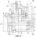
- FIG. 2 is a cross-sectional view of the drive unit 100
- FIG. 3 is a side view of the drive unit 100.
- the drive unit 100 includes the rotary electric machine 10, a speed reducer 20 serving as a speed reduction mechanism, a first shaft 30, the second shaft 40 serving as a shaft, a housing 50, a flywheel 60, and a pulley 70.
- the rotary electric machine 10 functions as an electric motor and/or a generator.
- the rotary electric machine 10 is disposed on a first axis C1.
- the rotary electric machine 10 includes a stator 11 and a rotor 12.
- the stator 11 is non-rotatably supported by a motor support portion 51c of the housing 50, which will be described later.
- the rotor 12 is provided on an inner periphery of the stator 11 and rotates with respect to the stator 11.
- a small-diameter gear 21 is attached to the rotor 12 via the first shaft 30. The rotor 12 rotates together with the first shaft 30 and the small-diameter gear 21.
- the speed reducer 20 includes the small-diameter gear 21 as a first gear and a large-diameter gear 22 as a second gear.
- the small-diameter gear 21 is connected downstream of the rotary electric machine 10.
- the small-diameter gear 21 is disposed on the first axis C1.
- the expression "disposed on the first axis C1" means being disposed coaxially with other components disposed on the first axis C1.
- the large-diameter gear 22 meshes with the small-diameter gear 21.
- the large-diameter gear 22 is disposed on a second axis C2 parallel to the first axis C1.
- the expression "disposed on the second axis C2" means being disposed coaxially with other components disposed on the second axis C2.
- the large-diameter gear 22 is formed to have a diameter larger than that of the small-diameter gear 21. Therefore, the small-diameter gear 21 and the large-diameter gear 22 constitute the speed reducer 20 that reduces a speed of an output of the rotary electric machine 10 and transmits the output to a downstream side.
- a dimension (W1) in a radial direction of the rotary electric machine MG is equal to an outer diameter of the unit and is the same dimension in any direction. Therefore, a dimension in a width direction of the unit may increase.
- a dimension in the first direction (here, a height direction) in which the small-diameter gear 21 and the large-diameter gear 22 are arranged side by side is larger than that of the rotary electric machine MG, but a dimension (W2) in the second direction (here, the width direction) as a predetermined direction intersecting (here, orthogonal to) the first direction can be made smaller than that of the rotary electric machine MG (W2 ⁇ W1). Accordingly, it is possible to provide an advantageous layout when restriction in the first direction is loose and restriction in the second direction is severe. Accordingly, the dimension in the predetermined direction of the drive unit 100 can be reduced.
- the large-diameter gear 22 is disposed to be sandwiched between the first output end 40a and the second output end 40b of the second shaft 40, and is located on the first output end 40a side.
- a change in behavior transmitted to an input element (here, the transmission 2) of the first output end 40a is directly linked to the change in behavior of the driving wheels 5.
- a change in behavior transmitted to the auxiliary machine 3 is not directly linked to the change in behavior of the vehicle 1 felt by the driver during driving.
- the large-diameter gear 22 at a position closer to the first output end 40a than the second output end 40b, a distance between the large-diameter gear 22 and the first output end 40a can be reduced, and therefore an influence of torsion or deflection of the second shaft 40 can be suppressed and the change in behavior of the vehicle 1 can be reduced.
- the first shaft 30 supports the small-diameter gear 21 and the rotor 12 of the rotary electric machine 10.
- the first shaft 30 is an output shaft of the rotary electric machine 10.
- the first shaft 30 is provided with a resolver 33 as a rotation speed detector for detecting a rotation speed.
- the first shaft 30 rotates about the first axis C1.
- the first shaft 30 is rotatably supported by the housing 50 via a bearing 31 and a bearing 32.
- the second shaft 40 is connected downstream of the large-diameter gear 22.
- the second shaft 40 is disposed on the second axis C2.
- the second shaft 40 rotates about the second axis C2.
- the second shaft 40 is rotatably supported by the housing 50 via a bearing 41 and a bearing 42.
- the second shaft 40 is provided at the same position as a crankshaft (not shown) of the internal combustion engine 9 (see FIG. 6 ) removed from the vehicle 1.
- the second shaft 40 includes the first output end 40a and the second output end 40b.
- the first output end 40a and the second output end 40b are arranged on the second axis C2.
- the first output end 40a and the second output end 40b are provided at the same positions as a first output end and a second output end of the crankshaft, respectively.
- the housing 50 is a housing member that houses the rotary electric machine 10, the speed reducer 20, the first shaft 30, the second shaft 40, and an inverter (not shown).
- the housing 50 is implemented by one or more cases. Specifically, the housing 50 is implemented by a first case 51, a second case 52, and a third case 53.
- the housing 50 forms a 3-in-1 (three-in-one) drive unit 100.
- the 3-in-1 means that a part of a motor case housing the rotary electric machine 10, a part of a speed reducer case housing the speed reducer 20, and a part of an inverter case housing the inverter are integrally formed.
- the first case 51 is formed in a tubular shape with both ends open.
- the first case 51 includes a support wall 51a, a shaft support portion 51b, and the motor support portion 51c.
- the support wall 51a is provided perpendicular to an axial direction of the first case 51.
- the axial direction means an axial direction of a rotation axis of components constituting the drive unit 100.
- the components are, for example, the rotary electric machine 10 and the speed reducer 20.
- the support wall 51a rotatably supports the first shaft 30 via the bearing 32.
- the resolver 33 and a cover 34 that houses the resolver 33 are attached to the support wall 51a.
- the second case 52 is provided side by side with the first case 51 in the axial direction.
- the second case 52 closes one opening of the first case 51.
- the second case 52 rotatably supports the first shaft 30 via the bearing 31 and rotatably supports the second shaft 40 via the bearing 41.
- the third case 53 is provided side by side with the first case 51 and the second case 52 in the axial direction.
- the third case 53 closes the other opening of the first case 51.
- the flywheel 60 is disposed on the second axis C2.
- the flywheel 60 transmits the output torque of the drive unit 100 to the transmission 2.
- the flywheel 60 is provided at the same position as a flywheel (not shown) of the internal combustion engine 9 (see FIG. 6 ) removed from the vehicle 1.
- the pulley 70 is disposed on the second axis C2.
- the belt 4 is wound around the pulley 70.
- the pulley 70 transmits the driving force of the drive unit 100 to the auxiliary machine 3 via the belt 4.
- the pulley 70 is provided at the same position as a pulley (not shown) of the internal combustion engine 9 (see FIG. 6 ) removed from the vehicle 1.
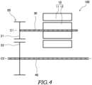
- FIG. 4 is a skeleton diagram of the unit.
- FIG. 5 is a skeleton diagram of a drive unit 200 as a unit according to the comparative example.
- the speed reducer 120 is a planetary gear mechanism including a sun gear 121, a planetary gear 122, a carrier 123, and a ring gear 124.
- the ring gear 124 is non-rotatably supported by a housing 150.
- the speed reducer 120 reduces the output torque of the rotary electric machine 10 input from the sun gear 121 via the first shaft 30, and outputs the reduced torque to a downstream side from the carrier 123 via the second shaft 40. Accordingly, the drive unit 200 can output the driving force from both ends of the second shaft 40.
- the second shaft 40 passes through an inner periphery of the first shaft 30. Therefore, it is necessary to form the first shaft 30 in a tubular shape having a through hole of a size through which the second shaft 40 can be inserted, and the outer diameter of the rotary electric machine 10 may increase in all directions in the radial direction.
- the dimension in the first direction (here, the height direction) in which the small-diameter gear 21 and the large-diameter gear 22 are arranged side by side is larger than that of the drive unit 200, but the dimension in the second direction (here, the width direction) as a predetermined direction intersecting (here, orthogonal to) the first direction can be made smaller than that of the drive unit 200. Accordingly, it is possible to provide an advantageous layout when restriction in the first direction is loose and restriction in the second direction is severe. Accordingly, the dimension in the predetermined direction of the drive unit 100 can be reduced.
- FIG. 6 is a configuration diagram illustrating a first step of the method for manufacturing the vehicle 1.
- FIG. 7 is a configuration diagram illustrating a second step of the method for manufacturing the vehicle 1.
- the method for manufacturing the vehicle 1 is for manufacturing the vehicle 1 that includes the transmission 2, the belt 4, the driving wheels 5 connected downstream of the transmission 2, and the auxiliary machine 3 connected downstream of the belt 4, in which an input portion (flywheel 60) of the transmission 2 and an input portion (pulley 70) of the belt 4 are coaxially arranged.
- the method for manufacturing the vehicle 1 includes the first step and the second step.
- the drive unit 100 is prepared.
- the drive unit 100 includes the rotary electric machine 10, the small-diameter gear 21 connected downstream of the rotary electric machine 10, the large-diameter gear 22 that meshes with the small-diameter gear 21, and the second shaft 40 connected downstream of the large-diameter gear 22.
- the second shaft 40 includes the first output end 40a and the second output end 40b.
- the rotary electric machine 10 and the small-diameter gear 21 are arranged on the first axis C1.
- the large-diameter gear 22, the second shaft 40, the first output end 40a and the second output end 40b are arranged on the second axis C2.
- the large-diameter gear 22 is disposed and sandwiched between the first output end 40a and the second output end 40b.
- two power transmission mechanisms (the transmission 2 and the belt 4) can be implemented in a coaxial state.
- the method for manufacturing the vehicle 1 includes a step of removing the internal combustion engine 9 connected to the input portion of the transmission 2 and the input portion of the belt 4 at least before the second step.
- the drive unit 100 may be prepared after the internal combustion engine 9 is removed, or the drive unit 100 may be prepared in advance before the internal combustion engine 9 is removed.
- the drive unit 100 is mounted on the vehicle 1.
- the first output end 40a is connected to the input portion of the transmission 2
- the second output end 40b is connected to the input portion of the belt 4.
- the input portion of the transmission 2 and the input portion of the belt 4 are often provided coaxially, and application of the drive unit 100 having such a configuration to a conversion EV in which the vehicle 1 with the internal combustion engine 9 is modified into an electric vehicle is an advantageous modification method.
- the modification is not only an action of reproduction, and the modification method is also a method for producing an object (manufacturing method).
- the input portion of the transmission 2 and the input portion of the belt 4 are often provided coaxially, and application of the drive unit 100 having such a configuration to a conversion EV in which the vehicle 1 with the internal combustion engine 9 is modified into an electric vehicle is an advantageous modification method.
- the modification is not only an action of reproduction, and the modification method is also a method for producing an object (manufacturing method).
- the drive unit 100 may be prepared after the internal combustion engine 9 is removed, or the drive unit 100 may be prepared in advance before the internal combustion engine 9 is removed.
- a length in the axial direction of the rotary electric machine 10 may be increased, a length in the axial direction of the first case 51 in the housing 50 may be increased, and a length of the second shaft 40 may be increased.
- the dimension in the first direction in which the small-diameter gear 21 and the large-diameter gear 22 are arranged side by side is increased, but the dimension in the second direction (predetermined direction) intersecting the first direction can be reduced.
Landscapes
- Engineering & Computer Science (AREA)
- Mechanical Engineering (AREA)
- General Engineering & Computer Science (AREA)
- Transportation (AREA)
- Chemical & Material Sciences (AREA)
- Combustion & Propulsion (AREA)
- Power Engineering (AREA)
- Manufacturing & Machinery (AREA)
- Gear Transmission (AREA)
Abstract
Description
- The present invention relates to a unit, a vehicle, and a vehicle manufacturing method.
-
Patent Document 1 discloses a unit including an electric motor, an automatic transmission, and a linkage unit that transmits power of the electric motor to the automatic transmission. - Patent Document 1:
JP2013-005637A - However, in the unit of
Patent Document 1, dimensions in a radial direction of the electric motor and the power transmission device are equal to an outer diameter of the unit and are the same in any direction. - An object of the present invention is to reduce a dimension of a unit in a predetermined direction.
- According to one aspect of the present invention, a unit includes: a rotary electric machine; a first gear connected downstream of the rotary electric machine; a second gear configured to mesh with the first gear; and a shaft connected downstream of the second gear, in which the shaft includes a first output end and a second output end, the rotary electric machine and the first gear are arranged on a first axis, the second gear, the shaft, the first output end, and the second output end are arranged on a second axis, and the second gear is disposed to be sandwiched between the first output end and the second output end.
- According to one aspect of the present invention, a dimension in a first direction in which the first gear and the second gear are arranged side by side is increased, but a dimension in a second direction (predetermined direction) intersecting the first direction can be reduced. Accordingly, it is possible to provide an advantageous layout when restriction in the first direction is loose and restriction in the second direction is severe. Accordingly, a dimension of the unit in the predetermined direction can be reduced.
-
- [
FIG. 1] FIG. 1 is a configuration diagram of a vehicle including a unit according to an embodiment of the present invention. - [
FIG. 2] FIG. 2 is a cross-sectional view of the unit. - [
FIG. 3] FIG. 3 is a side view of the unit. - [
FIG. 4] FIG. 4 is a skeleton diagram of the unit. - [
FIG. 5] FIG. 5 is a skeleton diagram of a unit according to a comparative example. - [
FIG. 6] FIG. 6 is a configuration diagram illustrating a first step of a vehicle manufacturing method. - [
FIG. 7] FIG. 7 is a configuration diagram illustrating a second step of the vehicle manufacturing method. - Hereinafter, a
drive unit 100 as a unit according to an embodiment of the present invention and avehicle 1 including thedrive unit 100 will be described with reference to the drawings. - First, the
vehicle 1 will be described with reference toFIG. 1. FIG. 1 is a configuration diagram of thevehicle 1 including thedrive unit 100. - The
vehicle 1 is a so-called conversion electric vehicle (EV) in which aninternal combustion engine 9 is removed from the vehicle driven by the internal combustion engine 9 (seeFIG. 6 ), thedrive unit 100 is mounted instead, and thevehicle 1 is driven by thedrive unit 100. Thevehicle 1 includes thedrive unit 100, atransmission 2 serving as a first power transmission mechanism, anauxiliary machine 3, abelt 4 serving as a second power transmission mechanism, anddriving wheels 5. - The
drive unit 100 is an electric drive unit including a rotary electric machine 10 (seeFIG. 2 ) described later. A specific configuration of thedrive unit 100 will be described later in detail with reference toFIG. 2 . - Note that the unit is used to drive the
driving wheels 5 of thevehicle 1, but is not limited thereto, and may be used to drive an electrical product, for example. The unit is also called a motor unit (a unit including at least a motor), a power transmission device (a device including at least a power transmission mechanism (for example, a gear mechanism and/or a differential gear mechanism)), or the like. Note that a device (unit) including a motor and a power transmission mechanism belongs to concepts of both a motor unit and a power transmission device. - The
transmission 2 changes a speed of a driving force from thedrive unit 100 and transmits the driving force to thedriving wheels 5. Thetransmission 2 may be an automatic transmission or a manual transmission. - The
auxiliary machine 3 is driven by thedrive unit 100. Theauxiliary machine 3 is, for example, an alternator that is rotationally driven by the rotaryelectric machine 10 to generate electric power. Theauxiliary machine 3 is connected downstream of asecond output end 40b (seeFIG. 2 ) of asecond shaft 40 described later. - The
belt 4 transmits the driving force of thedrive unit 100 to theauxiliary machine 3. - The
driving wheels 5 are connected downstream of afirst output end 40a (seeFIG. 2 ) of thesecond shaft 40 described later. Here, thedriving wheels 5 are rear wheels of thevehicle 1, but may be front wheels of thevehicle 1. - Next, a configuration of the
drive unit 100 will be described with reference toFIGS. 2 and3 .FIG. 2 is a cross-sectional view of thedrive unit 100, andFIG. 3 is a side view of thedrive unit 100. - As shown in
FIG. 2 , thedrive unit 100 includes the rotaryelectric machine 10, aspeed reducer 20 serving as a speed reduction mechanism, afirst shaft 30, thesecond shaft 40 serving as a shaft, ahousing 50, aflywheel 60, and apulley 70. - The rotary
electric machine 10 functions as an electric motor and/or a generator. The rotaryelectric machine 10 is disposed on a first axis C1. The rotaryelectric machine 10 includes astator 11 and arotor 12. Thestator 11 is non-rotatably supported by amotor support portion 51c of thehousing 50, which will be described later. Therotor 12 is provided on an inner periphery of thestator 11 and rotates with respect to thestator 11. A small-diameter gear 21 is attached to therotor 12 via thefirst shaft 30. Therotor 12 rotates together with thefirst shaft 30 and the small-diameter gear 21. - The
speed reducer 20 includes the small-diameter gear 21 as a first gear and a large-diameter gear 22 as a second gear. - The small-
diameter gear 21 is connected downstream of the rotaryelectric machine 10. The small-diameter gear 21 is disposed on the first axis C1. The expression "disposed on the first axis C1" means being disposed coaxially with other components disposed on the first axis C1. - The large-
diameter gear 22 meshes with the small-diameter gear 21. The large-diameter gear 22 is disposed on a second axis C2 parallel to the first axis C1. The expression "disposed on the second axis C2" means being disposed coaxially with other components disposed on the second axis C2. The large-diameter gear 22 is formed to have a diameter larger than that of the small-diameter gear 21. Therefore, the small-diameter gear 21 and the large-diameter gear 22 constitute thespeed reducer 20 that reduces a speed of an output of the rotaryelectric machine 10 and transmits the output to a downstream side. - Here, as shown in
FIG. 3 , if the same output as that of thedrive unit 100 is generated only by the rotary electric machine MG, a dimension (W1) in a radial direction of the rotary electric machine MG is equal to an outer diameter of the unit and is the same dimension in any direction. Therefore, a dimension in a width direction of the unit may increase. - In contrast, in the
drive unit 100, a dimension in the first direction (here, a height direction) in which the small-diameter gear 21 and the large-diameter gear 22 are arranged side by side is larger than that of the rotary electric machine MG, but a dimension (W2) in the second direction (here, the width direction) as a predetermined direction intersecting (here, orthogonal to) the first direction can be made smaller than that of the rotary electric machine MG (W2 < W1). Accordingly, it is possible to provide an advantageous layout when restriction in the first direction is loose and restriction in the second direction is severe. Accordingly, the dimension in the predetermined direction of thedrive unit 100 can be reduced. - The larger a maximum output torque of the rotary
electric machine 10, the larger a size thereof becomes, but by providing thespeed reducer 20 downstream of the rotaryelectric machine 10, a torque of the rotaryelectric machine 10 is increased by thespeed reducer 20. Accordingly, the maximum output torque of the rotaryelectric machine 10 can be set to be small, and therefore, an option for reducing the size of the rotaryelectric machine 10 can be provided. - As shown in
FIG. 2 , the large-diameter gear 22 is disposed to be sandwiched between thefirst output end 40a and thesecond output end 40b of thesecond shaft 40, and is located on thefirst output end 40a side. - Since a driver feels a change in behavior of the
driving wheels 5 as a change in behavior of thevehicle 1 during driving, an influence of the behavior of thedriving wheels 5 is important. A change in behavior transmitted to an input element (here, the transmission 2) of thefirst output end 40a is directly linked to the change in behavior of thedriving wheels 5. On the other hand, a change in behavior transmitted to theauxiliary machine 3 is not directly linked to the change in behavior of thevehicle 1 felt by the driver during driving. Therefore, by providing the large-diameter gear 22 at a position closer to thefirst output end 40a than thesecond output end 40b, a distance between the large-diameter gear 22 and thefirst output end 40a can be reduced, and therefore an influence of torsion or deflection of thesecond shaft 40 can be suppressed and the change in behavior of thevehicle 1 can be reduced. - The
first shaft 30 supports the small-diameter gear 21 and therotor 12 of the rotaryelectric machine 10. Thefirst shaft 30 is an output shaft of the rotaryelectric machine 10. Thefirst shaft 30 is provided with aresolver 33 as a rotation speed detector for detecting a rotation speed. Thefirst shaft 30 rotates about the first axis C1. Thefirst shaft 30 is rotatably supported by thehousing 50 via abearing 31 and abearing 32. - The
second shaft 40 is connected downstream of the large-diameter gear 22. Thesecond shaft 40 is disposed on the second axis C2. Thesecond shaft 40 rotates about the second axis C2. Thesecond shaft 40 is rotatably supported by thehousing 50 via abearing 41 and abearing 42. Thesecond shaft 40 is provided at the same position as a crankshaft (not shown) of the internal combustion engine 9 (seeFIG. 6 ) removed from thevehicle 1. - The
second shaft 40 includes thefirst output end 40a and thesecond output end 40b. Thefirst output end 40a and thesecond output end 40b are arranged on the second axis C2. Thefirst output end 40a and thesecond output end 40b are provided at the same positions as a first output end and a second output end of the crankshaft, respectively. - The
housing 50 is a housing member that houses the rotaryelectric machine 10, thespeed reducer 20, thefirst shaft 30, thesecond shaft 40, and an inverter (not shown). Thehousing 50 is implemented by one or more cases. Specifically, thehousing 50 is implemented by afirst case 51, asecond case 52, and athird case 53. - The
housing 50 forms a 3-in-1 (three-in-one)drive unit 100. The 3-in-1 means that a part of a motor case housing the rotaryelectric machine 10, a part of a speed reducer case housing thespeed reducer 20, and a part of an inverter case housing the inverter are integrally formed. - The
first case 51 is formed in a tubular shape with both ends open. Thefirst case 51 includes asupport wall 51a, ashaft support portion 51b, and themotor support portion 51c. - The
support wall 51a is provided perpendicular to an axial direction of thefirst case 51. The axial direction means an axial direction of a rotation axis of components constituting thedrive unit 100. The components are, for example, the rotaryelectric machine 10 and thespeed reducer 20. Thesupport wall 51a rotatably supports thefirst shaft 30 via thebearing 32. Theresolver 33 and acover 34 that houses theresolver 33 are attached to thesupport wall 51a. - The
second case 52 is provided side by side with thefirst case 51 in the axial direction. Thesecond case 52 closes one opening of thefirst case 51. Thesecond case 52 rotatably supports thefirst shaft 30 via thebearing 31 and rotatably supports thesecond shaft 40 via thebearing 41. - The
third case 53 is provided side by side with thefirst case 51 and thesecond case 52 in the axial direction. Thethird case 53 closes the other opening of thefirst case 51. - The
flywheel 60 is disposed on the second axis C2. Theflywheel 60 transmits the output torque of thedrive unit 100 to thetransmission 2. Theflywheel 60 is provided at the same position as a flywheel (not shown) of the internal combustion engine 9 (seeFIG. 6 ) removed from thevehicle 1. - The
pulley 70 is disposed on the second axis C2. Thebelt 4 is wound around thepulley 70. Thepulley 70 transmits the driving force of thedrive unit 100 to theauxiliary machine 3 via thebelt 4. Thepulley 70 is provided at the same position as a pulley (not shown) of the internal combustion engine 9 (seeFIG. 6 ) removed from thevehicle 1. - Note that when the
internal combustion engine 9 is removed, thepulley 70 is left in thevehicle 1 without being removed together with theinternal combustion engine 9, and when thepulley 70 is used in attaching thedrive unit 100, thepulley 70 constitutes the second power transmission mechanism. - Next, advantages of the
drive unit 100 in comparison with a comparative example will be described with reference toFIGS. 4 and5 .FIG. 4 is a skeleton diagram of the unit.FIG. 5 is a skeleton diagram of adrive unit 200 as a unit according to the comparative example. - As shown in
FIG. 5 , thedrive unit 200 according to the comparative example includes the rotaryelectric machine 10, aspeed reducer 120 serving as a speed reduction mechanism, thefirst shaft 30, and thesecond shaft 40. - The
speed reducer 120 is a planetary gear mechanism including asun gear 121, aplanetary gear 122, acarrier 123, and aring gear 124. In thespeed reducer 120, thering gear 124 is non-rotatably supported by ahousing 150. Thespeed reducer 120 reduces the output torque of the rotaryelectric machine 10 input from thesun gear 121 via thefirst shaft 30, and outputs the reduced torque to a downstream side from thecarrier 123 via thesecond shaft 40. Accordingly, thedrive unit 200 can output the driving force from both ends of thesecond shaft 40. - However, in the
drive unit 200, thesecond shaft 40 passes through an inner periphery of thefirst shaft 30. Therefore, it is necessary to form thefirst shaft 30 in a tubular shape having a through hole of a size through which thesecond shaft 40 can be inserted, and the outer diameter of the rotaryelectric machine 10 may increase in all directions in the radial direction. - In contrast, as illustrated in
FIG. 4 , in thedrive unit 100, the dimension in the first direction (here, the height direction) in which the small-diameter gear 21 and the large-diameter gear 22 are arranged side by side is larger than that of thedrive unit 200, but the dimension in the second direction (here, the width direction) as a predetermined direction intersecting (here, orthogonal to) the first direction can be made smaller than that of thedrive unit 200. Accordingly, it is possible to provide an advantageous layout when restriction in the first direction is loose and restriction in the second direction is severe. Accordingly, the dimension in the predetermined direction of thedrive unit 100 can be reduced. - Hereinafter, a method for manufacturing the
vehicle 1 will be described with reference toFIGS. 6 and 7. FIG. 6 is a configuration diagram illustrating a first step of the method for manufacturing thevehicle 1.FIG. 7 is a configuration diagram illustrating a second step of the method for manufacturing thevehicle 1. - The method for manufacturing the
vehicle 1 is for manufacturing thevehicle 1 that includes thetransmission 2, thebelt 4, thedriving wheels 5 connected downstream of thetransmission 2, and theauxiliary machine 3 connected downstream of thebelt 4, in which an input portion (flywheel 60) of thetransmission 2 and an input portion (pulley 70) of thebelt 4 are coaxially arranged. The method for manufacturing thevehicle 1 includes the first step and the second step. - First, as shown in
FIG. 6 , in the first step, thedrive unit 100 is prepared. As described above, thedrive unit 100 includes the rotaryelectric machine 10, the small-diameter gear 21 connected downstream of the rotaryelectric machine 10, the large-diameter gear 22 that meshes with the small-diameter gear 21, and thesecond shaft 40 connected downstream of the large-diameter gear 22. Thesecond shaft 40 includes thefirst output end 40a and thesecond output end 40b. The rotaryelectric machine 10 and the small-diameter gear 21 are arranged on the first axis C1. The large-diameter gear 22, thesecond shaft 40, thefirst output end 40a and thesecond output end 40b are arranged on the second axis C2. The large-diameter gear 22 is disposed and sandwiched between thefirst output end 40a and thesecond output end 40b. - In this way, by preparing the
drive unit 100, two power transmission mechanisms (thetransmission 2 and the belt 4) can be implemented in a coaxial state. - The method for manufacturing the
vehicle 1 includes a step of removing theinternal combustion engine 9 connected to the input portion of thetransmission 2 and the input portion of thebelt 4 at least before the second step. - That is, the
drive unit 100 may be prepared after theinternal combustion engine 9 is removed, or thedrive unit 100 may be prepared in advance before theinternal combustion engine 9 is removed. - Subsequently, as shown in
FIG. 7 , in the second step, thedrive unit 100 is mounted on thevehicle 1. In this case, thefirst output end 40a is connected to the input portion of thetransmission 2, and thesecond output end 40b is connected to the input portion of thebelt 4. - In the
internal combustion engine 9, the input portion of thetransmission 2 and the input portion of thebelt 4 are often provided coaxially, and application of thedrive unit 100 having such a configuration to a conversion EV in which thevehicle 1 with theinternal combustion engine 9 is modified into an electric vehicle is an advantageous modification method. Note that the modification is not only an action of reproduction, and the modification method is also a method for producing an object (manufacturing method). - Since the
internal combustion engine 9 exists in a vertically long space as viewed in the axial direction, when the conversion EV is manufactured, restriction in the vertical direction is loose and restriction in the horizontal direction is severe. Therefore, in such a case, it is very preferable to apply thedrive unit 100 having the configuration. - The configurations and effects of the present embodiment described above will be collectively described.
- (1) The
drive unit 100 includes the rotaryelectric machine 10, the small-diameter gear 21 connected downstream of the rotaryelectric machine 10, the large-diameter gear 22 meshing with the small-diameter gear 21, and thesecond shaft 40 connected downstream of the large-diameter gear 22. Thesecond shaft 40 includes thefirst output end 40a and thesecond output end 40b. The rotaryelectric machine 10 and the small-diameter gear 21 are arranged on the first axis C1. The large-diameter gear 22, thesecond shaft 40, thefirst output end 40a and thesecond output end 40b are arranged on the second axis C2. The large-diameter gear 22 is disposed to be sandwiched between thefirst output end 40a and thesecond output end 40b.
According to this configuration, the dimension in the first direction in which the small-diameter gear 21 and the large-diameter gear 22 are arranged side by side is increased, but the dimension in the second direction (predetermined direction) intersecting the first direction can be reduced. Accordingly, it is possible to provide an advantageous layout when restriction in the first direction is loose and restriction in the second direction is severe. Accordingly, the dimension in the predetermined direction of thedrive unit 100 can be reduced. - (2) The small-
diameter gear 21 and the large-diameter gear 22 constitute thespeed reducer 20.
According to this configuration, the larger the maximum output torque of the rotaryelectric machine 10, the larger the size thereof becomes, but by providing thespeed reducer 20 downstream of the rotaryelectric machine 10, the torque of the rotaryelectric machine 10 is increased by thespeed reducer 20. Accordingly, the maximum output torque of the rotaryelectric machine 10 can be set to be small, and therefore, an option for reducing the size of the rotaryelectric machine 10 can be provided. - (3) The
vehicle 1 includes thedriving wheels 5 connected downstream of thefirst output end 40a and theauxiliary machine 3 connected downstream of thesecond output end 40b, and the large-diameter gear 22 is located on thefirst output end 40a side.
Since the driver feels the change in behavior of thedriving wheels 5 as the change in behavior of thevehicle 1 during driving, the influence of the behavior of thedriving wheels 5 is important. The change in behavior transmitted to the input element (here, the transmission 2) of thefirst output end 40a is directly linked to the change in behavior of thedriving wheels 5. On the other hand, the change in behavior transmitted to theauxiliary machine 3 is not directly linked to the change in behavior of thevehicle 1 felt by the driver during driving. Therefore, by providing the large-diameter gear 22 at a position closer to thefirst output end 40a than thesecond output end 40b, the distance between the large-diameter gear 22 and thefirst output end 40a can be reduced, and therefore the influence of torsion or deflection of thesecond shaft 40 can be suppressed and the change in behavior of thevehicle 1 can be reduced. - (4) The method for manufacturing the vehicle 1 including the transmission 2, the belt 4, the driving wheels 5 connected downstream of the transmission 2, and the auxiliary machine 3 connected downstream of the belt 4, in which the input portion (flywheel 60) of the transmission 2 and the input portion (pulley 70) of the belt 4 are coaxially arranged includes: the first step of preparing the drive unit 100 including the rotary electric machine 10, the small-diameter gear 21 connected downstream of the rotary electric machine 10, the large-diameter gear 22 meshing with the small-diameter gear 21, and the second shaft 40 connected downstream of the large-diameter gear 22, in which the second shaft 40 includes the first output end 40a and the second output end 40b, the rotary electric machine 10 and the small-diameter gear 21 are arranged on the first axis C1, the large-diameter gear 22, the second shaft 40, the first output end 40a and the second output end 40b are arranged on the second axis C2, and the large-diameter gear 22 is disposed to be sandwiched between the first output end 40a and the second output end 40b, and the second step of mounting the drive unit 100 such that the first output end 40a is connected to the input portion of the transmission 2 and the second output end 40b is connected to the input portion of the belt 4.
According to this configuration, the dimension in the first direction in which the small-diameter gear 21 and the large-diameter gear 22 are arranged side by side is increased, but the dimension in the second direction (predetermined direction) intersecting the first direction can be reduced. Accordingly, it is possible to provide an advantageous layout when restriction in the first direction is loose and restriction in the second direction is severe. Accordingly, the dimension in the predetermined direction of thedrive unit 100 can be reduced.
By preparing thedrive unit 100 having such a configuration, the two power transmission mechanisms (thetransmission 2 and the belt 4) can be implemented in a coaxial state. - (5) The method for manufacturing the
vehicle 1 includes the step of removing theinternal combustion engine 9 connected to the input portion of thetransmission 2 and the input portion of thebelt 4 at least before the second step. - According to this configuration, in the
internal combustion engine 9, the input portion of thetransmission 2 and the input portion of thebelt 4 are often provided coaxially, and application of thedrive unit 100 having such a configuration to a conversion EV in which thevehicle 1 with theinternal combustion engine 9 is modified into an electric vehicle is an advantageous modification method. Note that the modification is not only an action of reproduction, and the modification method is also a method for producing an object (manufacturing method). - Since the
internal combustion engine 9 exists in a vertically long space as viewed in the axial direction, when the conversion EV is manufactured, restriction in the vertical direction is loose and restriction in the horizontal direction is severe. Therefore, in such a case, it is very preferable to apply thedrive unit 100 having the configuration. - Note that the
drive unit 100 may be prepared after theinternal combustion engine 9 is removed, or thedrive unit 100 may be prepared in advance before theinternal combustion engine 9 is removed. - Although the embodiment of the present invention has been described above, the above embodiment is merely an application example of the present invention and is not intended to limit the technical scope of the present invention to the specific configuration of the above embodiment.
- For example, when it is desired to increase the output of the
drive unit 100, a length in the axial direction of the rotaryelectric machine 10 may be increased, a length in the axial direction of thefirst case 51 in thehousing 50 may be increased, and a length of thesecond shaft 40 may be increased. Under this case, similarly, the dimension in the first direction in which the small-diameter gear 21 and the large-diameter gear 22 are arranged side by side is increased, but the dimension in the second direction (predetermined direction) intersecting the first direction can be reduced. -
- 100
- drive unit (unit)
- 1
- vehicle
- 2
- transmission (first power transmission mechanism)
- 3
- auxiliary machine
- 4
- belt (second power transmission mechanism)
- 5
- driving wheel
- 9
- internal combustion engine
- 10
- rotary electric machine
- 20
- speed reducer (speed reduction mechanism)
- 21
- small-diameter gear
- 22
- large-diameter gear
- 40
- second shaft (shaft)
- 40a
- first output end
- 40b
- second output end
- C1
- first axis
- C2
- second axis
Claims (5)
- A unit, comprising:a rotary electric machine;a first gear connected downstream of the rotary electric machine;a second gear configured to mesh with the first gear; anda shaft connected downstream of the second gear, whereinthe shaft includes a first output end and a second output end,the rotary electric machine and the first gear are arranged on a first axis,the second gear, the shaft, the first output end, and the second output end are arranged on a second axis, andthe second gear is disposed to be sandwiched between the first output end and the second output end.
- The unit according to claim 1, wherein
the first gear and the second gear constitute a speed reduction mechanism. - A vehicle equipped with the unit according to claim 1 or 2, comprising:a driving wheel connected downstream of the first output end; andan auxiliary machine connected downstream of the second output end, whereinthe second gear is located on a first output end side.
- A vehicle manufacturing method for manufacturing a vehicle which includes a first power transmission mechanism, a second power transmission mechanism, a driving wheel connected downstream of the first power transmission mechanism, and an auxiliary machine connected downstream of the second power transmission mechanism, and in which an input portion of the first power transmission mechanism and an input portion of the second power transmission mechanism are coaxially arranged, the vehicle manufacturing method comprising:a first step of preparing a unit which includes a rotary electric machine, a first gear connected downstream of the rotary electric machine, a second gear configured to mesh with the first gear, and a shaft connected downstream of the second gear, and in which the shaft includes a first output end and a second output end, the rotary electric machine and the first gear are arranged on a first axis, the second gear, the shaft, the first output end, and the second output end are arranged on a second axis, and the second gear is disposed to be sandwiched between the first output end and the second output end; anda second step of mounting the unit such that the first output end is connected to the input portion of the first power transmission mechanism and the second output end is connected to the input portion of the second power transmission mechanism.
- The vehicle manufacturing method according to claim 4, further comprising:
a step of removing an internal combustion engine connected to the input portion of the first power transmission mechanism and the input portion of the second power transmission mechanism at least before the second step.
Applications Claiming Priority (2)
| Application Number | Priority Date | Filing Date | Title |
|---|---|---|---|
| JP2022095651 | 2022-06-14 | ||
| PCT/JP2023/017789 WO2023243272A1 (en) | 2022-06-14 | 2023-05-11 | Unit, vehicle, and method for manufacturing vehicle |
Publications (2)
| Publication Number | Publication Date |
|---|---|
| EP4542081A1 true EP4542081A1 (en) | 2025-04-23 |
| EP4542081A4 EP4542081A4 (en) | 2025-09-24 |
Family
ID=89191019
Family Applications (1)
| Application Number | Title | Priority Date | Filing Date |
|---|---|---|---|
| EP23823575.8A Pending EP4542081A4 (en) | 2022-06-14 | 2023-05-11 | UNIT, VEHICLE AND METHOD FOR MANUFACTURING A VEHICLE |
Country Status (5)
| Country | Link |
|---|---|
| US (1) | US20250368020A1 (en) |
| EP (1) | EP4542081A4 (en) |
| JP (1) | JP7765632B2 (en) |
| CN (1) | CN119365704A (en) |
| WO (1) | WO2023243272A1 (en) |
Families Citing this family (1)
| Publication number | Priority date | Publication date | Assignee | Title |
|---|---|---|---|---|
| EP4538559A4 (en) * | 2022-06-13 | 2025-09-24 | Jatco Ltd | UNIT |
Family Cites Families (9)
| Publication number | Priority date | Publication date | Assignee | Title |
|---|---|---|---|---|
| US4548042A (en) * | 1982-07-19 | 1985-10-22 | Brothers Luther C | Propulsion system |
| DE102010009832A1 (en) * | 2010-03-02 | 2011-09-08 | Ivd Prof. Hohenberg Gmbh | Motor vehicle with combined drive |
| JP5669019B2 (en) | 2011-06-20 | 2015-02-12 | 愛媛県 | Convert EV power transmission device |
| DE202017000454U1 (en) * | 2017-01-27 | 2018-04-30 | Jochen Bühler | Conversion kit or conversion kit for vehicles with combustion engine on electric drive |
| JP2020099119A (en) * | 2018-12-17 | 2020-06-25 | トヨタ自動車株式会社 | Vehicle drive system |
| JP7336189B2 (en) * | 2018-12-25 | 2023-08-31 | ダイハツ工業株式会社 | vehicle |
| JP2021010269A (en) * | 2019-07-02 | 2021-01-28 | 本田技研工業株式会社 | Drive unit and vehicle |
| JP7376382B2 (en) * | 2020-02-21 | 2023-11-08 | 日野自動車株式会社 | drive device |
| WO2022067632A1 (en) * | 2020-09-30 | 2022-04-07 | 罗伯特·博世有限公司 | Electric vehicle and electric power system comprising same |
-
2023
- 2023-05-11 EP EP23823575.8A patent/EP4542081A4/en active Pending
- 2023-05-11 CN CN202380046522.2A patent/CN119365704A/en active Pending
- 2023-05-11 JP JP2024528380A patent/JP7765632B2/en active Active
- 2023-05-11 US US18/874,514 patent/US20250368020A1/en active Pending
- 2023-05-11 WO PCT/JP2023/017789 patent/WO2023243272A1/en not_active Ceased
Also Published As
| Publication number | Publication date |
|---|---|
| EP4542081A4 (en) | 2025-09-24 |
| WO2023243272A1 (en) | 2023-12-21 |
| US20250368020A1 (en) | 2025-12-04 |
| CN119365704A (en) | 2025-01-24 |
| JP7765632B2 (en) | 2025-11-06 |
| JPWO2023243272A1 (en) | 2023-12-21 |
Similar Documents
| Publication | Publication Date | Title |
|---|---|---|
| CN104723860B (en) | Hybrid vehicle driving apparatus | |
| US9011285B2 (en) | Drive arrangement | |
| EP3663614B1 (en) | Vehicle drive device | |
| CN101678754A (en) | Drive device for hybrid vehicle | |
| US9190885B2 (en) | Drive device for a motor vehicle | |
| WO2009145037A1 (en) | Drive device | |
| US20240401683A1 (en) | Vehicle drive device | |
| EP2068036A1 (en) | Reduction gear | |
| JP3701014B2 (en) | Vehicle drive device | |
| CN109842240B (en) | Power equipment for motor vehicles and axle power equipment | |
| JPH11166609A (en) | Transaxle | |
| US20250368020A1 (en) | Vehicle and vehicle manufacturing method | |
| US11772477B2 (en) | Drive unit for hybrid vehicle | |
| JP2003127682A (en) | Vehicle drive system | |
| JP4016804B2 (en) | Electric motor for vehicles | |
| US20210237568A1 (en) | Electrical bridge driving system and vehicle | |
| EP3059155A1 (en) | Hub unit for electric power-assisted human powered vehicle | |
| JP2007159287A (en) | Electric motor support mechanism for vehicle drive device | |
| US20140302958A1 (en) | Drive device having an electrical drive machine | |
| CN110345248A (en) | The stop mechanism of vehicle | |
| CN214314928U (en) | Differential driving system of electric vehicle | |
| EP4166816A1 (en) | Vehicle drive device | |
| EP4539308A1 (en) | Unit | |
| JP4543304B2 (en) | Split drive | |
| KR102915701B1 (en) | Apparatus of reducer for vehicle |
Legal Events
| Date | Code | Title | Description |
|---|---|---|---|
| STAA | Information on the status of an ep patent application or granted ep patent |
Free format text: STATUS: THE INTERNATIONAL PUBLICATION HAS BEEN MADE |
|
| PUAI | Public reference made under article 153(3) epc to a published international application that has entered the european phase |
Free format text: ORIGINAL CODE: 0009012 |
|
| STAA | Information on the status of an ep patent application or granted ep patent |
Free format text: STATUS: REQUEST FOR EXAMINATION WAS MADE |
|
| 17P | Request for examination filed |
Effective date: 20241121 |
|
| AK | Designated contracting states |
Kind code of ref document: A1 Designated state(s): AL AT BE BG CH CY CZ DE DK EE ES FI FR GB GR HR HU IE IS IT LI LT LU LV MC ME MK MT NL NO PL PT RO RS SE SI SK SM TR |
|
| DAV | Request for validation of the european patent (deleted) | ||
| DAX | Request for extension of the european patent (deleted) | ||
| A4 | Supplementary search report drawn up and despatched |
Effective date: 20250822 |
|
| RIC1 | Information provided on ipc code assigned before grant |
Ipc: F16H 1/06 20060101AFI20250818BHEP Ipc: F16H 57/021 20120101ALI20250818BHEP Ipc: B60K 1/00 20060101ALN20250818BHEP |