EP4539461A2 - Vorrichtung und verfahren zur codierung eines bewegungsvektors unter verwendung eines basisbewegungsvektors sowie decodierungsvorrichtung und -verfahren - Google Patents
Vorrichtung und verfahren zur codierung eines bewegungsvektors unter verwendung eines basisbewegungsvektors sowie decodierungsvorrichtung und -verfahren Download PDFInfo
- Publication number
- EP4539461A2 EP4539461A2 EP25160193.6A EP25160193A EP4539461A2 EP 4539461 A2 EP4539461 A2 EP 4539461A2 EP 25160193 A EP25160193 A EP 25160193A EP 4539461 A2 EP4539461 A2 EP 4539461A2
- Authority
- EP
- European Patent Office
- Prior art keywords
- coding unit
- motion vector
- default
- block
- split
- Prior art date
- Legal status (The legal status is an assumption and is not a legal conclusion. Google has not performed a legal analysis and makes no representation as to the accuracy of the status listed.)
- Pending
Links
Images


Classifications
-
- H—ELECTRICITY
- H04—ELECTRIC COMMUNICATION TECHNIQUE
- H04N—PICTORIAL COMMUNICATION, e.g. TELEVISION
- H04N19/00—Methods or arrangements for coding, decoding, compressing or decompressing digital video signals
- H04N19/10—Methods or arrangements for coding, decoding, compressing or decompressing digital video signals using adaptive coding
- H04N19/102—Methods or arrangements for coding, decoding, compressing or decompressing digital video signals using adaptive coding characterised by the element, parameter or selection affected or controlled by the adaptive coding
- H04N19/103—Selection of coding mode or of prediction mode
- H04N19/105—Selection of the reference unit for prediction within a chosen coding or prediction mode, e.g. adaptive choice of position and number of pixels used for prediction
-
- H—ELECTRICITY
- H04—ELECTRIC COMMUNICATION TECHNIQUE
- H04N—PICTORIAL COMMUNICATION, e.g. TELEVISION
- H04N19/00—Methods or arrangements for coding, decoding, compressing or decompressing digital video signals
- H04N19/10—Methods or arrangements for coding, decoding, compressing or decompressing digital video signals using adaptive coding
- H04N19/134—Methods or arrangements for coding, decoding, compressing or decompressing digital video signals using adaptive coding characterised by the element, parameter or criterion affecting or controlling the adaptive coding
- H04N19/136—Incoming video signal characteristics or properties
- H04N19/137—Motion inside a coding unit, e.g. average field, frame or block difference
- H04N19/139—Analysis of motion vectors, e.g. their magnitude, direction, variance or reliability
-
- H—ELECTRICITY
- H04—ELECTRIC COMMUNICATION TECHNIQUE
- H04N—PICTORIAL COMMUNICATION, e.g. TELEVISION
- H04N19/00—Methods or arrangements for coding, decoding, compressing or decompressing digital video signals
- H04N19/10—Methods or arrangements for coding, decoding, compressing or decompressing digital video signals using adaptive coding
- H04N19/169—Methods or arrangements for coding, decoding, compressing or decompressing digital video signals using adaptive coding characterised by the coding unit, i.e. the structural portion or semantic portion of the video signal being the object or the subject of the adaptive coding
- H04N19/17—Methods or arrangements for coding, decoding, compressing or decompressing digital video signals using adaptive coding characterised by the coding unit, i.e. the structural portion or semantic portion of the video signal being the object or the subject of the adaptive coding the unit being an image region, e.g. an object
- H04N19/176—Methods or arrangements for coding, decoding, compressing or decompressing digital video signals using adaptive coding characterised by the coding unit, i.e. the structural portion or semantic portion of the video signal being the object or the subject of the adaptive coding the unit being an image region, e.g. an object the region being a block, e.g. a macroblock
-
- H—ELECTRICITY
- H04—ELECTRIC COMMUNICATION TECHNIQUE
- H04N—PICTORIAL COMMUNICATION, e.g. TELEVISION
- H04N19/00—Methods or arrangements for coding, decoding, compressing or decompressing digital video signals
- H04N19/50—Methods or arrangements for coding, decoding, compressing or decompressing digital video signals using predictive coding
- H04N19/503—Methods or arrangements for coding, decoding, compressing or decompressing digital video signals using predictive coding involving temporal prediction
- H04N19/51—Motion estimation or motion compensation
- H04N19/513—Processing of motion vectors
- H04N19/517—Processing of motion vectors by encoding
- H04N19/52—Processing of motion vectors by encoding by predictive encoding
-
- H—ELECTRICITY
- H04—ELECTRIC COMMUNICATION TECHNIQUE
- H04N—PICTORIAL COMMUNICATION, e.g. TELEVISION
- H04N19/00—Methods or arrangements for coding, decoding, compressing or decompressing digital video signals
- H04N19/50—Methods or arrangements for coding, decoding, compressing or decompressing digital video signals using predictive coding
- H04N19/503—Methods or arrangements for coding, decoding, compressing or decompressing digital video signals using predictive coding involving temporal prediction
- H04N19/51—Motion estimation or motion compensation
- H04N19/523—Motion estimation or motion compensation with sub-pixel accuracy
-
- H—ELECTRICITY
- H04—ELECTRIC COMMUNICATION TECHNIQUE
- H04N—PICTORIAL COMMUNICATION, e.g. TELEVISION
- H04N19/00—Methods or arrangements for coding, decoding, compressing or decompressing digital video signals
- H04N19/70—Methods or arrangements for coding, decoding, compressing or decompressing digital video signals characterised by syntax aspects related to video coding, e.g. related to compression standards
Definitions
- the present disclosure relates to video encoding and decoding fields. More particularly, the present disclosure relates to a method and apparatus for encoding a motion vector of a video, and a method and apparatus for decoding a motion vector of a video.
- one picture in order to encode an image, one picture may be split into macroblocks and each of the macroblocks may be encoded by using inter prediction or intra prediction.
- Inter prediction refers to a method of compressing an image by removing temporal redundancy between pictures, a representative example of which is motion estimation encoding.
- motion estimation encoding each block of a current picture is predicted by using at least one reference picture.
- a reference block that is most similar to a current block is found within a predetermined search range by using a predetermined evaluation function.
- a method of decoding a motion vector may include: determining at least one prediction motion vector (PMV) candidate block used to determine a PMV of a current block; determining an availability of a motion vector of the at least one PMV candidate block; when there is a PMV candidate block determined to be unavailable, determining the PMV of the current block by using a default motion vector (MV); and obtaining a motion vector of the current block based on the determined PMV.
- PMV prediction motion vector
- An apparatus and method of encoding a motion vector and an apparatus and method of decoding a motion vector may determine an accurate prediction motion vector for a current block by using a default motion vector, thereby reducing a bit rate for representing a residual motion vector and improving the quality of a reconstructed image.
- the determining of the default MV may include determining the default MV based on an average value or a median value of the motion vectors of the plurality of default MV candidate blocks.
- the plurality of default MVs may include a first default MV and a second default MV, and the determining of the default MV may include determining the first default MV by using a motion vector of a default MV candidate block located in a first direction based on the current block, and determining the second default MV by using a motion vector of a default MV candidate block located in a second direction based on the current block.
- the determining of the PMV of the current block may include: when the at least one PMV candidate block includes a PMV candidate block located in the first direction based on the current block and a PMV candidate block located in the second direction based on the current block, assigning the first default MV as the motion vector of the PMV candidate block located in the first direction, when there is no motion vector in the PMV candidate block located in the first direction; and assigning the second default MV as the motion vector of the PMV candidate block located in the second direction, when there is no motion vector in the PMV candidate block located in the second direction to determine the PMV of the current block.
- two or more elements may be combined into one element or one element may be divided into two or more elements according to functions.
- each of respective components to be described below may additionally perform some or all functions among functions which other components take charge of in addition to a primary function which each component takes charge of and some functions among primary functions which the respective components take charge of may be exclusively performed by other components.
- the term 'candidate MVR' used herein refers to one or more MVRs that may be selected as an MVR of a block
- the term 'candidate block' refers to one or more blocks that are mapped to a candidate MVR and may be used as a block for a prediction motion vector of a block to be inter predicted.
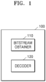
- FIG. 1 is a block diagram of the image decoding apparatus 100 for decoding an image based on at least one from among block shape information and split shape information, according to an embodiment.
- the decoder 120 of the image decoding apparatus 100 may determine a shape of the coding unit based on the block shape information.
- the block shape information may include information indicating whether the coding unit has a square shape or a non-square shape.
- the decoder 120 may determine the shape of the coding unit by using the block shape information.
- the image decoding apparatus 100 may obtain the coding unit having a size of 128x128 from the largest coding unit having a size of 256x256 based on the information about the split shape mode. Also, the image decoding apparatus 100 may determine a size of the smallest coding unit to be 4x4. The image decoding apparatus 100 may obtain the information about the split shape mode indicating "not to perform splitting" for the smallest coding unit.
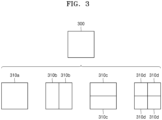
- the image decoding apparatus 100 may use the block shape information indicating that the current coding unit has a square shape. For example, the image decoding apparatus 100 may determine whether not to split a square coding unit, whether to vertically split the square coding unit, whether to horizontally split the square coding unit, or whether to split the square coding unit into four coding units, based on the information about the split shape mode. Referring to FIG.
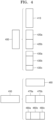
- FIG. 4 illustrates a process, performed by the image decoding apparatus 100, of determining at least one coding unit by splitting a non-square coding unit, according to an embodiment.
- the image decoding apparatus 100 may determine that a coding unit 410 or 460 having the same size as the current coding unit 400 or 450 is not split, based on the information about the split shape mode indicating not to perform splitting, or determine coding units 420a and 420b, 430a to 430c, 470a and 470b, or 480a to 480c split based on the information about the split shape mode indicating a predetermined splitting method.
- Predetermined splitting methods of splitting a non-square coding unit will be described in detail below in relation to various embodiments.
- the image decoding apparatus 100 may allow a decoding method of the coding unit 430b or 480b to be different from that of the other coding units 430a and 430c, or 480a and 480c, wherein the coding unit 430b or 480b is at a center location from among the three coding units 430a, 430b, and 430c, or 480a, 480b, and 480c generated by splitting the current coding unit 400 or 450.
- the image decoding apparatus 100 may restrict the coding unit 430b or 480b at the center location to be no longer split or to be split only a predetermined number of times, unlike the other coding units 430a and 430c, or 480a and 480c.
- the image decoding apparatus 100 may determine to split or not to split a square first coding unit 500 into coding units, based on at least one of the block shape information and the information about the split shape mode. According to an embodiment, when the information about the split shape mode indicates to split the first coding unit 500 in a horizontal direction, the image decoding apparatus 100 may determine a second coding unit 510 by splitting the first coding unit 500 in a horizontal direction.
- a first coding unit, a second coding unit, and a third coding unit used according to an embodiment are terms used to understand a relation before and after splitting a coding unit. For example, a second coding unit may be determined by splitting a first coding unit, and a third coding unit may be determined by splitting the second coding unit. It will be understood that a relationship among the first coding unit, the second coding unit, and the third coding unit follows the above descriptions.
- the second coding unit 510 may also be split into the third coding units 520a, or 520b, 520c, and 520d based on at least one of the block shape information and the information about the split shape mode of the second coding unit 510. That is, a coding unit may be recursively split based on at least one of the block shape information and the information about the split shape mode of each coding unit. Therefore, a square coding unit may be determined by splitting a non-square coding unit, and a non-square coding unit may be determined by recursively splitting the square coding unit.
- a predetermined coding unit from among an odd number of third coding units 520b, 520c, and 520d determined by splitting the non-square second coding unit 510 may be recursively split.
- the square third coding unit 520b from among the odd number of third coding units 520b, 520c, and 520d may be split in a horizontal direction into a plurality of fourth coding units.
- a non-square fourth coding unit 530b or 530d from among the plurality of fourth coding units 530a, 530b, 530c, and 530d may be split into a plurality of coding units.
- the non-square fourth coding unit 530 or 530d may be split into an odd number of coding units again.
- the image decoding apparatus 100 may split each of the third coding units 520a, or 520b, 520c, and 520d into coding units, based on at least one of the block shape information and the information about the split shape mode. Also, the image decoding apparatus 100 may determine not to split the second coding unit 510 based on at least one of the block shape information and the information about the split shape mode. According to an embodiment, the image decoding apparatus 100 may split the non-square second coding unit 510 into the odd number of third coding units 520b, 520c, and 520d. The image decoding apparatus 100 may put a predetermined restriction on a predetermined third coding unit from among the odd number of third coding units 520b, 520c, and 520d. For example, the image decoding apparatus 100 may restrict the third coding unit 520c at a center location from among the odd number of third coding units 520b, 520c, and 520d to be no longer split or to be split a settable number of times.
- the image decoding apparatus 100 may use information indicating locations of an odd number of coding units to determine a coding unit at a center location from among the odd number of coding units. Referring to FIG. 6 , the image decoding apparatus 100 may determine an odd number of coding units 620a, 620b, and 620c or an odd number of coding units 660a, 660b, and 660c by splitting the current coding unit 600 or the current coding unit 650.
- the information indicating the locations of the top left samples 630a, 630b, and 630c, which are included in the coding units 620a, 620b, and 620c, respectively may include information indicating widths or heights of the coding units 620a, 620b, and 620c included in the current coding unit 600, and the widths or heights may correspond to information indicating differences between the coordinates of the coding units 620a, 620b, and 620c in the picture.
- the image decoding apparatus 100 may determine the middle coding unit 620b, which has a size different from the size of the upper and lower coding units 620a and 620c, as the coding unit of the predetermined location.
- the above-described method, performed by the image decoding apparatus 100, of determining a coding unit having a size different from the size of the other coding units merely corresponds to an example of determining a coding unit at a predetermined location by using the sizes of coding units, which are determined based on coordinates of samples, and thus various methods of determining a coding unit at a predetermined location by comparing the sizes of coding units, which are determined based on coordinates of predetermined samples, may be used.
- the image decoding apparatus 100 may determine sizes of the coding units 660a, 660b, and 660c by using the coordinates (xd, yd), (xe, ye), and (xf, yf) indicating locations of the coding units 660a, 660b, and 660c.
- the image decoding apparatus 100 may determine the width of the left coding unit 660a to be xe-xd. The image decoding apparatus 100 may determine the height of the left coding unit 660a as the height of the current coding unit 650. According to an embodiment, the image decoding apparatus 100 may determine the width of the middle coding unit 660b to be xf-xe. The image decoding apparatus 100 may determine the height of the middle coding unit 660b to be the height of the current coding unit 600.
- the image decoding apparatus 100 may determine the width or the height of the right coding unit 660c by using the width or the height of the current coding unit 650 and the width and the height of the left coding unit 660a and the middle coding unit 660b.
- the image decoding apparatus 100 may determine a coding unit, which has a size different from that of the others, based on the determined widths and heights of the coding units 660a, 660b, and 660c.
- the image decoding apparatus 100 may determine the middle coding unit 660b, which has a size different from the size of the left coding unit 660a and the right coding unit 660c, as the coding unit of the predetermined location.
- predetermined information about a coding unit at a predetermined location may be used in a splitting operation to determine the coding unit at the predetermined location from among the plurality of coding units.
- the image decoding apparatus 100 may use at least one of block shape information and information about a split shape mode, which is stored in a sample included in a coding unit at a center location, in a splitting operation to determine the coding unit at the center location from among the plurality of coding units determined by splitting the current coding unit.
- the image decoding apparatus 100 may split the current coding unit 600 into the plurality of coding units 620a, 620b, and 620c based on at least one of the block shape information and the information about the split shape mode, and may determine the coding unit 620b at a center location from among the plurality of the coding units 620a, 620b, and 620c. Furthermore, the image decoding apparatus 100 may determine the coding unit 620b at the center location, in consideration of a location from which at least one of the block shape information and the information about the split shape mode is obtained.
- At least one of the block shape information and the information about the split shape mode of the current coding unit 600 may be obtained from the sample 640 at a center location of the current coding unit 600 and, when the current coding unit 600 is split into the plurality of coding units 620a, 620b, and 620c based on at least one of the block shape information and the information about the split shape mode, the coding unit 620b including the sample 640 may be determined as the coding unit at the center location.
- information used to determine the coding unit at the center location is not limited to at least one of the block shape information and the information about the split shape mode, and various kinds of information may be used to determine the coding unit at the center location.
- the image decoding apparatus 100 may determine the sample 640 at the center location of the current coding unit 600 as the sample from which the predetermined information may be obtained, and may put a predetermined restriction on the coding unit 620b including the sample 640, in a decoding operation.
- the location of the sample from which the predetermined information may be obtained is not limited to the above-described location, and may include arbitrary locations of samples included in the coding unit 620b to be determined for a restriction.
- a coding unit may be recursively split based on at least one of the block shape information and the information about the split shape mode, which is obtained from the sample at the predetermined location in each coding unit.
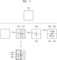
- the image decoding apparatus 100 may determine to process the second coding units 710a and 710b, which are determined by splitting the first coding unit 700 in a vertical direction, in a horizontal direction order 710c.
- the image decoding apparatus 100 may determine to process the second coding units 730a and 730b, which are determined by splitting the first coding unit 1400 in a horizontal direction, in a vertical direction order 730c.
- the right second coding unit 710b may be processed after the third coding units 720a and 720b included in the left second coding unit 710a are processed in the vertical direction order 720c.
- An operation of determining a processing order of coding units based on a coding unit before being split is not limited to the above-described example, and various methods may be used to independently process coding units, which are split and determined to various shapes, in a predetermined order.
- the image decoding apparatus 100 may determine the plurality of third coding units 820a and 820b by splitting the left second coding unit 810a in a horizontal direction, and may split the right second coding unit 810b into an odd number of third coding units 820c to 820e.
- the image decoding apparatus 100 may determine whether any of the first coding unit 800, the second coding units 810a and 810b, and the third coding units 820a and 820b, and 820c, 820d, and 820e are split into an odd number of coding units, based on at least one of the block shape information and the information about the split shape mode. For example, the right second coding unit 810b may be split into an odd number of third coding units 820c, 820d, and 820e.
- a processing order of a plurality of coding units included in the first coding unit 800 may be a predetermined order (e.g., a Z-scan order 830), and the image decoding apparatus 100 may decide whether the third coding units 820c, 820d, and 820e, which are determined by splitting the right second coding unit 810b into an odd number of coding units, satisfy a condition for processing in the predetermined order.
- a predetermined order e.g., a Z-scan order 830
- the image decoding apparatus 100 may put a predetermined restriction on a coding unit at a predetermined location among the split coding units, and the restriction or the predetermined location has been described above in relation to various embodiments and thus detailed descriptions thereof will not be provided here.
- the image decoding apparatus 100 may split the square first coding unit 900 into an odd number of coding units, e.g., second coding units 910a, 910b, and 910c determined by splitting the square first coding unit 900 in a vertical direction or second coding units 920a, 920b, and 920c determined by splitting the square first coding unit 900 in a horizontal direction.
- odd number of coding units e.g., second coding units 910a, 910b, and 910c determined by splitting the square first coding unit 900 in a vertical direction or second coding units 920a, 920b, and 920c determined by splitting the square first coding unit 900 in a horizontal direction.
- the image decoding apparatus 100 may decide disconnection of a scan order, and may determine that the first coding unit 900 is split into an odd number of coding units, based on a result of the decision. According to an embodiment, when a coding unit is split into an odd number of coding units, the image decoding apparatus 100 may put a predetermined restriction on a coding unit at a predetermined location from among the split coding units, and the restriction or the predetermined location has been described above in relation to various embodiments and thus detailed descriptions thereof will not be provided herein.
- the image decoding apparatus 100 may split the square first coding unit 900 or a non-square first coding unit 930 or 950 into various-shaped coding units.
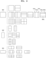
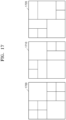
- FIG. 11 illustrates a process, performed by the image decoding apparatus 100, of splitting a square coding unit when information about a split shape mode indicates that the square coding unit is not to be split into four square coding units, according to an embodiment.
- the image decoding apparatus 100 may independently split the non-square second coding units 1110a, 1110b, 1120a, 1120b, etc.
- Each of the second coding units 1110a, 1110b, 1120a, 1120b, etc. may be recursively split in a predetermined order, and this splitting method may correspond to a method of splitting the first coding unit 1100, based on at least one of the block shape information and the information about the split shape mode.
- the image decoding apparatus 100 may determine processing orders of the third coding units 1216a, 1216b, 1216c, and 1216d, and 1226a, 1226b, 1226c, and 1226d based on a splitting method of the first coding unit 1200.
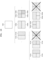
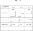
- the image decoding apparatus 100 may determine a second coding unit 1312 or 1322 and a third coding unit 1314 or 1324 of deeper depths by splitting a non-square first coding unit 1310 or 1320 based on block shape information indicating a non-square shape (for example, the block shape information may be expressed as '1: NS_VER' indicating a non-square shape, a height of which is longer than a width, or as '2: NS_HOR' indicating a non-square shape, a width of which is longer than a height).
- the image decoding apparatus 100 may determine the second coding unit 1302, 1312, or 1322 by dividing at least one of a width and height of the first coding unit 1310 having a size of N ⁇ 2N. That is, the image decoding apparatus 100 may determine the second coding unit 1302 having a size of N ⁇ N or the second coding unit 1322 having a size of N ⁇ N/2 by splitting the first coding unit 1310 in a horizontal direction, or may determine the second coding unit 1312 having a size of N/2 ⁇ N by splitting the first coding unit 1310 in horizontal and vertical directions.
- the image decoding apparatus 100 may determine the second coding unit 1302, 1312, or 1322 by dividing at least one of a width and height of the first coding unit 1320 having a size of 2N ⁇ N. That is, the image decoding apparatus 100 may determine the second coding unit 1302 having a size of N ⁇ N or the second coding unit 1312 having a size of N/2 ⁇ N by splitting the first coding unit 1320 in a vertical direction, or may determine the second coding unit 1322 having a size of N ⁇ N/2 by splitting the first coding unit 1320 in horizontal and vertical directions.
- the image decoding apparatus 100 may determine the third coding unit 1304, 1314, or 1324 by dividing at least one of a width and height of the second coding unit 1302 having a size of N ⁇ N. That is, the image decoding apparatus 100 may determine the third coding unit 1304 having a size of N/2 ⁇ N/2, the third coding unit 1314 having a size of N/4 ⁇ N/2, or the third coding unit 1324 having a size of N/2 ⁇ N/4 by splitting the second coding unit 1302 in vertical and horizontal directions.
- the image decoding apparatus 100 may determine the third coding unit 1304, 1314, or 1324 by dividing at least one of a width and height of the second coding unit 1322 having a size of N ⁇ N/2. That is, the image decoding apparatus 100 may determine the third coding unit 1304 having a size of N/2 ⁇ N/2 or the third coding unit 1314 having a size of N/4 ⁇ N/2 by splitting the second coding unit 1322 in a vertical direction, or may determine the third coding unit 1324 having a size of N/2 ⁇ N/4 by splitting the second coding unit 1322 in vertical and horizontal directions.
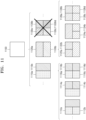
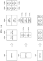
- a depth of the second coding units 1402a and 1402b, 1404a and 1404b, and 1406a, 1406b, 1406c, and 1406d which are determined based on the information about the split shape mode of the square first coding unit 1400, may be determined based on the length of a long side thereof. For example, because the length of a side of the square first coding unit 1400 equals the length of a long side of the non-square second coding units 1402a and 1402b, and 1404a and 1404b, the first coding unit 1400 and the non-square second coding units 1402a and 1402b, and 1404a and 1404b may have the same depth, e.g., D.
- the image decoding apparatus 100 may determine a plurality of second coding units 1412a and 1412b, and 1414a, 1414b, and 1414c by splitting a first coding unit 1410, a height of which is longer than a width, in a horizontal direction based on the information about the split shape mode. According to an embodiment, the image decoding apparatus 100 may determine a plurality of second coding units 1422a and 1422b, and 1424a, 1424b, and 1424c by splitting a first coding unit 1420, a width of which is longer than a height, in a vertical direction based on the information about the split shape mode.
- a depth of the second coding units 1414a, 1414b, and 1414c may be D+1 which is deeper than the depth D of the non-square first coding unit 1410 by 1.
- the image decoding apparatus 100 may determine depths of coding units split from the first coding unit 1420 having a non-square shape, a width of which is longer than a height, by using the above-described method of determining depths of coding units split from the first coding unit 1410.
- the image decoding apparatus 100 may determine whether to use a specific splitting method, based on PID values for identifying a plurality of coding units determined by splitting a current coding unit. Referring to FIG. 14 , the image decoding apparatus 100 may determine an even number of coding units 1412a and 1412b or an odd number of coding units 1414a, 1414b, and 1414c by splitting the first coding unit 1410 having a rectangular shape, a height of which is longer than a width. The image decoding apparatus 100 may use PIDs to identify respective coding units. According to an embodiment, the PID may be obtained from a sample of a predetermined location of each coding unit (e.g., a top left sample).
- the coding unit 1414b generated by splitting the first coding unit 1410 may have a width equal to that of the other coding units 1414a and 1414c and a height which is two times that of the other coding units 1414a and 1414c.
- the PID of the coding unit 1414b at the center location is 1, the PID of the coding unit 1414c located next to the coding unit 1414b may be increased by 2 and thus may be 3.
- the image decoding apparatus 100 may determine that a coding unit is split into a plurality of coding units including a coding unit having a size different from that of the other coding units.
- the image decoding apparatus 100 may split a current coding unit in such a manner that a coding unit of a predetermined location among an odd number of coding units (e.g., a coding unit of a centre location) has a size different from that of the other coding units.
- the image decoding apparatus 100 may determine the coding unit of the centre location, which has a different size, by using PIDs of the coding units.
- the PIDs and the size or location of the coding unit of the predetermined location are not limited to the above-described examples, and various PIDs and various locations and sizes of coding units may be used.
- the image decoding apparatus 100 may use a predetermined data unit where a coding unit starts to be recursively split.
- the image decoding apparatus 100 may split the current picture into a plurality of reference data units. According to an embodiment, the image decoding apparatus 100 may split the plurality of reference data units, which are split from the current picture, by using information about a split shape mode for each reference data unit.
- the operation of splitting the reference data unit may correspond to a splitting operation using a quadtree structure.
- the image decoding apparatus 100 may previously determine the minimum size allowed for the reference data units included in the current picture. Accordingly, the image decoding apparatus 100 may determine various reference data units having sizes equal to or greater than the minimum size, and may determine one or more coding units by using the block shape information and the information about the split shape mode with reference to the determined reference data unit.
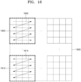
- the image decoding apparatus 100 may use a square reference coding unit 1500 or a non-square reference coding unit 1502.
- the shape and size of reference coding units may be determined based on various data units capable of including one or more reference coding units (e.g., sequences, pictures, slices, slice segments, largest coding units, or the like).
- the bitstream obtainer 110 of the image decoding apparatus 100 may obtain, from a bitstream, at least one of reference coding unit shape information and reference coding unit size information with respect to each of the various data units.
- An operation of splitting the square reference coding unit 1500 into one or more coding units has been described above in relation to the operation of splitting the current coding unit 300 of FIG. 3
- an operation of splitting the non-square reference coding unit 1502 into one or more coding units has been described above in relation to the operation of splitting the current coding unit 400 or 450 of FIG. 4 , and thus, detailed descriptions thereof will not be provided herein.
- the image decoding apparatus 100 may determine the size and shape of reference data units with respect to each data unit, which satisfies the predetermined condition, by using the PID.
- the reference coding unit shape information and the reference coding unit size information are obtained and used from the bitstream according to each data unit having a relatively small size, efficiency of using the bitstream may not be high, and therefore, only the PID may be obtained and used instead of directly obtaining the reference coding unit shape information and the reference coding unit size information.
- at least one of the size and shape of reference coding units corresponding to the PID for identifying the size and shape of reference coding units may be previously determined.
- the image decoding apparatus 100 may determine the reference coding units by splitting the largest coding unit n times based on a quadtree structure, and may split the reference coding unit based on at least one of the block shape information and the information about the split shape mode according to various embodiments.
- FIG. 16 illustrates a processing block serving as a unit for determining a determination order of reference coding units included in a picture 1600, according to an embodiment.
- the image decoding apparatus 100 may obtain block shape information indicating the shape of a current coding unit or information about a split shape mode indicating a splitting method of the current coding unit, from the bitstream, and may use the obtained information.
- the block shape information or the information about the split shape mode may be included in the bitstream related to various data units.
- the image decoding apparatus 100 may use the block shape information or the information about the split shape mode included in a sequence parameter set, a picture parameter set, a video parameter set, a slice header, or a slice segment header.
- the image decoding apparatus 100 may obtain, from the bitstream, a syntax element corresponding to the block shape information or the information about the split shape mode according to each largest coding unit, each reference coding unit, or each processing block, and may use the obtained syntax element.
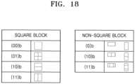
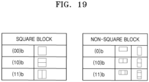
- the bitstream obtainer 110 of the image decoding apparatus 100 may obtain a bitstream including an index indicating a combination of split shape information according to predetermined data unit units (e.g., sequences, pictures, or slices).
- predetermined data unit units e.g., sequences, pictures, or slices.
- the bitstream obtainer 110 may obtain an index indicating a combination of split shape information from a sequence parameter set, a picture parameter set, or a slice header.
- the image decoding apparatus 100 may determine a combination of split shapes into which a coding unit is splittable according to predetermined data units by using the obtained index, and thus different combinations of split shapes may be used according to predetermined data units.
- split shape information when a coding unit is not split, split shape information may be represented as (00)b; when a coding unit is split in a horizontal direction and a vertical direction, split shape information may be represented as (01)b; when a coding unit is split in a horizontal direction, split shape information may be represented as (10)b; and when a coding unit is spilt in a vertical direction, split shape information may be represented as (11)b.
- a process, performed by the image decoding apparatus 100, of obtaining syntax about block shape information or split shape information through CABAC will be described.
- a bitstream including a binary code for the syntax may be obtained by the bitstream obtainer 110.
- the image decoding apparatus 100 may detect a syntax element indicating the block shape information or the split shape information by de-binarizing a bin string included in the obtained bitstream.
- the image decoding apparatus 100 may obtain a set of binary bin strings corresponding to the syntax element to be decoded and may decode each bin by using probability information, and the image decoding apparatus 100 may repeatedly perform this process until a bin string including such decoded bins is the same as one of pre-obtained bin strings.
- the image decoding apparatus 100 may determine the syntax element by de-binarizing the bin string.
- the image decoding apparatus 100 may update a probability of the bins used in a process of decoding the bins of the bin string for the syntax, and the image decoding apparatus 100 may determine that a specific bit in the bin string has the same probability without updating the probability.
- FIG. 20 is a block diagram of an image encoding and decoding system 2000 for performing loop filtering.
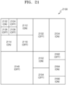
- FIG. 21 illustrates an example of filtering units included in a largest coding unit and filtering performance information of a filtering unit, according to an embodiment.
- the filtering units may include a filtering unit 2140 having a square shape and a depth of D, filtering units 2132 and 2134 having a non-square shape and a depth of D, filtering units 2112, 2114, 2116, 2152, 2154, and 2164 having a square shape and a depth of D+1, filtering units 2162 and 2166 having a non-square shape and a depth of D+1, and filtering units 2122, 2124, 2126, and 2128 having a square shape and a depth of D+2.
- a filtering unit 2140 having a square shape and a depth of D
- filtering units 2132 and 2134 having a non-square shape and a depth of D
- filtering units 2112, 2114, 2116, 2152, 2154, and 2164 having a square shape and a depth of D+1
- filtering units 2162 and 2166 having a non-square shape and a depth of D+1
- filtering units 2122, 2124, 2126, and 2128 having
- a filtering unit is determined based on a coding unit according to an embodiment, a filtering unit may be split based on a coding unit until an arbitrary depth, and thus a shape of the filtering unit may be determined up to only the arbitrary depth.
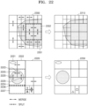
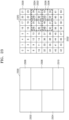
- FIG. 23 illustrates an index according to a Z-scan order of a coding unit according to an embodiment.
- the image decoding apparatus 100 may scan lower data units included in an upper data unit according to a Z-scan order. Also, the image decoding apparatus 100 according to an embodiment may sequentially access data according to a Z-scan index in a coding unit included in a processing block or a largest coding unit.
- the image decoding apparatus 100 may split a reference coding unit into at least one coding unit as described with reference to FIGS. 13 and 14 .
- coding units having a square shape and coding units having a non-square shape may co-exist in the reference coding unit.
- the image decoding apparatus 100 may access data according to a Z-scan index included in each coding unit in the reference coding unit.
- a method of applying a Z-scan index may vary according to whether a coding unit having a non-square shape exists in the reference coding unit.
- coding units of a lower depth in the reference coding unit may have continuous Z-scan indices.
- a coding unit of an upper depth may include four coding units of a lower depth. Boundaries of the four coding units of the lower depth may be continuous, and the coding units of the lower depth may be scanned in a Z-scan order according to indices indicating the Z-scan order.
- the indices indicating the Z-scan order may be set to numbers that increase according to the Z-scan order for the coding units. In this case, deeper coding units of the same depth may be scanned according to the Z-scan order.
- the image decoding apparatus 100 may split each of the coding units in the reference coding unit into sub-blocks, and may scan the split sub-blocks according to the Z-scan order. For example, when a coding unit having a non-square shape in a vertical direction or a horizontal direction exists in the reference coding unit, Z-scan may be performed by using split sub-blocks. Also, for example, when the reference coding unit is split into an odd number of coding units, Z-scan may be performed by using sub-blocks.
- a sub-block is a coding unit that is no longer split or a coding unit obtained by splitting an arbitrary coding unit, and may have a square shape.
- four sub-blocks having a square shape may be split from a coding unit having a square shape.
- two sub-blocks having a square shape may be split from a coding unit having a non-square shape.
- the sub-blocks 2322 and 2324 may be scanned after data processing is performed on a sub-block 2330, and the sub-blocks 2326 and 2328 may be scanned after data processing is performed on a sub-block 2332. Also, the sub-blocks may be scanned according to the Z-scan order.
- data units are scanned according to a Z-scan order for data storage, data loading, and data accessing.
- the image decoding apparatus 100 may generate prediction data by performing inter prediction or intra prediction on a coding unit, may generate residual data by performing inverse transformation on a transform unit included in a current coding unit, and may reconstruct the current coding unit by using the generated prediction data and the residual data.
- a prediction mode of a coding unit may be at least one of an intra mode, an inter mode, and a skip mode. According to an embodiment, a prediction mode may be independently selected according to coding units.
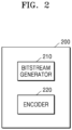
- the bitstream generator 210 may generate a bitstream based on the encoded input image. For example, the bitstream generator 210 may generate the bitstream by entropy encoding the syntax element based on the context model. Also, the image encoding apparatus 200 may transmit the bitstream to the image decoding apparatus 100.
- the encoder 220 may determine whether the coding unit is split or not split. When the encoder determines that only one coding unit is included in the coding unit or the coding unit is not split, the bitstream generator 210 may generate the bitstream including the split shape information indicating that the coding unit is not split. Also, the encoder 220 may split the coding unit into a plurality of coding units, and the bitstream generator 210 may generate the bitstream including the split shape information indicating that the coding unit is split into the plurality of coding units.
- the image encoding apparatus 200 may determine the context model further based on block shape information including at least one from among a ratio or a size of a shape, a direction, a width, and a height of a neighboring coding unit adjacent to the coding unit.
- the neighboring coding unit may include at least one from among coding units located at a left lower side, a left side, a left upper side, an upper side, a right upper side, a right side, or a right lower side of the coding unit.
- the image encoding apparatus 200 may compare a length of a width of an upper neighboring coding unit with a length of the width of the coding unit. Also, the image encoding apparatus 200 may compare a length of a height of left and right neighboring coding units with a length of the height of the coding unit. Also, the image encoding apparatus 200 may determine the context model based on comparison results.
- An operation of the image encoding apparatus 200 is similar to an operation of the image decoding apparatus 100 described with reference to FIGS. 13 through 34 , and thus a detailed explanation thereof is not provided here.
- the motion vector decoding apparatus 2500 may be included in the image decoding apparatus 100 described above.
- the bitstream obtainer 2510 may be included in the bitstream obtainer 110 of the image decoding apparatus 100 illustrated in FIG. 1 and the default motion vector determiner 2530 and the prediction decoder 2550 may be included in the decoder 120 of the image decoding apparatus 100.
- a type of a block may be a square shape or a rectangular shape, or may be an arbitrary geometrical shape.
- a block according to an embodiment is not limited to a data unit of a certain size, and may include a largest coding unit, a coding unit, a prediction unit, and a transform unit from among coding units according to a tree structure.
- the default MV may be a spare MV for an MV of the PMV candidate block used for determining the PMV of the current block.
- FIG. 29 illustrates spatial blocks and temporal blocks associated with a current block 2900.
- the spatial blocks spatially associated with the current block 2900 may include a left upper block a, a right upper block b, an upper left block c, an upper right block d, a left upper outer block e, a right upper outer block f, a left lower outer block g, a right lower outer block h, a left lower block i, a right lower block j, a lower left block k, a lower right block I, a left block m, a right block n, an upper block o, and a lower block p.
- the default motion vector determiner 2530 may determine whether or not each default MV candidate block has an MV according to the priority order and may determine the MV of the default MV candidate block for which the availability of the MV is first identified, as the default MV.
- the default motion vector determiner 2530 may change the priority order that is set with respect to the plurality of default MV candidate blocks by comparing a reference image index of the current block with a reference image index of the plurality of default MV candidate blocks. For example, the default motion vector determiner 2530 may increase the priority order of a default MV candidate block having a reference image index that is the same as the reference image index of the current block. When there are a plurality of default MV candidate blocks having the same reference image index as the current block, an order among the plurality of default MV candidate blocks may comply with the predetermined priority order.
- the priority order of the block C5 may be changed to be the first. Accordingly, the priority order may be changed to have an order of the block C5, C0, C1, C2, C3, and C4. Also, for example, when the priority order is set in the order of the block C0 to the block C5 and a reference image index of the block C4 and the reference image index of the block C5 are the same as the reference image index of the current block, the priority orders of the blocks C4 and C5 may be increased. In addition, the priority order may be changed in an order of the blocks C4, C5, C0, C1, C2, and C34 such that the priority order of the block C4 is higher than the priority order of the block C5 according to the initial priority order.
- the default motion vector determiner 2530 may determine the default MV corresponding to a specific direction from a default MV candidate block located in the specific direction based on the current block. For example, when the default motion vector determiner 2530 is to determine the default MV corresponding to a left direction, the default motion vector determiner 2530 may determine the default MV based on the MV of a default MV candidate block located in the left direction based on the current block. Also, for example, when the default motion vector determiner 2530 is to determine the default MV corresponding to an upper direction, the default motion vector determiner 2530 may determine the default MV based on the MV of a default MV candidate block located in the upper direction based on the current block.
- the default motion vector determiner 2530 may determine the default MV by using the MV of the block C0.
- the default motion vector determiner 2530 may select a plurality of default MV candidate blocks according to an order in which the default MV candidate blocks are selected as the PMV in the previously decoded picture, slice, or largest coding unit, and may determine the plurality of default MVs by using the MVs of the selected default MV candidate blocks.
- the default motion vector determiner 2530 may scale the MV of the at least one default MV candidate block by taking into account the reference image index of the current block and determine the scaled MV as the default MV.
- the default motion vector determiner 2530 may determine the default MV of the current block by using an MV derived via decoder side MV derivation (DMVD).
- the DMVD may include, for example, a template matching method or a bilateral matching method.
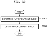
- the prediction decoder 2550 may determine a PMV of the current block by using an MV of at least one PMV candidate block.
- the PMV of the current block may include a previously decoded spatial block and/or a previously decoded temporal block associated with the current block.
- the at least one PMV candidate block may be selected from among the blocks spatially associated with the current block and the blocks temporally associated with the current block illustrated in FIG. 29 .
- the prediction decoder 2550 may determine an availability of an MV of the at least one PMV candidate block, and when there is a PMV candidate block determined not to be available, the prediction decoder 2550 may determine the PMV of the current block by using the default MV.
- the number of prediction candidates to be included in the prediction candidate list may be predetermined.
- the default motion vector determiner 2530 may determine the default MVs of numbers corresponding to the predetermined number of prediction candidates to be included in the prediction candidate list.
- the prediction decoder 2550 may determine the availability of each of the PMV candidate blocks and assign the default MV to a PMV candidate block determined not to be available. Then, the prediction decoder 2550 may construct the prediction candidate list according to the priority order of the PMV candidate blocks. For example, the prediction decoder 2550 may determine the availability of the blocks A0 to H of FIG. 31 , and when the block A1 is determined not to be available, may assign the default MV to the block A1. Then, the prediction decoder 2550 may include the MV of each of the blocks A0 to H in the prediction candidate list according to the priority order.
- the default motion vector determiner 2530 may determine the same number of default MVs as the number of PMV candidate blocks in the predetermined location.
- the prediction decoder 2550 may assign the default MV to the block D1. Also, in the method of determining the PMV of the current block by using the MVs of the blocks D1, D2, and D3, when there are no MVs in the blocks D1 and D2, the prediction decoder 2550 may assign default MVs to the blocks D1 and D2, respectively.
- the bitstream obtainer 2510 may obtain information about the MVR for each inter-predicted coding unit.
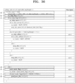
- FIG. 36 illustrates a syntax for obtaining information about an MVR from a bitstream.
- pred_mvr_idx is extracted in a phrase g.
- pred_mvr_idx is an index indicating an MVR of the current coding unit, and an MVR corresponding to each index is as shown in Table 2.
- Table 2 MVR Index 0 1 2 3 4 Resolution (R) in pel 1/4 1/2 1 2 4
- the default MV may have to be adjusted.
- the number of the PMV candidate blocks used to determine the PMV is one and the PMV candidate block is available, and when the number of the PMV candidate blocks used to determine the PMV is more than one, and one or more of the plurality of PMV candidate blocks are available, the MVs of the PMV candidate blocks that are available may be used to determine the PMV.
- the MV of the PMV candidate block determined to be available also may have to be adjusted like the default MV.
- the prediction decoder 2550 may obtain an MV of the current block from the PMV.
- a prediction mode of the current block is a skip mode or a merge mode
- the prediction decoder 2550 may determine the PMV as the MV of the current block and when the prediction mode of the current block is an advanced motion vector prediction (AMVP) mode, the prediction decoder 2550 may obtain the MV of the current block by combining a residual MV and the PMF.
- AMVP advanced motion vector prediction
- the prediction decoder 2550 may upscale a residual MV obtained from a bitstream by comparing the MVR of the current block with the minimum MVR, and may obtain the MV of the current block by combining the upscaled residual MV and the PMV.
- the upscaling of the residual MV will be described below.
- the motion vector decoding apparatus 2500 may determine an availability of an MV of the at least one PMV candidate block. When there is a PMV candidate block determined not to be available, the motion vector decoding apparatus 2500 may determine the PMV of the current block by using a default MV determined from a plurality of default MV candidate blocks.
- the motion vector decoding apparatus 2500 may determine the PMV of the current block by using a default MV adjusted according to the MVR of the current block.
- the default motion vector determiner 2710 may determine one default MV or a plurality of default MVs based on an MV of a plurality of default MV candidate blocks associated with the current block.
- the default motion vector determiner 2710 may set a priority order with respect to the default MV candidate blocks and may determine whether or not there is an MV with respect to each of the default MV candidate blocks according to the priority order.
- the default motion vector determiner 2710 may determine at least one default MV based on the MV of the at least one default MV candidate block, according to an order in which it is identified that the MV exists.
- the default motion vector determiner 2710 may determine whether or not each default MV candidate block has an MV according to the priority order and may determine the MV of the default MV candidate block for which the availability of the MV is first identified, as the default MV.
- the default motion vector determiner 2710 may change the priority order that is set with respect to the plurality of default MV candidate blocks by comparing a reference image index of the current block with a reference image index of the plurality of default MV candidate blocks. For example, the default motion vector determiner 2710 may increase the priority order of a default MV candidate block having a reference image index that is the same as the reference image index of the current block. When there are a plurality of default MV candidate blocks having the same reference image index as the current block, an order among the plurality of default MV candidate blocks may comply with the predetermined priority order.
- the default motion vector determiner 2710 may determine whether or not the reference image index of each default MV candidate block is the same as the reference image index of the current block according to the priority order and may determine the MV of at least one default MV candidate block as at least one default MV according to an order in which it is determined that the reference image index is the same as the reference image index of the current block.
- the default motion vector determiner 2710 may determine whether each default MV candidate block has an MV according to the priority order and may determine the MV of at least one default MV candidate block as at least one default MV, according to the order in which it is identified that the MV exists.
- the default motion vector determiner 2710 may determine the MVs of one more default MV candidate blocks having the same reference image index as the current block as the default MVs, regardless of whether or not the priority order is set.
- the default motion vector determiner 2710 may select a predetermined number of default MV candidate blocks based on an order in which the default MV candidate blocks have a smaller MV, and may determine the MVs of the selected predetermined number of default MV candidate blocks as the default MV.
- the default motion vector determiner 2710 may determine, as the default MV, the MV of a default MV candidate block from among the at least one default MV candidate block, the default MV candidate block being in a location most frequently selected for a PMV in a previously encoded picture, a previously encoded slice, or a previously encoded largest coding unit.
- the default motion vector determiner 2710 may select a plurality of default MV candidate blocks according to an order in which the default MV candidate blocks are selected as the PMV in the previously encoded picture, slice, or largest coding unit, and may determine the plurality of default MVs by using the MVs of the selected default MV candidate blocks.
- the default motion vector determiner 2710 when the default motion vector determiner 2710 determines the default MV by using the MV of at least one default MV candidate block selected based on a certain criteria from among the plurality of default MV candidate blocks, the default motion vector determiner 2710 may intactly determine the MV of the at least one default MV candidate block as the default MV, or may change the MV of the at least one default MV candidate block and determine the changed MV as the default MV.
- the default motion vector determiner 2710 may scale the MV of the at least one default MV candidate block by taking into account the reference image index of the current block and determine the scaled MV as the default MV.
- the prediction encoder 2730 may interpolate the reference image by using the 1/4-pixel unit which has the minimum MVR and may determine the MV by using the 1-pixel unit in the interpolated reference image.
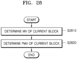
- the prediction encoder 2730 may determine a PMV of the current block in order to encode the MV of the current block.
- the PMV of the current block may be determined from at least one PMV candidate block including spatial blocks and/or temporal blocks associated with the current block.
- the number and the location of the PMV candidate blocks may be predetermined in the prediction encoder 2730 or may be determined by the prediction encoder 2730 for a picture unit, a slice unit, or a block unit. According to an embodiment, the number and the location of the PMV candidate blocks may be determined according to the MVR of the current block.
- the prediction encoder 2730 may determine an availability of an MV of the at least one PMV candidate block, and when there is a PMV candidate block determined not to be available, the prediction encoder 2730 may determine the PMV of the current block by using the default MV.
- the prediction encoder 2730 may determine the PMV of the current block based on an MV of at least one PMV candidate block in a predetermined location.
- the prediction encoder 2730 may determine an availability of the at least one PMV candidate block in the predetermined location and may assign the default MV as the MV of a PMV candidate block determined not to be available.
- a default MV may be assigned as the MV of the block D2.
- the prediction encoder 2730 may assign the default MV to a PMV candidate block having no availability from among the PMV candidate blocks in the predetermined location, and when there are a plurality of PMV candidate blocks having no availability, the prediction decoder 2550 may assign a plurality of default MVs to the plurality of PMV candidate blocks having no availability, respectively.
- the default motion vector determiner 2530 may determine the same number of default MVs as the PMV candidate blocks in the predetermined location.
- the prediction encoder 2730 may omit obtaining the residual MV, and when the prediction mode of the current block is an AMVP mode, the prediction encoder 2730 may obtain the residual MV.
- the prediction encoder 2730 may generate information about the PMV of the current block. For example, when the PMV of the current block is determined from a predetermined number of prediction candidate lists, the prediction encoder 2730 may generate information indicating which prediction candidate from among the predetermined number of prediction candidates is used as the PMV of the current block.
- the prediction encoder 2730 may generate information indicating that the default MV is determined in order to determine the PMV of the current block. For example, when the default MV is determined by the default motion vector determiner 2710, flag 1 may be generated, and when determining of the default MV is omitted, flag 0 may be generated.
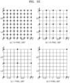
- FIG. 33 illustrates positions of pixels that may be indicated by MVs according to an MVR of a 1/4-pixel unit, an MVR of a 1/2-pixel unit, an MVR of a 1-pixel unit, and an MVR of a 2-pixel unit, when a minimum MVR selectable with respect to the current block is the MVR of the 1/4-pixel unit.
- the coordinates of the pixel that may be indicated by the MV of the MVR of the 1/4-pixel unit become (a/4, b/4) (a and b are integers)
- the coordinates of the pixel that may be indicated by the MV of the MVR of the 1/2-pixel unit become (2c/4, 2d/4) (c and d are integers)
- the coordinates of the pixel that may be indicated by the MV of the MVR of the 1-pixel unit become (4e/4, 4f/4) (e and f are integers)
- the coordinates of the pixel that may be indicated by the MV of the MVR of the 2-pixel unit become (8g/4, 8h/4) (g and h are integers).
- the motion vector encoding apparatus 2700 determines the MV in the image interpolated according to the minimum MVR, in order to represent the MV by using an integer, the MV of an integer unit may be represented by multiplying the MV by a reciprocal of a pixel unit value of the minimum MVR, for example, 2 -m when the minimum MVR has a 2 m (m is an integer) pixel unit.
- the MV of the integer unit multiplied by 2 -m may be used in the motion vector encoding apparatus 2700 and the motion vector decoding apparatus 2500.
- the motion vector encoding apparatus 2700 and the motion vector decoding apparatus 2500 may adjust the default MV to indicate neighboring pixels instead of a pixel indicated by the default MV.
- the motion vector encoding apparatus 2700 and the motion vector decoding apparatus 2500 may adjust the downscaled default MV to indicate coordinates located at the left bottom, coordinates located at the left top, or coordinates located at the right bottom.
- the motion vector encoding apparatus 2700 and the motion vector decoding apparatus 2500 may cause the adjusted default MV to indicate an integer pixel located at the left or the right of the pixel indicated by the default MV before adjustment.
- the motion vector encoding apparatus 2700 and the motion vector decoding apparatus 2500 may adjust the default MV according to Equation 1 below.
- default MV ′ default MV ⁇ k + offset ⁇ k
- Equation 1 >> or ⁇ that is a bit shift operation refers to an operation of reducing or increasing a size of the default MV.
- offset denotes a value added or subtracted to indicate an integer pixel when the default MV downscaled according to a k value does not indicate an integer pixel. offset may be differently determined according to each of an x-coordinate value and a y-coordinate value of the default MV.
- the motion vector encoding apparatus 2700 and the motion vector decoding apparatus 2500 may change the downscaled default MV according to the same criterion.
- the motion vector encoding apparatus 2700 and the motion vector decoding apparatus 2500 may omit downscaling and upscaling of the default MV, and may adjust the default MV in a coordinate plane in a reference image interpolated according to the minimum MVR to indicate a pixel unit corresponding to the MVR of the current block.
- the motion vector encoding apparatus 2700 and the motion vector decoding apparatus 2500 may adjust the default MV according to Equation 2 below, instead of Equation 1.
- default MV ′ default MV + offset ⁇ k ⁇ k
- the motion vector encoding apparatus 2700 may calculate the downscaled residual MV according to Equation 5 below, instead of Equation 3 and Equation 4.
- MVD ′ MV ⁇ PMV / R * S
- the motion vector decoding apparatus 2500 may reconstruct the MV of the current block by using the PMV of the current block and the residual MV.
- the motion vector decoding apparatus 2500 may upscale residual motion data as shown in Equation 6 below.
- MVD " MVD ′ ⁇ k
- the motion vector decoding apparatus 2500 may determine the upscaled residual MV according to Equation 7 below, instead of Equation 6 above.
- MVD " MVD ′ * R * S
Landscapes
- Engineering & Computer Science (AREA)
- Multimedia (AREA)
- Signal Processing (AREA)
- Compression Or Coding Systems Of Tv Signals (AREA)
Applications Claiming Priority (3)
| Application Number | Priority Date | Filing Date | Title |
|---|---|---|---|
| US201762557819P | 2017-09-13 | 2017-09-13 | |
| PCT/KR2018/003801 WO2019054591A1 (ko) | 2017-09-13 | 2018-03-30 | 기본 움직임 벡터를 이용하여 움직임 벡터를 부호화하는 장치 및 방법, 및 복호화 장치 및 방법 |
| EP18856771.3A EP3637773A4 (de) | 2017-09-13 | 2018-03-30 | Vorrichtung und verfahren zur codierung eines bewegungsvektors unter verwendung eines basisbewegungsvektors sowie decodierungsvorrichtung und -verfahren |
Related Parent Applications (1)
| Application Number | Title | Priority Date | Filing Date |
|---|---|---|---|
| EP18856771.3A Division EP3637773A4 (de) | 2017-09-13 | 2018-03-30 | Vorrichtung und verfahren zur codierung eines bewegungsvektors unter verwendung eines basisbewegungsvektors sowie decodierungsvorrichtung und -verfahren |
Publications (2)
| Publication Number | Publication Date |
|---|---|
| EP4539461A2 true EP4539461A2 (de) | 2025-04-16 |
| EP4539461A3 EP4539461A3 (de) | 2025-06-25 |
Family
ID=65722910
Family Applications (2)
| Application Number | Title | Priority Date | Filing Date |
|---|---|---|---|
| EP25160193.6A Pending EP4539461A3 (de) | 2017-09-13 | 2018-03-30 | Vorrichtung und verfahren zur codierung eines bewegungsvektors unter verwendung eines basisbewegungsvektors sowie decodierungsvorrichtung und -verfahren |
| EP18856771.3A Ceased EP3637773A4 (de) | 2017-09-13 | 2018-03-30 | Vorrichtung und verfahren zur codierung eines bewegungsvektors unter verwendung eines basisbewegungsvektors sowie decodierungsvorrichtung und -verfahren |
Family Applications After (1)
| Application Number | Title | Priority Date | Filing Date |
|---|---|---|---|
| EP18856771.3A Ceased EP3637773A4 (de) | 2017-09-13 | 2018-03-30 | Vorrichtung und verfahren zur codierung eines bewegungsvektors unter verwendung eines basisbewegungsvektors sowie decodierungsvorrichtung und -verfahren |
Country Status (6)
| Country | Link |
|---|---|
| US (3) | US11589070B2 (de) |
| EP (2) | EP4539461A3 (de) |
| KR (5) | KR102414679B1 (de) |
| CN (3) | CN111095925B (de) |
| MX (3) | MX2020001665A (de) |
| WO (1) | WO2019054591A1 (de) |
Families Citing this family (3)
| Publication number | Priority date | Publication date | Assignee | Title |
|---|---|---|---|---|
| US11683501B2 (en) * | 2019-01-17 | 2023-06-20 | Tencent America LLC | Method and apparatus for video coding |
| BR112021025804A2 (pt) * | 2019-06-27 | 2022-02-08 | Samsung Electronics Co Ltd | Método de decodificação de vídeo, método de codificação de vídeo, e aparelho de decodificação de vídeo |
| KR102297479B1 (ko) | 2020-04-10 | 2021-09-03 | 삼성전자주식회사 | 움직임 벡터의 부호화 장치 및 방법, 및 움직임 벡터의 복호화 장치 및 방법 |
Family Cites Families (19)
| Publication number | Priority date | Publication date | Assignee | Title |
|---|---|---|---|---|
| KR20050026661A (ko) * | 2003-09-09 | 2005-03-15 | 엘지전자 주식회사 | 디지탈 동영상 해상도 감축을 위한 움직임 벡터 설정방법 |
| EP1730968A2 (de) * | 2004-04-02 | 2006-12-13 | THOMSON Licensing | Verfahren und vorrichtung für einen komplexitätsskalierbaren videocodierer |
| KR101369746B1 (ko) * | 2007-01-22 | 2014-03-07 | 삼성전자주식회사 | 적응적 보간 필터를 이용한 영상 부호화, 복호화 방법 및장치 |
| EP1983759A1 (de) * | 2007-04-19 | 2008-10-22 | Matsushita Electric Industrial Co., Ltd. | Schätzung von separierbaren adaptiven Interpolationsfiltern für hybride Videokodierung |
| KR101356613B1 (ko) * | 2009-08-21 | 2014-02-06 | 에스케이텔레콤 주식회사 | 적응적 움직임 벡터 해상도를 이용한 영상 부호화/복호화 방법 및 장치 |
| BR112012020856A2 (pt) | 2010-02-23 | 2019-09-24 | Nippon Telegraph & Telephone | ver anexo. |
| US9509995B2 (en) | 2010-12-21 | 2016-11-29 | Intel Corporation | System and method for enhanced DMVD processing |
| KR101377528B1 (ko) * | 2011-01-15 | 2014-03-27 | 에스케이텔레콤 주식회사 | 움직임 벡터 부호화/복호화 방법 및 장치 |
| US9319716B2 (en) * | 2011-01-27 | 2016-04-19 | Qualcomm Incorporated | Performing motion vector prediction for video coding |
| HRP20230425T1 (hr) * | 2011-03-21 | 2023-07-07 | Lg Electronics, Inc. | Odabir prediktora vektora kretanja |
| US20120320936A1 (en) | 2011-06-20 | 2012-12-20 | Si-Ware Systems | Mems based swept laser source |
| KR101423648B1 (ko) * | 2011-09-09 | 2014-07-28 | 주식회사 케이티 | 화면 간 예측 수행시 후보 블록 결정 방법 및 이러한 방법을 사용하는 장치 |
| KR20130030181A (ko) | 2011-09-16 | 2013-03-26 | 한국전자통신연구원 | 움직임 벡터 예측기를 이용한 움직임 벡터 부호화/복호화 방법 및 장치 |
| KR101854003B1 (ko) * | 2013-07-02 | 2018-06-14 | 경희대학교 산학협력단 | 복수의 레이어를 포함하는 영상의 부호화 및 복호화 방법 |
| GB2524476B (en) * | 2014-03-14 | 2016-04-27 | Canon Kk | Method, device and computer program for optimizing transmission of motion vector related information when transmitting a video stream |
| GB201409634D0 (en) * | 2014-05-30 | 2014-07-16 | Canon Kk | Intra block copy mode encoding choice |
| JP6837965B2 (ja) * | 2014-10-31 | 2021-03-03 | サムスン エレクトロニクス カンパニー リミテッド | 符号化装置及び復号装置 |
| US10148963B2 (en) * | 2016-09-23 | 2018-12-04 | Arm Limited | Methods of and apparatus for encoding data arrays |
| KR20180043151A (ko) * | 2016-10-19 | 2018-04-27 | 에스케이텔레콤 주식회사 | 영상 부호화 또는 복호화를 위한 장치 및 방법 |
-
2018
- 2018-03-30 MX MX2020001665A patent/MX2020001665A/es unknown
- 2018-03-30 EP EP25160193.6A patent/EP4539461A3/de active Pending
- 2018-03-30 CN CN201880056184.XA patent/CN111095925B/zh active Active
- 2018-03-30 KR KR1020217008313A patent/KR102414679B1/ko active Active
- 2018-03-30 KR KR1020227021151A patent/KR102480419B1/ko active Active
- 2018-03-30 WO PCT/KR2018/003801 patent/WO2019054591A1/ko not_active Ceased
- 2018-03-30 EP EP18856771.3A patent/EP3637773A4/de not_active Ceased
- 2018-03-30 CN CN202310357043.4A patent/CN116389748B/zh active Active
- 2018-03-30 KR KR1020227044580A patent/KR102574479B1/ko active Active
- 2018-03-30 US US16/634,400 patent/US11589070B2/en active Active
- 2018-03-30 CN CN202310356867.XA patent/CN116389747A/zh active Pending
- 2018-03-30 KR KR1020207003361A patent/KR102185370B1/ko active Active
- 2018-03-30 KR KR1020207033587A patent/KR102232245B1/ko active Active
-
2020
- 2020-02-11 MX MX2023011668A patent/MX2023011668A/es unknown
- 2020-02-11 MX MX2023011666A patent/MX2023011666A/es unknown
-
2023
- 2023-01-12 US US18/153,879 patent/US12132924B2/en active Active
-
2024
- 2024-09-24 US US18/894,982 patent/US20250016356A1/en active Pending
Also Published As
| Publication number | Publication date |
|---|---|
| KR102414679B1 (ko) | 2022-06-29 |
| CN111095925B (zh) | 2023-04-14 |
| WO2019054591A1 (ko) | 2019-03-21 |
| KR20200023650A (ko) | 2020-03-05 |
| KR20220088817A (ko) | 2022-06-28 |
| US20230164346A1 (en) | 2023-05-25 |
| KR20200133835A (ko) | 2020-11-30 |
| KR102232245B1 (ko) | 2021-03-25 |
| US20250016356A1 (en) | 2025-01-09 |
| MX2023011666A (es) | 2023-10-18 |
| US11589070B2 (en) | 2023-02-21 |
| CN116389748B (zh) | 2025-07-22 |
| MX2023011668A (es) | 2023-10-18 |
| CN116389747A (zh) | 2023-07-04 |
| KR20230003415A (ko) | 2023-01-05 |
| EP3637773A1 (de) | 2020-04-15 |
| EP4539461A3 (de) | 2025-06-25 |
| KR20210034117A (ko) | 2021-03-29 |
| EP3637773A4 (de) | 2020-07-29 |
| CN111095925A (zh) | 2020-05-01 |
| MX2020001665A (es) | 2020-03-20 |
| KR102574479B1 (ko) | 2023-09-04 |
| US12132924B2 (en) | 2024-10-29 |
| KR102185370B1 (ko) | 2020-12-01 |
| CN116389748A (zh) | 2023-07-04 |
| US20200177908A1 (en) | 2020-06-04 |
| KR102480419B1 (ko) | 2022-12-22 |
Similar Documents
| Publication | Publication Date | Title |
|---|---|---|
| EP3618435A1 (de) | Vorrichtung und verfahren zur mittels adaptiver bewegungsvektorauflösung bestimmter bewegungsvektorkodierung sowie vorrichtung und verfahren zum decodieren eines bewegungsvektors | |
| CN111386705B (zh) | 用于对运动信息进行编码的设备和方法以及解码设备和方法 | |
| KR102285739B1 (ko) | 움직임 벡터 해상도에 기초하여 영상을 부호화하는 장치 및 방법, 및 복호화 장치 및 방법 | |
| EP4539461A2 (de) | Vorrichtung und verfahren zur codierung eines bewegungsvektors unter verwendung eines basisbewegungsvektors sowie decodierungsvorrichtung und -verfahren | |
| CN112703731A (zh) | 基于子块对图像进行编码的方法和装置以及对图像进行解码的方法和装置 |
Legal Events
| Date | Code | Title | Description |
|---|---|---|---|
| PUAI | Public reference made under article 153(3) epc to a published international application that has entered the european phase |
Free format text: ORIGINAL CODE: 0009012 |
|
| STAA | Information on the status of an ep patent application or granted ep patent |
Free format text: STATUS: REQUEST FOR EXAMINATION WAS MADE |
|
| 17P | Request for examination filed |
Effective date: 20250226 |
|
| AC | Divisional application: reference to earlier application |
Ref document number: 3637773 Country of ref document: EP Kind code of ref document: P |
|
| AK | Designated contracting states |
Kind code of ref document: A2 Designated state(s): AL AT BE BG CH CY CZ DE DK EE ES FI FR GB GR HR HU IE IS IT LI LT LU LV MC MK MT NL NO PL PT RO RS SE SI SK SM TR |
|
| REG | Reference to a national code |
Ref country code: DE Ref legal event code: R079 Free format text: PREVIOUS MAIN CLASS: H04N0019523000 Ipc: H04N0019520000 |
|
| PUAL | Search report despatched |
Free format text: ORIGINAL CODE: 0009013 |
|
| AK | Designated contracting states |
Kind code of ref document: A3 Designated state(s): AL AT BE BG CH CY CZ DE DK EE ES FI FR GB GR HR HU IE IS IT LI LT LU LV MC MK MT NL NO PL PT RO RS SE SI SK SM TR |
|
| RIC1 | Information provided on ipc code assigned before grant |
Ipc: H04N 19/70 20140101ALN20250521BHEP Ipc: H04N 19/523 20140101ALI20250521BHEP Ipc: H04N 19/52 20140101AFI20250521BHEP |