EP4539232A1 - Batterie und batteriepack sowie fahrzeug damit - Google Patents
Batterie und batteriepack sowie fahrzeug damit Download PDFInfo
- Publication number
- EP4539232A1 EP4539232A1 EP23843393.2A EP23843393A EP4539232A1 EP 4539232 A1 EP4539232 A1 EP 4539232A1 EP 23843393 A EP23843393 A EP 23843393A EP 4539232 A1 EP4539232 A1 EP 4539232A1
- Authority
- EP
- European Patent Office
- Prior art keywords
- battery
- thermal conductive
- present disclosure
- beading
- conductive member
- Prior art date
- Legal status (The legal status is an assumption and is not a legal conclusion. Google has not performed a legal analysis and makes no representation as to the accuracy of the status listed.)
- Pending
Links
Images


Classifications
-
- H—ELECTRICITY
- H01—ELECTRIC ELEMENTS
- H01M—PROCESSES OR MEANS, e.g. BATTERIES, FOR THE DIRECT CONVERSION OF CHEMICAL ENERGY INTO ELECTRICAL ENERGY
- H01M10/00—Secondary cells; Manufacture thereof
- H01M10/60—Heating or cooling; Temperature control
- H01M10/65—Means for temperature control structurally associated with the cells
- H01M10/653—Means for temperature control structurally associated with the cells characterised by electrically insulating or thermally conductive materials
-
- H—ELECTRICITY
- H01—ELECTRIC ELEMENTS
- H01M—PROCESSES OR MEANS, e.g. BATTERIES, FOR THE DIRECT CONVERSION OF CHEMICAL ENERGY INTO ELECTRICAL ENERGY
- H01M10/00—Secondary cells; Manufacture thereof
- H01M10/04—Construction or manufacture in general
-
- H—ELECTRICITY
- H01—ELECTRIC ELEMENTS
- H01M—PROCESSES OR MEANS, e.g. BATTERIES, FOR THE DIRECT CONVERSION OF CHEMICAL ENERGY INTO ELECTRICAL ENERGY
- H01M10/00—Secondary cells; Manufacture thereof
- H01M10/04—Construction or manufacture in general
- H01M10/0431—Cells with wound or folded electrodes
-
- H—ELECTRICITY
- H01—ELECTRIC ELEMENTS
- H01M—PROCESSES OR MEANS, e.g. BATTERIES, FOR THE DIRECT CONVERSION OF CHEMICAL ENERGY INTO ELECTRICAL ENERGY
- H01M10/00—Secondary cells; Manufacture thereof
- H01M10/60—Heating or cooling; Temperature control
- H01M10/61—Types of temperature control
- H01M10/613—Cooling or keeping cold
-
- H—ELECTRICITY
- H01—ELECTRIC ELEMENTS
- H01M—PROCESSES OR MEANS, e.g. BATTERIES, FOR THE DIRECT CONVERSION OF CHEMICAL ENERGY INTO ELECTRICAL ENERGY
- H01M10/00—Secondary cells; Manufacture thereof
- H01M10/60—Heating or cooling; Temperature control
- H01M10/65—Means for temperature control structurally associated with the cells
- H01M10/655—Solid structures for heat exchange or heat conduction
-
- H—ELECTRICITY
- H01—ELECTRIC ELEMENTS
- H01M—PROCESSES OR MEANS, e.g. BATTERIES, FOR THE DIRECT CONVERSION OF CHEMICAL ENERGY INTO ELECTRICAL ENERGY
- H01M50/00—Constructional details or processes of manufacture of the non-active parts of electrochemical cells other than fuel cells, e.g. hybrid cells
- H01M50/10—Primary casings; Jackets or wrappings
- H01M50/102—Primary casings; Jackets or wrappings characterised by their shape or physical structure
- H01M50/103—Primary casings; Jackets or wrappings characterised by their shape or physical structure prismatic or rectangular
-
- H—ELECTRICITY
- H01—ELECTRIC ELEMENTS
- H01M—PROCESSES OR MEANS, e.g. BATTERIES, FOR THE DIRECT CONVERSION OF CHEMICAL ENERGY INTO ELECTRICAL ENERGY
- H01M50/00—Constructional details or processes of manufacture of the non-active parts of electrochemical cells other than fuel cells, e.g. hybrid cells
- H01M50/10—Primary casings; Jackets or wrappings
- H01M50/102—Primary casings; Jackets or wrappings characterised by their shape or physical structure
- H01M50/107—Primary casings; Jackets or wrappings characterised by their shape or physical structure having curved cross-section, e.g. round or elliptic
-
- H—ELECTRICITY
- H01—ELECTRIC ELEMENTS
- H01M—PROCESSES OR MEANS, e.g. BATTERIES, FOR THE DIRECT CONVERSION OF CHEMICAL ENERGY INTO ELECTRICAL ENERGY
- H01M50/00—Constructional details or processes of manufacture of the non-active parts of electrochemical cells other than fuel cells, e.g. hybrid cells
- H01M50/10—Primary casings; Jackets or wrappings
- H01M50/147—Lids or covers
- H01M50/148—Lids or covers characterised by their shape
- H01M50/15—Lids or covers characterised by their shape for prismatic or rectangular cells
-
- H—ELECTRICITY
- H01—ELECTRIC ELEMENTS
- H01M—PROCESSES OR MEANS, e.g. BATTERIES, FOR THE DIRECT CONVERSION OF CHEMICAL ENERGY INTO ELECTRICAL ENERGY
- H01M50/00—Constructional details or processes of manufacture of the non-active parts of electrochemical cells other than fuel cells, e.g. hybrid cells
- H01M50/10—Primary casings; Jackets or wrappings
- H01M50/147—Lids or covers
- H01M50/166—Lids or covers characterised by the methods of assembling casings with lids
- H01M50/167—Lids or covers characterised by the methods of assembling casings with lids by crimping
-
- H—ELECTRICITY
- H01—ELECTRIC ELEMENTS
- H01M—PROCESSES OR MEANS, e.g. BATTERIES, FOR THE DIRECT CONVERSION OF CHEMICAL ENERGY INTO ELECTRICAL ENERGY
- H01M50/00—Constructional details or processes of manufacture of the non-active parts of electrochemical cells other than fuel cells, e.g. hybrid cells
- H01M50/10—Primary casings; Jackets or wrappings
- H01M50/147—Lids or covers
- H01M50/166—Lids or covers characterised by the methods of assembling casings with lids
- H01M50/171—Lids or covers characterised by the methods of assembling casings with lids using adhesives or sealing agents
-
- H—ELECTRICITY
- H01—ELECTRIC ELEMENTS
- H01M—PROCESSES OR MEANS, e.g. BATTERIES, FOR THE DIRECT CONVERSION OF CHEMICAL ENERGY INTO ELECTRICAL ENERGY
- H01M50/00—Constructional details or processes of manufacture of the non-active parts of electrochemical cells other than fuel cells, e.g. hybrid cells
- H01M50/20—Mountings; Secondary casings or frames; Racks, modules or packs; Suspension devices; Shock absorbers; Transport or carrying devices; Holders
- H01M50/249—Mountings; Secondary casings or frames; Racks, modules or packs; Suspension devices; Shock absorbers; Transport or carrying devices; Holders specially adapted for aircraft or vehicles, e.g. cars or trains
-
- H—ELECTRICITY
- H01—ELECTRIC ELEMENTS
- H01M—PROCESSES OR MEANS, e.g. BATTERIES, FOR THE DIRECT CONVERSION OF CHEMICAL ENERGY INTO ELECTRICAL ENERGY
- H01M50/00—Constructional details or processes of manufacture of the non-active parts of electrochemical cells other than fuel cells, e.g. hybrid cells
- H01M50/30—Arrangements for facilitating escape of gases
- H01M50/342—Non-re-sealable arrangements
- H01M50/3425—Non-re-sealable arrangements in the form of rupturable membranes or weakened parts, e.g. pierced with the aid of a sharp member
-
- H—ELECTRICITY
- H01—ELECTRIC ELEMENTS
- H01M—PROCESSES OR MEANS, e.g. BATTERIES, FOR THE DIRECT CONVERSION OF CHEMICAL ENERGY INTO ELECTRICAL ENERGY
- H01M50/00—Constructional details or processes of manufacture of the non-active parts of electrochemical cells other than fuel cells, e.g. hybrid cells
- H01M50/30—Arrangements for facilitating escape of gases
- H01M50/383—Flame arresting or ignition-preventing means
-
- H—ELECTRICITY
- H01—ELECTRIC ELEMENTS
- H01M—PROCESSES OR MEANS, e.g. BATTERIES, FOR THE DIRECT CONVERSION OF CHEMICAL ENERGY INTO ELECTRICAL ENERGY
- H01M2220/00—Batteries for particular applications
- H01M2220/20—Batteries in motive systems, e.g. vehicle, ship, plane
-
- Y—GENERAL TAGGING OF NEW TECHNOLOGICAL DEVELOPMENTS; GENERAL TAGGING OF CROSS-SECTIONAL TECHNOLOGIES SPANNING OVER SEVERAL SECTIONS OF THE IPC; TECHNICAL SUBJECTS COVERED BY FORMER USPC CROSS-REFERENCE ART COLLECTIONS [XRACs] AND DIGESTS
- Y02—TECHNOLOGIES OR APPLICATIONS FOR MITIGATION OR ADAPTATION AGAINST CLIMATE CHANGE
- Y02E—REDUCTION OF GREENHOUSE GAS [GHG] EMISSIONS, RELATED TO ENERGY GENERATION, TRANSMISSION OR DISTRIBUTION
- Y02E60/00—Enabling technologies; Technologies with a potential or indirect contribution to GHG emissions mitigation
- Y02E60/10—Energy storage using batteries
Definitions
- the present disclosure relates to a battery having a structure in which a thermal conductive member is applied to a beading portion, and a battery pack and a vehicle including the same.
- Batteries have high applicability according to product groups and electrical characteristics such as high energy density, and thus, are commonly applied not only to mobile devices but also to electric vehicles (EVs) or hybrid vehicles (HEVs) driven by electric power sources.
- EVs electric vehicles
- HEVs hybrid vehicles
- batteries have primary advantage of radically reducing the use of fossil fuel as well as secondary advantage of generating no by-products that come with energy consumption, the batteries are gaining attention as a new alternative energy source for improving eco-friendliness and energy efficiency.
- Types of batteries that are currently widely used include lithium-ion batteries, lithium polymer batteries, nickel cadmium batteries, nickel hydride batteries, and nickel zinc batteries.
- An operating voltage of a unit battery cell ranges from about 2.5 V to about 4.5 V. Accordingly, when a higher output voltage is required, a battery pack is configured by connecting a plurality of batteries in series. Also, a battery pack may be configured by connecting a plurality of batteries in parallel according to charge/discharge capacity required for the battery pack. Accordingly, the number of batteries included in a battery pack and their electric connection pattern may be set in various ways according to a required output voltage and/or charge/discharge capacity.
- the size of the electrode assembly must be increased as much as possible to maximize capacity. To achieve this, it is necessary to maximize the internal space by making the battery housing as thin as possible.
- the thickness of the battery housing is too thin, it is disadvantageous in terms of durability of the battery housing, and the battery housing may fracture or tear in the thinned area.
- the beading portion formed by pressing the perimeter of the battery housing to prevent the electrode assembly from coming off at the opening of the battery housing may be more vulnerable because it is a place where deformation has occurred once.
- some of the areas where the beading portion of the battery housing is formed may become thinner compared to the surrounding area.
- the present disclosure is directed to preventing structural collapse by preventing the formation of pin holes in the beading portion when the battery is exposed to a high temperature environment.
- the thermal conductive member may extend along the perimeter of the outer circumference of the battery housing.
- the thermal conductive member may be a thermal conductive adhesive.
- the thermal conductive member may contain a ceramic filler.
- the thermal conductive member may have a hardness of 70Sh A or higher.
- the top cap may have a venting portion that is weak compared to the surrounding area.
- the top cap may be insulated from the electrode assembly and the battery housing and be configured to have no polarity.
- the battery may further comprise a first current collector, which includes a first coupling portion electrically coupled to the electrode assembly at the opening; and a housing coupling portion that is electrically coupled to the battery housing.
- the first current collector may include a beading portion protecting portion provided between the beading portion and the electrode assembly.
- the beading portion protecting portion may extend along the circumferential direction of the battery.
- a battery pack according to the present disclosure may comprise the battery according to the present disclosure.
- a vehicle according to the present disclosure may comprise the battery pack according to the present disclosure.
- a thermal conductive member may prevent deformation and damage of the beading portion due to heat.
- the thermal conductive member may facilitate heat transfer and release from the beading portion to the outside of the battery. Therefore, structural collapse may be prevented by preventing pin holes from being formed in the beading portion due to the high temperature heat that is not properly discharged to the outside of the battery but accumulated.
- the thermal conductive member may be interposed in the beading portion, which may be structurally weak, to reinforce rigidity. Additionally, this structure may guide the movement path of gas and/or flame. Since pin holes are not created in the beading portion where rigidity is secured, gas and/or flame cannot escape and may be directed to the top cap. Therefore, gas and/or flame can be effectively discharged to the vent portion of the top cap, which will be described later. Ultimately, battery stability can be greatly improved.
- the beading portion when gas is generated inside the battery or a strong impact is applied to the battery from outside the battery, the beading portion, which is vulnerable to deformation, may be prevented from being stretched in the vertical direction.
- a thermal conductive adhesive may be interposed between the upper part of the beading portion and the lower part of the beading portion to prevent the upper part of the beading portion and the lower part of the beading portion from moving away from each other.
- the beading portion may be more effectively protected from gas and/or flame generated inside the battery. Additionally, if the first current collector and the beading portion protecting portion are formed as one piece, the production and assembly process may be facilitated.
- the electrode assembly 100 may be formed by winding a stack 100' including a first electrode 110, a second electrode 120, and a separator 130 around the winding axis.
- the stack 100' which includes the first electrode 110 including a first uncoated portion 111 not coated with an active material layer along the winding direction, the second electrode 120 including a second uncoated portion 121 not coated with an active material layer along the winding direction, and the separator 130 interposed between them, may be wound around a common winding axis to form a core and an outer circumference.
- the first electrode 110 may include a first electrode plate and a first electrode active material layer 112 formed by applying a first electrode active material on at least one surface of the first electrode plate.
- the second electrode 120 may include a second electrode plate and a second active material layer 122 formed by applying a second electrode active material on at least one side of the second electrode plate.
- the first electrode 110 may include a first uncoated portion 111 on which a positive electrode active material or a negative electrode active material is not applied to the electrode plate.
- the second electrode 120 may include a second uncoated portion 121 on which a positive electrode active material or a negative electrode active material is not applied to the electrode plate.
- the first uncoated portion 111 may be provided at the top of the electrode assembly 100, and the second uncoated portion 121 may be provided at the bottom of the electrode assembly 100. At least a part of the first uncoated portion 111 may function as a first electrode tab, and at least a part of the second uncoated portion 121 may function as a second electrode tab. Meanwhile, in the present disclosure, the electrode tab is not limited to being at least part of the uncoated portion. That is, an electrode tab may be provided separately and coupled to the uncoated portion.
- the battery housing 200 may include a beading portion 210.
- the beading portion 210 is formed at the end adjacent to the opening and may be press-fitted inward.
- the beading portion 210 may have a shape in which the perimeter of the outer circumference of the battery housing 200 is press-fitted to a predetermined depth.
- the beading portion 210 may be formed on the upper part of the electrode assembly 100.
- the beading portion 210 may serve to prevent the electrode assembly 100 from moving in the height direction.
- the top cap 300 may be configured to cover the opening.
- the top cap 300 may be configured to have no polarity.
- the top cap 300 may be made of a conductive metal material.
- the thermal conductive member 400 may be provided at the outer side of the battery housing 200.
- the thermal conductive member 400 may be configured to fill at least a portion of the space formed by the beading portion 210.
- the thermal conductive member 400 may fill at least half of the press-fitted depth of the beading portion 210.
- the heat conductive member 400 may be filled so that it extends from the space formed by the beading portion 210 to the outer circumference of the battery housing 200.
- the thermal conductive member 400 may extend along the perimeter of the outer circumference of the battery housing 200.
- the beading portion 210 is vulnerable to deformation because it is a place where deformation has occurred due to press-fitting, and since stretching of the battery housing 200 occurs in the area where the beading portion 210 is formed due to press-fitting, the thickness of the battery housing 200 may be smaller than the surrounding area.
- This beading portion 210 had a problem in that it is damaged by flame and/or gas or a pin hole is created when a thermal event occurs inside the battery 10.
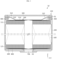
- FIG. 5 is a diagram showing the flow of gas and flame inside the battery 10 according to an embodiment of the present disclosure.
- the thermal conductive member 400 may include ceramic filler.
- the thermal conductive member 400 may include alumina and/or boron nitride and/or silicon nitride and/or aluminum nitride and/or aluminum hydroxide.
- the thermal conductive member may have a hardness of 70Sh A or higher. Through this material of the thermal conductive member 400, the rigidity of the structurally weak beading portion 210 can be strengthened.
- the thermal conductive member 400 may be a thermal conductive adhesive.
- the thermal conductive member 400 may be a short-cure adhesive.
- the thermal conductive adhesive may be configured to adhere the upper part of the beading portion 210 and the lower part of the beading portion 210.
- the beading portion 210 when gas is generated inside the battery 10 or a strong impact is applied to the battery 10 from the outside of the battery 10, the beading portion 210, which is vulnerable to deformation, may be prevented from being stretched in the vertical direction.
- the thermal conductive adhesive 400 is interposed between the upper part of the beading portion 210 and the lower part of the beading portion 210 to prevent the upper part of the beading portion 210 and the lower part of the beading portion 210 from moving away from each other.
- the battery 10 may include a crimping portion 220 of the battery housing 200 and/or a vent portion 310 and/or a terminal 700 of the top cap 300 and/or a first current collector 500 and/or a second current collector 600 and/or an insulator 800 and/or a first gasket G1 and/or a second gasket G2.
- the battery housing 200 may include a crimping portion 220.
- the crimping portion 220 may be formed on the upper portion of the beading portion 210.
- the crimping portion 220 may be extended and bent to surround the edge area of the top cap 300.
- the top cap 300 may be fixed on the beading portion 210 by the shape of the crimping portion 220.
- the terminal 700 may be located on the opposite side of the opening.
- the terminal 700 may be exposed to the outside of the battery housing 200 through a closed portion located on the opposite side of the opening.
- the terminal 700 may have the polarity of the second electrode.
- the terminal 700 may penetrate approximately the center of the lower surface of the battery housing 200.
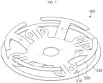
- the first current collector 500 may be located between the electrode assembly 100 and the top cap 300.
- the first current collector 500 may have a first coupling portion 510 that is electrically coupled to the electrode assembly 100.
- the first current collector 500 may be provided with a housing coupling portion 520 that is electrically coupled to the battery housing 200 on the inner surface of the battery housing 200.
- the first current collector 500 may have the polarity of the first electrode.
- the second current collector 600 may be located between the electrode assembly 100 and the terminal 700.
- the second current collector 600 may have a second coupling portion that is electrically coupled to the electrode assembly 100.
- the second current collector 600 may be provided with a terminal 700 coupling portion that is electrically coupled to a portion where the terminal 700 is inserted into the battery housing 200 and has a substantially flat surface.
- the second current collector 600 may have the polarity of the second electrode.
- the second gasket G2 may be provided between the terminal 700 and the battery housing 200.
- the second gasket G2 prevents the terminal 700 and the battery housing 200 from contacting each other.
- the first gasket G1 and the second gasket G2 may be made of a resin material with insulating properties and elasticity.
- the first current collector 500 may include a beading portion protecting portion 530.
- the beading portion protecting portion 530 may be provided between the beading portion 210 and the electrode assembly 100.
- the beading portion protecting portion 530 may extend along the circumferential direction of the battery 10.
- the beading portion protecting portion 530 may be formed integrally with the first coupling portion 510.
- the beading portion protecting portion 530 may be thicker than the first coupling portion 510.
- the first coupling portion 510 may extend from approximately the center to the inner surface of the battery housing 200 and be connected to the beading portion coupling portion 530.
- the first electrode 110, the first current collector 500, and the battery housing 200 have the same polarity, so there is no problem even if they are electrically connected.
- the beading portion protecting portion 530 is not a component of the first current collector 500, but is a separate component and may be configured to contact the first coupling portion 510.
- FIG. 8 is a diagram showing a battery pack 5 according to the present disclosure.
- the battery pack 5 may include the battery 10.
- the battery pack 5 may further include various components other than the battery 10, such as BMS, busbar, pack case, relay, current sensor, etc. known at the time of filing the present disclosure..
- the vehicle 3 according to the present disclosure may include the battery pack 5.
- the vehicle 3 may be a hybrid vehicle 3 or an electric vehicle 3.
- the vehicle 3 according to the present disclosure further includes various other components included in the vehicle 3 in addition to the battery pack 5.
- the vehicle 3 according to the present disclosure may further include a vehicle body, a motor, and control devices such as an ECU (electronic control unit) in addition to the battery pack 5 according to the present disclosure.
- ECU electronic control unit
Landscapes
- Chemical & Material Sciences (AREA)
- Chemical Kinetics & Catalysis (AREA)
- Electrochemistry (AREA)
- General Chemical & Material Sciences (AREA)
- Engineering & Computer Science (AREA)
- Manufacturing & Machinery (AREA)
- Aviation & Aerospace Engineering (AREA)
- Sealing Battery Cases Or Jackets (AREA)
- Secondary Cells (AREA)
- Connection Of Batteries Or Terminals (AREA)
- Battery Mounting, Suspending (AREA)
- Gas Exhaust Devices For Batteries (AREA)
- Cell Separators (AREA)
Applications Claiming Priority (2)
| Application Number | Priority Date | Filing Date | Title |
|---|---|---|---|
| KR20220089218 | 2022-07-19 | ||
| PCT/KR2023/010445 WO2024019547A1 (ko) | 2022-07-19 | 2023-07-19 | 배터리, 이를 포함하는 배터리 팩과 자동차 |
Publications (2)
| Publication Number | Publication Date |
|---|---|
| EP4539232A1 true EP4539232A1 (de) | 2025-04-16 |
| EP4539232A4 EP4539232A4 (de) | 2026-03-18 |
Family
ID=89618266
Family Applications (1)
| Application Number | Title | Priority Date | Filing Date |
|---|---|---|---|
| EP23843393.2A Pending EP4539232A4 (de) | 2022-07-19 | 2023-07-19 | Batterie und batteriepack sowie fahrzeug damit |
Country Status (6)
| Country | Link |
|---|---|
| EP (1) | EP4539232A4 (de) |
| JP (1) | JP2025523374A (de) |
| KR (1) | KR20240011644A (de) |
| CN (1) | CN118975031A (de) |
| CA (1) | CA3261207A1 (de) |
| WO (1) | WO2024019547A1 (de) |
Families Citing this family (2)
| Publication number | Priority date | Publication date | Assignee | Title |
|---|---|---|---|---|
| WO2026034904A1 (ko) * | 2024-08-06 | 2026-02-12 | 주식회사 엘지에너지솔루션 | 배터리 팩의 절연 구조와 이를 포함하는 배터리 팩 및 운송 수단 |
| WO2026038821A1 (ko) * | 2024-08-16 | 2026-02-19 | 주식회사 엘지에너지솔루션 | 배터리 셀, 배터리 팩 및 이를 포함하는 자동차 |
Family Cites Families (14)
| Publication number | Priority date | Publication date | Assignee | Title |
|---|---|---|---|---|
| JPS5560663U (de) * | 1978-10-20 | 1980-04-24 | ||
| JPS60124858U (ja) * | 1984-01-31 | 1985-08-22 | 新神戸電機株式会社 | 密閉形アルカリ蓄電池 |
| JPH0729572Y2 (ja) * | 1989-05-24 | 1995-07-05 | 富士電気化学株式会社 | 筒形電池 |
| JP2002231194A (ja) * | 2001-01-31 | 2002-08-16 | Sanyo Electric Co Ltd | 密閉型電池 |
| KR100646504B1 (ko) * | 2004-12-01 | 2006-11-15 | 삼성에스디아이 주식회사 | 원통형 리튬 이차 전지 |
| KR100973423B1 (ko) * | 2006-10-16 | 2010-08-02 | 주식회사 엘지화학 | 안전성이 향상된 원통형 전지 |
| TW200906250A (en) * | 2007-07-27 | 2009-02-01 | Samsung Electro Mech | Mask for screen printing and screen printing method using the same |
| KR100941984B1 (ko) * | 2007-09-28 | 2010-02-11 | 삼성전기주식회사 | 웨이퍼를 패키징하는 방법 |
| KR101483703B1 (ko) * | 2012-07-06 | 2015-01-16 | 주식회사 엘지화학 | 이차전지 및 그의 제조방법 |
| CN109148745B (zh) * | 2017-06-28 | 2020-06-19 | 比亚迪股份有限公司 | 电池盖板组件、单体电池、电池模组、动力电池包和电动汽车 |
| KR20220089218A (ko) | 2020-12-21 | 2022-06-28 | 엘지전자 주식회사 | 공기조화기 및 그 제어 방법 |
| CN219040512U (zh) * | 2021-07-06 | 2023-05-16 | 江苏时代新能源科技有限公司 | 电池单体、电池、用电设备及电池单体的制造设备 |
| CN216563457U (zh) * | 2021-12-29 | 2022-05-17 | 远景动力技术(江苏)有限公司 | 电池、电池包和电子设备 |
| CN114725628B (zh) * | 2022-04-21 | 2024-05-10 | 远景动力技术(江苏)有限公司 | 一种电池组件和电池制造方法 |
-
2023
- 2023-07-19 CA CA3261207A patent/CA3261207A1/en active Pending
- 2023-07-19 CN CN202380032344.8A patent/CN118975031A/zh active Pending
- 2023-07-19 WO PCT/KR2023/010445 patent/WO2024019547A1/ko not_active Ceased
- 2023-07-19 EP EP23843393.2A patent/EP4539232A4/de active Pending
- 2023-07-19 JP JP2024570550A patent/JP2025523374A/ja active Pending
- 2023-07-19 KR KR1020230094087A patent/KR20240011644A/ko active Pending
Also Published As
| Publication number | Publication date |
|---|---|
| JP2025523374A (ja) | 2025-07-23 |
| EP4539232A4 (de) | 2026-03-18 |
| CN118975031A (zh) | 2024-11-15 |
| CA3261207A1 (en) | 2025-06-13 |
| WO2024019547A1 (ko) | 2024-01-25 |
| KR20240011644A (ko) | 2024-01-26 |
Similar Documents
| Publication | Publication Date | Title |
|---|---|---|
| JP7618810B2 (ja) | 円筒形バッテリーセル、それを含むバッテリーパック及び自動車 | |
| US20240274982A1 (en) | Secondary battery, and battery pack and vehicle comprising same | |
| EP4191760B1 (de) | Sekundärbatterie | |
| EP4539232A1 (de) | Batterie und batteriepack sowie fahrzeug damit | |
| KR20220092100A (ko) | 이차전지 및 이의 제조 방법 | |
| EP4195400A1 (de) | Sekundärbatterie | |
| EP4572000A1 (de) | Batterie und batteriepack sowie fahrzeug damit | |
| US20250210812A1 (en) | Battery, and battery pack and vehicle including the same | |
| CN119096403A (zh) | 电池电芯、电池组以及包括该电池组的车辆 | |
| EP4571964A1 (de) | Batterie und batteriepack und fahrzeug mit der batterie | |
| KR20240162376A (ko) | 원통형 배터리, 그리고 이를 포함하는 배터리 팩 및 자동차 | |
| US12362396B2 (en) | Secondary battery | |
| EP4513664A1 (de) | Batterie und batteriepack und fahrzeug mit der batterie | |
| KR20250028129A (ko) | 배터리 및 이에 적용되는 인슐레이터, 그리고 이를 포함하는 배터리 팩 및 자동차 | |
| CN120693730A (zh) | 电池以及包括该电池的电池组和车辆 | |
| KR20250101458A (ko) | 전극 조립체, 그리고 이를 포함하는 배터리 및 배터리 팩 | |
| CN117616627A (zh) | 二次电池和包括该二次电池的电池模块 |
Legal Events
| Date | Code | Title | Description |
|---|---|---|---|
| STAA | Information on the status of an ep patent application or granted ep patent |
Free format text: STATUS: THE INTERNATIONAL PUBLICATION HAS BEEN MADE |
|
| PUAI | Public reference made under article 153(3) epc to a published international application that has entered the european phase |
Free format text: ORIGINAL CODE: 0009012 |
|
| STAA | Information on the status of an ep patent application or granted ep patent |
Free format text: STATUS: REQUEST FOR EXAMINATION WAS MADE |
|
| 17P | Request for examination filed |
Effective date: 20250113 |
|
| AK | Designated contracting states |
Kind code of ref document: A1 Designated state(s): AL AT BE BG CH CY CZ DE DK EE ES FI FR GB GR HR HU IE IS IT LI LT LU LV MC ME MK MT NL NO PL PT RO RS SE SI SK SM TR |
|
| DAV | Request for validation of the european patent (deleted) | ||
| DAX | Request for extension of the european patent (deleted) | ||
| RIC1 | Information provided on ipc code assigned before grant |
Ipc: H01M 50/367 20210101AFI20250916BHEP Ipc: H01M 50/171 20210101ALI20250916BHEP Ipc: H01M 50/107 20210101ALI20250916BHEP Ipc: H01M 50/167 20210101ALI20250916BHEP Ipc: H01M 10/653 20140101ALI20250916BHEP |
|
| A4 | Supplementary search report drawn up and despatched |
Effective date: 20260213 |
|
| RIC1 | Information provided on ipc code assigned before grant |
Ipc: H01M 50/367 20210101AFI20260209BHEP Ipc: H01M 50/171 20210101ALI20260209BHEP Ipc: H01M 50/107 20210101ALI20260209BHEP Ipc: H01M 50/167 20210101ALI20260209BHEP Ipc: H01M 10/653 20140101ALI20260209BHEP |