EP4538984A2 - Analyse von multielektrodenkathetersignalen zur bestimmung eines elektrophysiologischen (ep) wellenausbreitungsvektors - Google Patents
Analyse von multielektrodenkathetersignalen zur bestimmung eines elektrophysiologischen (ep) wellenausbreitungsvektors Download PDFInfo
- Publication number
- EP4538984A2 EP4538984A2 EP25152612.5A EP25152612A EP4538984A2 EP 4538984 A2 EP4538984 A2 EP 4538984A2 EP 25152612 A EP25152612 A EP 25152612A EP 4538984 A2 EP4538984 A2 EP 4538984A2
- Authority
- EP
- European Patent Office
- Prior art keywords
- section
- processor
- tissue
- locations
- lat
- Prior art date
- Legal status (The legal status is an assumption and is not a legal conclusion. Google has not performed a legal analysis and makes no representation as to the accuracy of the status listed.)
- Pending
Links
Images


Classifications
-
- A—HUMAN NECESSITIES
- A61—MEDICAL OR VETERINARY SCIENCE; HYGIENE
- A61B—DIAGNOSIS; SURGERY; IDENTIFICATION
- A61B5/00—Measuring for diagnostic purposes; Identification of persons
- A61B5/24—Detecting, measuring or recording bioelectric or biomagnetic signals of the body or parts thereof
- A61B5/25—Bioelectric electrodes therefor
- A61B5/279—Bioelectric electrodes therefor specially adapted for particular uses
- A61B5/28—Bioelectric electrodes therefor specially adapted for particular uses for electrocardiography [ECG]
- A61B5/283—Invasive
- A61B5/287—Holders for multiple electrodes, e.g. electrode catheters for electrophysiological study [EPS]
-
- A—HUMAN NECESSITIES
- A61—MEDICAL OR VETERINARY SCIENCE; HYGIENE
- A61B—DIAGNOSIS; SURGERY; IDENTIFICATION
- A61B5/00—Measuring for diagnostic purposes; Identification of persons
- A61B5/24—Detecting, measuring or recording bioelectric or biomagnetic signals of the body or parts thereof
- A61B5/316—Modalities, i.e. specific diagnostic methods
- A61B5/318—Heart-related electrical modalities, e.g. electrocardiography [ECG]
- A61B5/339—Displays specially adapted therefor
- A61B5/341—Vectorcardiography [VCG]
-
- A—HUMAN NECESSITIES
- A61—MEDICAL OR VETERINARY SCIENCE; HYGIENE
- A61B—DIAGNOSIS; SURGERY; IDENTIFICATION
- A61B5/00—Measuring for diagnostic purposes; Identification of persons
- A61B5/24—Detecting, measuring or recording bioelectric or biomagnetic signals of the body or parts thereof
- A61B5/316—Modalities, i.e. specific diagnostic methods
- A61B5/318—Heart-related electrical modalities, e.g. electrocardiography [ECG]
- A61B5/339—Displays specially adapted therefor
- A61B5/343—Potential distribution indication
-
- A—HUMAN NECESSITIES
- A61—MEDICAL OR VETERINARY SCIENCE; HYGIENE
- A61B—DIAGNOSIS; SURGERY; IDENTIFICATION
- A61B5/00—Measuring for diagnostic purposes; Identification of persons
- A61B5/72—Signal processing specially adapted for physiological signals or for diagnostic purposes
- A61B5/7271—Specific aspects of physiological measurement analysis
- A61B5/7278—Artificial waveform generation or derivation, e.g. synthesizing signals from measured signals
-
- A—HUMAN NECESSITIES
- A61—MEDICAL OR VETERINARY SCIENCE; HYGIENE
- A61B—DIAGNOSIS; SURGERY; IDENTIFICATION
- A61B5/00—Measuring for diagnostic purposes; Identification of persons
- A61B5/74—Details of notification to user or communication with user or patient; User input means
- A61B5/742—Details of notification to user or communication with user or patient; User input means using visual displays
- A61B5/743—Displaying an image simultaneously with additional graphical information, e.g. symbols, charts, function plots
-
- A—HUMAN NECESSITIES
- A61—MEDICAL OR VETERINARY SCIENCE; HYGIENE
- A61B—DIAGNOSIS; SURGERY; IDENTIFICATION
- A61B5/00—Measuring for diagnostic purposes; Identification of persons
- A61B5/68—Arrangements of detecting, measuring or recording means, e.g. sensors, in relation to patient
- A61B5/6846—Arrangements of detecting, measuring or recording means, e.g. sensors, in relation to patient specially adapted to be brought in contact with an internal body part, i.e. invasive
- A61B5/6847—Arrangements of detecting, measuring or recording means, e.g. sensors, in relation to patient specially adapted to be brought in contact with an internal body part, i.e. invasive mounted on an invasive device
- A61B5/6852—Catheters
- A61B5/6858—Catheters with a distal basket, e.g. expandable basket
-
- A—HUMAN NECESSITIES
- A61—MEDICAL OR VETERINARY SCIENCE; HYGIENE
- A61B—DIAGNOSIS; SURGERY; IDENTIFICATION
- A61B5/00—Measuring for diagnostic purposes; Identification of persons
- A61B5/68—Arrangements of detecting, measuring or recording means, e.g. sensors, in relation to patient
- A61B5/6846—Arrangements of detecting, measuring or recording means, e.g. sensors, in relation to patient specially adapted to be brought in contact with an internal body part, i.e. invasive
- A61B5/6847—Arrangements of detecting, measuring or recording means, e.g. sensors, in relation to patient specially adapted to be brought in contact with an internal body part, i.e. invasive mounted on an invasive device
- A61B5/6852—Catheters
- A61B5/6859—Catheters with multiple distal splines
Definitions
- the present invention relates generally to electrophysiological mapping, and particularly to cardiac electrophysiological mapping.
- U.S. Patent Application Publication 2017/0311833 describes an efficient system for diagnosing arrhythmias and directing catheter therapies that may allow for measuring, classifying, analyzing, and mapping spatial EP patterns within a body.
- the efficient system may further guide arrhythmia therapy and update maps as treatment is delivered.
- the efficient system may use a medical device having a high density of sensors with a known spatial configuration for collecting EP data and positioning data.
- the efficient system may also use an electronic control system for computing and providing the user with a variety of metrics, derivative metrics, high definition (HD) maps, HD composite maps, and general visual aids for association with a geometrical anatomical model shown on a display device.
- U.S. Patent Application Publication 2018/0153426 describes method and system for mapping an anatomical structure, that include sensing activation signals of intrinsic physiological activity with a plurality of mapping electrodes disposed in or near the anatomical structure, each of the plurality of mapping electrodes having an electrode location.
- a vector field map which represents a direction of propagation of the activation signals at each electrode location is generated to identify a signature pattern and a location in the vector field map according to at least one vector field template.
- a target location of the identified signature pattern is identified according to a corresponding electrode location.
- An embodiment of the present invention provides a method including receiving (i) multiple electrophysiological (EP) signals acquired by multiple electrodes of a multi-electrode catheter that are in contact with tissue in a region of a cardiac chamber, and (ii) respective tissue locations at which the electrodes acquired the EP signals.
- the region is divided into two sections.
- local activation times (LAT) are calculated for the respective tissue locations, and found are: a first section of the two sections having a smaller average LAT value, and a second section of the two sections having a higher average value.
- Determined are a first representative location in the first section, and a second representative location in the second section.
- a propagation vector is calculated between the first and second representative locations, that is indicative of propagation of an EP wave that has generated the EP signals.
- the propagation vector is presented to a user.
- the graphical property of the arrow includes one or more of a color, a length, a width, and a graphical pattern such as a gradient or dashes.
- determining the first representative location includes determining a tissue location having a smallest LAT value among the tissue locations in the first section, and wherein determining the second representative location includes determining a tissue location having a largest LAT value among the tissue locations in the second section.
- determining the first representative location includes calculating a first center-of-mass of the tissue locations in the first section, and wherein determining the second representative location includes calculating a second center-of-mass of the tissue locations in the second section.
- a system including an interface and a processor.
- the interface is configured to receive (i) multiple electrophysiological (EP) signals acquired by multiple electrodes of a multi-electrode catheter that are in contact with tissue in a region of a cardiac chamber, and (ii) respective tissue locations at which the electrodes acquired the EP signals.
- EP electrophysiological
- the processor is configured to (a) divide the region into two sections, (b) using the EP signals acquired by the electrodes, calculate local activation time (LAT) values for the respective tissue locations, and find a first section of the two sections having a smaller average LAT value, and a second section of the two sections having a higher average value, (c) determine a first representative location in the first section, and a second representative location in the second section, (d) calculate between the first and second representative locations a propagation vector indicative of propagation of an EP wave that has generated the EP signals, and (e) present the propagation vector to a user.
- LAT local activation time
- Intracardiac electrophysiological (EP) mapping is a catheter-based method that is sometimes applied to characterize cardiac EP wave propagation abnormalities, such those that cause an arrhythmia.
- a distal end of a catheter which comprises multiple sensing-electrodes, is inserted into the heart to sense a set of data points comprising measured locations over a wall tissue of a cardiac chamber and a respective set of EP signals, from which the EP mapping system can produce a map, such as an EP map, of the cardiac chamber.
- the propagation direction of the EP wave at a region of the wall tissue may also be needed.
- the propagation direction of the cardiac wave can be found by creating a particular EP timing diagram map, called local activation time (LAT) map, of regions of the cardiac chamber.
- LAT local activation time
- a processor to calculate a propagation vector, first divides (e.g., arbitrarily divides) the cardiac tissue region where the electrode locations are into two sections, using a virtual plane containing the axis of the catheter. Then, using EP signals acquired from each electrode, the processor calculates the LAT values at the electrode locations (i.e., respective tissue locations) in each section to find a first section of the two sections having the smaller average LAT values, and a second section of the two sections having higher average value.
- the processor finds the location with the minimum LAT value therein.
- the processor finds the location with the maximum LAT value therein. From the known displacements (distance and direction) between the two locations, and the respective known time difference in LAT values, the processor calculates a propagation (e.g., velocity) vector (speed and direction) of the EP wave. The processor may then draw an arrow, corresponding to the vector, on a map of the cardiac chamber. The length of the arrow, its color or a graphical pattern (e.g., gradient or hatched patterns) may be set to correspond to the speed.
- the processor calculates a vector between a center-of-mass wall tissue location of the lower average LAT value and a center-of-mass wall tissue location of the higher average LAT value. To this end, the processor performs a center-of-mass calculation in the first section of a first wall tissue location of the lower average LAT value and a center-of-mass calculation in the second section of a second wall tissue location of the higher average LAT value.
- the processor calculates a center-of-mass propagation vector between the first and second center-of-mass locations of an EP wave that presumably generated the EP signals, and presents the center-of-mass propagation vector to a user.
- the center-of-mass calculations typically include calculating a weighted average of each center-of-mass location using two or more LAT values of each section as weights.
- the velocity vector oscillates in direction (backwards and forwards). This occurs typically if the catheter is at a junction, where the wave actually alternates in direction, for example, due to the wave encountering aberrant unidirectional propagation-blocking tissue.
- the processor calculates an additional vector, and the two vectors may be displayed on the screen as two arrows distinguished by a different brightness/thickness/length/color according to their relative magnitude.
- the processor is programmed in software containing a particular algorithm that enables the processor to conduct each of the processor-related steps and functions outlined above.
- the disclosed systems and methods for efficient derivation and clear presentation of propagation direction(s) of an EP wave may improve catheter-based arrhythmia diagnostics and treatment procedures.
- Fig. 1 is a schematic, pictorial illustration of an electrophysiological (EP) mapping system 10 comprising different possible multi-electrode catheters, in accordance with embodiments of the present invention.
- System 10 may be configured to analyze substantially any physiological parameter or combinations of such parameters.
- the analyzed signals are assumed to be intra-cardiac electrogram potential-time relationships.
- the signals at various locations need to be referenced in time to each other, such as is done during LAT map generation.
- the time referencing is accomplished by measuring relative to a reference time (e.g., an instance in time), such as the beginning of each QRS complex of an ECG reference signal (i.e., the beginning of every heartbeat).
- a reference time e.g., an instance in time
- the method for generating an LAT map is described in U.S Patent 9,050,011 , cited above.
- Multi-electrode catheter 14/114 is inserted by a physician 32 through the patient's vascular system into a chamber or vascular structure of a heart 12.
- Physician 32 brings the catheter's distal tip 18/118 into contact with (e.g., presses the tip distally against) wall tissue 19 of a cardiac chamber 21, at an EP mapping target tissue site.
- the catheter typically comprises a handle 20 which has suitable controls to enable physician 32 to steer, position and orient the distal end of the catheter as desired for EP mapping.
- the multi-electrode catheter 14/114 is coupled to a console 24, which enables physician 32 to observe and regulate the functions of the catheter.
- the distal portion of the catheter may contain various sensors, such as contact force sensors (not shown) and a magnetic sensor 33/133 that provides position, direction, and orientation signals to a processor 22, located in a console 24.
- Processor 22 may fulfill several processing functions as described below.
- electrical signals can be conveyed to and from heart 12 from electrodes 16/116 located at or near the distal tip 18 of catheter 14/114 via cable 34 to console 24.
- Pacing signals and other control signals may be conveyed from console 24 through cable 34 and electrodes 16/116 to heart 12.
- Console 24 includes a monitor 29 driven by processor 22.
- Signal processing circuits in an electrical interface 34 typically receive, amplify, filter, and digitize signals from catheter 14/114, including signals generated by the above-noted sensors and the plurality of sensing electrodes 16. The digitized signals are received and used by console 24 and the positioning system to compute the position and orientation of catheter 14/114 and to analyze the EP signals from electrodes 16/116 as described in further detail below.
- the respective locations of electrodes 16/116 are tracked.
- the tracking may be performed, for example, using the CARTO ® 3 system, produced by Biosense-Webster.
- Such a system measures impedances between electrodes 16/116 and a plurality of external electrodes 30 that are coupled to the body of the patient.
- three external electrodes 30 may be coupled to the patient's chest, and another three external electrodes may be coupled to the patient's back. (For ease of illustration, only chest electrodes are shown in Fig. 1 .).
- Wire connections 35 link the console 24 with body surface electrodes 30 and other components of a positioning subsystem to measure location and orientation coordinates of catheter 14/114.
- electrical activation maps may be prepared, according to the methods disclosed in U.S. Patents 6,226,542 , and 6,301,496 , and 6,892,091 , which are assigned to the assignee of the present patent application and whose disclosure is incorporated herein by reference with a copy provided in the Appendix.
- Processor 22 uses software stored in a memory 25 to operate system 10.
- the software may be downloaded to processor 22 in electronic form, over a network, for example, or it may, alternatively or additionally, be provided and/or stored on non-transitory tangible media, such as magnetic, optical, or electronic memory.
- processor 22 runs a dedicated algorithm as disclosed herein, including in Fig. 4 , that enables processor 22 to perform the disclosed steps, as further described below.
- Fig. 1 The example illustration shown in Fig. 1 is chosen purely for the sake of conceptual clarity.
- Other types of EP sensing geometries such as of a balloon catheter comprising electrode segments, described in U.S Patent application 16/708285 (Attorney Docket No. BIO6163USNP), titled, "Catheter with Plurality of Sensing Electrodes Used as Ablation Electrodes,” filed December 9, 2019 , whose disclosure is incorporated herein by reference (with a copy in the Appendix), may also be employed.
- System 20 typically comprises additional modules and elements that are not directly related to the disclosed techniques, and thus are intentionally omitted from Fig. 1 and from the corresponding description.
- the elements of system 20 and the methods described herein may be further applied, for example, to control an ablation of tissue of heart 12.
- Figs. 2A and 2B are schematic distal views of electrodes 16/116 of one of the catheters of Fig. 1 in contact with tissue and measuring electrophysiological (EP) signals, in accordance with embodiments of the present invention.
- the figures further show tissue 50 and a distal portion 40 of the spines or arms 15/115 of catheter 14/114 that are pressed against tissue 50, as viewed at a distal direction from a location proximally to the spines or arms on the axis L-L of the catheter.
- the spines or arms 15/115 are coupled together at distal tip 18/118 of the catheter.
- virtual plane 55 separates the spines or arms into two sections, a first section S1 with the lower average LAT value and another or second section S2 with a higher average LAT value.
- the first section S1 is determined by the processor to find the minimum LAT value, and its location is determined to be at point 60 (which may be the location of a sensing electrode on the spine or arm of a catheter 14 or 114).
- the processor finds the maximum LAT value, and its location 66 (which may be the location of a sensing electrode on the spine or arm of a catheter 14 or 114).
- Locations 60 and 66 are referred to herein as "representative locations" because each of them represents its entire respective section by a single data point.
- the processor calculates a velocity vector (speed and direction) of an EP wave 100 that generated the signals as it propagates in tissue under the catheter.
- the processor may then draw an arrow 65, corresponding to the vector, on a map of the cardiac chamber and provide this in display screen 29.
- the length of arrow 65, and/or its color, may be set to correspond to the speed.
- center-of-mass wall tissue location 70 is calculated from Eq. 1 using LAT values and respective locations 68 and 72
- center-of-mass wall tissue location 80 is calculated using LAT values and respective locations 78 and 82.
- the processor may then draw an arrow 75 corresponding to the vector between locations 70 and 80.
- the centers-of-mass of the two sections serve as the representative locations.
- processor 22 may choose the representative locations in the two sections in any other suitable way.
- the velocity vector at the region may oscillate in direction (backwards and forwards). This occurs typically if the catheter is at a junction where EP wave 100 is actually alternating in direction, for example, due to the wave encountering an aberrant unidirectional propagation blocking tissue 52.
- the two EP wave vectors (one of incident EP wave 100 and the other of reentry EP wave 102) may be displayed on the screen as two respective arrows, 95 and 97, each with a different brightness/thickness/length/color according to their relative magnitudes.
- the vectors are calculated using the center-of-mass calculation method of Fig. 2B .
- One respective vector points from center-of-mass location 90 to center-of-mass location 99, and the other from center-of-mass location 91 to center-of-mass location 97.
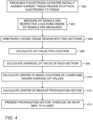
- system 10 measures electrode locations over wall tissue 19 of cardiac chamber 21 and a respective set of EP signals at the locations, generated by an EP wave 100, at a measurement step 402.
- processor 22 arbitrarily divides the region into two sections, at a region division step 404.
- processor 22 calculates an LAT value at each electrode location, at an LAT calculation step 406.
- processor 22 calculates center-of-mass locations of the lower and higher average LAT values, using the method described in Fig. 2B .
- processor 22 overlays (e.g., draws) an arrow, corresponding to the vector, on a map of the cardiac chamber as shown on display 29 in Fig. 1 .
- the length of the arrow 65 or 75, and/or its color, may be set to correspond to the speed.
- the example flow chart shown in Fig. 4 is chosen purely for the sake of conceptual clarity.
- the present embodiment also comprises additional steps of the algorithm, such as operating other sensors mounted on the catheter, such as contact force sensors, which have been omitted from the disclosure herein purposely on order to provide a more simplified flow chart.
Landscapes
- Health & Medical Sciences (AREA)
- Life Sciences & Earth Sciences (AREA)
- Engineering & Computer Science (AREA)
- Animal Behavior & Ethology (AREA)
- Public Health (AREA)
- Pathology (AREA)
- Physics & Mathematics (AREA)
- Biomedical Technology (AREA)
- Heart & Thoracic Surgery (AREA)
- Medical Informatics (AREA)
- Molecular Biology (AREA)
- Surgery (AREA)
- Veterinary Medicine (AREA)
- General Health & Medical Sciences (AREA)
- Biophysics (AREA)
- Cardiology (AREA)
- Physiology (AREA)
- Nuclear Medicine, Radiotherapy & Molecular Imaging (AREA)
- Radiology & Medical Imaging (AREA)
- Artificial Intelligence (AREA)
- Computer Vision & Pattern Recognition (AREA)
- Psychiatry (AREA)
- Signal Processing (AREA)
- Measurement And Recording Of Electrical Phenomena And Electrical Characteristics Of The Living Body (AREA)
Applications Claiming Priority (2)
| Application Number | Priority Date | Filing Date | Title |
|---|---|---|---|
| US16/918,972 US11730413B2 (en) | 2020-07-01 | 2020-07-01 | Analyzing multi-electrode catheter signals to determine electrophysiological (EP) wave propagation vector |
| EP21182626.8A EP3932313B1 (de) | 2020-07-01 | 2021-06-30 | Analyse von mehreren elektrodenkathetersignalen zur bestimmung des elektrophysiologischen (ep) wellenausbreitungsvektors |
Related Parent Applications (1)
| Application Number | Title | Priority Date | Filing Date |
|---|---|---|---|
| EP21182626.8A Division EP3932313B1 (de) | 2020-07-01 | 2021-06-30 | Analyse von mehreren elektrodenkathetersignalen zur bestimmung des elektrophysiologischen (ep) wellenausbreitungsvektors |
Publications (2)
| Publication Number | Publication Date |
|---|---|
| EP4538984A2 true EP4538984A2 (de) | 2025-04-16 |
| EP4538984A3 EP4538984A3 (de) | 2025-05-14 |
Family
ID=76730288
Family Applications (2)
| Application Number | Title | Priority Date | Filing Date |
|---|---|---|---|
| EP21182626.8A Active EP3932313B1 (de) | 2020-07-01 | 2021-06-30 | Analyse von mehreren elektrodenkathetersignalen zur bestimmung des elektrophysiologischen (ep) wellenausbreitungsvektors |
| EP25152612.5A Pending EP4538984A3 (de) | 2020-07-01 | 2021-06-30 | Analyse von multielektrodenkathetersignalen zur bestimmung eines elektrophysiologischen (ep) wellenausbreitungsvektors |
Family Applications Before (1)
| Application Number | Title | Priority Date | Filing Date |
|---|---|---|---|
| EP21182626.8A Active EP3932313B1 (de) | 2020-07-01 | 2021-06-30 | Analyse von mehreren elektrodenkathetersignalen zur bestimmung des elektrophysiologischen (ep) wellenausbreitungsvektors |
Country Status (5)
| Country | Link |
|---|---|
| US (2) | US11730413B2 (de) |
| EP (2) | EP3932313B1 (de) |
| JP (1) | JP7802469B2 (de) |
| CN (1) | CN113876330B (de) |
| IL (1) | IL284246B2 (de) |
Citations (10)
| Publication number | Priority date | Publication date | Assignee | Title |
|---|---|---|---|---|
| US6226542B1 (en) | 1998-07-24 | 2001-05-01 | Biosense, Inc. | Three-dimensional reconstruction of intrabody organs |
| US6301496B1 (en) | 1998-07-24 | 2001-10-09 | Biosense, Inc. | Vector mapping of three-dimensionally reconstructed intrabody organs and method of display |
| US6892091B1 (en) | 2000-02-18 | 2005-05-10 | Biosense, Inc. | Catheter, method and apparatus for generating an electrical map of a chamber of the heart |
| US7536218B2 (en) | 2005-07-15 | 2009-05-19 | Biosense Webster, Inc. | Hybrid magnetic-based and impedance-based position sensing |
| US7756576B2 (en) | 2005-08-26 | 2010-07-13 | Biosense Webster, Inc. | Position sensing and detection of skin impedance |
| US8456182B2 (en) | 2008-09-30 | 2013-06-04 | Biosense Webster, Inc. | Current localization tracker |
| US9050011B2 (en) | 2012-12-26 | 2015-06-09 | Biosense Webster (Israel) Ltd. | Removal of artifacts from map data |
| US20170042449A1 (en) | 2014-02-25 | 2017-02-16 | St. Jude Medical, Cardiology Division, Inc. | System and method for local electrophysiological characterization of cardiac substrate using multi-electrode catheters |
| US20170311833A1 (en) | 2010-12-30 | 2017-11-02 | St. Jude Medical, Atrial Fibrillation Division, Inc. | System and method for diagnosing arrhythmias and directing catheter therapies |
| US20180153426A1 (en) | 2013-05-14 | 2018-06-07 | Boston Scientific Scimed Inc. | Representation and identification of activity patterns during electro-physiology mapping using vector fields |
Family Cites Families (34)
| Publication number | Priority date | Publication date | Assignee | Title |
|---|---|---|---|---|
| US6236883B1 (en) | 1999-02-03 | 2001-05-22 | The Trustees Of Columbia University In The City Of New York | Methods and systems for localizing reentrant circuits from electrogram features |
| US6847839B2 (en) | 2001-07-30 | 2005-01-25 | The Trustees Of Columbia University In The City Of New York | System and method for determining reentrant ventricular tachycardia isthmus location and shape for catheter ablation |
| JP5632539B2 (ja) * | 2010-09-17 | 2014-11-26 | カーディオインサイト テクノロジーズ インコーポレイテッド | 興奮伝播図を計算するためのシステムおよび方法 |
| US9078573B2 (en) * | 2010-11-03 | 2015-07-14 | Cardioinsight Technologies, Inc. | System and methods for assessing heart function |
| US8620417B2 (en) * | 2011-09-22 | 2013-12-31 | Biosense Webster (Israel), Ltd. | Graphic user interface for physical parameter mapping |
| EP2994040B1 (de) * | 2013-05-07 | 2019-08-21 | Boston Scientific Scimed Inc. | System zur identifikation der ausbreitung von rotorvektoren |
| US9649046B2 (en) * | 2014-08-12 | 2017-05-16 | Biosense Webster (Israel) Ltd | Line of block detection |
| US9314179B1 (en) * | 2014-09-25 | 2016-04-19 | Apn Health, Llc | Time transformation of local activation times |
| US9474491B2 (en) * | 2014-10-15 | 2016-10-25 | St. Jude Medical, Cardiology Division, Inc. | Methods and systems for mapping local conduction velocity |
| WO2017040581A1 (en) | 2015-09-02 | 2017-03-09 | St. Jude Medical, Cardiology Division, Inc. | Methods and systems for identifying and mapping cardiac activation wavefronts |
| US10517496B2 (en) * | 2016-01-14 | 2019-12-31 | Biosense Webster (Israel) Ltd. | Region of interest focal source detection |
| US10582894B2 (en) * | 2016-01-14 | 2020-03-10 | Biosense Webster (Israel) Ltd. | Region of interest rotational activity pattern detection |
| US11219769B2 (en) * | 2016-02-26 | 2022-01-11 | Medtronic, Inc. | Noninvasive methods and systems of determining the extent of tissue capture from cardiac pacing |
| US10357168B2 (en) * | 2016-03-07 | 2019-07-23 | Apn Health, Llc | Time transformation of local activation times |
| US10136828B2 (en) * | 2016-03-31 | 2018-11-27 | Biosense Webster (Israel) Ltd. | Mapping of atrial fibrillation |
| JP6700421B2 (ja) | 2016-05-18 | 2020-05-27 | トペラ インコーポレイテッド | 生体リズム障害に関連付けられた遠隔ソースを識別するためのシステム及び方法 |
| CN110267586B (zh) * | 2017-02-10 | 2022-04-12 | 圣犹达医疗用品心脏病学部门有限公司 | 用于确定心脏现象的患病率的方法和系统 |
| US11284826B2 (en) * | 2017-09-06 | 2022-03-29 | Queen's University At Kingston | Methods for identifying wave break during atrial fibrillation |
| US10441188B2 (en) | 2017-09-12 | 2019-10-15 | Biosense Webster (Israel) Ltd. | Automatic display of earliest LAT point |
| WO2019156755A1 (en) | 2018-02-12 | 2019-08-15 | St. Jude Medical, Cardiology Division, Inc. | System and method for mapping cardiac muscle fiber orientation |
| US10665338B2 (en) | 2018-02-22 | 2020-05-26 | Biosense Webster (Israel) Ltd. | Automatic identification of multiple activation pathways |
| US11350867B2 (en) * | 2018-04-27 | 2022-06-07 | Duke University | Small-scale time delay and single-shot conduction velocity analysis and mapping for cardiac electrophysiology |
| EP3788588A4 (de) | 2018-04-30 | 2022-01-26 | The Board Of Trustees Of The Leland Stanford Junior University | System und verfahren zur erhaltung der gesundheit mittels persönlicher digitaler phänotypen |
| US11357437B2 (en) * | 2018-08-27 | 2022-06-14 | Biosense Webster (Israel) Ltd. | Automatic identification of abnormal LAT differences |
| US10786166B2 (en) | 2018-10-15 | 2020-09-29 | Biosense Webster (Israel) Ltd. | Mapping of activation wavefronts |
| US10842400B2 (en) | 2018-11-08 | 2020-11-24 | Biosense Webster (Israel) Ltd. | Iterative coherent mapping of cardiac electrophysiological (EP) activation including scar effects |
| US11564614B2 (en) * | 2019-10-30 | 2023-01-31 | St. Jude Medical, Cardiology Division, Inc. | Systems and methods for identifying ablation locations using electrical parameter data |
| US12262999B2 (en) * | 2019-11-05 | 2025-04-01 | Biosense Webster (Israel) Ltd. | Using statistical characteristics of multiple grouped ECG signals to detect inconsistent signals |
| US11366991B2 (en) * | 2019-11-05 | 2022-06-21 | Biosense Webster (Israel) Ltd | Optimizing mapping of ECG signals retrospectively by detecting inconsistency |
| US10842572B1 (en) | 2019-11-25 | 2020-11-24 | Farapulse, Inc. | Methods, systems, and apparatuses for tracking ablation devices and generating lesion lines |
| US11931182B2 (en) | 2019-12-09 | 2024-03-19 | Biosense Webster (Israel) Ltd. | Catheter with plurality of sensing electrodes used as ablation electrode |
| US11497427B2 (en) * | 2020-03-12 | 2022-11-15 | Biosense Webster (Israel) Ltd. | Adjusting annotation points in real time |
| CN115605136B (zh) * | 2020-05-19 | 2024-11-01 | 圣犹达医疗用品心脏病学部门有限公司 | 用于标测电生理激活的系统和方法 |
| US11439339B1 (en) * | 2020-10-16 | 2022-09-13 | Neucures Inc. | Method and system for measuring cardiac tissue health based on DV/DTmin of a depolarization wave within a cardiac electrogram |
-
2020
- 2020-07-01 US US16/918,972 patent/US11730413B2/en active Active
-
2021
- 2021-06-20 IL IL284246A patent/IL284246B2/en unknown
- 2021-06-30 JP JP2021108540A patent/JP7802469B2/ja active Active
- 2021-06-30 EP EP21182626.8A patent/EP3932313B1/de active Active
- 2021-06-30 EP EP25152612.5A patent/EP4538984A3/de active Pending
- 2021-07-01 CN CN202110747722.3A patent/CN113876330B/zh active Active
-
2023
- 2023-07-31 US US18/362,158 patent/US12350057B2/en active Active
Patent Citations (10)
| Publication number | Priority date | Publication date | Assignee | Title |
|---|---|---|---|---|
| US6226542B1 (en) | 1998-07-24 | 2001-05-01 | Biosense, Inc. | Three-dimensional reconstruction of intrabody organs |
| US6301496B1 (en) | 1998-07-24 | 2001-10-09 | Biosense, Inc. | Vector mapping of three-dimensionally reconstructed intrabody organs and method of display |
| US6892091B1 (en) | 2000-02-18 | 2005-05-10 | Biosense, Inc. | Catheter, method and apparatus for generating an electrical map of a chamber of the heart |
| US7536218B2 (en) | 2005-07-15 | 2009-05-19 | Biosense Webster, Inc. | Hybrid magnetic-based and impedance-based position sensing |
| US7756576B2 (en) | 2005-08-26 | 2010-07-13 | Biosense Webster, Inc. | Position sensing and detection of skin impedance |
| US8456182B2 (en) | 2008-09-30 | 2013-06-04 | Biosense Webster, Inc. | Current localization tracker |
| US20170311833A1 (en) | 2010-12-30 | 2017-11-02 | St. Jude Medical, Atrial Fibrillation Division, Inc. | System and method for diagnosing arrhythmias and directing catheter therapies |
| US9050011B2 (en) | 2012-12-26 | 2015-06-09 | Biosense Webster (Israel) Ltd. | Removal of artifacts from map data |
| US20180153426A1 (en) | 2013-05-14 | 2018-06-07 | Boston Scientific Scimed Inc. | Representation and identification of activity patterns during electro-physiology mapping using vector fields |
| US20170042449A1 (en) | 2014-02-25 | 2017-02-16 | St. Jude Medical, Cardiology Division, Inc. | System and method for local electrophysiological characterization of cardiac substrate using multi-electrode catheters |
Also Published As
| Publication number | Publication date |
|---|---|
| US20240023869A1 (en) | 2024-01-25 |
| CN113876330A (zh) | 2022-01-04 |
| EP3932313A1 (de) | 2022-01-05 |
| EP4538984A3 (de) | 2025-05-14 |
| US20220000382A1 (en) | 2022-01-06 |
| IL284246A (en) | 2022-01-01 |
| CN113876330B (zh) | 2025-09-02 |
| JP2022013880A (ja) | 2022-01-18 |
| US12350057B2 (en) | 2025-07-08 |
| EP3932313C0 (de) | 2025-01-22 |
| IL284246B2 (en) | 2024-07-01 |
| US11730413B2 (en) | 2023-08-22 |
| EP3932313B1 (de) | 2025-01-22 |
| JP7802469B2 (ja) | 2026-01-20 |
| IL284246B1 (en) | 2024-03-01 |
Similar Documents
| Publication | Publication Date | Title |
|---|---|---|
| JP7789485B2 (ja) | 自動パターン取得 | |
| JP7686388B2 (ja) | 医療装置及びその作動方法 | |
| EP3808272B1 (de) | Automatische identifizierung eines standorts einer fokalen quelle bei vorhofflimmern (af) | |
| EP1962689B1 (de) | System zur visualisierung der morphologie des herzens während der elektrophysiologischen abbildung und behandlung | |
| JP2018140171A (ja) | 電極信号に従った電極画像の強調表示 | |
| EP3795075B1 (de) | Verwendung von ergänzungsinformationen zur verbesserung von lösungen inverser probleme | |
| EP3662825A1 (de) | Detektion der bewegung eines koronarsinus (ks)-katheters | |
| JP7772298B2 (ja) | 心臓マッピング中の拒絶フィルタのリアルタイム評価 | |
| US12350057B2 (en) | Analyzing multi-electrode catheter signals to determine electrophysiological (EP) wave propagation vector | |
| EP4108174B1 (de) | Verbesserung der abbildungsauflösung einer elektrophysiologischen welle, die sich auf der oberfläche des herzens eines patienten ausbreitet | |
| US20250275710A1 (en) | Mapping resolution of electrophysiological (ep) wave propagating on the surface of patient heart | |
| US12521185B2 (en) | Visualizing a quality index indicative of ablation stability at ablation site | |
| EP4005467B1 (de) | Aufnahmeführung für elektroanatomische abbildung | |
| EP3838121A1 (de) | Lösung von doppelpotential-problemen | |
| EP4566533A1 (de) | Atmungskompensation für mapping | |
| WO2025010198A2 (en) | Cardiac diagnostic system |
Legal Events
| Date | Code | Title | Description |
|---|---|---|---|
| PUAI | Public reference made under article 153(3) epc to a published international application that has entered the european phase |
Free format text: ORIGINAL CODE: 0009012 |
|
| STAA | Information on the status of an ep patent application or granted ep patent |
Free format text: STATUS: THE APPLICATION HAS BEEN PUBLISHED |
|
| REG | Reference to a national code |
Ref country code: DE Ref legal event code: R079 Free format text: PREVIOUS MAIN CLASS: G06T0019200000 Ipc: A61B0005287000 |
|
| PUAL | Search report despatched |
Free format text: ORIGINAL CODE: 0009013 |
|
| AC | Divisional application: reference to earlier application |
Ref document number: 3932313 Country of ref document: EP Kind code of ref document: P |
|
| AK | Designated contracting states |
Kind code of ref document: A2 Designated state(s): AL AT BE BG CH CY CZ DE DK EE ES FI FR GB GR HR HU IE IS IT LI LT LU LV MC MK MT NL NO PL PT RO RS SE SI SK SM TR |
|
| AK | Designated contracting states |
Kind code of ref document: A3 Designated state(s): AL AT BE BG CH CY CZ DE DK EE ES FI FR GB GR HR HU IE IS IT LI LT LU LV MC MK MT NL NO PL PT RO RS SE SI SK SM TR |
|
| RIC1 | Information provided on ipc code assigned before grant |
Ipc: G06T 19/20 20110101ALI20250410BHEP Ipc: A61B 5/00 20060101ALI20250410BHEP Ipc: A61B 5/343 20210101ALI20250410BHEP Ipc: A61B 5/341 20210101ALI20250410BHEP Ipc: A61B 5/287 20210101AFI20250410BHEP |
|
| STAA | Information on the status of an ep patent application or granted ep patent |
Free format text: STATUS: REQUEST FOR EXAMINATION WAS MADE |
|
| 17P | Request for examination filed |
Effective date: 20251113 |