EP4566533A1 - Atmungskompensation für mapping - Google Patents
Atmungskompensation für mapping Download PDFInfo
- Publication number
- EP4566533A1 EP4566533A1 EP24215980.4A EP24215980A EP4566533A1 EP 4566533 A1 EP4566533 A1 EP 4566533A1 EP 24215980 A EP24215980 A EP 24215980A EP 4566533 A1 EP4566533 A1 EP 4566533A1
- Authority
- EP
- European Patent Office
- Prior art keywords
- respiration
- probe
- data
- motion
- catheter
- Prior art date
- Legal status (The legal status is an assumption and is not a legal conclusion. Google has not performed a legal analysis and makes no representation as to the accuracy of the status listed.)
- Pending
Links
Images


Classifications
-
- A—HUMAN NECESSITIES
- A61—MEDICAL OR VETERINARY SCIENCE; HYGIENE
- A61B—DIAGNOSIS; SURGERY; IDENTIFICATION
- A61B5/00—Measuring for diagnostic purposes; Identification of persons
- A61B5/24—Detecting, measuring or recording bioelectric or biomagnetic signals of the body or parts thereof
- A61B5/25—Bioelectric electrodes therefor
- A61B5/279—Bioelectric electrodes therefor specially adapted for particular uses
- A61B5/28—Bioelectric electrodes therefor specially adapted for particular uses for electrocardiography [ECG]
- A61B5/283—Invasive
- A61B5/287—Holders for multiple electrodes, e.g. electrode catheters for electrophysiological study [EPS]
-
- A—HUMAN NECESSITIES
- A61—MEDICAL OR VETERINARY SCIENCE; HYGIENE
- A61B—DIAGNOSIS; SURGERY; IDENTIFICATION
- A61B5/00—Measuring for diagnostic purposes; Identification of persons
- A61B5/08—Measuring devices for evaluating the respiratory organs
-
- A—HUMAN NECESSITIES
- A61—MEDICAL OR VETERINARY SCIENCE; HYGIENE
- A61B—DIAGNOSIS; SURGERY; IDENTIFICATION
- A61B5/00—Measuring for diagnostic purposes; Identification of persons
- A61B5/103—Measuring devices for testing the shape, pattern, colour, size or movement of the body or parts thereof, for diagnostic purposes
- A61B5/11—Measuring movement of the entire body or parts thereof, e.g. head or hand tremor or mobility of a limb
- A61B5/113—Measuring movement of the entire body or parts thereof, e.g. head or hand tremor or mobility of a limb occurring during breathing
- A61B5/1135—Measuring movement of the entire body or parts thereof, e.g. head or hand tremor or mobility of a limb occurring during breathing by monitoring thoracic expansion
-
- A—HUMAN NECESSITIES
- A61—MEDICAL OR VETERINARY SCIENCE; HYGIENE
- A61B—DIAGNOSIS; SURGERY; IDENTIFICATION
- A61B5/00—Measuring for diagnostic purposes; Identification of persons
- A61B5/24—Detecting, measuring or recording bioelectric or biomagnetic signals of the body or parts thereof
- A61B5/316—Modalities, i.e. specific diagnostic methods
- A61B5/318—Heart-related electrical modalities, e.g. electrocardiography [ECG]
- A61B5/367—Electrophysiological study [EPS], e.g. electrical activation mapping or electro-anatomical mapping
-
- A—HUMAN NECESSITIES
- A61—MEDICAL OR VETERINARY SCIENCE; HYGIENE
- A61B—DIAGNOSIS; SURGERY; IDENTIFICATION
- A61B5/00—Measuring for diagnostic purposes; Identification of persons
- A61B5/68—Arrangements of detecting, measuring or recording means, e.g. sensors, in relation to patient
- A61B5/6846—Arrangements of detecting, measuring or recording means, e.g. sensors, in relation to patient specially adapted to be brought in contact with an internal body part, i.e. invasive
- A61B5/6847—Arrangements of detecting, measuring or recording means, e.g. sensors, in relation to patient specially adapted to be brought in contact with an internal body part, i.e. invasive mounted on an invasive device
- A61B5/6852—Catheters
-
- A—HUMAN NECESSITIES
- A61—MEDICAL OR VETERINARY SCIENCE; HYGIENE
- A61B—DIAGNOSIS; SURGERY; IDENTIFICATION
- A61B5/00—Measuring for diagnostic purposes; Identification of persons
- A61B5/72—Signal processing specially adapted for physiological signals or for diagnostic purposes
- A61B5/7203—Signal processing specially adapted for physiological signals or for diagnostic purposes for noise prevention, reduction or removal
- A61B5/7207—Signal processing specially adapted for physiological signals or for diagnostic purposes for noise prevention, reduction or removal of noise induced by motion artifacts
- A61B5/721—Signal processing specially adapted for physiological signals or for diagnostic purposes for noise prevention, reduction or removal of noise induced by motion artifacts using a separate sensor to detect motion or using motion information derived from signals other than the physiological signal to be measured
-
- A—HUMAN NECESSITIES
- A61—MEDICAL OR VETERINARY SCIENCE; HYGIENE
- A61B—DIAGNOSIS; SURGERY; IDENTIFICATION
- A61B5/00—Measuring for diagnostic purposes; Identification of persons
- A61B5/72—Signal processing specially adapted for physiological signals or for diagnostic purposes
- A61B5/7203—Signal processing specially adapted for physiological signals or for diagnostic purposes for noise prevention, reduction or removal
- A61B5/7217—Signal processing specially adapted for physiological signals or for diagnostic purposes for noise prevention, reduction or removal of noise originating from a therapeutic or surgical apparatus, e.g. from a pacemaker
-
- A—HUMAN NECESSITIES
- A61—MEDICAL OR VETERINARY SCIENCE; HYGIENE
- A61B—DIAGNOSIS; SURGERY; IDENTIFICATION
- A61B5/00—Measuring for diagnostic purposes; Identification of persons
- A61B5/72—Signal processing specially adapted for physiological signals or for diagnostic purposes
- A61B5/7235—Details of waveform analysis
- A61B5/7246—Details of waveform analysis using correlation, e.g. template matching or determination of similarity
-
- A—HUMAN NECESSITIES
- A61—MEDICAL OR VETERINARY SCIENCE; HYGIENE
- A61B—DIAGNOSIS; SURGERY; IDENTIFICATION
- A61B5/00—Measuring for diagnostic purposes; Identification of persons
- A61B5/74—Details of notification to user or communication with user or patient; User input means
- A61B5/742—Details of notification to user or communication with user or patient; User input means using visual displays
- A61B5/743—Displaying an image simultaneously with additional graphical information, e.g. symbols, charts, function plots
Definitions
- the present application provides systems, apparatuses, and methods for compensating for respiration in mapping.
- mapping of a heart chamber is critical in order to identify issues regarding cardiac arrhythmia (e.g., atrial fibrillation (AF)), which can be treated via intra-body procedures.
- cardiac arrhythmia e.g., atrial fibrillation (AF)
- Respiration is divided into breathing in (inhalation or inspiration) and breathing out (exhalation or expiration). Due to human physiology, the diaphragm moves up and down during this process and displaces the heart in a cyclical manner. During the expiration phase, there is a moment called the end-expirium phase in which this displacement from the diaphragm is minimal for a period of time.
- a system and method include obtaining respiration data of a patient via at least one sensor, obtaining probe location data for a probe positioned within a cavity, generating probe-cavity location data by compensating the respiration data from the probe location data, identifying periods when the probe is stable relative to a cavity boundary based on the probe-cavity location data, and capturing data based on generated probe-cavity location during identified periods to produce mapping.
- systems, apparatuses and methods are provided that determine or estimate motion of a probe while inside of a chamber by accounting for respiration motion.
- the term probe is used interchangeably with the term catheter herein, and one skilled in the art would understand that any type of location sensing device could be implemented with the configurations disclosed herein.
- a system and method include obtaining respiration data of a patient via at least one sensor, obtaining probe location data for a probe positioned within a cavity, generating probe-cavity location data by compensating the respiration data from the probe location data, identifying periods when the probe is stable relative to a cavity boundary based on the probe-cavity location data, and capturing data based on generated probe-cavity location during identified periods to produce mapping.
- the method includes obtaining respiration data of a patient via at least one sensor, obtaining probe location data for a probe positioned within a cavity, generating compensated location data by compensating the obtained probe location data with the obtained respiration data, and producing a mapping based on the generated compensated location data.
- the method may include applying a filter to the respiration data.
- the obtaining respiration data may include obtaining respiration indicators (abbreviated herein as "RI") via the at least one sensor.
- the obtaining respiration data may include converting the respiration indicators by using singular value decomposition (SVD) to obtain a first Eigenvector and a first Eigenvector derivative, the first Eigenvector corresponding to a primary respiration signal and the first Eigenvector derivative corresponding to a phase shifted respiration signal.
- SVD singular value decomposition
- the system may include a probe configured to be inserted into an intra-body cavity of a patient, at least one sensor configured to obtain respiration data, the probe and the at least one sensor being configured to obtain probe location data, and a processor configured to generate compensated location data by compensating the obtained probe location data with the obtained respiration data, and produce a mapping based on the generated compensated location data.
- the processor may be configured to apply a filter to the respiration data and the probe location data.
- the processor may be configured to generate respiration indicators based on the respiration data from the at least one sensor.
- the processor may be configured to convert the respiration indicators by using singular value decomposition (SVD) to obtain a first Eigenvector and a first Eigenvector derivative, the first Eigenvector corresponding to a primary respiration signal and the first Eigenvector derivative corresponding to a phase shifted respiration signal.
- the primary respiration signal and the phase shifted respiration signal are transferred from two dimensions into a three-dimensional ellipsoid based on a correlation matrix.
- the correlation matrix is determined based on weighted factors including at least one of: age of the respiration data; speed of the probe; and depth of respiration.
- the processor may be configured to generate an image including estimated respiratory motion based on the respiration data, probe motion based on the probe location data, and probe-cavity motion based on the probe-cavity location data.
- the processor may be configured to notify a surgeon of the periods when the probe is stable relative to the cavity boundary.
- the notifying the surgeon of the periods when the probe is stable relative to the cavity boundary includes displaying visual indicators on a monitor.
- the processor may be configured to identify site stability sites based on the periods when probe speed is less than 2 mm/second for at least three seconds.
- FIG. 1 showing an example system (e.g., medical device equipment and/or catheter-based electrophysiology mapping and ablation system), shown as system 10, in which one or more features of the subject matter herein can be implemented according to one or more embodiments. All or part of the system 100 can be used to collect information (e.g., biometric data and/or a training dataset) and/or used to implement a machine learning and/or an artificial intelligence algorithm as described herein.
- system 100 can be used to collect information (e.g., biometric data and/or a training dataset) and/or used to implement a machine learning and/or an artificial intelligence algorithm as described herein.
- the system 10 includes a recorder 11, a heart 12, a catheter 14, a model or anatomical map 20, an electrogram 21, a spline 22, a patient 23, a physician 24 (which is representative of any medical professional, technician, or clinician), a location pad 25, one or more electrodes 26, a display device 27, a distal tip 28, a sensor 29, a coil 32, a patient interface unit (PIU) 30, an electrode skin patches 38, an ablation energy generator 50, and a workstation 55.
- each element and/or item of the system 10 is representative of one or more of that element and/or that item.
- the example of the system 10 shown in FIG. 1 can be modified to implement the embodiments disclosed herein. The disclosed embodiments can similarly be applied using other system components and settings. Additionally, the system 10 can include additional components, such as elements for sensing electrical activity, wired or wireless connectors, processing and display devices, or the like.
- the system 10 includes multiple catheters 14, which are percutaneously inserted by the physician 24 through the patient's vascular system into a chamber or vascular structure of the heart 12.
- a delivery sheath catheter is inserted into the left or right atrium near a desired location in the heart 12.
- a plurality of catheters can be inserted into the delivery sheath catheter to arrive at the desired location.
- the plurality of catheters 14 may include catheters dedicated for sensing Intracardiac Electrogram (IEGM) signals, catheters dedicated for ablating, and/or catheters dedicated for both sensing and ablating.
- IEGM Intracardiac Electrogram
- the example catheter 14 that is configured for sensing IEGM is illustrated herein.
- the physician 24 brings the distal tip 28 of the catheter 14 into contact with a heart wall for sensing a target site in the heart 12. For ablation, the physician 24 would similarly bring a distal end of an ablation catheter to a target site for ablating.
- the catheter 14 is an exemplary catheter that includes at least one and preferably multiple electrodes 26 optionally distributed over a plurality of splines 22 at the distal tip 28 and configured to sense the IEGM signals.
- the catheter 14 may additionally include the sensor 29 embedded in or near the distal tip 28 for tracking position and orientation of the distal tip 28.
- the position sensor 29 is a magnetic based position sensor including three magnetic coils for sensing three-dimensional (3D) position and orientation.
- the sensor 29 (e.g., a position or a magnetic based position sensor) may be operated together with the location pad 25 including a plurality of magnetic coils 32 configured to generate magnetic fields in a predefined working volume. Real time position of the distal tip 28 of the catheter 14 may be tracked based on magnetic fields generated with the location pad 25 and sensed by the sensor 29. Details of the magnetic based position sensing technology are described in U.S. Patent Nos. 5,5391,199 ; 5,443,489 ; 5,558,091 ; 6,172,499 ; 6,239,724 ; 6,332,089 ; 6,484,118 ; 6,618,612 ; 6,690,963 ; 6,788,967 ; 6,892,091 .
- the system 10 includes one or more electrode patches 38 positioned for skin contact on the patient 23 to establish location reference for the location pad 25 as well as impedance-based tracking of the electrodes 26.
- impedance-based tracking electrical current is directed toward the electrodes 26 and sensed at the patches 38 (e.g., electrode skin patches) so that the location of each electrode can be triangulated via the patches 38. Details of the impedance-based location tracking technology are described in US Patent Nos. 7,536,218 ; 7,756,576 ; 7,848,787 ; 7,869,865 ; and 8,456,182 , which are incorporated herein by reference.
- the recorder 11 displays the electrograms 21 captured with the electrodes 18 (e.g., body surface electrocardiogram (ECG) electrodes) and intracardiac electrograms (IEGM) captured with the electrodes 26 of the catheter 14.
- the recorder 11 may include pacing capability for pacing the heart rhythm and/or may be electrically connected to a standalone pacer.
- the system 10 may include the ablation energy generator 50 that is adapted to conduct ablative energy to the one or more of electrodes 26 at the distal tip 28 of the catheter 14 configured for ablating.
- Energy produced by the ablation energy generator 50 may include, but is not limited to, radiofrequency (RF) energy or pulsed-field ablation (PFA) energy, including monopolar or bipolar high-voltage DC pulses as may be used to effect irreversible electroporation (IRE), or combinations thereof.
- RF radiofrequency
- PFA pulsed-field ablation
- IRE irreversible electroporation
- the PIU 30 is an interface configured to establish electrical communication between catheters, electrophysiological equipment, power supply and the workstation 55 for controlling operation of the system 10.
- Electrophysiological equipment of the system 10 may include for example, multiple catheters 14, the location pad 25, the body surface ECG electrodes 18, the electrode patches 38, the ablation energy generator 50, and the recorder 11.
- the PIU 30 additionally includes processing capability for implementing real-time computations of location of the catheters and for performing ECG calculations.
- the workstation 55 includes memory, processor unit with memory or storage with appropriate operating software loaded therein, and user interface capability.
- the workstation 55 may provide multiple functions, optionally including (1) modeling the endocardial anatomy in three-dimensions (3D) and rendering the model or anatomical map 20 for display on the display device 27, (2) displaying on the display device 27 activation sequences (or other data) compiled from recorded electrograms 21 in representative visual indicia or imagery superimposed on the rendered anatomical map 20, (3) displaying real-time location and orientation of multiple catheters within the heart chamber, and (5) displaying on the display device 27 sites of interest such as places where ablation energy has been applied.
- One commercial product embodying elements of the system 10 is available as the CARTO TM 3 System, available from Biosense Webster, Inc., 31A Technology Drive, Irvine, CA 92618.
- the system 10 can be part of a surgical system (e.g., CARTO ® system sold by Biosense Webster) that is configured to obtain biometric data (e.g., anatomical and electrical measurements of a patient's organ, such as the heart 12 and as described herein) and perform a cardiac ablation procedure.
- biometric data e.g., anatomical and electrical measurements of a patient's organ, such as the heart 12 and as described herein
- treatments for cardiac conditions such as cardiac arrhythmia often require obtaining a detailed mapping of cardiac tissue, chambers, veins, arteries and/or electrical pathways.
- a prerequisite for performing a catheter ablation (as described herein) successfully is that the cause of the cardiac arrhythmia is accurately located in a chamber of the heart 12.
- mapping catheter e.g., the catheter 14
- electro-anatomical mapping thus provides 3D mapping data which can be displayed on the display device 27.
- the mapping function and a treatment function e.g., ablation
- the mapping catheter also operates as a treatment (e.g., ablation) catheter at the same time.
- At least one single-axis magnetic sensor mounted on the catheter tip is configured to work in conjunction with at least one external magnetic sensor in a patient pad (i.e., under the patient).
- an impedance sensor on the catheter is provided that is configured to be used without any external sensors. Details of such technique are provided in the following documents: US Patent 5,944,022 , US Patent 5,983,126 , and US Patent 6,456,864 , which are each incorporated by reference as if fully set forth herein.
- the term sensor refers to any of the sensor arrangements described herein, whether the sensor is integrated with the catheter, or includes a combination of a sensor integrated with the catheter and additional sensors, such as external sensors.
- these sensors assist with modeling a patient's respiratory cycle, and identifying when a patient's lungs are breathing in or out.
- the impedance increases.
- the sensors can also generate a magnetic field, and this magnetic field can be used to detect the absolute position of the catheter 14.
- the respiration motion gathered from the sensors can be used to generate an ellipsoid (i.e., element 120 in FIG. 2 ) that provides a model of the respiration cycle.
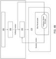
- FIG. 2 illustrates an exemplary image 110 including data regarding respiratory motion 120, catheter motion 130, reconstructed motion 140, and in-heart motion 150. This information is configured to be displayed on monitor 3. Each of these components is described in more detail herein.
- respiratory motion 120 refers to motion that is based on respiration data, which can be gathered or collected in various ways.
- probes, sensors, or patches (such as sensors 18 in FIG. 1 ) are attached to a patient's body or sensors are integrated with the catheter 14 that may be used in conjunction with external sensors 18. This data reflects the changes in volume of a patient's lungs.
- the respiration motion 120 can be based on movement of a patient's diaphragm during breathing.
- the signal can be extracted by placing electrodes on a body surface.
- the respiratory motion 120 is based on electrical signals between electrodes on a probe and patches on a body surface.
- the probes can measure displacement of one portion of the body relative to another portion of the body.
- a primary or major signal is generated by the sensors (such as sensors 18 in FIG. 1 ). This primary or major signal is then further processed and a derivative of the signal is determined. Respiration indicators and respiration vectors related to the respiratory motion 120 are described herein.
- the catheter motion 130 which is also known as probe or sensor motion or original catheter motion, illustrated in FIG. 2 reflects data regarding an absolute position of the catheter 14.
- This data can be generated using any known tracking or sensing configuration for a catheter, probe, sensor, etc.
- a magnetic field and sensor 29 on catheter 14 is in turn used detect the position of the catheter 14.
- catheter motion data can be obtained using magnetic transmitters external to a patient that generate signals based on a position of the catheter 14.
- the sensor configuration includes at least three magnetic sensors oriented in three different directions from each other that are mounted on a tip of the catheter and work in conjunction with a plurality of sensors that are external to the patient.
- an impedance sensor is provided and does not require any external sensors.
- the catheter motion data can be further processed via any combination of filters, smoothing, or post-acquisition signal processing.
- the reconstructed motion 140 of FIG. 2 is a control element in one aspect.
- the reconstructed motion 140 is generated in order to provide a validity and error check whether there is an undesirable amount of difference between itself and the original catheter motion 130.
- the reconstructed motion 140 is equal to the respiration motion 120 plus the original catheter motion 30.
- An error variable also referred to as ERR and described in more detail herein, can be determined based on the reconstructed motion 140 from the original catheter motion 130. Such determination based on the reconstructed motion 140 can be by subtraction or addition to the original catheter motion 130.
- the in-heart motion 150 is also referred to as the catheter-heart motion or probe-cavity motion.
- the in-heart motion 150 is measured in millimeters, but can be measured used any metrics.
- This motion data can generically refer to any type of motion data for a probe, catheter, or sensor relative to any wall or chamber of a chamber. This data can ultimately be used to determine site stability, specifically relating to ablation in a patient's heart.
- the in-heart motion 150 is typically important for a surgeon due to this information indicating when the catheter is stable relative to the heart chamber wall. With the in-heart motion 150, it is possible to find a stability point, also known as a stability location or site.
- the present disclosure is directed to providing more reliable and accurate mapping of in-heart motion 150 (i.e., catheter-heart motion or probe-cavity motion) based at least in part on respiration motion and other features, which addresses issues associated with any sudden movements occurring between end expiriums.
- in-heart motion 150 i.e., catheter-heart motion or probe-cavity motion
- the systems, methods, and processes are based on the following three features: (1) signal processing, (2) respiration compensation, and (3) station finding or site stability location.
- features (1) and (2) can be implemented without feature (3).
- feature (3) is specifically implemented in order to procedures involving the heart, and specifically involving ablation of specific areas of the heart. Any of the features described herein can used or adapted for determining aspects of chambers, and are not specifically limited to only being implemented with respect to heart chambers (i.e., navigation in the lungs).
- signal processing includes converting respiration indicators (RI) into a main respiration signal and its derivative, i.e., respiration vectors (RV).
- the respiration data is gathered based on the sensors in one embodiment, which can either include a catheter integrated with a sensor, external sensors, or any combination thereof.
- ablation effects are accounted for with ablation offset corrections, and low-pass filtering can be used to reduce heartbeat movement.
- the disclosed subject matter is based on decomposing catheter motion into two components: respiration motion and catheter-heart motion. Respiration motion is generally assumed to be correlated to RV via a correlation matrix A.
- Measured Motion Respiration Motion A ⁇ RV + Catheter ⁇ Heart Motion + ERR
- the correlation matrix A and the spline parameters are incrementally and simultaneously tuned in order to minimize root mean square (RMS) deviation between the measured motion after lower pass and the reconstructed motion in order to minimize the error.
- RMS root mean square
- the correlation matrix A is regressed in step n to match the respiration motion of step n-1, which is the total motion minus in-heart motion in step n-1.
- A is regressed in a current state to match the respiration motion of an earlier state, and the respiration motion is equal to the total motion minus the in-heart motion in the earlier state.
- the correlation matrix A is a two-row by three-column data set.
- the correlation matrix A is configured in one aspect to transform two-dimensional RV into an ellipsoid in three-dimensional space.
- the matrix values are tuned or selected so as to adapt by multiplication the RV values to the respiration ellipsoid size (i.e., in mm).
- the RV values are relatively small (i.e., 1.e -3 ) and these are multiplied by large values (i.e., 3,000) in the A matrix to create movement (i.e., 3.0 mm movement) in the three-dimensional space.
- the respiration motion there are five RI channels.
- the RI generally indicate lung motion and changes in lung volume overtime.
- the RI generally each contain similar signals and noise.
- the RI are collected by attaching a plurality of probes directly to a patient. For example, six patches or probes can be attached to a patient. Electrical signals between the six patches or probes are measured and the RI are generated. The electrical signals may include voltage, resistance, and/or impedance.
- the RI corresponding to each patch or probe may be provided in mV in one embodiment.
- RI are measures of the change in resistance (impedance) between patches, where the resistance is used via a temporal decomposition to extract the frequency band related to the respiration.
- the RI reflect the changes in the amount of air that flows into and exist in the lungs.
- the variation in airflow into and the air in the lungs may change the measurement of resistance between the patches (among the six patches).
- Filters can be applied to the RI in order to remove noise or other elements.
- a low pass finite impulse response (FIR) filter can be used to remove an imprint of the heartbeat on the RI signals.
- This step uses a 151-weight vector that is multiplied by 151 elements on each channel of raw data to produce one sample of filtered data, in one aspect. In other words, the filter multiplies the corresponding sample in a sliding window manner.
- FIR finite impulse response
- the singular value decomposition can be used to find the weights that select the most prominent respiration signal if multiplied by the measure five RI.
- This filtering step and processing step provides a smoother output signal and eliminates undesirable noise and disruptions caused by the heartbeat.
- the SVD is configured to extract the most prominent common motion out of several similar respiration dependent signals.
- the common signal is found as a linear combination of the individual RI signals.
- the SVD is done three times, including a first one on the first 30 seconds, a second one on the second 30 seconds, and third one on the entire 60 seconds of the RI buffer. In the event that the three sets of weights are similar enough, then the last set is selected.
- the similarity here refers to the V from the SVD. This V then becomes a weight vector, i.e., the RI2RV weights vector.
- the similarity parameter has a Pearson correlation of at least 0.5.
- this process involves determining the first Eigenvector in the SVD of five RI signals over several respiration cycles. For example, a sixty second buffer can be used, which can correspond to ten respiration cycles. By using multiple cycles, it can be assured that the RI signals are accurate and reliable.
- the disclosed subject matter also adds a phase shifted signal to provide ellipse-like motion or a model, shown by the estimated respiration motion 120 in FIG. 2 .
- This phase shifted signal is computed by finding the derivative of the RI signals and combining the derivative using the same weights. This process is analogous to a phase shift between a Cos(x) function and Sin(x) function.
- respiration vectors are produced based on the main respiration vector and a derivative of the main respiration vector.
- Equation 2 is generally similar to Equation 1, except Equation 2 uses RV instead of Rl.
- raw location data regarding the catheter is filtered.
- the raw location data is filtered using the same low pass FIR filter that was applied to the RI signals to remove the heartbeat motion.
- synched and filtered respiration vectors and the catheter location are generated.
- This feature generally includes estimating a correlation matrix A and spline parameters that represent the catheter's actual motion. The two RV are then transferred into a three-dimensional space.
- the processes disclosed herein generally transfer this 2D vector into a 3D ellipse or ellipsoid in 3D space, as shown by element 120 in FIG. 2 .
- the ellipse drawn in FIG. 2 can be oriented in any direction, and the main purpose of compensating for respiration involves modeling movement of a patient's breathing on the catheter or probe.
- the correlation matrix A (also referred to as the transformation matrix) converts the two-dimensional vector into a three-dimensional ellipsoid.
- the correlation matrix A is determined based on regression, in one aspect.
- the root mean square error (RMSE) is minimized between the modeled motion (i.e., respiration motion + catheter motion) and the measured motion to provide the correlation matrix A.
- a system 200 that includes a site stability module 210.
- This system 200 can be implemented, integrated, or configured to interface with the computing system 4 shown in FIG. 1 .
- the term module can refer to any computational component or interface, and can include any hardware component or software component.
- the site stability module 210 can include any one or more of the features disclosed herein.
- the site stability module 210 is configured to receive data from various inputs. For example, location data 202, respiration indicator data 204, status data 206 (such as location status and status of the Rl), and initialization or algorithm parameters 208 can each be provided to the site stability module 210.
- the data is provided streaming in 16.67 ms intervals.
- One skilled in the art will understand based on this disclosure that the data steaming parameters and cycles or periods can vary.
- session stability time segments 212 i.e., start-end segments
- catheter-heart location data 214 are transmitted to a central module 220.
- the site stability module 210 provides output parameters that include the last stability segment parameter and parameters of the last set of sites in the last ablation session.
- stability is a segment of duration of three seconds or greater in which the catheter-heart speed is below a certain speed threshold.
- the site is part of the stable segment during ablation time, and a segment of stability during ablation can be divided into several sites.
- the central module 220 can include any centralized computing system configured to receive, process, and/or transmit data to and from the site stability module 210.
- the central module 220 is a CARTO VISITAG TM processing unit.
- CARTO VISITAG TM processing unit One skilled in the art would understand that various types of configurations can be provided that are in communication with the site stability module 210.
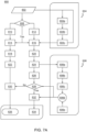
- the process 300 generally includes two distinct phases for site stability, a pre-processing phase 310 and a stability detection phase 330.
- Preprocessing phase 310 is the stage generally where the raw signals from the measurements are filtered and transformed providing a filtered catheter motion vector and a respiration vector. The filtered catheter motion may still include a respiration factor.
- Decomposition 350 which is during the stability detection phase 330 is where the filtered catheter motion is separated into respiration motion and respirator free catheter motion.
- Stability detection phase 330 is the stage in which sliding motion is used to detect ablations stations inside stable segments during an ablation. Preprocessing phase 310, decomposition 350 and stability detection phase 330 are described in more specific detail below.
- the pre-processing phase 310 includes at least two groups of channels: the location channels, and the RI channels.
- This data can be set or generated in relatively small increments. For example, the data can be set at least every 16.67 ms.
- the location data 312 is further processed.
- the location data 312 can be processed by applying a low pass filter or low pass FIR filter at step 316.
- the filtered location i.e., the last filtered location, is determined at step 324.
- the RI 314 can also be further processed through a series of steps or processes 318, 320, and 322. As shown in FIG. 3A, the RI 314 can first be analyzed for ablation corrections at step 318, which accounts for any offset caused by the ablator.
- the offset from the ablator affects the ability to estimate respiration motion. Accordingly, reducing the effect of the offset provides an accurate output regarding the RI 314.
- an ablation offset correction factor is determined by measuring RI signals prior to ablating and during ablating. Whenever the ablator is turned on, then the estimated offset per channel is compensated (e.g., subtracted or added) from the RI signals.
- the offset is estimated based on the RI signal change between the RI signals measured just before ablation starts to the RI signals measured just after the ablator start.
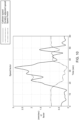
- the effect of the ablation offset is shown in FIG. 5 , which illustrates an ablation offset by the shift in the RI during ablation.
- the filters include a low pass filter and a derivative filter.
- the low-pass filter and derivative filters are configured as FIR filters with 151 sample kernel.
- preprocessing includes the following steps. First, the original five RI channels are obtained. Second, ablation offset correction is performed. Third, low-pass and derivative pass filters are performed to create filtered respiration indicators (FRI) and derivative respiration indicators (DRI) using a sliding window of 151 samples of FIR filter. Fourth, the SDV is performed to find the most prominent weights. Fifth, the most prominent weights are implemented on the FRI to obtain RV(1) and on the DRI to obtain RV(2).
- FRI respiration indicators
- DRI derivative respiration indicators
- FIG. 6 illustrates one example of filters that can be used at step 320, and illustrates the weights for a low pass filter and for its derivative signal. As shown in FIG. 6 , different weighted factors are applied over time for the low-pass filter and the derivative filter.
- the data regarding the RI 314 is further processed at step 322 by calculating the first Eigenvector of the RI 314 and by calculating the derivative of the first Eigenvector of the RI 314.
- the SVD is used to find the first Eigenvector of the filtered RI in order to reduce redundancy and noise.
- the mean compensated (e.g., subtracted or added) filtered respiration indicators (FRI) and the derivative respiration indicators (DRI) can be stored. In one embodiment, this information is stored in one-minute buffers. One skilled in the art would understand that the buffer duration can vary.
- the SVD is only performed once at the beginning of a predetermined period when the buffers are full with a valid signal.
- the SVD produces five coefficients of a first Eigenvector (V1), and the five coefficients are used to produce the respiration vectors (RV) at step 326.
- the RV equal is equal to FRI x V1, DRI x V1.
- the last minute of the RV data (produced at step 326) and the filtered location data produced at step 324, are synchronized and stored in the last-minute buffer.
- Data from steps 324 and 326 is provided to the stability detection phase 350.
- motion decomposition 352 is carried out. More detail regarding motion decomposition is provided by FIG. 7B .
- the process includes calculating site stability and sites 354. This step provides data back to a site stability module 210, which is configured to receive catheter motion data and provide session motion data. Information regarding catheter motion and site information is stored with the site stability module 210. Site stability parameters can be recalculated based on the information provided to the site stability module 210.
- a pre-processing phase starts with obtaining a data set, i.e., step 602.
- the data set can include the RI, locations, statuses and various other information.
- the buffer at step 604a can include a 1.5 second buffer of the RI signals to enable fast estimation.
- the buffer can include at least 151 samples of RI signals.
- the parameters for accounting for the effect of ablation on the RI signals can vary depending on specific circumstances, such as the number of RI channel signals, ablation strength and duration, characteristics of the patient, etc.
- Data from step 604c is ultimately sent to step 616, described in more detail below.
- a validation step 608 is carried out to determine if the data set is complete.
- the computing system 4 or a manager in a software module confirms the validity of the data.
- the term manager can refer to any computational interface, such as an interface within CARTO ® VISITAG TM processing unit or central module 220. This component is configured to insert or input data and to also receive an output of data. In the event that the data is invalid, the manager sends a reset or soft-reset signal to the algorithm processor to empty all of the buffers and begin filling the buffers again with new data if errors are detected. The algorithm ensures that the buffers are full with valid data before progressing to a subsequent step.
- step 614 includes 151 ⁇ 3 samples.
- step 616 includes 151 ⁇ 5 samples.
- the location filter buffers and the RI filter buffers are also updated, as described with respect to steps 614 and 616, but the buffers do not need to be reset.
- the location data and the RI signal data both undergo a filtering step.
- the location data from step 614 is filtered at step 618.
- the filter at step 618 is a low-pass FIR filter.
- the RI signal data from step 616 is also processed.
- the filter at step 612 is a low-pass and derivative FIR filter.
- Step 622 which follows step 618, then updates location buffers.
- Step 624 follows step 620 and includes updating RI buffers.
- the location data is further processed at step 626, which includes obtaining a last-minute buffer, and obtaining filtered catheter motion.
- phase 606 includes transforming every sample in the 5D FRI vectors into their first Eigenvector using the Eigenvector coefficients in vector V.
- vector V is a five-element vector of weights that multiple the five Rls to obtain the most prominent respiration vector.
- Step 606a includes measuring breaks in the derivative RI (DRI) signal.
- Step 606b includes checking that there is no respiration gap and the data is valid.
- Step 606c includes calculating V using the SVD. The SVD is calculated only once the FRI buffer is full with valid numbers and no respiration gap was found. In one embodiment, this step can include calculating V in one second intervals. Once V is obtained at step 606d, then the data can be further processed at steps 628 and 632.
- Step 606e is a validity check, and if a soft-reset signal was received, then vector V is reset to zero.
- Calculating V includes the following steps. Once the RV buffers are full, a two second test can be performed to determine if there are any respiration gaps (i.e., due to apnea) inside the DRI buffer. If the buffers are full and there are no gaps, then a calculation is carried to out to determine three different V by three different SVDs: one on the first 30 seconds, one on the last 30 seconds, and one on the entire 60 seconds DRI buffer.
- the 60 second V is selected as the new V going forward.
- the process verifies that the minima of the resulting respiration signal RV(1) is correlated to a maxima of the y-location of the probe.
- the minima of the respiration signal (RV1) is preferred to represent the end-expirium (as compared to the in-expirium).
- the corresponding Y-values of the catheter location are checked and the process ensures that the Y values in the respiration minima is larger than the Y values in the respiration maxima because the Y value is maximal in humans at end-expirium times.
- the Y-direction in is oriented in a heart-head direction in a patient as the patient lays on their back.
- step 634 includes the last-minute buffer that was used in step 626, to provide RV.
- FIG. 7B shows the steps for motion decomposition according to one aspect.
- smooth(x) generally refers to a mathematical smoothing function, which can be implemented according to any computer interface, electronics, or programming tool, such as MATLAB ® .
- Various other functions, such as “smooth,” “exp,” “pinv,” “spline,” “rms,” “norm,” etc., used herein may be implemented using any known computer interface, electronics, or programming tool, such as MATLAB ® .
- These computer interfaces, electronics, or programming tools are generally configured to provide matrix, array, and data manipulation, plotting functions, data implementation, and/or algorithm implementation.
- smooth refers to a method of noise reduction or a data set in one aspect.
- the smoothing function uses a moving average, a filter, or uses a smoothing spline.
- spline(x) refers to a function that calculates, returns, or generates a vector having interpolated values that correspond to points of an array, matrix, or dataset x.
- a cubic spline interpolation can be used.
- the term "exp(x)" as used with respect to functions or equations herein refers to an exponential function e x and determines each element in an array, matrix, or dataset x.
- pinv(x) refers to a function that calculates, returns, or generates a Moore-Penrose Pseudoinverse of an array, dataset, or matrix x.
- the term "norm(x)" as used with respect to functions or equations herein refers to a function that determines a scalar or magnitude value, and calculates, returns, or generates a measure of magnitude of elements in an array, matrix, or dataset x.
- maximum(x) refers to a function that calculates, returns, or generates the maximum elements of an array, matrix, or dataset x.
- the term "rms(x)" as used with respect to functions or equations herein refers to a function that calculates, returns, or generates the root-mean-square of an array, matrix, or dataset x.
- Any one or more of the function terms used herein can be implemented using any computational element or software program configured to perform computational analysis and functions.
- One such example of a program is MATLAB ® .
- One skilled in the art would understand these mathematical or programming functions, and equivalents or variants thereof, can be implemented to carry out specific functions, calculations, or manipulations of the data, matrices, arrays, and information described herein.
- Any of the functions described herein can be implemented on the computing system 4, or any other electrical or computer hardware and software.
- Decomposition is calculated every 100 ms in one embodiment. These 100 ms segments can be calculated on the entire last minute of data in order to allow for slow adaption of the correlation matrix A over the last minute.
- two versions of the catheter-heart motion are used by controlling the curvature of the spline.
- intermediate catheter motion is calculated with a single curvature or smoothing parameter.
- Step 638 includes estimating the intermediate catheter motion with the following calculation: Smooth(FCM-RCV). This smoothing parameter limits the speed of the spline direction change and this is equivalent to assume slow accelerations.
- the intermediate catheter motion is used in the estimation of the correlation matrix A. Specifically, the correlation matrix A is tuned using segments with slow intermediate catheter motion speed (i.e., slow segments). On these slow segments, the catheter acceleration is small with respect to the respiration motion, and the correlation matrix (A) is estimated more accurately.
- the intermediate catheter motion is estimated using a smoothing function to limit the resulting curvature.
- T0 is a vector of reference time (0 to 60 seconds in 0.1 second increments).
- the inaccuracy is estimated by the norm function of the estimation error.
- SmoothP is a smoothing parameter that limits the spline curves second derivative (i.e., acceleration), and is generally defined as a smoothing parameter to control the curvature through a segment.
- SmoothV is generally defined as smoothing vector to control curvature per data point.
- the slow accelerations i.e., the intermediate catheter motion (ICM)
- ICM intermediate catheter motion
- CM catheter motion
- the ICMerr or error of the ICM is an estimation error and this is equal to Norm(FCM-RCV-ICM).
- the ICMerr is used to estimate the accuracy of the reconstruction of the FCM. Based on this, the spline is corrected when the error of slow motion is high.
- the smoothing function smooths data using a moving average filter.
- catheter motion is the corrected ICM using the correction vector (SmoothV) and allows fast acceleration where the intermediate catheter motion is determined to be inaccurate.
- This correction vector (SmoothV) allows different curvatures (i.e., accelerations) at different spots along the last minute of data.
- the CM equals: Smooth(T0, (FCM-RCV), SmoothP, smoothV). This process is a way to force the smooth function to be more flexible, which allows for larger curvature in points where the reconstructed error is larger.
- Step 650 includes estimating the catheter motion based on the following equation: Smooth(FCM - RCV,SmoothV).
- a function or process is carried out to smooth the catheter motion with a spline model by limiting the spline curvature (i.e., the second derivative of the curvature).
- smoothP ⁇ ⁇ j 1 n xyz j ⁇ f j 2 + 1 ⁇ smoothP ⁇ ⁇ smoothV t D 2 f t 2 dt
- Equation 3 D 2 f denotes the second derivative of the function f.
- the parameter smoothP controls the smoothing strength.
- the whole concept of smoothing in this aspect is balancing between two contradictory elements.
- the first element generally tries to remain true or accurate to an input vector even when there is noise (i.e., many inconsistent direction changes).
- the second element is to be as smooth as possible with minimal direction and speed changes.
- SmoothV is a vector of values that directs the smooth function to prefer the first element over the other, or vice versa, in different parts of the input vector. So as SmoothV values are closer to 0, the smoothing function should be more accurate and less smooth.
- smoothV allows smoothP in Equation 3 to be localized.
- catheter motion is used for site segment detection at step 652.
- catheter motion and site segment detection data are sent to a central module 655 that is configured to store data regarding the site segment and catheter motion.
- An iterative process is then carried out that analyzes session motion, and recalculates the ablation site.
- the ablation is divided into sites and is recalculated in every step, and can vary significantly according to compensated catheter-heart motion. This catheter compensated location can be saved in a central module or storage unit for site recalculation after a user or surgeon has adjusted various control parameters.
- Step 640 includes calculating the RCV in the last minute of information and data.
- the RCV A x RV.
- correlation matrix A is also identified as RV2RCV.
- Estimating the correlation matrix A is generally performed using weighted mean squares and matrix inversion according to one embodiment.
- the weights (W) used in these calculations reflect how each data point in the last minute is configured to estimate the correlation matrix A according to at least one of the following criteria: (i) weight decay with time, (ii) preference for slow intermediate catheter motion speeds, (iii) RV validity, and (iv) duration of time from ablation.
- Respiration apneas are segments of time in which the respiration signal, i.e., the RV, is reduced due to apnea or other forms of shallow respiration. Due to their influence, the correlation matrix A should generally not be estimated during these segments.
- weight associated with each sample which includes RV and location data
- Weights during shallow respiration i.e., small RV signals are zeroed, which eliminates the impact of these measurements on the overall estimation and correlation matrix A.
- FIG. 8 illustrates the effect of apnea on the RV during ablation.
- a gap in respiration is generally defined as time segments in which the respiration derivative cannot reach a predetermined extreme value and can only reach below 85% of the predetermined extreme value.
- these small and large parameters are defined by analyzing the 15 - 85 percentiles, and ignoring signals above and below these percentiles. Consecutive samples that are within the 15-85 percentiles are counted and analyzed. If the signal in a continuous segment happens to occur inside these thresholds and not crossing them, then the segment of all the samples in this continuous segment is indicated as a respiration gap, i.e., a shallow breath, and therefore can be discarded.
- the percentile values are selected over the last minute of data and define thresholds for the respiration derivative amplitude. When the respiration derivative signal is between the thresholds for a predetermined period, such as 5 seconds (which corresponds roughly to one respiration cycle), then the respiration signal is considered too weak and therefore should be discarded.
- the percentile values can be modified and generally selected to identify shallow respiration. One skilled in the art would understand that other filtering or analysis can be used to identify shallow respiration.
- estimating stability weights are provided herein.
- the decomposition process into respiratory related motion and catheter related motion is performed more accurately when the catheter is relatively stable or is slowly sliding against another surface, i.e., tissue. Identifying relatively stable segments is important for producing a reliable output.
- Stable segments are generally defined herein as segments of time in which the intermediate catheter motion speed is relatively slow (i.e., ⁇ 2.5 mm/sec) for a specific period of time (i.e., > 3-5 seconds).
- Estimating the correlation matrix A is carried out using the stable segments or essentially stable segments. Stable segments are emphasized due to the assignment of higher weights for samples during stable times.
- Stability weights are converted into a vector of numbers that correspond to the last minute and represents the point relevancy for the correlation matrix A estimation (i.e., the RV2RCV matrix). Besides speed stability, factors regarding recency (i.e., the age or how old a segment is) and data segments collected during ablation are also considered. Recent samples receive higher weights than older samples, and ablation segments receive higher weights than non-ablation segments.
- FIG. 9 illustrates one aspect of the recency factor with respect to stability weights. As shown in FIG. 9 , higher weights are assigned to more recent samples (i.e., the right-hand side of the graph) and the older samples receive a lower weight. As shown in FIG. 9 , a sigmoid provides a smooth transition between recent and older signals.
- FIG. 10 illustrates one aspect of the speed factor with respect to stability weights. As shown in FIG. 10 , higher weights are used when the catheter estimated speed is low, and lower weights are used when the catheter estimated speed is high. In one aspect, the weights are decreased when the low speed duration is shorter than an average respiration cycle. As shown in FIG. 10 , the duration is adjusted by artificially increasing the estimated speed.
- FIG. 11 illustrates one aspect of the ablation factor with respect to stability weights.
- higher weights are assigned to signals when ablation is occurring, as shown in FIG. 12 .
- the three factors described above with respect to FIGs. 9 , 10 , and 11 are used to generate the total stability weights.
- the total stability weights vector can be a sample by sample product of all three factors.
- FIG. 12 illustrates how the stability weight factors can be measured over time.
- the recency factor is only calculated at the initialization because this factor is fixed.
- A(2x3) transforms the RV (two columns matrix representing the respiration signal and its derivative) into the RCV (three column matrix representing the X-Y-Z of the respiration matrix).
- the correlation matrix A at step 646 is then sent back to step 636 in order to provide a circuitous or continuous cycle for continuously estimating and updating the correlation matrix A.
- the process in FIG. 7B is iterative, such that the correlation matrix A is constantly updating and becoming more accurate through each iteration.
- the 3D RCV can be modeled as a product of the 2D RV (which equals the main respiration signal + a phase shift) and the correlation matrix A (2x3).
- the parameters of the correlation matrix A are estimated based on the RV, a rough estimation of the respiration vector (which equals the filtered catheter motion minus the intermediate catheter motion), and the stability weights vector by minimizing the mean square error.
- the correlation matrix A is generated as an output.
- the intermediate catheter motion assumes relatively slow accelerations of the catheter, and cannot represent the true catheter motion in segments of high speed.
- An intermediate catheter motion error factor can be estimated based on segments of faster motion. Catheter motion is recalculated while increasing the curvature for high speed segments to allow for fast motion as well.
- the ICM error (ICMerr) Norm(FCM - ICM - RCV).
- the respiration data equals total catheter motion minus intermediate catheter motion
- total catheter motion minus respiration equals in-heart catheter motion.
- ICMerr is the per sample Euclidian distance in R3 between the measured location FCM and the slow model reconstructed location ICM + RCV. SmoothV is used to correct the intermediate catheter motion to find the in-heart catheter motion, in one aspect.
- Station finding also known as location finding or site finding, generally includes identifying periods when the catheter or probe is stable. This process includes performing logic and functions that produce stations' time edges and center locations based on the compensated motion. The stations in the last session are continuously updated along with the correlation matrix A and the resulting compensated motion. Stability is generally defined as a continuous segment of time in which the estimated catheter speed is below a user predefined threshold.
- the catheter speed is calculated by taking a derivative of the catheter position over the last minute.
- the last-minute locations are updated at least every 0.1 second, and are saved for the whole minute. These values can vary depending on the specific requirements of a particular application.
- the last catheter speed value from this buffer is saved and accumulated in the last speed buffer.
- the end-5 value in the catheter speed buffer is the speed of the catheter using the end-5 and end-7 values in the catheter one-minute locations buffer that were updated in current iteration.
- the end-5 value in the last speed buffer is the last catheter speed that was calculated 5 iterations ago.
- a minimum value of the catheter speed and the last speed over the last minute is defined as the minimal speed, and is used to detect when the catheter is stable.
- a minimal speed buffer includes all the minimum speeds that were estimated during the last minute. Segments of continuous speed that are smaller than a threshold speed are identified in this buffer, while trying to find a time period when the catheter was stable.
- any determination regarding stability can be delayed for at least one second, and this predetermined delay can vary.
- Boundaries of a current stable segment can be updated and then terminated if necessary. If a current stable segment was not found or if it was previously terminated, then a search for new stability segment in the recent several seconds of the estimated catheter motion is carried out.
- the boundaries are updated according to an updated minimal speed buffer.
- the starting point of the current stable segment can also be updated by looking backwards from the last index of stable segments until the earliest point when the speed is lower than a threshold.
- the ending point of the stability segment can be updated by looking forward from the last index of a stable end until the latest point that the catheter speed is lower than a threshold.
- a stable segment is not terminated until a predetermined period (i.e., roughly one second) occurs from the current time in order to avoid terminating segments due to edge inaccuracy. If a stable segment was not yet found, then the search for stability from the current time backward is carried out to find the earliest moment when a predetermined threshold was crossed.
- a predetermined period i.e., roughly one second
- the present disclosure also is directed to defining a localized segment as a time segment in which all its points (i.e., distance from its own center of gravity) are below a threshold.
- a localized segment as a time segment in which all its points (i.e., distance from its own center of gravity) are below a threshold.
- the XYZ mean of the curved line can be calculated and this is the center of gravity. From this value, it is possible to calculate the distance from center (DFC) for every point on the line.
- This process involves locating a site (i.e., a time segment) when the ablator is on and the catheter is both stable and localized.
- a site i.e., a time segment
- a stable time segment during ablation is identified.
- the processes and algorithms disclosed herein can divide, segment, or otherwise split the stability segment during ablation into localized segments (i.e., sites) for which the maximal DFC is below a predetermined threshold.
- the predetermined threshold is 3.0 mm.
- the algorithm for splitting the stability segment into sites essentially obtains the minimal number of sub-segments that maintain a localization criterion. In one aspect, it is a recursive function that ceases or stops in the event that the current sub-segment is localized. In one embodiment, this involves determining whether the maximum DFC is less than a threshold, i.e., 3.0 mm in one aspect.
- an algorithm that essentially splits or segments a curve in 3D dimensional space (i.e., the in-heart motion 50, catheter-heart motion, probe-cavity motion, etc.) into localized curves.
- curve is defined as a vector of XYZ coordinates in 3D space that represents the course of motion of an object.
- this process involves determining the center of gravity of a curve defined by a data set, in which the center of gravity is defined as a point in 3D space that represents the mean value of each coordinate of the curve.
- the DFC is defined as a one-dimensional vector that represents the Euclidean distance between each point in the curve relative to the center of gravity, in one aspect.
- a localized curve is defined as a curve for which a maximum DFC is smaller than a predetermined threshold distance. In one aspect, this distance is 3.0 mm.
- defining a split curve of 3D dimensional data is a recursive function.
- This defining a split curve is provided in the flow diagram 1300 of FIG. 13 .
- the flow diagram 1300 includes finding a central localized curve based on the obtained data at 1310 (i.e., in-heart motion 50, catheter-heart motion, probe-cavity motion, etc.).
- Step 1310 can include determining whether a test curve (i.e., input curve) defined by the data set is localized at 1320, i.e., whether a maximum DFC is smaller than a threshold.
- the test curve which is basically a potential candidate for the central localized curve, is iteratively cut from either side until it is localized and therefore declared or identified as the central localized curve.
- an input curve or the initial test curve will be the localized immediately, and therefore the cutting step can be omitted.
- the input curve is the central localized curve, and therefore the splitting algorithm is not required.
- Flow diagram 1300 checks whether any curves exist before the central localized curve at 1380. In one aspect, this step is performed based on the excluded or set aside pre-central points (disclosed above with respect to an index comparison step) by using a splitting function in a recursive manner. The process generates a list of pre-central localized curves for analysis at 1390 based on 1380. Flow diagram 1300 checks whether any curves exist after the central localized curve at 1385. In one aspect, this step is performed based on the excluded or set aside post-central points by using a splitting function in a recursive manner. The process generates a list of post-central localized curves for analysis at 1395 based on 1385.
- the list of all localized curves includes preceding localized curves, central localized curves, and proceeding localized curves at 1399.
- the algorithm essentially segments or breaks a 3D curve into a number of localized curves for further analysis.
- the analysis determines whether curves have a maximal DFC that is less than a predetermined distance threshold.
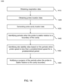
- FIG. 14 illustrates a flow diagram illustrates various steps for a method 1400 for accounting for or minimizing the impact of the respiration component in the catheter motion data.
- step 1410 includes obtaining respiration data.
- This data can be obtained by sensors attached to a patient's body.
- this data is obtained by a series of patches or sensors (i.e., sensors 18 from FIG. 1 ) attached to a patient's body that are configured to detect impedance values based on the patient's lungs filling with air.
- this data is obtained via a sensor arrangement including a catheter integrated with a sensor as well as external sensors, or solely based on a sensor integrated with a sensor.
- Breathing is generally based on a patient's diaphragm moving up and down, which also displaces the patient's heart. Accordingly, obtaining the respiration data is important for mapping the motion of a catheter within a patient's heart during respiration.
- Step 1420 includes obtaining probe location data, which can be generated via any known tracking method or system.
- the probe location data can also be obtained using sensors (i.e., sensors 18 from FIG. 1 ) attached to a patient's body.
- the sensors are configured to generate a magnetic field and motion of the catheter inside of patient can generate magnetic signals to indicate a position of the catheter.
- Step 1430 includes generating probe-cavity location data by compensating (e.g., subtracting or adding) the respiration data from the probe location data.
- Step 1440 includes identifying periods when the probe is stable relative to a boundary of the cavity.
- Step 1450 includes identifying site stability sites based on the periods when probe speed is less than a predetermined speed for a predetermined period.
- the predetermined speed can be 2 mm/second and the predetermined period can be at least three seconds.
- the method 1400 includes applying a filter to the respiration data and the probe location data.
- Step 1460 includes notifying a surgeon of the periods when the probe is stable relative to the cavity boundary.
- This step can include providing notifications via visual alerts or indicia (which can be displayed via monitor 3), audio alerts or indicia (which can be played via computing system 4), or any other notification such that the surgeon is informed of the stable periods.
- markers, tags, or visual indicators are overlaid or inserted onto a three-dimensional mapping or image of the location data and are displayed on a monitor (e.g., monitor 3 in FIG. 1 ).
- Step 1410 can further include converting respiration indicators by using singular value decomposition (SVD) to obtain a first Eigenvector and a first Eigenvector derivative.
- the first Eigenvector can correspond to a primary respiration signal and the first Eigenvector derivative can correspond to a phase shifted respiration signal.
- the method 1400 can include transferring the primary respiration signal and the phase shifted respiration signal from two dimensions into a three-dimensional ellipsoid based on a correlation matrix.
- the method 1400 can also include determining the correlation matrix by calculating a root mean square deviation between the probe location data and the probe-cavity motion data.
- the method 1400 can include determining the correlation matrix based on weighted factors including at least one of: (i) age of the respiration data; (ii) speed of the probe; (iii) depth of respiration; or (iv) data obtained during ablation.
- the method 1400 includes generating an image including estimated respiratory motion based on the respiration data, probe motion based on the probe location data, and probe-cavity motion based on the probe-cavity location data. This image can then be displayed on a monitor to a surgeon, along with indicators, tags, or visual indicators showing periods when the probe is stable relative to the cavity boundary.
- FIG. 15 illustrates a method 1500 of capturing mapping data with respiration compensation.
- the predetermined speed of the probe location data may be small, and even may be zero.
- the input for the ablation is also zero. Therefore, in such a configuration, the movement of the electrodes in relation to the tissue wall may largely be a result of respiratory motion.
- the signal(s) from multiple electrodes are recorded over a period of about 2.5 seconds.
- the beating of the heart may be accounted for.
- the duration accounting for the beating of the heart the movement due to respiration is the main remaining factor effecting the mapping. This movement due to respiration can cause a smearing of the data.
- the respiration movement can be compensated for.
- this motion can be significant. Since the respiration motion is known and understood, as described above, the mapping points collected during the respiration motion may be compensated for. For example all of the points captured during the respiration cycle may be adjusted to the end of respiration phase to produce a better anatomical mapping (less blurry). In such a configuration, by adjusting the data points to remove the respiration movement, the picture clarity is improved. As will be understood, the compensation of the mapping points could be positioned at a reference point during any portion of the respiration cycle, including the beginning, the midpoint, or any other portion of the respiration cycle. The end of the respiration is used as an example to aid in the understanding of the description. This data collection may be referred to as compensated motion to mapping.
- the stability of each electrode may be monitored as described herein.
- the stability is used to determine the mapping values. This determination may include at least one of adjusting the mapped data points based on the stability and only computing mapping values for electrodes that are deemed to be stable. For example, when a data collection occurs, the data from stable electrodes may be recorded, while the less than stable electrodes are excluded, or have their data recollected.
- a weighting system may be used based on the level of stability in collecting the data. In either example - the wait or the weight, which may also be employed in unison, the data is improved and less blurry. Using a gating function based on the stability the data collected is of improved quality.
- respiration data may be obtained.
- the respiration data may be obtained.
- This data can be obtained by sensors attached to a patient's body.
- this data is obtained by a series of patches or sensors (i.e., sensors 5 from FIG. 1 ) attached to a patient's body that are configured to detect impedance values based on the patient's lungs filling with air.
- this data is obtained via a sensor arrangement including a catheter integrated with a sensor as well as external sensors, or solely based on a sensor integrated with a sensor. Breathing is generally based on a patient's diaphragm moving up and down, which also displaces the patient's heart. Accordingly, obtaining the respiration data is important for mapping the motion of a catheter within a patient's heart during respiration.
- respiration data may be converted to indicators by using singular value decomposition (SVD) to obtain a first Eigenvector and a first Eigenvector derivative.
- the first Eigenvector can correspond to a primary respiration signal and the first Eigenvector derivative can correspond to a phase shifted respiration signal.
- the method 1400 can include transferring the primary respiration signal and the phase shifted respiration signal from two dimensions into a three-dimensional ellipsoid based on a correlation matrix.
- the method 1400 can also include determining the correlation matrix by calculating a root mean square deviation between the probe location data and the probe-cavity motion data.
- the method 1400 can include determining the correlation matrix based on weighted factors including at least one of: (i) age of the respiration data; (ii) speed of the probe; (iii) depth of respiration; or (iv) data obtained during ablation.
- the method 1400 includes generating an image including estimated respiratory motion based on the respiration data, probe motion based on the probe location data, and probe-cavity motion based on the probe-cavity location data. This image can then be displayed on a monitor to a surgeon, along with indicators, tags, or visual indicators showing periods when the probe is stable relative to the cavity boundary.
- FIG. 16 illustrates a plot 1600 of respiration data points with and without respiration compensation.
- Plot 1600 includes data in the X-axis from -5 to +5 mm.
- Plot 1600 includes data in the Y-axis from -4 to +4 mm.
- data points 1610 represent data with no respiration compensation.
- Data points 1620 represent the same data with compensation.
- the data points 1620 include points where the data is shifted from the continuum of the respiration cycle to a point say at the end of the cycle.
- the data points 1610 without respiration compensation have a Y-axis spread of approximately 8 mm and an X-axis spread of approximately 5 mm.
- Data points 1620 with the compensation have a Y-axis spread of less than 0.5 mm and an X-axis spread of less than 0.5 mm.
- the disclosed subject matter is not limited to being used in connection with a heart.
- the disclosed subject matter can be used in a variety of applications to analyze features of any type of object, such as a chamber.
- processors include, by way of example, a general-purpose processor, a special purpose processor, a conventional processor, a digital signal processor (DSP), a plurality of microprocessors, one or more microprocessors in association with a DSP core, a controller, a microcontroller, Application Specific Integrated Circuits (ASICs), Field Programmable Gate Arrays (FPGAs) circuits, any other type of integrated circuit (IC), and/or a state machine.
- DSP digital signal processor
- ASICs Application Specific Integrated Circuits
- FPGAs Field Programmable Gate Arrays
- Such processors can be manufactured by configuring a manufacturing process using the results of processed hardware description language (HDL) instructions and other intermediary data including netlists (such instructions capable of being stored on a computer readable media).
- HDL hardware description language
- netlists such instructions capable of being stored on a computer readable media.
- the results of such processing can be maskworks that are then used in a semiconductor manufacturing process to manufacture a processor which implements features of the disclosure.
- Non-transitory computer-readable storage mediums include a read only memory (ROM), a random-access memory (RAM), a register, cache memory, semiconductor memory devices, magnetic media such as internal hard disks and removable disks, magneto-optical media, and optical media such as CD-ROM disks, and digital versatile disks (DVDs).
- ROM read only memory
- RAM random-access memory
- register cache memory
- semiconductor memory devices magnetic media such as internal hard disks and removable disks, magneto-optical media, and optical media such as CD-ROM disks, and digital versatile disks (DVDs).
Landscapes
- Health & Medical Sciences (AREA)
- Life Sciences & Earth Sciences (AREA)
- Engineering & Computer Science (AREA)
- Molecular Biology (AREA)
- Animal Behavior & Ethology (AREA)
- Veterinary Medicine (AREA)
- Biophysics (AREA)
- Pathology (AREA)
- Public Health (AREA)
- Biomedical Technology (AREA)
- Heart & Thoracic Surgery (AREA)
- Medical Informatics (AREA)
- General Health & Medical Sciences (AREA)
- Surgery (AREA)
- Physics & Mathematics (AREA)
- Physiology (AREA)
- Signal Processing (AREA)
- Artificial Intelligence (AREA)
- Computer Vision & Pattern Recognition (AREA)
- Psychiatry (AREA)
- Cardiology (AREA)
- Dentistry (AREA)
- Oral & Maxillofacial Surgery (AREA)
- Nuclear Medicine, Radiotherapy & Molecular Imaging (AREA)
- Radiology & Medical Imaging (AREA)
- Pulmonology (AREA)
- Measurement And Recording Of Electrical Phenomena And Electrical Characteristics Of The Living Body (AREA)
Applications Claiming Priority (1)
| Application Number | Priority Date | Filing Date | Title |
|---|---|---|---|
| US18/523,526 US20250169765A1 (en) | 2023-11-29 | 2023-11-29 | Respiration compensation for mapping |
Publications (1)
| Publication Number | Publication Date |
|---|---|
| EP4566533A1 true EP4566533A1 (de) | 2025-06-11 |
Family
ID=93741950
Family Applications (1)
| Application Number | Title | Priority Date | Filing Date |
|---|---|---|---|
| EP24215980.4A Pending EP4566533A1 (de) | 2023-11-29 | 2024-11-28 | Atmungskompensation für mapping |
Country Status (5)
| Country | Link |
|---|---|
| US (1) | US20250169765A1 (de) |
| EP (1) | EP4566533A1 (de) |
| JP (1) | JP2025087651A (de) |
| CN (1) | CN120052873A (de) |
| IL (1) | IL317029A (de) |
Citations (24)
| Publication number | Priority date | Publication date | Assignee | Title |
|---|---|---|---|---|
| US5391199A (en) | 1993-07-20 | 1995-02-21 | Biosense, Inc. | Apparatus and method for treating cardiac arrhythmias |
| US5539119A (en) | 1990-06-05 | 1996-07-23 | Toray Industries, Inc. | Indole derivatives |
| US5558091A (en) | 1993-10-06 | 1996-09-24 | Biosense, Inc. | Magnetic determination of position and orientation |
| US5944022A (en) | 1997-04-28 | 1999-08-31 | American Cardiac Ablation Co. Inc. | Catheter positioning system |
| US5983126A (en) | 1995-11-22 | 1999-11-09 | Medtronic, Inc. | Catheter location system and method |
| US6172499B1 (en) | 1999-10-29 | 2001-01-09 | Ascension Technology Corporation | Eddy current error-reduced AC magnetic position measurement system |
| US6177792B1 (en) | 1996-03-26 | 2001-01-23 | Bisense, Inc. | Mutual induction correction for radiator coils of an objects tracking system |
| US6239724B1 (en) | 1997-12-30 | 2001-05-29 | Remon Medical Technologies, Ltd. | System and method for telemetrically providing intrabody spatial position |
| US6332089B1 (en) | 1996-02-15 | 2001-12-18 | Biosense, Inc. | Medical procedures and apparatus using intrabody probes |
| US6456864B1 (en) | 1994-10-11 | 2002-09-24 | Ep Technologies, Inc. | Systems and methods for guiding movable electrode elements within multiple-electrode structures |
| US6484118B1 (en) | 2000-07-20 | 2002-11-19 | Biosense, Inc. | Electromagnetic position single axis system |
| US6618612B1 (en) | 1996-02-15 | 2003-09-09 | Biosense, Inc. | Independently positionable transducers for location system |
| US6690963B2 (en) | 1995-01-24 | 2004-02-10 | Biosense, Inc. | System for determining the location and orientation of an invasive medical instrument |
| US20040254437A1 (en) * | 1998-06-30 | 2004-12-16 | Hauck John A. | Method and apparatus for catheter navigation and location and mapping in the heart |
| US6892091B1 (en) | 2000-02-18 | 2005-05-10 | Biosense, Inc. | Catheter, method and apparatus for generating an electrical map of a chamber of the heart |
| US7536218B2 (en) | 2005-07-15 | 2009-05-19 | Biosense Webster, Inc. | Hybrid magnetic-based and impedance-based position sensing |
| US7756576B2 (en) | 2005-08-26 | 2010-07-13 | Biosense Webster, Inc. | Position sensing and detection of skin impedance |
| US7848787B2 (en) | 2005-07-08 | 2010-12-07 | Biosense Webster, Inc. | Relative impedance measurement |
| US7869865B2 (en) | 2005-01-07 | 2011-01-11 | Biosense Webster, Inc. | Current-based position sensing |
| US20120197111A1 (en) * | 2011-01-31 | 2012-08-02 | Bar-Tal Meir | Compensation for respiratory motion |
| US8456182B2 (en) | 2008-09-30 | 2013-06-04 | Biosense Webster, Inc. | Current localization tracker |
| US20130296845A1 (en) * | 2012-05-07 | 2013-11-07 | Meir Bar-tal | Automatic ablation tracking |
| US20220125523A1 (en) * | 2020-10-22 | 2022-04-28 | Biosense Webster (Israel) Ltd. | Signal analysis of movements of a reference electrode of a catheter in a coronary sinus vein |
| US20220183669A1 (en) * | 2020-12-16 | 2022-06-16 | Biosense Webster (Israel) Ltd. | Probe-cavity motion modeling |
-
2023
- 2023-11-29 US US18/523,526 patent/US20250169765A1/en active Pending
-
2024
- 2024-11-13 IL IL317029A patent/IL317029A/en unknown
- 2024-11-28 JP JP2024207268A patent/JP2025087651A/ja active Pending
- 2024-11-28 CN CN202411724339.6A patent/CN120052873A/zh active Pending
- 2024-11-28 EP EP24215980.4A patent/EP4566533A1/de active Pending
Patent Citations (26)
| Publication number | Priority date | Publication date | Assignee | Title |
|---|---|---|---|---|
| US5539119A (en) | 1990-06-05 | 1996-07-23 | Toray Industries, Inc. | Indole derivatives |
| US5391199A (en) | 1993-07-20 | 1995-02-21 | Biosense, Inc. | Apparatus and method for treating cardiac arrhythmias |
| US5443489A (en) | 1993-07-20 | 1995-08-22 | Biosense, Inc. | Apparatus and method for ablation |
| US5558091A (en) | 1993-10-06 | 1996-09-24 | Biosense, Inc. | Magnetic determination of position and orientation |
| US6456864B1 (en) | 1994-10-11 | 2002-09-24 | Ep Technologies, Inc. | Systems and methods for guiding movable electrode elements within multiple-electrode structures |
| US6690963B2 (en) | 1995-01-24 | 2004-02-10 | Biosense, Inc. | System for determining the location and orientation of an invasive medical instrument |
| US5983126A (en) | 1995-11-22 | 1999-11-09 | Medtronic, Inc. | Catheter location system and method |
| US6332089B1 (en) | 1996-02-15 | 2001-12-18 | Biosense, Inc. | Medical procedures and apparatus using intrabody probes |
| US6618612B1 (en) | 1996-02-15 | 2003-09-09 | Biosense, Inc. | Independently positionable transducers for location system |
| US6177792B1 (en) | 1996-03-26 | 2001-01-23 | Bisense, Inc. | Mutual induction correction for radiator coils of an objects tracking system |
| US5944022A (en) | 1997-04-28 | 1999-08-31 | American Cardiac Ablation Co. Inc. | Catheter positioning system |
| US6788967B2 (en) | 1997-05-14 | 2004-09-07 | Biosense, Inc. | Medical diagnosis, treatment and imaging systems |
| US6239724B1 (en) | 1997-12-30 | 2001-05-29 | Remon Medical Technologies, Ltd. | System and method for telemetrically providing intrabody spatial position |
| US20040254437A1 (en) * | 1998-06-30 | 2004-12-16 | Hauck John A. | Method and apparatus for catheter navigation and location and mapping in the heart |
| US6172499B1 (en) | 1999-10-29 | 2001-01-09 | Ascension Technology Corporation | Eddy current error-reduced AC magnetic position measurement system |
| US6892091B1 (en) | 2000-02-18 | 2005-05-10 | Biosense, Inc. | Catheter, method and apparatus for generating an electrical map of a chamber of the heart |
| US6484118B1 (en) | 2000-07-20 | 2002-11-19 | Biosense, Inc. | Electromagnetic position single axis system |
| US7869865B2 (en) | 2005-01-07 | 2011-01-11 | Biosense Webster, Inc. | Current-based position sensing |
| US7848787B2 (en) | 2005-07-08 | 2010-12-07 | Biosense Webster, Inc. | Relative impedance measurement |
| US7536218B2 (en) | 2005-07-15 | 2009-05-19 | Biosense Webster, Inc. | Hybrid magnetic-based and impedance-based position sensing |
| US7756576B2 (en) | 2005-08-26 | 2010-07-13 | Biosense Webster, Inc. | Position sensing and detection of skin impedance |
| US8456182B2 (en) | 2008-09-30 | 2013-06-04 | Biosense Webster, Inc. | Current localization tracker |
| US20120197111A1 (en) * | 2011-01-31 | 2012-08-02 | Bar-Tal Meir | Compensation for respiratory motion |
| US20130296845A1 (en) * | 2012-05-07 | 2013-11-07 | Meir Bar-tal | Automatic ablation tracking |
| US20220125523A1 (en) * | 2020-10-22 | 2022-04-28 | Biosense Webster (Israel) Ltd. | Signal analysis of movements of a reference electrode of a catheter in a coronary sinus vein |
| US20220183669A1 (en) * | 2020-12-16 | 2022-06-16 | Biosense Webster (Israel) Ltd. | Probe-cavity motion modeling |
Also Published As
| Publication number | Publication date |
|---|---|
| US20250169765A1 (en) | 2025-05-29 |
| CN120052873A (zh) | 2025-05-30 |
| JP2025087651A (ja) | 2025-06-10 |
| IL317029A (en) | 2025-06-01 |
Similar Documents
| Publication | Publication Date | Title |
|---|---|---|
| EP3818938B1 (de) | Verwendung von statistischen eigenschaften mehrerer gruppierter ekg-signale zur detektion inkonsistenter signale | |
| JP7605426B2 (ja) | 多電極カテーテルによって測定された局所興奮時間(lat)の誤差推定 | |
| EP3643223B1 (de) | Kombiniertes system zur anzeige der aktiven aktuellen position (acl) und der gewebeannäherung (tpi) | |
| EP3808272B1 (de) | Automatische identifizierung eines standorts einer fokalen quelle bei vorhofflimmern (af) | |
| JP6253879B2 (ja) | 心内心電計信号の正確な時間注釈 | |
| EP4014857B1 (de) | Modellierung von sonden-kavitätsbewegungen | |
| EP3389475B1 (de) | Automatisches mapping anhand von geschwindigkeitsinformationen | |
| JP7423284B2 (ja) | システムおよびその作動方法 | |
| CN108685613A (zh) | 组织传导速度 | |
| JP2021023822A (ja) | 電気解剖学的マップの再アノテーション | |
| EP3505061B1 (de) | Verbesserung der leistung der impedanzbasierten positionsverfolgung mithilfe von hauptkomponentenanalyse | |
| EP4566533A1 (de) | Atmungskompensation für mapping | |
| US12521185B2 (en) | Visualizing a quality index indicative of ablation stability at ablation site | |
| JP7802469B2 (ja) | 多電極カテーテル信号を分析して電気生理学的(ep)波伝搬ベクトルを決定すること | |
| JP2025010065A (ja) | 多電極カテーテルを使用した心内単極遠方場の相殺、並びにecg深さ及び径方向レンズを作成する方法 | |
| WO2024013672A1 (en) | Correcting a segmentation curve in an anatomical model | |
| CN119384250A (zh) | 将激活波速度投影到标测心腔上 | |
| CN120458588A (zh) | 用于解剖标测图中的静脉削减的自动化工具 | |
| CN121398740A (zh) | 心脏诊断系统 |
Legal Events
| Date | Code | Title | Description |
|---|---|---|---|
| PUAI | Public reference made under article 153(3) epc to a published international application that has entered the european phase |
Free format text: ORIGINAL CODE: 0009012 |
|
| STAA | Information on the status of an ep patent application or granted ep patent |
Free format text: STATUS: THE APPLICATION HAS BEEN PUBLISHED |
|
| AK | Designated contracting states |
Kind code of ref document: A1 Designated state(s): AL AT BE BG CH CY CZ DE DK EE ES FI FR GB GR HR HU IE IS IT LI LT LU LV MC ME MK MT NL NO PL PT RO RS SE SI SK SM TR |