EP4538971A2 - Räumliche analyse von analyten - Google Patents
Räumliche analyse von analyten Download PDFInfo
- Publication number
- EP4538971A2 EP4538971A2 EP25153143.0A EP25153143A EP4538971A2 EP 4538971 A2 EP4538971 A2 EP 4538971A2 EP 25153143 A EP25153143 A EP 25153143A EP 4538971 A2 EP4538971 A2 EP 4538971A2
- Authority
- EP
- European Patent Office
- Prior art keywords
- capture
- sample
- spatial
- sequence
- analytes
- Prior art date
- Legal status (The legal status is an assumption and is not a legal conclusion. Google has not performed a legal analysis and makes no representation as to the accuracy of the status listed.)
- Pending
Links
Images


Classifications
-
- G—PHYSICS
- G06—COMPUTING OR CALCULATING; COUNTING
- G06T—IMAGE DATA PROCESSING OR GENERATION, IN GENERAL
- G06T7/00—Image analysis
- G06T7/30—Determination of transform parameters for the alignment of images, i.e. image registration
- G06T7/33—Determination of transform parameters for the alignment of images, i.e. image registration using feature-based methods
-
- C—CHEMISTRY; METALLURGY
- C12—BIOCHEMISTRY; BEER; SPIRITS; WINE; VINEGAR; MICROBIOLOGY; ENZYMOLOGY; MUTATION OR GENETIC ENGINEERING
- C12Q—MEASURING OR TESTING PROCESSES INVOLVING ENZYMES, NUCLEIC ACIDS OR MICROORGANISMS; COMPOSITIONS OR TEST PAPERS THEREFOR; PROCESSES OF PREPARING SUCH COMPOSITIONS; CONDITION-RESPONSIVE CONTROL IN MICROBIOLOGICAL OR ENZYMOLOGICAL PROCESSES
- C12Q1/00—Measuring or testing processes involving enzymes, nucleic acids or microorganisms; Compositions therefor; Processes of preparing such compositions
- C12Q1/68—Measuring or testing processes involving enzymes, nucleic acids or microorganisms; Compositions therefor; Processes of preparing such compositions involving nucleic acids
- C12Q1/6813—Hybridisation assays
- C12Q1/6834—Enzymatic or biochemical coupling of nucleic acids to a solid phase
- C12Q1/6837—Enzymatic or biochemical coupling of nucleic acids to a solid phase using probe arrays or probe chips
-
- C—CHEMISTRY; METALLURGY
- C12—BIOCHEMISTRY; BEER; SPIRITS; WINE; VINEGAR; MICROBIOLOGY; ENZYMOLOGY; MUTATION OR GENETIC ENGINEERING
- C12Q—MEASURING OR TESTING PROCESSES INVOLVING ENZYMES, NUCLEIC ACIDS OR MICROORGANISMS; COMPOSITIONS OR TEST PAPERS THEREFOR; PROCESSES OF PREPARING SUCH COMPOSITIONS; CONDITION-RESPONSIVE CONTROL IN MICROBIOLOGICAL OR ENZYMOLOGICAL PROCESSES
- C12Q1/00—Measuring or testing processes involving enzymes, nucleic acids or microorganisms; Compositions therefor; Processes of preparing such compositions
- C12Q1/68—Measuring or testing processes involving enzymes, nucleic acids or microorganisms; Compositions therefor; Processes of preparing such compositions involving nucleic acids
- C12Q1/6869—Methods for sequencing
-
- G—PHYSICS
- G06—COMPUTING OR CALCULATING; COUNTING
- G06N—COMPUTING ARRANGEMENTS BASED ON SPECIFIC COMPUTATIONAL MODELS
- G06N5/00—Computing arrangements using knowledge-based models
- G06N5/01—Dynamic search techniques; Heuristics; Dynamic trees; Branch-and-bound
-
- G—PHYSICS
- G06—COMPUTING OR CALCULATING; COUNTING
- G06T—IMAGE DATA PROCESSING OR GENERATION, IN GENERAL
- G06T7/00—Image analysis
- G06T7/0002—Inspection of images, e.g. flaw detection
- G06T7/0012—Biomedical image inspection
-
- G—PHYSICS
- G06—COMPUTING OR CALCULATING; COUNTING
- G06T—IMAGE DATA PROCESSING OR GENERATION, IN GENERAL
- G06T7/00—Image analysis
- G06T7/10—Segmentation; Edge detection
- G06T7/11—Region-based segmentation
-
- G—PHYSICS
- G06—COMPUTING OR CALCULATING; COUNTING
- G06T—IMAGE DATA PROCESSING OR GENERATION, IN GENERAL
- G06T7/00—Image analysis
- G06T7/10—Segmentation; Edge detection
- G06T7/13—Edge detection
-
- G—PHYSICS
- G06—COMPUTING OR CALCULATING; COUNTING
- G06T—IMAGE DATA PROCESSING OR GENERATION, IN GENERAL
- G06T7/00—Image analysis
- G06T7/10—Segmentation; Edge detection
- G06T7/136—Segmentation; Edge detection involving thresholding
-
- G—PHYSICS
- G06—COMPUTING OR CALCULATING; COUNTING
- G06T—IMAGE DATA PROCESSING OR GENERATION, IN GENERAL
- G06T7/00—Image analysis
- G06T7/10—Segmentation; Edge detection
- G06T7/155—Segmentation; Edge detection involving morphological operators
-
- G—PHYSICS
- G06—COMPUTING OR CALCULATING; COUNTING
- G06T—IMAGE DATA PROCESSING OR GENERATION, IN GENERAL
- G06T7/00—Image analysis
- G06T7/10—Segmentation; Edge detection
- G06T7/194—Segmentation; Edge detection involving foreground-background segmentation
-
- G—PHYSICS
- G06—COMPUTING OR CALCULATING; COUNTING
- G06V—IMAGE OR VIDEO RECOGNITION OR UNDERSTANDING
- G06V20/00—Scenes; Scene-specific elements
- G06V20/60—Type of objects
- G06V20/69—Microscopic objects, e.g. biological cells or cellular parts
- G06V20/695—Preprocessing, e.g. image segmentation
-
- C—CHEMISTRY; METALLURGY
- C12—BIOCHEMISTRY; BEER; SPIRITS; WINE; VINEGAR; MICROBIOLOGY; ENZYMOLOGY; MUTATION OR GENETIC ENGINEERING
- C12Q—MEASURING OR TESTING PROCESSES INVOLVING ENZYMES, NUCLEIC ACIDS OR MICROORGANISMS; COMPOSITIONS OR TEST PAPERS THEREFOR; PROCESSES OF PREPARING SUCH COMPOSITIONS; CONDITION-RESPONSIVE CONTROL IN MICROBIOLOGICAL OR ENZYMOLOGICAL PROCESSES
- C12Q2563/00—Nucleic acid detection characterized by the use of physical, structural and functional properties
- C12Q2563/185—Nucleic acid dedicated to use as a hidden marker/bar code, e.g. inclusion of nucleic acids to mark art objects or animals
-
- G—PHYSICS
- G06—COMPUTING OR CALCULATING; COUNTING
- G06T—IMAGE DATA PROCESSING OR GENERATION, IN GENERAL
- G06T2207/00—Indexing scheme for image analysis or image enhancement
- G06T2207/10—Image acquisition modality
- G06T2207/10056—Microscopic image
-
- G—PHYSICS
- G06—COMPUTING OR CALCULATING; COUNTING
- G06T—IMAGE DATA PROCESSING OR GENERATION, IN GENERAL
- G06T2207/00—Indexing scheme for image analysis or image enhancement
- G06T2207/10—Image acquisition modality
- G06T2207/10064—Fluorescence image
-
- G—PHYSICS
- G06—COMPUTING OR CALCULATING; COUNTING
- G06T—IMAGE DATA PROCESSING OR GENERATION, IN GENERAL
- G06T2207/00—Indexing scheme for image analysis or image enhancement
- G06T2207/20—Special algorithmic details
- G06T2207/20036—Morphological image processing
-
- G—PHYSICS
- G06—COMPUTING OR CALCULATING; COUNTING
- G06T—IMAGE DATA PROCESSING OR GENERATION, IN GENERAL
- G06T2207/00—Indexing scheme for image analysis or image enhancement
- G06T2207/20—Special algorithmic details
- G06T2207/20076—Probabilistic image processing
-
- G—PHYSICS
- G06—COMPUTING OR CALCULATING; COUNTING
- G06T—IMAGE DATA PROCESSING OR GENERATION, IN GENERAL
- G06T2207/00—Indexing scheme for image analysis or image enhancement
- G06T2207/30—Subject of image; Context of image processing
- G06T2207/30004—Biomedical image processing
- G06T2207/30024—Cell structures in vitro; Tissue sections in vitro
-
- G—PHYSICS
- G06—COMPUTING OR CALCULATING; COUNTING
- G06T—IMAGE DATA PROCESSING OR GENERATION, IN GENERAL
- G06T2207/00—Indexing scheme for image analysis or image enhancement
- G06T2207/30—Subject of image; Context of image processing
- G06T2207/30004—Biomedical image processing
- G06T2207/30072—Microarray; Biochip, DNA array; Well plate
-
- G—PHYSICS
- G06—COMPUTING OR CALCULATING; COUNTING
- G06T—IMAGE DATA PROCESSING OR GENERATION, IN GENERAL
- G06T2207/00—Indexing scheme for image analysis or image enhancement
- G06T2207/30—Subject of image; Context of image processing
- G06T2207/30204—Marker
Definitions
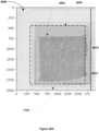
- One or more images of the biological sample on the substrate is obtained.
- Each of the one or more images comprises a corresponding plurality of pixels in the form of an array of pixel values.
- the array of pixel values comprises at least a least 100, 10,000, 100,000, 1 x 10 6 , 2 x 10 6 , 3 x 10 6 , 5 x 10 6 , 8 x 10 6 , 10 x 10 6 , or 15 x 10 6 pixel values.
- the one or more images are acquired using transmission light microscopy.
- the one or more images are acquired using fluorescent microscopy.
- a plurality of sequence reads, in electronic form, is obtained from the set of capture spots after the A) placing.
- the plurality of fiducial markers is used to provide a corresponding composite representation comprising (i) the respective image aligned to the set of capture spots on the substrate and (ii) a representation of each subset of sequence reads at the respective position within the respective image that maps to the corresponding capture spot on the substrate.
- the respective composite representation for an image in the one or more images provides a relative abundance of nucleic acid fragments mapping to each gene in a plurality of genes at each capture spot in the plurality of capture spots.
- the alignment algorithm is a local alignment that aligns the respective sequence read to a reference sequence using a scoring system that (i) penalizes a mismatch between a nucleotide in the respective sequence read and a corresponding nucleotide in the reference sequence in accordance with a substitution matrix and (ii) penalizes a gap introduced into an alignment of the sequence read and the reference sequence.
- the local alignment is a Smith-Waterman alignment.
- the reference sequence is all or portion of a reference genome.
- the one or more sequence reads that do not overlay any loci in the plurality of loci are removed from the plurality of sequence reads.
- the plurality of sequence reads for a given image are RNA-sequence reads and the removing comprises removing one or more sequences reads in the plurality of sequence reads that overlap a splice site in the reference sequence.
- the plurality of loci include one or more loci on a first chromosome and one or more loci on a second chromosome other than the first chromosome.
- each corresponding aggregated score is a class in a set of classes comprising obvious first class, likely first class, likely second class, and obvious second class.
- the first attribute is a first level of brightness or opacity and the second attribute is a second level of brightness or opacity.
- each respective representation of a capture spot in the plurality of capture spots in the composite representation is assigned the first attribute or the second attribute based upon the assignment of pixels in the vicinity of the respective representation of the capture spot in the composite representation.
- each respective capture probe plurality in the set of capture probe pluralities includes 1000 or more capture probes, 2000 or more capture probes, 10,000 or more capture probes, 100,000 or more capture probes, 1 x 10 6 or more capture probes, 2 x 10 6 or more capture probes, or 5 x 10 6 or more capture probes.
- the one or more analytes is a plurality of analytes
- a respective capture spot in the set of capture spots includes a plurality of capture probes
- each capture probe in the plurality of capture probes includes a capture domain that is characterized by a single capture domain type configured to bind to each analyte in the plurality of analytes in an unbiased manner.
- each respective capture spot in the set of capture spots is contained within a 100 micron by 100 micron square on the substrate. In some embodiments, each respective capture spot in the set of capture spots is contained within a 50 micron by 50 micron square on the substrate. In some embodiments, each respective capture spot in the set of capture spots is contained within a 10 micron by 10 micron square on the substrate. In some embodiments, each respective capture spot in the set of capture spots is contained within a 1 micron by 1 micron square on the substrate. In some embodiments, each respective capture spot in the set of capture spots is contained within a 500 nanometer by 500 nanometer square on the substrate. In some embodiments, each respective capture spot in the set of capture spots is contained within a 300 nanometer by 300 nanometer square on the substrate. In some embodiments, each respective capture spot in the set of capture spots is contained within a 200 nanometer by 200 nanometer square on the substrate.
- a distance between a center of each respective capture spot to a neighboring capture spot in the set of capture spots on the substrate is between 40 microns and 100 microns, between 300 nanometers and 15 microns, between 400 nanometers and 10 microns, between 500 nanometers and 8 microns, between 600 nanometers and 6 microns, between 700 nanometers and 5 microns, or between 800 nanometers and 4 microns.
- the plurality of heuristic classifiers comprises a third heuristic classifier that performs edge detection on the plurality of pixels to form a plurality of edges in the image, morphologically closes the plurality of edges to form a plurality of morphologically closed regions in the image and assigns pixels in the morphologically closed regions to the first class and pixels outside the morphologically closed regions to the second class, thereby causing the third heuristic classifier to cast a vote for each respective pixel in the plurality of pixels for either the first class or the second class.
- the obtaining the sequence reads comprises in-situ sequencing of the set of capture spots on the substrate. In some embodiments, the obtaining the sequence reads comprises high throughput sequencing of the set of capture spots on the substrate.
- a respective plurality of sequence reads include 3'-end or 5'-end paired sequence reads.
- Another aspect of the present disclosure provides a computer system comprising one or more processors, and memory.
- One or more programs are stored in the memory and are configured to be executed by the one or more processors. It will be appreciated that this memory can be on a single computer, a network of computers, one or more virtual machines, or in a cloud computing architecture.
- the one or more programs are for spatial analysis of analytes.
- Another aspect of the present disclosure provides a computing system including one or more processors and memory storing one or more programs for spatial nucleic analysis. It will be appreciated that this memory can be on a single computer, a network of computers, one or more virtual machines, or in a cloud computing architecture.
- the one or more programs are configured for execution by the one or more processors.
- the one or more programs include instructions for performing any of the methods disclosed above.
- Tissues and cells can be obtained from any source.
- tissues and cells can be obtained from single-cell or multicellular organisms ( e.g ., a mammal).
- Tissues and cells obtained from a mammal e.g ., a human
- analyte levels e.g ., gene and/or protein expression
- the position of a cell or subset of cells (e.g ., neighboring cells and/or non-neighboring cells) within a tissue can affect, for example, the cell's fate, behavior, morphology, signaling and cross-talk with other cells in the tissue.
- Differences in analyte levels within different cells in a tissue of a mammal can also provide information on different mechanisms of disease pathogenesis in a tissue and mechanism of action of a therapeutic treatment within a tissue. Differences in analyte levels within different cells in a tissue of a mammal can also provide information on the drug resistance mechanisms and the development of the same in a tissue of a mammal. Differences in the presence or absence of analytes within difference cells in a tissue of a multicellular organism ( e.g ., a mammal) can provide information on drug resistance mechanisms and the development of the same in a tissue of a multicellular organism.
- Capture probes can be, e.g ., attached to a surface, e.g ., a solid array, a bead, or a coverslip. In some examples, capture probes are not attached to a surface. In some examples, capture probes are encapsulated within, embedded within, or layered on a surface of a permeable composition ( e.g. , any of the substrates described herein). For example, capture probes can be encapsulated or disposed within a permeable bead ( e.g. , a gel bead). In some examples, capture probes are encapsulated within, embedded within, or layered on a surface of a substrate ( e.g. , any of the exemplary substrates described herein, such as a hydrogel or a porous membrane).
- a nucleic acid can contain nucleotides having any of a variety of analogs of these sugar moieties that are known in the art.
- a nucleic acid can include native or non-native nucleotides.
- a native deoxyribonucleic acid can have one or more bases selected from the group consisting of adenine (A), thymine (T), cytosine (C), or guanine (G)
- a ribonucleic acid can have one or more bases selected from the group consisting of uracil (U), adenine (A), cytosine (C), or guanine (G).
- Useful non-native bases that can be included in a nucleic acid or nucleotide are known in the art.
- a “probe” or a “target,” when used in reference to a nucleic acid or sequence of nucleic acids, is intended as a semantic identifier for the nucleic acid or sequence in the context of a method or composition, and does not limit the structure or function of the nucleic acid or sequence beyond what is expressly indicated.
- a "barcode” is a label, or identifier, that conveys or is capable of conveying information (e.g., information about an analyte in a sample, a bead, and/or a capture probe).
- a barcode can be part of an analyte, or independent of an analyte.
- a barcode can be attached to an analyte.
- a particular barcode can be unique relative to other barcodes.
- Barcodes can have a variety of different formats.
- barcodes can include non-random, semi-random, and/or random nucleic acid and/or amino acid sequences, and synthetic nucleic acid and/or amino acid sequences.
- Barcodes can spatially-resolve molecular components found in biological samples, for example, at single-cell resolution (e.g., a barcode can be or can include a "spatial barcode").
- a barcode includes both a UMI and a spatial barcode.
- a barcode includes two or more sub-barcodes that together function as a single barcode.
- a barcode includes both a UMI and a spatial barcode.
- a barcode includes two or more sub-barcodes that together function as a single barcode (e.g., a polynucleotide barcode).
- a polynucleotide barcode can include two or more polynucleotide sequences (e.g., sub-barcodes) that are separated by one or more non-barcode sequences.
- a “capture spot” (alternately, “feature” or “capture probe plurality”) is used herein to describe an entity that acts as a support or repository for various molecular entities used in sample analysis.
- capture spots include, but are not limited to, a bead, a spot of any two- or three-dimensional geometry (e.g., an ink jet spot, a masked spot, a square on a grid), a well, and a hydrogel pad.
- a capture spot is an area on a substrate at which capture probes labelled with spatial barcodes are clustered. Specific non-limiting embodiments of capture spots and substrates are further described below in the present disclosure.
- a “genome” generally refers to genomic information from a subject, which can be, for example, at least a portion of, or the entirety of, the subject's gene-encoded hereditary information.
- a genome can include coding regions ( e.g ., that code for proteins) as well as non-coding regions.
- a genome can include the sequences of some or all of the subject's chromosomes. For example, the human genome ordinarily has a total of 46 chromosomes. The sequences of some or all of these can constitute the genome.
- an “adaptor,” an “adapter,” and a “tag” are terms that are used interchangeably in this disclosure, and refer to species that can be coupled to a polynucleotide sequence (in a process referred to as "tagging") using any one of many different techniques including (but not limited to) ligation, hybridization, and tagmentation.
- Adaptors can also be nucleic acid sequences that add a function, e.g. , spacer sequences, primer sequences/sites, barcode sequences, unique molecular identifier sequences.
- Small RNAs mainly include 5.8S ribosomal RNA (rRNA), 5S rRNA, transfer RNA (tRNA), microRNA (miRNA), small interfering RNA (siRNA), small nucleolar RNA (snoRNAs), Piwi-interacting RNA (piRNA), tRNA-derived small RNA (tsRNA), and small rDNA-derived RNA (srRNA).
- the RNA can be double-stranded RNA or single-stranded RNA.
- the RNA can be circular RNA.
- the RNA can be a bacterial rRNA ( e.g ., 16s rRNA or 23s rRNA).
- a perturbation agent e.g ., a CRISPR crRNA/sgRNA, TALEN, zinc finger nuclease, and/or antisense oligonucleotide as described herein.
- a perturbation agent is a small molecule, an antibody, a drug, an aptamer, a miRNA, a physical environmental (e.g ., temperature change), or any other known perturbation agents.
- Analytes can include a nucleic acid molecule with a nucleic acid sequence encoding at least a portion of a V(D)J sequence of an immune cell receptor (e.g ., a TCR or BCR).
- the nucleic acid molecule is cDNA first generated from reverse transcription of the corresponding mRNA, using a poly(T) containing primer. The generated cDNA can then be barcoded using a capture probe, featuring a barcode sequence (and optionally, a UMI sequence) that hybridizes with at least a portion of the generated cDNA.
- Biological samples can also include fetal cells.
- a procedure such as amniocentesis can be performed to obtain a fetal cell sample from maternal circulation.
- Sequencing of fetal cells can be used to identify any of a number of genetic disorders, including, e.g ., aneuploidy such as Down's syndrome, Edwards syndrome, and Patau syndrome.
- cell surface features of fetal cells can be used to identify any of a number of disorders or diseases.
- a biological sample can be harvested from a subject (e.g., via surgical biopsy, whole subject sectioning, grown in vitro on a growth substrate or culture dish as a population of cells, or prepared for analysis as a tissue slice or tissue section). Grown samples may be sufficiently thin for analysis without further processing steps. Alternatively, grown samples, and samples obtained via biopsy or sectioning, can be prepared as thin tissue sections using a mechanical cutting apparatus such as a vibrating blade microtome. As another alternative, in some embodiments, a thin tissue section can be prepared by applying a touch imprint of a biological sample to a suitable substrate material.
- the thickness of the tissue section can be a fraction of (e.g., less than 0.9, 0.8, 0.7, 0.6, 0.5, 0.4, 0.3, 0.2, or 0.1) the maximum cross-sectional dimension of a cell.
- tissue sections having a thickness that is larger than the maximum cross-section cell dimension can also be used.
- cryostat sections can be used, which can be, e.g., 10-20 micrometers thick.
- the thickness of a tissue section typically depends on the method used to prepare the section and the physical characteristics of the tissue, and therefore sections having a wide variety of different thicknesses can be prepared and used.
- the thickness of the tissue section can be at least 0.1, 0.2, 0.3, 0.4, 0.5, 0.7, 10, 15, 2, 3, 4, 5, 6, 7, 8, 9, 10, 11, 12, 13, 14, 15, 20, 30, 40, or 50 micrometers.
- Thicker sections can also be used if desired or convenient, e.g ., at least 70, 80, 90, or 100 micrometers or more.
- the thickness of a tissue section is between 1-100 micrometers, 1-50 micrometers, 1-30 micrometers, 1-25 micrometers, 1-20 micrometers, 1-15 micrometers, 1-10 micrometers, 2-8 micrometers, 3-7 micrometers, or 4-6 micrometers, but as mentioned above, sections with thicknesses larger or smaller than these ranges can also be analysed.
- Multiple sections can also be obtained from a single biological sample.
- multiple tissue sections can be obtained from a surgical biopsy sample by performing serial sectioning of the biopsy sample using a sectioning blade. Spatial information among the serial sections can be preserved in this manner, and the sections can be analysed successively to obtain three-dimensional information about the biological sample.
- the frozen tissue sample can be sectioned, e.g ., thinly sliced, onto a substrate surface using any number of suitable methods.
- a tissue sample can be prepared using a chilled microtome (e.g.
- the biological sample can be prepared using formalin-fixation and paraffin-embedding (FFPE), which are established methods.
- FFPE formalin-fixation and paraffin-embedding
- cell suspensions and other non-tissue samples can be prepared using formalin-fixation and paraffin-embedding.
- the sample can be sectioned as described above.
- the paraffin-embedding material can be removed from the tissue section (e.g ., deparaffinization) by incubating the tissue section in an appropriate solvent (e.g ., xylene) followed by a rinse ( e.g ., 99.5% ethanol for 2 minutes, 96% ethanol for 2 minutes, and 70% ethanol for 2 minutes).
- acetone fixation is used with fresh frozen samples, which can include, but are not limited to, cortex tissue, mouse olfactory bulb, human brain tumor, human post-mortem brain, and breast cancer samples.
- a compatible fixation method is chosen and/or optimized based on a desired workflow. For example, formaldehyde fixation may be chosen as compatible for workflows using IHC/IF protocols for protein visualization. As another example, methanol fixation may be chosen for workflows emphasizing RNA/DNA library quality.
- Acetone fixation may be chosen in some applications to permeabilize the tissue.When acetone fixation is performed, pre- permeabilization steps (described below) may not be performed. Alternatively, acetone fixation can be performed in conjunction with permeabilization steps.
- a biological sample can be embedded in any of a variety of other embedding materials to provide a substrate to the sample prior to sectioning and other handling steps.
- the embedding material is removed prior to analysis of tissue sections obtained from the sample.
- suitable embedding materials include, but are not limited to, waxes, resins ( e.g. , methacrylate resins), epoxies, and agar.
- the sample is stained using a detectable label (e.g. , radioisotopes, fluorophores, chemiluminescent compounds, bioluminescent compounds, and dyes) as described elsewhere herein.
- a biological sample is stained using only one type of stain or one technique.
- staining includes biological staining techniques such as H&E staining.
- staining includes identifying analytes using fluorescently-conjugated antibodies.
- a biological sample is stained using two or more different types of stains, or two or more different staining techniques.
- a biological sample can be prepared by staining and imaging using one technique (e.g. , H&E staining and brightfield imaging), followed by staining and imaging using another technique (e.g ., IHC/IF staining and fluorescence microscopy) for the same biological sample.
- a hydrogel can swell in the presence of water.
- a hydrogel comprises a natural material.
- a hydrogel includes a synthetic material.
- a hydrogel includes a hybrid material, e.g ., the hydrogel material comprises elements of both synthetic and natural polymers. Any of the materials used in hydrogels or hydrogels comprising a polypeptide-based material described herein can be used.
- Embedding the sample in this manner typically involves contacting the biological sample with a hydrogel such that the biological sample becomes surrounded by the hydrogel.
- the sample can be embedded by contacting the sample with a suitable polymer material, and activating the polymer material to form a hydrogel.
- the hydrogel is formed such that the hydrogel is internalized within the biological sample.
- hydrogel-matrix to a biological sample typically depends on the nature and preparation of the biological sample (e.g ., sectioned, non-sectioned, fresh-frozen, type of fixation).
- a hydrogel can be any appropriate hydrogel where upon formation of the hydrogel on the biological sample the biological sample becomes anchored to or embedded in the hydrogel.
- Non-limiting examples of hydrogels are described herein or are known in the art.
- the hydrogel can include a monomer solution and an ammonium persulfate (APS) initiator / tetramethylethylenediamine (TEMED) accelerator solution.
- APS ammonium persulfate
- TEMED tetramethylethylenediamine
- a biological sample immobilized on a substrate e.g ., a biological sample prepared using methanol fixation or formalin-fixation and paraffin-embedding (FFPE)
- FFPE formalin-fixation and paraffin-embedding
- a hydrogel is formed on top of a biological sample on a substrate (e.g. , glass slide).
- hydrogel formation can occur in a manner sufficient to anchor ( e.g ., embed) the biological sample to the hydrogel.
- the biological sample is anchored to ( e.g ., embedded in) the hydrogel where separating the hydrogel from the substrate results in the biological sample separating from the substrate along with the hydrogel.
- a hydrogel includes a linker that allows anchoring of the biological sample to the hydrogel.
- a hydrogel includes linkers that allow anchoring of biological analytes to the hydrogel. In such cases, the linker can be added to the hydrogel before, contemporaneously with, or after hydrogel formation.
- a biological sample embedded in a hydrogel can be isometrically expanded.
- Isometric expansion methods that can be used include hydration, a preparative step in expansion microscopy, as described in Chen et al., 2015, Science 347(6221) 543-548 , Asano et al., 2018, Current Protocols 80:1, doi:10.1002/cpcb.56 ; Gao et al., 2017, BMC Biology 15:50, doi:10.1186/s12915-017-0393-3 , and Wassie et al, 2018, Expansion microscopy: principles and uses in biological research, Nature Methods 16(1): 33-41 , each of which is incorporated by reference in its entirety.
- the steps used to perform isometric expansion of the biological sample can depend on the characteristics of the sample (e.g. , thickness of tissue section, fixation, cross-linking), and/or the analyte of interest (e.g ., different conditions to anchor RNA, DNA, and protein to a gel).
- characteristics of the sample e.g. , thickness of tissue section, fixation, cross-linking
- analyte of interest e.g ., different conditions to anchor RNA, DNA, and protein to a gel.
- Isometric expansion can be performed by anchoring one or more components of a biological sample to a gel, followed by gel formation, proteolysis, and swelling. Isometric expansion of the biological sample can occur prior to immobilization of the biological sample on a substrate, or after the biological sample is immobilized to a substrate. In some embodiments, the isometrically expanded biological sample can be removed from the substrate prior to contacting expanded biological sample with a spatially barcoded array (e.g., spatially barcoded capture probes on a substrate).
- a spatially barcoded array e.g., spatially barcoded capture probes on a substrate.
- proteins in the biological sample are anchored to a swellable gel such as a polyelectrolyte gel.
- An antibody can be directed to the protein before, after, or in conjunction with being anchored to the swellable gel.
- DNA and/or RNA in a biological sample can also be anchored to the swellable gel via a suitable linker.
- linkers include, but are not limited to, 6-((Acryloyl)amino) hexanoic acid (Acryloyl-X SE) (available from ThermoFisher, Waltham, MA), Label-IT Amine (available from MirusBio, Madison, WI) and Label X (described for example in Chen et al., Nat. Methods 13:679-684, 2016 , the entire contents of which are incorporated herein by reference).
- Isometric expansion of the sample can increase the spatial resolution of the subsequent analysis of the sample.
- isometric expansion of the biological sample can result in increased resolution in spatial profiling (e.g., single-cell profiling).
- the increased resolution in spatial profiling can be determined by comparison of an isometrically expanded sample with a sample that has not been isometrically expanded.
- a biological sample is isometrically expanded to a volume at least 2x, 2.1x, 2.2x, 2.3x, 2.4x, 2.5x, 2.6x, 2.7x, 2.8x, 2.9x, 3x, 3.1x, 3.2x, 3.3x, 3.4x, 3.5x, 3.6x, 3.7x, 3.8x, 3.9x, 4x, 4.1x, 4.2x, 4.3x, 4.4x, 4.5x, 4.6x, 4.7x, 4.8x, or 4.9x its non-expanded volume.
- the sample is isometrically expanded to at least 2x and less than 20x of its non-expanded volume.
- a biological sample embedded in a hydrogel is isometrically expanded to a volume at least 2x, 2.1x, 2.2x, 2.3x, 2.4x, 2.5x, 2.6x, 2.7x, 2.8x, 2.9x, 3x, 3.1x, 3.2x, 3.3x, 3.4x, 3.5x, 3.6x, 3.7x, 3.8x, 3.9x, 4x, 4.1x, 4.2x, 4.3x, 4.4x, 4.5x, 4.6x, 4.7x, 4.8x, or 4.9x its non-expanded volume.
- the biological sample embedded in a hydrogel is isometrically expanded to at least 2x and less than 20x of its non-expanded volume.
- the biological sample can be attached to a substrate (e.g ., a chip).
- a substrate e.g ., a chip
- Attachment of the biological sample can be irreversible or reversible, depending upon the nature of the sample and subsequent steps in the analytical method.
- the sample can be attached to the substrate reversibly by applying a suitable polymer coating to the substrate, and contacting the sample to the polymer coating.
- the sample can then be detached from the substrate using an organic solvent that at least partially dissolves the polymer coating.
- Hydrogels are examples of polymers that are suitable for this purpose.
- the cells are distributed onto the substrate such that at least one cell occupies a distinct spatial feature on the substrate.
- the cells can be immobilized on the substrate ( e.g ., to prevent lateral diffusion of the cells).
- a cell immobilization agent can be used to immobilize a non-aggregated or disaggregated sample on a spatially-barcoded array prior to analyte capture.
- a "cell immobilization agent" can refer to an antibody, attached to a substrate, which can bind to a cell surface marker.
- the distribution of the plurality of cells on the substrate follows Poisson statistics.
- a biological sample can be permeabilized by exposing the sample to one or more permeabilizing agents.
- Suitable agents for this purpose include, but are not limited to, organic solvents (e.g ., acetone, ethanol, and methanol), cross-linking agents (e.g., paraformaldehyde), detergents (e.g ., saponin, Triton X-100 TM , Tween-20 TM , or sodium dodecyl sulfate (SDS)), and enzymes (e.g ., trypsin, proteases (e.g ., proteinase K).
- organic solvents e.g ., acetone, ethanol, and methanol
- cross-linking agents e.g., paraformaldehyde
- detergents e.g ., saponin, Triton X-100 TM , Tween-20 TM , or sodium dodecyl sulfate (SDS)
- a biological sample can be permeabilized by exposing the sample to greater than about 10 w/v % (e.g., greater than about 20 w/v %, greater than about 30 w/v %, greater than about 40 w/v%, greater than about 50 w/v %, greater than about 6.0 w/v %, greater than about 7.0 w/v %, greater than about 8.0 w/v %, greater than about 9.0 w/v %, greater than about 10.0 w/v %, greater than about 11.0 w/v %, greater than about 12.0 w/v %, or greater than about 13.0 w/v %) sodium dodecyl sulfate (SDS) and/or N-lauroylsarcosine or N-lauroylsarcosine sodium salt.
- SDS sodium dodecyl sulfate
- a biological sample can be permeabilized by exposing the sample (e.g., for about 5 minutes to about 1 hour, about 5 minutes to about 40 minutes, about 5 minutes to about 30 minutes, about 5 minutes to about 20 minutes, or about 5 minutes to about 10 minutes) to about 10 w/v % to about 14.0 w/v % (e.g., about 20 w/v % to about 14.0 w/v %, about 2.0 w/v % to about 12.0 w/v %, about 2.0 w/v % to about 10.0 w/v %, about 4.0 w/v % to about 14.0 w/v %, about 4.0 w/v % to about 12.0 w/v %, about 4.0 w/v % to about 10.0 w/v %, about 6.0 w/v % to about 14.0 w/v %, about 6.0 w/v % to about 12.0 w/v %, about 6.0 w/v % to
- a medium, solution, or permeabilization solution may contain one or more proteases.
- a biological sample treated with a protease capable of degrading histone proteins can result in the generation of fragmented genomic DNA.
- the fragmented genomic DNA can be captured using the same capture domain (e.g ., capture domain having a poly(T) sequence) used to capture mRNA.
- a biological sample is treated with a protease capable of degrading histone proteins and an RNA protectant prior to spatial profiling in order to facilitate the capture of both genomic DNA and mRNA.
- a biological sample is permeabilized by exposing the sample to a protease capable of degrading histone proteins.
- histone protein typically refers to a linker histone protein (e.g., H1) and/or a core histone protein ( e.g ., H2A, H2B, H3, and H4).
- a protease degrades linker histone proteins, core histone proteins, or linker histone proteins and core histone proteins. Any suitable protease capable of degrading histone proteins in a biological sample can be used.
- a trypsin enzyme is P00761, P00760, Q29463, or a combination thereof.
- a protease capable of degrading one or more histone proteins comprises an amino acid sequence with at least 80% sequence identity to P00761, P00760, or Q29463.
- a protease capable of degrading one or more histone proteins comprises an amino acid sequence with at least 85%, 90%, 91%, 92%, 93%, 94%, 95%, 96%, 97%, 98%, or 99% identity to P00761, P00760, or Q29463.
- a protease may be considered a functional variant if it has at least 50% e.g ., at least 60%, 70%, 80%, 90%, 95%, 96%, 97%, 98%, 99%, or 100% of the activity relative to the activity of the protease in condition optimum for the enzyme.
- the enzymatic treatment with pepsin enzyme, or pepsin like enzyme can include: P03954/PEPA1_MACFU; P28712/PEPA1_RABIT; P27677/PEPA2_MACFU; P27821/PEPA2_RABIT; P0DJD8/PEPA3_HUMAN; P27822/PEPA3_RABIT; P0DJD7/PEPA4_HUMAN; P27678/PEPA4_MACFU; P28713/PEPA4_RABIT; P0DJD9/PEPA5_HUMAN; Q9D106/PEPA5_MOUSE; P27823/PEPAF_RABIT; P00792/PEPA_BOVIN; Q9N2D4/PEPA_CALJA; Q9GMY6/PEPA_CANLF; P00793/PEPA_CHICK; P11489/PEPA_MACMU; P00791/PEPA_PIG; Q9GMY7/PEPA_RHIFE; Q9
- the protease may be contained in a reaction mixture (solution), which also includes other components (e.g ., buffer, salt, chelator (e.g ., EDTA), and/or detergent (e.g ., SDS, N-Lauroylsarcosine sodium salt solution)).
- the reaction mixture may be buffered, having a pH of about 6.5-8.5, e.g ., about 7.0-8.0.
- the RNA protectant includes a salt.
- the salt may include ammonium sulfate, ammonium bisulfate, ammonium chloride, ammonium acetate, cesium sulfate, cadmium sulfate, cesium iron (II) sulfate, chromium (III) sulfate, cobalt (II) sulfate, copper (II) sulfate, lithium chloride, lithium acetate, lithium sulfate, magnesium sulfate, magnesium chloride, manganese sulfate, manganese chloride, potassium chloride, potassium sulfate, sodium chloride, sodium acetate, sodium sulfate, zinc chloride, zinc acetate and zinc sulfate.
- the salt may be present at a concentration of about 20 g/100 ml of medium or less, such as about 15g/100 ml, 10g/100 ml, 9g/100 ml, 8g/100 ml, 7g/100 ml, 6g/100 ml, 5g/100 ml or less, e.g ., about 4g, 3g, 2g or 1g/100ml.
- a diffusion-resistant medium typically used to limit diffusion of analytes, can include at least one permeabilization reagent.
- the diffusion-resistant medium e.g ., a hydrogel
- the diffusion-resistant medium can include wells ( e.g ., micro-, nano-, or picowells or pores) containing a permeabilization buffer or reagents.
- the diffusion-resistant medium e.g ., a hydrogel
- the hydrogel or other diffusion-resistant medium can contain dried reagents or monomers to deliver permeabilization reagents when the diffusion-resistant medium is applied to a biological sample.
- the diffusion-resistant medium, e.g ., hydrogel
- the diffusion-resistant medium, is covalently attached to a solid substrate (e.g ., an acrylated glass slide).
- the analytes then diffuse into the spatially-barcoded hydrogel after exposure to permeabilization reagents.
- the spatially-barcoded hydrogel e.g. , porous membrane
- biological analytes diffuse into the hydrogel before exposure to permeabilization reagents (e.g. , when secreted analytes are present outside of the biological sample or in instances where a biological sample is lysed or permeabilized by other means prior to addition of permeabilization reagents).
- the diffusion-resistant medium e.g ., hydrogel
- the diffusion-resistant medium is between approximately 50-500 micrometers thick including 500, 450, 400, 350, 300, 250, 200, 150, 100, or 50 micrometers thick, or any thickness within 50 and 500 micrometers.
- biological samples can be processed to selectively release an analyte from a subcellular region of a cell according to established methods.
- a method provided herein can include detecting at least one biological analyte present in a subcellular region of a cell in a biological sample.
- a "subcellular region" can refer to any subcellular region.
- a subcellular region can refer to cytosol, a mitochondria, a nucleus, a nucleolus, an endoplasmic reticulum, a lysosome, a vesicle, a Golgi apparatus, a plastid, a vacuole, a ribosome, cytoskeleton, or combinations thereof.
- a biological analyte can be selectively released from a subcellular region of a cell by selective permeabilization or selective lysing.
- selective permeabilization can refer to a permeabilization method that can permeabilize a membrane of a subcellular region while leaving a different subcellular region substantially intact ( e.g ., biological analytes are not released from subcellular region due to the applied permeabilization method).
- selective permeabilization methods include using electrophoresis and/or applying a permeabilization reagent.
- selective lysing can refer to a lysis method that can lyse a membrane of a subcellular region while leaving a different subcellular region substantially intact (e.g ., biological analytes are not released from subcellular region due to the applied lysis method).
- a lysis method that can lyse a membrane of a subcellular region while leaving a different subcellular region substantially intact (e.g ., biological analytes are not released from subcellular region due to the applied lysis method).
- Several methods for selective permeabilization or lysis are known to one of skill in the art including the methods described in Lu et al. Lab Chip. 2005 Jan;5(1):23-9 ; Niklas et al., 2011, Anal Biochem 416(2):218-27 ; Cox and Emili., 2006, Nat Protoc. 1(4):1872-8 ; Chiang et al., 2000, J Biochem. Biophys. Methods. 20;46(1-2):53-68 ; and Yamauchi and
- one or more primer sequences with sequence complementarity to one or more RNAs of interest can be used to amplify the one or more RNAs of interest, thereby selectively enriching these RNAs.
- an oligonucleotide with sequence complementarity to the complementary strand of captured RNA e.g ., cDNA
- cDNA can bind to the cDNA.
- biotinylated oligonucleotides with sequence complementary to one or more cDNAs of interest binds to the cDNA and can be selected using biotinylation-streptavidin affinity using any of a variety of methods known to the field ( e.g ., streptavidin beads).
- RNA e.g ., ribosomal and/or mitochondrial RNA
- RNA can be down-selected (e.g ., removed, depleted) using any of a variety of methods.
- Non-limiting examples of a hybridization and capture method of ribosomal RNA depletion include RiboMinus TM , RiboCop TM , and Ribo-Zero TM .
- Another non-limiting RNA depletion method involves hybridization of complementary DNA oligonucleotides to unwanted RNA followed by degradation of the RNA/DNA hybrids using RNase H.
- Non-limiting examples of a hybridization and degradation method include NEBNext ® rRNA depletion, NuGEN AnyDeplete, or RiboZero Plus.
- Another non-limiting ribosomal RNA depletion method includes ZapR TM digestion, for example SMARTer.
- SMARTer method random nucleic acid adapters are hybridized to RNA for first-strand synthesis and tailing by reverse transcriptase, followed by template switching and extension by reverse transcriptase. Additionally, first round PCR amplification adds full-length Illumina sequencing adapters (e.g., Illumina indexes). Ribosomal RNA is cleaved by ZapR v2 and R probes v2.
- a second round of PCR is performed, amplifying non-rRNA molecules (e.g., cDNA).
- ribosomal depletion protocols/kits can be further combined with the methods described herein to optimize protocols for a specific biological sample.
- probes can be administered to a sample that selectively hybridize to ribosomal RNA (rRNA), thereby reducing the pool and concentration of rRNA in the sample.
- Probes can be administered to a biological sample that selectively hybridize to mitochondria RNA (mtRNA), thereby reducing the pool and concentration of mtRNA in the sample.
- mtRNA mitochondria RNA
- probes complementary to mitochondrial RNA can be added during cDNA synthesis, or probes complementary to both ribosomal and mitochondrial RNA can be added during cDNA synthesis. Subsequent application of capture probes to the sample can result in improved capture of other types of RNA due to a reduction in non-specific RNA (e.g. down-selected RNA) present in the sample.
- hematoxylin from an H&E stain, can be optionally removed from the biological sample by washing in dilute HCl (0.001M to 0.1M) prior to further processing.
- pepsin can be dissolved in dilute HCl (0.001M to 0.1M) prior to further processing.
- biological samples can be washed additional times (e.g ., 2, 3, 4, 5, or more times) in dilute HCl prior to incubation with a protease (e.g ., pepsin), but after proteinase K treatment.
- the sample can be treated with one or more enzymes.
- one or more endonucleases to fragment DNA DNA polymerase enzymes, and dNTPs used to amplify nucleic acids can be added.
- Other enzymes that can also be added to the sample include, but are not limited to, polymerase, transposase, ligase, and DNAse, and RNAse.
- reverse transcriptase enzymes can be added to the sample, including enzymes with terminal transferase activity, primers, and template switch oligonucleotides (TSOs).
- Template switching can be used to increase the length of a cDNA, e.g ., by appending a predefined nucleic acid sequence to the cDNA. Such a step of reverse transcription is illustrated in FIG. 37 .
- the appended nucleic acid sequence comprises one or more ribonucleotides.
- carrier RNA can be added immediately prior to a second strand cDNA synthesis on oligonucleotides released from an array. In some embodiments, carrier RNA can be added immediately prior to a post in vitro transcription clean-up step. In some embodiments, carrier RNA can be added prior to amplified RNA purification and quantification. In some embodiments, carrier RNA can be added before RNA quantification. In some embodiments, carrier RNA can be added immediately prior to both a second strand cDNA synthesis and a post in vitro transcription clean-up step.
- analytes in a biological sample can be pre-processed prior to interaction with a capture probe.
- polymerization reactions catalyzed by a polymerase e.g., DNA polymerase or reverse transcriptase
- a primer for the polymerization reaction includes a functional group that enhances hybridization with the capture probe.
- the capture probes can include appropriate capture domains to capture biological analytes of interest (e.g., poly-dT sequence to capture poly(A) mRNA).
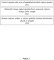
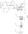
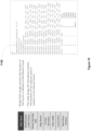
- This section of the disclosure describes methods, apparatus, systems, and compositions for spatial array-based analysis of biological samples.
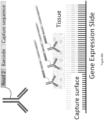
- Array-based spatial analysis methods involve the transfer of one or more analytes from a biological sample to an array of capture spots on a substrate, each of which is associated with a unique spatial location on the array. Subsequent analysis of the transferred analytes includes determining the identity of the analytes and the spatial location of each analyte within the sample. The spatial location of each analyte within the sample is determined based on the capture spot to which each analyte is bound in the array, and the capture spot's relative spatial location within the array.
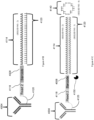
- FIG. 2 depicts an exemplary embodiment of this general method, the spatially-barcoded array populated with capture probes (as described further herein) can be contacted with a sample 201.
- the spatially-barcoded capture probes are cleaved and then interact with cells within the provided sample 202.
- the interaction can be a covalent or non-covalent cell-surface interaction.
- the interaction can be an intracellular interaction facilitated by a delivery system or a cell penetration peptide.
- the sample can be optionally removed for analysis.
- the sample can be optionally dissociated before analysis.
- the capture probes can be analyzed to obtain spatially-resolved information about the tagged cell 203.
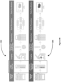
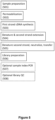
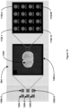
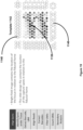
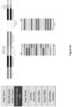
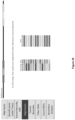
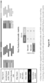
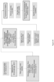
- FIGS. 3A and 3B show exemplary workflows that include preparing a sample on a spatially-barcoded array 301.
- Sample preparation may include placing the sample on a substrate ( e.g ., chip, slide, etc .), fixing the sample, and/or staining the sample for imaging.
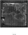
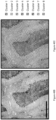
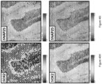
- the sample stained or not stained is then imaged on the array 302 using brightfield (to image the sample, e.g ., using a hematoxylin and eosin stain) or fluorescence (to image capture spots) as illustrated in the upper panel 302 of FIG. 3B ) and/or emission imaging modalities (as illustrated in the lower panel 304 of FIG. 3B ).
- Brightfield images are transmission microscopy images where broad-spectrum, white light is placed on one side of the sample mounted on a substrate and the camera objective is placed on the other side and the sample itself filters the light in order to generate colors or grayscale intensity images 1124, akin to a stained glass window viewed from inside on a bright day.
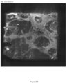
- emission imaging such as fluorescence imaging is used.
- emission imaging approaches the sample on the substrate is exposed to light of a specific narrow band (first wavelength band) of light and then the light that is re-emitted from the sample at a slightly different wavelength (second wavelength band) is measured.
- first wavelength band a specific narrow band
- second wavelength band a slightly different wavelength
- This absorption and re-emission is due to the presence of a fluorophore that is sensitive to the excitation used and can be either a natural property of the sample or an agent the sample has been exposed to in preparation for the imaging.
- an antibody that binds to a certain protein or class of proteins, and that is labeled with a certain fluorophore is added to the sample.
- the locations on the sample that include the protein or class of proteins will emit the second wavelength band.
- multiple antibodies with multiple fluorophores can be used to label multiple proteins in the sample.
- Each such fluorophore requires excitation with a different wavelength of light and further emits a different unique wavelength of light.
- the sample is subjected to the different wavelengths of light that will excite the multiple fluorophores on a serial basis and images for each of these light exposures is saved as an image thus generating a plurality of images.
- the image is subjected to a first wavelength that excites a first fluorophore to emit at a second wavelength and a first image of the sample is taken while the sample is being exposed to the first wavelength. Then the exposure of the sample to the first wavelength is discontinued and the sample is exposed to a third wavelength (different from the first wavelength) that excites a second fluorophore at a fourth wavelength (different from the second wavelength) and a second image of the sample is taken while the sample is being exposed to the third wavelength.
- a third wavelength different from the first wavelength
- a fourth wavelength different from the second wavelength
- a series of images of the tissue each depicting the spatial arrangement of some different parameter such as a particular protein or protein class, is obtained.
- more than one fluorophore is imaged at the same time. In such an approach a combination of excitation wavelengths are used, each for one of the more than one fluorophore, and a single image is collected.
- each of the images collected through emission imaging is gray scaled.
- each of the images are assigned a color (shades of red, shades of blue, etc .) and combined into one composite color image for viewing.
- fluorescence imaging allows for the spatial analysis of protein abundance (e.g ., spatial proteomics) in the sample.
- spatial abundance is analyzed on its own.
- such spatial abundance is analyzed together with transcriptomics.
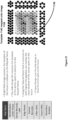
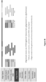
- permeabilization reagents may be administered to the sample via a diffusion-resistant medium and/or a physical barrier such as a lid, where the sample is sandwiched between the diffusion-resistant medium and/or barrier and the array-containing substrate.
- the analytes are migrated toward the spatially-barcoded capture array using any number of techniques disclosed herein.
- analyte migration can occur using a diffusion-resistant medium lid and passive migration.
- analyte migration can be active migration, using an electrophoretic transfer system, for example.
- the capture probes can hybridize or otherwise bind a target analyte 403.
- the sample can be optionally removed from the array 404.
- the original mRNA template and template switching oligonucleotide can then be denatured from the cDNA and the spatially-barcoded capture probe can then hybridize with the cDNA and a complement of the cDNA can be generated.
- the first strand cDNA can then be purified and collected for downstream amplification steps.
- the first strand cDNA can be optionally amplified using PCR 406, where the forward and reverse primers flank the spatial barcode and target analyte regions of interest, generating a library associated with a particular spatial barcode 407.
- the library preparation can be quantified and/or subjected to quality control to verify the success of the library preparation steps 408.
- the cDNA comprises a sequencing by synthesis (SBS) primer sequence.
- the library amplicons are sequenced and analyzed to decode spatial information 407, with an additional library quality control (QC) step 408.
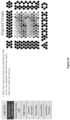
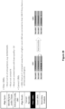
- the second strand cDNA is then denatured from the first strand cDNA, neutralized, and transferred to a tube 505.
- cDNA quantification and amplification can be performed using standard techniques discussed herein.
- the cDNA can then be subjected to library preparation 506 and indexing 507, including fragmentation, end-repair, and a-tailing, and indexing PCR steps.
- the library can also be optionally tested for quality control (QC) 508.
- Reverse transcription (RT) reagents can be added to permeabilized biological samples. Incubation with the RT reagents can produce spatially-barcoded full-length cDNA from the captured analytes (e.g ., polyadenylated mRNA). Second strand reagents (e.g ., second strand primers, enzymes) can be added to the biological sample on the slide to initiate second strand synthesis. The resulting cDNA can be denatured from the capture probe template and transferred ( e.g ., to a clean tube) for amplification, and/or library construction. The spatially-barcoded, full-length cDNA can be amplified via PCR prior to library construction.
- PCR Reverse transcription
- isothermal amplification can be faster than a standard PCR reaction.
- isothermal amplification can be linear amplification (e.g ., asymmetrical with a single primer), or exponential amplification ( e.g ., with two primers).
- isothermal nucleic acid amplification can be performed by a template-switching oligonucleotide primer.
- the template switching oligonucleotide adds a common sequence onto the 5' end of the RNA being reverse transcribed.
- a capture probe interacts with an analyte (e.g ., mRNA) and reverse transcription is performed such that additional nucleotides are added to the end of the cDNA creating a 3' overhang as described herein.
- analyte e.g ., mRNA
- reverse transcription is performed such that additional nucleotides are added to the end of the cDNA creating a 3' overhang as described herein.
- a template switching oligonucleotide hybridizes to untemplated poly(C) nucleotides added by a reverse transcriptase to continue replication to the 5' end of the template switching oligonucleotide, thereby generating full-length cDNA ready for further amplification.
- the template switching oligonucleotide adds a common 5' sequence to full-length cDNA that is used for cDNA amplification (e.g ., a reverse complement of the template switching oligonucleotide).
- the template switching oligonucleotide can serve as a primer in a cDNA amplification reaction (e.g ., with a DNA polymerase).
- double stranded cDNA e.g ., first strand cDNA and second strand reverse complement cDNA
- the strand displacing DNA polymerase can generate a displaced second strand resulting in an amplified product.
- the isothermal nucleic acid amplification is recombinase polymerase nucleic acid amplification.
- Recombinase polymerase nucleic acid amplification is described in Piepenburg et al., 2006, DNA Detection Using Recombinant Proteins, PLoS Biol. 4, 7 e204 and Li et.
- the sample can be rehydrated, blocked, and permeabilized (3XSSC, 2% BSA, 0.1% Triton X, 1 U/ ⁇ l RNAse inhibitor for 10 min at 4°C) before being stained with fluorescent primary antibodies (1:100 in 3XSSC, 2% BSA, 0.1% Triton X, 1 U/ ⁇ l RNAse inhibitor for 30 min at 4°C).
- the biological sample can be washed, coverslipped (in glycerol + 1 U/ ⁇ l RNAse inhibitor), imaged ( e.g ., using a confocal microscope or other apparatus capable of fluorescent detection), washed, and processed according to analyte capture or spatial workflows described herein.
- optimizing permeabilization can be useful for identifying intracellular analytes.
- Permeabilization optimization can include selection of permeabilization agents, concentration of permeabilization agents, and permeabilization duration. Tissue permeabilization is discussed elsewhere herein.
- blocking an array and/or a biological sample in preparation of labeling the biological sample decreases unspecific binding of the antibodies to the array and/or biological sample (decreases background).
- Some embodiments provide for blocking buffers/blocking solutions that can be applied before and/or during application of the label, where the blocking buffer can include a blocking agent, and optionally a surfactant and/or a salt solution.
- a blocking agent can be bovine serum albumin (BSA), serum, gelatin (e.g ., fish gelatin), milk ( e.g ., non-fat dry milk), casein, polyethylene glycol (PEG), polyvinyl alcohol (PVA), or polyvinylpyrrolidone (PVP), biotin blocking reagent, a peroxidase blocking reagent, levamisole, Carnoy's solution, glycine, lysine, sodium borohydride, pontamine sky blue, Sudan Black, trypan blue, FITC blocking agent, and/or acetic acid.
- the blocking buffer/blocking solution can be applied to the array and/or biological sample prior to and/or during labeling (e.g ., application of fluorophore-conjugated antibodies) to the biological sample.
- additional steps or optimizations can be included in performing IF/IHC protocols in conjunction with spatial arrays. Additional steps or optimizations can be included in performing spatially-tagged analyte capture agent workflows discussed herein.
- analyte e.g ., detecting the location of an analyte, e.g ., a biological analyte
- a biological sample e.g ., an analyte present in a biological sample, such as a tissue section
- a biological sample e.g ., an analyte present in a biological sample, such as a tissue section
- a biological sample e.g ., an analyte present in a biological sample, such as a tissue section
- a biological sample e.g ., an analyte present in a biological sample, such as a tissue section
- the rate of permeabilization is slowed prior to contacting a biological sample with an array (e.g ., to limit diffusion of analytes away from their original locations in the biological sample).
- modulating the rate of permeabilization e.g ., modulating the activity of a permeabilization reagent
- modulating the rate of permeabilization can occur by modulating a condition that the biological sample is exposed to (e.g ., modulating temperature, pH, and/or light).
- modulating the rate of permeabilization includes use of external stimuli (e.g ., small molecules, enzymes, and/or activating reagents) to modulate the rate of permeabilization.
- analyte e.g ., detecting the location of an analyte, e.g ., a biological analyte
- a biological sample e.g ., present in a biological sample such as a tissue section
- a biological sample e.g ., present in a biological sample such as a tissue section
- a biological sample e.g ., present in a biological sample such as a tissue section
- the capture probe is a nucleic acid or a polypeptide.
- the capture probe is a conjugate ( e.g. , an oligonucleotide-antibody conjugate).
- the capture probe includes a barcode (e.g ., a spatial barcode and/or a unique molecular identifier (UMI)) and a capture domain.
- UMI unique molecular identifier
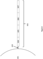
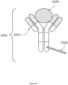
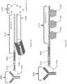
- FIG. 6 is a schematic diagram showing an example of a capture probe, as described herein. As shown, the capture probe 602 is optionally coupled to a capture spot 601 by a cleavage domain 603, such as a disulfide linker.
- a cleavage domain 603 such as a disulfide linker.
- a spatial barcode 605 can be included within the capture probe for use in barcoding the target analyte.
- the functional sequences can be selected for compatibility with a variety of different sequencing systems, e.g ., 454 Sequencing, Ion Torrent Proton or PGM, Illumina sequencing instruments, PacBio, Oxford Nanopore, etc ., and the requirements thereof.
- functional sequences can be selected for compatibility with non-commercialized sequencing systems. Examples of such sequencing systems and techniques, for which suitable functional sequences can be used, include (but are not limited to) Ion Torrent Proton or PGM sequencing, Illumina sequencing, PacBio SMRT sequencing, and Oxford Nanopore sequencing.
- functional sequences can be selected for compatibility with other sequencing systems, including non-commercialized sequencing systems.
- Capture probes can include ribonucleotides and/or deoxyribonucleotides as well as synthetic nucleotide residues that are capable of participating in Watson-Crick type or analogous base pair interactions.
- the capture domain is capable of priming a reverse transcription reaction to generate cDNA that is complementary to the captured RNA molecules.
- the capture domain of the capture probe can prime a DNA extension (polymerase) reaction to generate DNA that is complementary to the captured DNA molecules.
- the capture domain can template a ligation reaction between the captured DNA molecules and a surface probe that is directly or indirectly immobilized on the substrate.
- the capture domain can be ligated to one strand of the captured DNA molecules.
- the capture domain includes a poly(T) DNA oligonucleotide, e.g ., a series of consecutive deoxythymidine residues linked by phosphodiester bonds, which is capable of hybridizing to the poly(A) tail of mRNA.
- the capture domain can include nucleotides that are functionally or structurally analogous to a poly(T) tail.
- a poly-U oligonucleotide or an oligonucleotide included of deoxythymidine analogues includes at least 10, 11, 12, 13, 14, 15, 16, 17, 18, 19, or 20 nucleotides.
- the capture domain includes at least 25, 30, or 35 nucleotides.
- random sequences can be used to form all or a part of the capture domain.
- random sequences can be used in conjunction with poly(T) (or poly(T) analogue) sequences.
- a capture domain includes a poly(T) (or a "poly(T)-like") oligonucleotide
- it can also include a random oligonucleotide sequence (e.g ., "poly(T)-random sequence” probe). This can, for example, be located 5' or 3' of the poly(T) sequence, e.g ., at the 3' end of the capture domain.
- the poly(T)-random sequence probe can facilitate the capture of the mRNA poly(A) tail.
- the capture domain can be an entirely random sequence.
- degenerate capture domains can be used.
- a pool of two or more capture probes form a mixture, where the capture domain of one or more capture probes includes a poly(T) sequence and the capture domain of one or more capture probes includes random sequences. In some embodiments, a pool of two or more capture probes form a mixture where the capture domain of one or more capture probes includes poly(T)-like sequence and the capture domain of one or more capture probes includes random sequences. In some embodiments, a pool of two or more capture probes form a mixture where the capture domain of one or more capture probes includes a poly(T)-random sequences and the capture domain of one or more capture probes includes random sequences. In some embodiments, probes with degenerate capture domains can be added to any of the preceding combinations listed herein. In some embodiments, probes with degenerate capture domains can be substituted for one of the probes in each of the pairs described herein.
- the free 3' end of the capture domain can be blocked by chemical modification, e.g ., addition of an azidomethyl group as a chemically reversible capping moiety such that the capture probes do not include a free 3' end.
- Non-limiting examples of 3' modifications include dideoxy C-3' (3'-ddC), 3' inverted dT, 3' C3 spacer, 3'Amino, and 3' phosphorylation.
- the nucleic acid in the biological sample can be modified such that it can be captured by the capture domain.
- an adaptor sequence including a binding domain capable of binding to the capture domain of the capture probe
- this is achieved by ligation of the adaptor sequence or extension of the nucleic acid.
- an enzyme is used to incorporate additional nucleotides at the end of the nucleic acid sequence, e.g.
- the capture probes can be reversibly masked or modified such that the capture domain of the capture probe does not include a free 3' end. In some embodiments, the 3' end is removed, modified, or made inaccessible so that the capture domain is not susceptible to the process used to modify the nucleic acid of the biological sample, e.g ., ligation or extension.
- the capture domain of the capture probe is modified to allow the removal of any modifications of the capture probe that occur during modification of the nucleic acid molecules of the biological sample.
- the capture probes can include an additional sequence downstream of the capture domain, i.e., 3' to the capture domain, namely a blocking domain.
- Each capture probe can optionally include at least one cleavage domain.
- the cleavage domain represents the portion of the probe that is used to reversibly attach the probe to an array capture spot, as will be described further below.
- one or more segments or regions of the capture probe can optionally be released from the array capture spot by cleavage of the cleavage domain.
- spatial barcodes and/or universal molecular identifiers (UMIs) can be released by cleavage of the cleavage domain.
- FIG. 7 is a schematic illustrating a cleavable capture probe, where the cleaved capture probe can enter into a non-permeabilized cell and bind to target analytes within the sample.
- the capture probe 602 contains a cleavage domain 603, a cell penetrating peptide 703, a reporter molecule 704, and a disulfide bond (-S-S-). 705 represents all other parts of a capture probe, for example a spatial barcode and a capture domain.
- the cleavage domain 603 linking the capture probe to a capture spot is a covalent bond capable of cleavage by an enzyme.
- An enzyme can be added to cleave the cleavage domain, resulting in release of the capture probe from the capture spot.
- heating can also result in degradation of the cleavage domain and release of the attached capture probe from the array capture spot.
- laser radiation is used to heat and degrade cleavage domains of capture probes at specific locations.
- the cleavage domain is a photo-sensitive chemical bond (e.g ., a chemical bond that dissociates when exposed to light such as ultraviolet light).
- Oligonucleotides with photo-sensitive chemical bonds have various advantages. They can be cleaved efficiently and rapidly ( e.g ., in nanoseconds and milliseconds). In some cases, photo-masks can be used such that only specific regions of the array are exposed to cleavable stimuli (e.g ., exposure to UV light, exposure to light, exposure to heat induced by laser). When a photo-cleavable linker is used, the cleavable reaction is triggered by light, and can be highly selective to the linker and consequently biorthogonal. Typically, wavelength absorption for the photocleavable linker is located in the near-UV range of the spectrum.
- the cleavage domain includes one or more mismatch nucleotides, so that the complementary parts of the surface probe and the capture probe are not 100% complementary (for example, the number of mismatched base pairs can one, two, or three base pairs).
- a mismatch is recognized, e.g ., by the MutY and T7 endonuclease I enzymes, which results in cleavage of the nucleic acid molecule at the position of the mismatch.
- a "surface probe" can be any moiety present on the surface of the substrate capable of attaching to an agent ( e.g ., a capture probe).
- the surface probe is an oligonucleotide.
- the surface probe is part of the capture probe.
- nucleotides can be completely contiguous, e.g ., in a single stretch of adjacent nucleotides, or they can be separated into two or more separate subsequences that are separated by 1 or more nucleotides.
- Separated spatial barcode subsequences can be from about 4 to about 16 nucleotides in length. In some embodiments, the spatial barcode subsequence can be about 4, 5, 6, 7, 8, 9, 10, 11, 12, 13, 14, 15, 16 nucleotides or longer. In some embodiments, the spatial barcode subsequence can be at least about 4, 5, 6, 7, 8, 9, 10, 11, 12, 13, 14, 15, 16 nucleotides or longer. In some embodiments, the spatial barcode subsequence can be at most about 4, 5, 6, 7, 8, 9, 10, 11, 12, 13, 14, 15, 16 nucleotides or shorter.
- the one or more spatial barcode sequences of the multiple capture probes can include sequences that are the same for all capture probes coupled to the capture spot, and/or sequences that are different across all capture probes coupled to the capture spot.
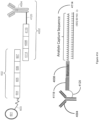
- FIG. 8 is a schematic diagram of an exemplary multiplexed spatially-labelled capture spot.
- the capture spot 601 can be coupled to spatially-barcoded capture probes, where the spatially-barcoded probes of a particular capture spot can possess the same spatial barcode, but have different capture domains designed to associate the spatial barcode of the capture spot with more than one target analyte.
- a capture spot may be coupled to four different types of spatially-barcoded capture probes, each type of spatially-barcoded capture probe possessing the spatial barcode 605.
- One type of capture probe associated with the capture spot includes the spatial barcode 605 in combination with a poly(T) capture domain 803, designed to capture mRNA target analytes.
- capture-probe barcoded constructs can be tailored for analyses of any given analyte associated with a nucleic acid and capable of binding with such a construct.
- the schemes shown in FIG. 8 can also be used for concurrent analysis of other analytes disclosed herein, including, but not limited to: (a) mRNA, a lineage tracing construct, cell surface or intracellular proteins and metabolites, and gDNA; (b) mRNA, accessible chromatin (e.g ., ATAC-seq, DNase-seq, and/or MNase-seq) cell surface or intracellular proteins and metabolites, and a perturbation agent (e.g ., a CRISPR crRNA/sgRNA, TALEN, zinc finger nuclease, and/or antisense oligonucleotide as described herein); (c) mRNA, cell surface or intracellular proteins and/or metabolites, a barcoded labelling agent (e.g .
- Capture probes attached to a single array capture spot can include identical (or common) spatial barcode sequences, different spatial barcode sequences, or a combination of both. Capture probes attached to a capture spot can include multiple sets of capture probes. Capture probes of a given set can include identical spatial barcode sequences. The identical spatial barcode sequences can be different from spatial barcode sequences of capture probes of another set.
- the capture probe can include one or more (e.g ., two or more, three or more, four or more, five or more) Unique Molecular Identifiers (UMIs).
- UMIs Unique Molecular Identifiers
- a unique molecular identifier is a contiguous nucleic acid segment or two or more non-contiguous nucleic acid segments that function as a label or identifier for a particular analyte, or for a capture probe that binds a particular analyte ( e.g ., via the capture domain).
- an individual array capture spot can include one or more capture probes.
- an individual array capture spot includes hundreds or thousands of capture probes.
- the capture probes are associated with a particular individual capture spot, where the individual capture spot contains a capture probe including a spatial barcode unique to a defined region or location on the array.
- a particular capture spot contains capture probes including more than one spatial barcode (e.g ., one capture probe at a particular capture spot can include a spatial barcode that is different than the spatial barcode included in another capture probe at the same particular capture spot, while both capture probes include a second, common spatial barcode), where each spatial barcode corresponds to a particular defined region or location on the array.
- multiple spatial barcode sequences associated with one particular capture spot on an array can provide a stronger address or attribution to a given location by providing duplicate or independent confirmation of the location.
- the multiple spatial barcodes represent increasing specificity of the location of the particular array point.
- a particular array point can be coded with two different spatial barcodes, where each spatial barcode identifies a particular defined region within the array, and an array point possessing both spatial barcodes identifies the sub-region where two defined regions overlap, e.g ., such as the overlapping portion of a Venn diagram.
- a particular array point can be coded with three different spatial barcodes, where the first spatial barcode identifies a first region within the array, the second spatial barcode identifies a second region, where the second region is a subregion entirely within the first region, and the third spatial barcode identifies a third region, where the third region is a subregion entirely within the first and second subregions.
- an array capture spot can include different types of capture probes attached to the capture spot.
- the array capture spot can include a first type of capture probe with a capture domain designed to bind to one type of analyte, and a second type of capture probe with a capture domain designed to bind to a second type of analyte.
- array capture spots can include one or more ( e.g ., two or more, three or more, four or more, five or more, six or more, eight or more, ten or more, 12 or more, 15 or more, 20 or more, 30 or more, 50 or more) different types of capture probes attached to a single array capture spot.
- the capture probe is nucleic acid. In some embodiments, the capture probe is attached to the array capture spot via its 5' end. In some embodiments, the capture probe includes from the 5' to 3' end: one or more barcodes ( e.g ., a spatial barcode and/or a UMI) and one or more capture domains. In some embodiments, the capture probe includes from the 5' to 3' end: one barcode ( e.g ., a spatial barcode or a UMI) and one capture domain.
- one barcode e.g ., a spatial barcode or a UMI
- the capture probe includes from the 5' to 3' end: a cleavage domain, a functional domain, one or more barcodes (e.g ., a spatial barcode and/or a UMI), and a capture domain.
- the capture probe includes from the 5' to 3' end: a cleavage domain, a functional domain, one or more barcodes (e.g ., a spatial barcode and/or a UMI), a second functional domain, and a capture domain.
- the capture probe includes from the 5' to 3' end: a cleavage domain, a functional domain, a spatial barcode, a UMI, and a capture domain.
- the capture probe does not include a spatial barcode.
- the capture probe does not include a UMI.
- the capture probe includes a sequence for initiating a sequencing reaction.
- the capture probe is immobilized on a capture spot via its 3' end.
- the capture probe includes from the 3' to 5' end: one or more barcodes (e.g ., a spatial barcode and/or a UMI) and one or more capture domains.
- the capture probe includes from the 3' to 5' end: one barcode (e.g ., a spatial barcode or a UMI) and one capture domain.
- the capture probe includes from the 3' to 5' end: a cleavage domain, a functional domain, one or more barcodes ( e.g ., a spatial barcode and/or a UMI), and a capture domain.
- the capture probe includes from the 3' to 5' end: a cleavage domain, a functional domain, a spatial barcode, a UMI, and a capture domain.
- a capture probe includes an in situ synthesized oligonucleotide.
- the in situ synthesized oligonucleotide can be attached to a substrate, or to a feature on a substrate.
- the in situ synthesized oligonucleotide includes one or more constant sequences, one or more of which serves as a priming sequence ( e . g ., a primer for amplifying target nucleic acids).
- the in situ synthesized oligonucleotide can, for example, include a constant sequence at the 3' end that is attached to a substrate, or attached to a feature on the substrate.
- the in situ synthesized oligonucleotide can include a constant sequence at the free 5' end.
- the one or more constant sequences can be a cleavable sequence.
- the in situ synthesized oligonucleotide includes a barcode sequence, e.g ., a variable barcode sequence.
- the barcode can be any of the barcodes described herein.
- the length of the barcode can be approximately 8 to 16 nucleotides ( e.g ., 8, 9, 10, 11, 12, 13, 14, 15, or 16 nucleotides).
- the length of the in situ synthesized oligonucleotide can be less than 100 nucleotides ( e.g ., less than 90, 80, 75, 70, 60, 50, 45, 40, 35, 30, 25 or 20 nucleotides). In some instances, the length of the in situ synthesized oligonucleotide is about 20 to about 40 nucleotides. Exemplary in situ synthesized oligonucleotides are produced by Affymetrix. In some embodiments, the in situ synthesized oligonucleotide is attached to a capture spot of an array.
- Additional oligonucleotides can be ligated to an in situ synthesized oligonucleotide to generate a capture probe.
- a primer complementary to a portion of the in situ synthesized oligonucleotide e.g ., a constant sequence in the oligonucleotide
- a primer complementary to a portion of the in situ synthesized oligonucleotide can be used to hybridize an additional oligonucleotide and extend (using the in situ synthesized oligonucleotide as a template e.g ., a primer extension reaction) to form a double stranded oligonucleotide and to further create a 3' overhang.
- the 3' overhang can be created by template-independent ligases (e.g ., terminal deoxynucleotidyl transferase (TdT) or poly(A) polymerase).
- An additional oligonucleotide comprising one or more capture domains can be ligated to the 3' overhang using a suitable enzyme (e.g ., a ligase) and a splint oligonucleotide, to generate a capture probe.
- a suitable enzyme e.g ., a ligase
- a capture probe can include a degenerate sequence, which is a sequence in which some positions of a nucleotide sequence contain a number of possible bases.
- a degenerate sequence can be a degenerate nucleotide sequence including about or at least 5, 6, 7, 8, 9, 10, 11, 12, 13, 14, 15, 16, 17, 18, 19, 20, 25, 30, 35, 40, 45, or 50 nucleotides.
- a nucleotide sequence contains 1, 2, 3, 4, 5, 6, 7, 8, 9, 0, 10, 15, 20, 25, or more degenerate positions within the nucleotide sequence.
- the degenerate sequence is used as a UMI.
- a blocking domain can be incorporated into the capture probe when it is synthesized, or after its synthesis.
- the terminal nucleotide of the capture domain is a reversible terminator nucleotide (e.g., 3'-O-blocked reversible terminator and 3'-unblocked reversible terminator), and can be included in the capture probe during or after probe synthesis.
- the capture domain of the capture probe includes a primer for producing the complementary strand of the nucleic acid hybridized to the capture probe, e.g. , a primer for DNA polymerase and/or reverse transcription.
- the nucleic acid, e.g ., DNA and/or cDNA, molecules generated by the extension reaction incorporate the sequence of the capture probe.
- the extension of the capture probe, e.g ., a DNA polymerase and/or reverse transcription reaction can be performed using a variety of suitable enzymes and protocols.
- RNA ligase a single stranded ligation enzyme
- Circligase TM available from Lucigen, Middleton, WI.
- template switching oligonucleotides are used to extend cDNA in order to generate a full-length cDNA (or as close to a full-length cDNA as possible).
- a second strand synthesis helper probe (a partially double stranded DNA molecule capable of hybridizing to the 3' end of the extended capture probe), can be ligated to the 3' end of the extended probe, e.g ., first strand cDNA, molecule using a double stranded ligation enzyme such as T4 DNA ligase.
- a polynucleotide tail e.g ., a poly(A) tail, is incorporated at the 3' end of the extended probe molecules. In some embodiments, the polynucleotide tail is incorporated using a terminal transferase active enzyme.
- extended capture probes are amplified to yield quantities that are sufficient for analysis, e.g., via DNA sequencing.
- the first strand of the extended capture probes e.g., DNA and/or cDNA molecules
- acts as a template for the amplification reaction e.g., a polymerase chain reaction.
- the extended capture probe or complement or amplicon thereof is released from an array feature.
- the step of releasing the extended capture probe or complement or amplicon thereof from an array feature can be achieved in a number of ways.
- an extended capture probe or a complement thereof is released from the feature by nucleic acid cleavage and/or by denaturation ( e.g., by heating to denature a double-stranded molecule).
- the capture probe can include one or more docking sequences (e.g., a first docking sequence and a second docking sequence) that can hybridize to one or more oligonucleotides (e.g., a padlock probe(s)) used for rolling circle amplification.
- additional probes are affixed to the substrate, where the additional probes include sequences (e.g., a docking sequence(s), a functional sequence(s), and/or a primer sequence(s)) that enable rolling circle amplification.
- the spatial array is contacted with an oligonucleotide (e.g., a padlock probe).
- rolling circle amplification can be used to amplify the ligation product, which includes at least a capture domain and a spatial barcode from the capture probe.
- amplification of the capture probe using a padlock oligonucleotide and rolling circle amplification increases the number of capture domains and the number of spatial barcodes on the spatial array.
- a method of increasing capture efficiency of a spatial array includes amplifying all or part of a capture probe affixed to a substrate. For example, amplification of all or part of the capture probes affixed to the substrate can increase the capture efficiency of the spatial array by increasing the number of capture domains and spatial barcodes.
- a method of determining a location of an analyte in a biological sample includes using a spatial array having increased capture efficiency (e.g., a spatial array where a capture probe has been amplified as described herein). For example, the capture efficiency of a spatial array can be increased by amplification of all or part of the capture probe prior to contact with a biological sample.
- a method of producing a spatial array that has increased capture efficiency includes amplifying all or part of a capture probe.
- a spatial array having increased capture efficiency is produced by amplifying all or part of a capture probe, the amplification increases the number of capture domains and the number of spatial barcodes on the spatial array.
- a method of determining the location of a capture probe (e.g., a capture probe on a feature) on a spatial array includes amplifying all or part of a capture probe.
- an “analyte capture agent” (also referred to previously at times as a “cell labelling” agent”) refers to an agent that interacts with an analyte (e.g ., an analyte in a sample) and with a capture probe (e.g ., a capture probe attached to a substrate) to identify the analyte.
- the analyte capture agent includes an analyte binding moiety and a capture agent barcode domain.
- an analyte binding moiety 4004 of an analyte capture agent 4002 includes one or more antibodies or antigen binding fragments thereof.
- the antibodies or antigen binding fragments including the analyte binding moiety 4004 can specifically bind to a target analyte.
- the analyte 4006 is a protein (e.g., a protein on a surface of the biological sample, such as a cell, or an intracellular protein).
- a plurality of analyte capture agents comprising a plurality of analyte binding moieties bind a plurality of analytes present in a biological sample.
- the analyte binding moieties of the plurality of analyte capture agents are the different (e.g ., members of the plurality of analyte capture agents can have two or more species of analyte binding moieties, where each of the two or more species of analyte binding moieties binds a single species of analyte, e.g ., at different binding sites).
- the plurality of analytes includes multiple different species of analyte ( e.g ., multiple different species of polypeptides).
- exemplary, non-limiting antibodies that can be used as analyte binding moieties 4004 in an analyte capture agent 4002 or that can be used in the applications disclosed herein include any of the following antibodies (and variations thereof) to: cell surface proteins, intracellular proteins, kinases (e.g ., AGC kinase family such as AKT1, AKT2, PDK1, Protein Kinase C, ROCK1, ROCK2, SGK3), CAMK kinase family ( e.g ., AMPK1, AMPK2, CAMK, Chk1, Chk2, Zip), CK1 kinase family, TK kinase family ( e.g ., Abl2, AXL, CD167, CD246/ALK, c-Met, CSK, c-Src, EGFR, ErbB2 (HER2/neu), ErbB3, ErbB4, FAK, Fyn, LCK, Lyn, PKT7, Syk, Za
- the analyte capture agents 4002 are capable of binding to cell surface analytes that are posttranslationally modified.
- analyte capture agents can be specific for cell surface analytes based on a given state of posttranslational modification (e.g ., phosphorylation, glycosylation, ubiquitination, nitrosylation, methylation, acetylation or lipidation), such that a cell surface analyte profile can include posttranslational modification information of one or more analytes.
- analyte binding moiety barcode refers to a barcode that is associated with or otherwise identifies the analyte binding moiety 4004. In some embodiments, by identifying an analyte binding moiety 4004 and its associated analyte binding moiety barcode, the analyte 4006 to which the analyte binding moiety binds 4004 can also be identified.
- An analyte binding moiety barcode can be a nucleic acid sequence of a given length and/or sequence that is associated with the analyte binding moiety 4004.
- An analyte binding moiety barcode can generally include any of the variety of aspects of barcodes described herein.
- the capture agent barcode domain of an analyte capture agent 4002 includes an analyte capture sequence.
- analyte capture sequence refers to a region or moiety configured to hybridize to, bind to, couple to, or otherwise interact with a capture domain of a capture probe.
- an analyte capture sequence includes a nucleic acid sequence that is complementary to or substantially complementary to the capture domain of a capture probe such that the analyte capture sequence hybridizes to the capture domain of the capture probe.
- an analyte capture sequence comprises a poly(A) nucleic acid sequence that hybridizes to a capture domain that comprises a poly(T) nucleic acid sequence.
- an analyte capture sequence comprises a poly(T) nucleic acid sequence that hybridizes to a capture domain that comprises a poly(A) nucleic acid sequence. In some embodiments, an analyte capture sequence comprises a non-homopolymeric nucleic acid sequence that hybridizes to a capture domain that comprises a non-homopolymeric nucleic acid sequence that is complementary (or substantially complementary) to the non-homopolymeric nucleic acid sequence of the analyte capture region.
- the capture agent barcode domain can be directly coupled to the analyte binding moiety 4004, or they can be attached to a bead, molecular lattice, e.g ., a linear, globular, cross-slinked, or other polymer, or other framework that is attached or otherwise associated with the analyte binding moiety, which allows attachment of multiple capture agent barcode domains to a single analyte binding moiety.
- Attachment (coupling) of the capture agent barcode domains to the analyte binding moieties 4004 can be achieved through any of a variety of direct or indirect, covalent or non-covalent associations or attachments.
- capture agent barcode domains can be covalently attached to a portion of the antibody or antigen-binding fragment using chemical conjugation techniques (e.g ., LIGHTNING-LINK ® antibody labelling kits available from Innova Biosciences).
- chemical conjugation techniques e.g ., LIGHTNING-LINK ® antibody labelling kits available from Innova Biosciences.
- the antibody can be glycosylated with a chemical substrate-permissive mutant of ⁇ -1,4-galactosyltransferase, GalT (Y289L) and azide-bearing uridine diphosphate-N-acetylgalactosamine analog uridine diphosphate -GalNAz.
- the modified antibody can be conjugated to an oligonucleotide with a dibenzocyclooctyne-PEG4-NHS group.
- certain steps e.g ., COOH activation such as EDC
- homobifunctional cross linkers can be avoided to prevent the analyte binding moieties from conjugating to themselves.
- the analyte capture agent e.g ., analyte binding moiety 4004 coupled to an oligonucleotide
- the analyte capture agent can be delivered into the cell, e.g ., by transfection (e.g ., using transfectamine, cationic polymers, calcium phosphate or electroporation), by transduction ( e.g ., using a bacteriophage or recombinant viral vector), by mechanical delivery (e.g ., magnetic beads), by lipid (e.g ., 1,2-dioleoyl-sn-glycero-3-phosphocholine (DOPC)), or by transporter proteins.
- transfection e.g ., using transfectamine, cationic polymers, calcium phosphate or electroporation
- transduction e.g ., using a bacteriophage or recombinant viral vector
- mechanical delivery e.g ., magnetic beads
- lipid e.g
- the cell is permeabilized to allow the analyte capture agent 4002 to couple with intracellular constituents (such as, without limitation, intracellular proteins, metabolites, and nuclear membrane proteins).
- intracellular constituents such as, without limitation, intracellular proteins, metabolites, and nuclear membrane proteins.
- analyte capture agents 4002 can be used to analyze intracellular constituents as described herein.
- the capture agent barcode domain coupled to an analyte capture agent 4002 can include modifications that render it non-extendable by a polymerase.
- the capture agent barcode domain when binding to a capture domain of a capture probe or nucleic acid in a sample for a primer extension reaction, the capture agent barcode domain can serve as a template, not a primer.
- the capture agent barcode domain also includes a barcode (e.g., an analyte binding moiety barcode)
- such a design can increase the efficiency of molecular barcoding by increasing the affinity between the capture agent barcode domain and unbarcoded sample nucleic acids, and eliminate the potential formation of adaptor artifacts.
- a modification for blocking primer extension by a polymerase can be a carbon spacer group of different lengths or a dideoxynucleotide.
- the modification can be an abasic site that has an apurine or apyrimidine structure, a base analog, or an analogue of a phosphate backbone, such as a backbone of N-(2-aminoethyl)-glycine linked by amide bonds, tetrahydrofuran, or 1', 2'-Dideoxyribose.
- the modification can also be a uracil base, 2'OMe modified RNA, C3-18 spacers (e.g ., structures with 3-18 consecutive carbon atoms, such as C3 spacer), ethylene glycol multimer spacers ( e.g ., spacer 18 (hexa-ethyleneglycol spacer)), biotin, di-deoxynucleotide triphosphate, ethylene glycol, amine, or phosphate).
- C3-18 spacers e.g ., structures with 3-18 consecutive carbon atoms, such as C3 spacer
- ethylene glycol multimer spacers e.g ., spacer 18 (hexa-ethyleneglycol spacer)
- biotin di-deoxynucleotide triphosphate
- ethylene glycol, amine, or phosphate ethylene glycol, amine, or phosphate
- the capture agent barcode domain 4008 coupled to the analyte binding moiety 4004 includes a cleavable domain.
- the capture agent barcode domain can be cleaved and collected for downstream analysis according to the methods as described herein.
- the cleavable domain of the capture agent barcode domain includes a U-excising element that allows the species to release from the bead.
- the U-excising element can include a single-stranded DNA (ssDNA) sequence that contains at least one uracil.
- multiple different species of analytes from the biological sample can be subsequently associated with the one or more physical properties of the biological sample.
- the multiple different species of analytes can be associated with locations of the analytes in the biological sample.
- Such information e.g., proteomic information when the analyte binding moiety(ies) recognizes a polypeptide(s)
- spatial information e.g., genetic information from the biological sample, such as DNA sequence information, transcriptome information, for example sequences of transcripts, or both).
- the analyte capture agent 4002 bound to the cell surface protein can be bound to a capture probe (e.g ., a capture probe on an array), which capture probe includes a capture domain that interacts with an analyte capture sequence present on the capture agent barcode domain of the analyte capture agent 902.
- All or part of the capture agent barcode domain can be copied with a polymerase using a 3' end of the capture domain as a priming site, generating an extended capture probe that includes the all or part of complementary sequence that corresponds to the capture probe (including a spatial barcode present on the capture probe) and a copy of the analyte binding moiety barcode.
- an analyte capture agent with an extended capture agent barcode domain that includes a sequence complementary to a spatial barcode of a capture probe is called a "spatially-tagged analyte capture agent.”
- the spatial array with spatially-tagged analyte capture agents can be contacted with a sample, where the analyte capture agent(s) associated with the spatial array capture the target analyte(s).
- the analyte capture agent(s) containing the extended capture probe(s), which includes a sequence complementary to the spatial barcode(s) of the capture probe(s) and the analyte binding moiety barcode(s) can then be denatured from the capture probe(s) of the spatial array. This allows the spatial array to be reused.
- the sample can be dissociated into non-aggregated cells (e.g., single cells) and analyzed by the single cell / droplet methods described herein.
- FIG. 41A is a schematic diagram depicting an exemplary interaction between a feature-immobilized capture probe 602 and an analyte capture agent 4002 (where the terms “feature” and “capture spot” are used interchangeably).
- the feature-immobilized capture probe 602 can include a spatial barcode 605 as well as one or more functional sequences 604 and 606, as described elsewhere herein.
- the capture probe 602 can also include a capture domain 607 that is capable of binding to an analyte capture agent 4002.
- the analyte capture agent 4002 comprises a functional sequence 4118, capture agent barcode domain 4008, and an analyte capture sequence 4114.
- FIG. 41A bottom panel, further illustrates a spatially-tagged analyte capture agent 4002 in which the analyte capture sequence 4114 (poly-A sequence) of the capture agent barcode domain 4118/4008/4114 can be blocked with a blocking probe (poly-T oligonucleotide).
- analyte capture sequence 4114 poly-A sequence
- a blocking probe poly-T oligonucleotide
- the blocking probe sequence is not on a contiguous sequence with the capture binding domain.
- the capture binding domain also herein called a first sequence
- the blocking sequence are independent polynucleotides.
- capture binding domain and first sequence are used interchangeably in this disclosure.
- the first sequence can be a poly(A) sequence when the capture domain sequence of the capture probe on the substrate is a poly(T) sequence.
- the capture binding domain includes a capture binding domain substantially complementary to the capture domain of the capture probe.
- substantially complementary it is meant that the first sequence of the capture binding domain is at least 70%, at least 75%, at least 80%, at least 85%, at least 90%, at least 91%, at least 92%, at least 93%, at least 94%, at least 95%, at least 96%, at least 97%, at least 98%, at least 99%, or 100% complementary to a sequence in the capture domain of the capture probe.
- the first sequence of the capture binding domain can be a random sequence (e.g., random hexamer) that is at least partially complementary to a capture domain sequence of the capture probe that is also a random sequence.
- a capture binding domain can be a mixture of a homopolymeric sequence (e.g., a poly(T) sequence) and a random sequence ( e.g., random hexamer) when a capture domain sequence of the capture probe is also a sequence that includes a homopolymeric sequence (e.g., a poly(A) sequence) and a random sequence.
- the second sequence (e.g., the blocking probe) of the capture binding domain includes a nucleic acid sequence.
- the second sequence is also called a blocking probe or blocking domain, and each term is used interchangeably.
- the blocking domain is a DNA oligonucleotide.
- the blocking domain is an RNA oligonucleotide.
- a blocking probe of the capture binding domain includes a sequence that is complementary or substantially complementary to a first sequence of the capture binding domain. In some embodiments, the blocking probe prevents the first sequence of the capture binding domain from binding the capture domain of the capture probe when present.
- the blocking probe of the capture binding domain includes a homopolymeric sequence that is substantially complementary to the first sequence of the capture binding domain. In some embodiments, the blocking probe is configured to hybridize to a poly(A), poly(T), or a poly-rU sequence. In some embodiments, the blocking probe includes a poly(A), poly(T), or a poly(U) sequence. In some embodiments, the first sequence includes a homopolymeric sequence. In some embodiments, the first sequence includes a poly(A), poly(U), or a poly(T) sequence.
- 4150 exemplifies a nuclease capable of digesting the blocking sequencing.
- 4150 could be an endonuclease or mixture of nucleases capable of digesting uracils, such as UDG or a uracil specific excision mix such as USER (NEB).
- the hairpin sequence 4170 is located 5' of the blocking probe in the capture binding domain. In some embodiments, the hairpin sequence 4170 is located 5' of the first sequence in the capture binding domain. In some embodiments, the capture binding domain includes from 5' to 3' a first sequence substantially complementary to the capture domain of a capture probe, a hairpin sequence, and a blocking probe substantially complementary to the first sequence. Alternatively, the capture binding domain includes from 3' to 5' a first sequence substantially complementary to the capture domain of a capture probe, a hairpin sequence, and a blocking probe substantially complementary to the first sequence.
- the hairpin sequence includes DNA, RNA, DNA-RNA hybrid, or includes modified nucleotides.
- the hairpin is a poly(U) sequence.
- the RNA hairpin sequence is digested by USER and/or RNAse H using methods disclosed herein.
- the poly(U) hairpin sequence is digested by USER and/or RNAse H using methods disclosed herein.
- the hairpin is a poly(T) sequence.
- methods provided herein require that the second sequence (e.g., the blocking probe) of the capture binding domain that is hybridized to the first sequence of the capture binding domain is released from the first sequence.
- releasing the blocking probe (or second sequence) from the first sequence is performed under conditions where the blocking probe de-hybridizes from the first sequence.
- the hairpin sequence 4170 further includes a sequence that is capable of binding to a capture domain of a capture probe. For example, releasing the hairpin sequence from the capture binding domain can require that the hairpin sequence is cleaved, where the portion of the hairpin sequence that is left following cleavage includes a sequence that is capable of binding to a capture domain of a capture probe. In some embodiments, all or a portion of the hairpin sequence is substantially complementary to a capture domain of a capture probe. In some embodiments, the sequence that is substantially complementary to a capture domain of a capture probe is located on the free 5' or free 3' end following cleavage of the hairpin sequence.
- the one or more blocking methods disclosed herein include a plurality of caged nucleotides.
- a capture binding domain includes a plurality of caged nucleotides.
- the caged nucleotides prevent the capture binding domain from interacting with the capture domain of the capture probe.
- the caged nucleotides include caged moieties that block Watson-Crick hydrogen bonding, thereby preventing interaction until activation, for example, through photolysis of the caged moiety that releases the caged moiety and restores the caged nucleotides ability to engage in Watson-Crick base pairing with a complement nucleotide.
- the caged nucleotides include a caged moiety selected from the group of 6-nitropiperonyloxymethy (NPOM), 1-(ortho-nitrophenyl)-ethyl (NPE), 2-(ortho-nitrophenyl)propyl (NPP), diethylaminocoumarin (DEACM), and nitrodibenzofuran (NDBF).
- NPOM 6-nitropiperonyloxymethy
- NPE 1-(ortho-nitrophenyl)-ethyl
- NPP 2-(ortho-nitrophenyl)propyl
- DEACM diethylaminocoumarin
- NDBF nitrodibenzofuran
- a caged nucleotide includes a non-naturally-occurring nucleotide selected from the group consisting of 6-nitropiperonyloxymethy (NPOM)-caged adenosine, 6-nitropiperonyloxymethy (NPOM)-caged guanosine, 6-nitropiperonyloxymethy (NPOM)-caged uridine, and 6-nitropiperonyloxymethy (NPOM)-caged thymidine.
- the capture binding domain includes one or more caged nucleotides where the cage nucleotides include one or more 6-nitropiperonyloxymethy (NPOM)-caged guanosine.
- the capture binding domain includes one or more caged nucleotides where the cage nucleotides include one or more nitropiperonyloxymethy (NPOM)-caged uridine. In yet another example, the capture binding domain includes one or more caged nucleotides where the caged nucleotide includes one or more 6-nitropiperonyloxymethy (NPOM)-caged thymidine.
- the capture binding domain includes a combination of at least two or more of any of the caged nucleotides described herein.
- the capture binding domain can include one or more 6-nitropiperonyloxymethy (NPOM)-caged guanosine and one or more nitropiperonyloxymethy (NPOM)-caged uridine. It is appreciated that a capture binding domain can include any combination of any of the caged nucleotides described herein.
- the capture binding domain includes a caged nucleotide at the 3' end. In some embodiments, the capture binding domain includes two caged nucleotides at the 3' end. In some embodiments, the capture binding domain includes at least three caged nucleotides at the 3' end.
- the capture binding domain includes a sequence including at least 10%, at least, 20%, or at least 30% caged nucleotides. In some instances, the percentage of caged nucleotides in the capture binding domain is about 40%, about 50%, about 60%, about 70%, about 80% or higher. In some embodiments, the capture binding domain includes a sequence where every nucleotide is a caged nucleotide. It is understood that the limit of caged nucleotides is based on the sequence of the capture binding domain and on steric limitations of creating caged nucleotides in proximity to one another. Thus, in some instances, particular nucleotides (e.g ., guanines) are replaced with caged nucleotides.
- particular nucleotides e.g ., guanines
- the capture binding domain includes caged nucleotides that are evenly distributed throughout the capture binding domain.
- a capture binding domain can include a sequence that includes at least 10% caged nucleotides where the caged nucleotides are evenly distributed throughout the capture binding domain.
- the capture binding domain includes a sequence that is at least 10% caged nucleotides and where the 10% caged nucleotides are positioned at the 3' of the capture binding domain.
- the capture binding domain includes a sequence that is at least 10% caged nucleotides and where the 10% caged nucleotides are positioned at the 5' end of the capture binding domain.
- the caged nucleotides are included at every third, at every fourth, at every fifth, at every sixth nucleotide, or a combination thereof, of the capture binding domain sequence.
- releasing the caged moiety from the caged nucleotide includes activating the caged moiety.
- releasing the caged moiety from the caged nucleotide restores the caged nucleotides ability to hybridize to a complementary nucleotide through Watson-Crick hydrogen bonding. For example, restoring the caged nucleotides ability to hybridize with a complementary nucleotide enables/restores the capture binding domain's ability to interact with the capture domain.
- the substrate can also correspond to a flow cell.
- Flow cells can be formed of any of the foregoing materials, and can include channels that permit reagents, solvents, capture spots, and molecules to pass through the flow cell.
- polystyrene is a hydrophobic material suitable for binding negatively charged macromolecules because it normally contains few hydrophilic groups.
- nucleic acids immobilized on glass slides by increasing the hydrophobicity of the glass surface the nucleic acid immobilization can be increased.
- Such an enhancement can permit a relatively more densely packed formation (e.g., provide improved specificity and resolution).
- a substrate is coated with a surface treatment such as poly-L-lysine. Additionally or alternatively, the substrate can be treated by silanation, e.g., with epoxy-silane, amino-silane, and/or by a treatment with polyacrylamide.
- the substrate can generally have any suitable form or format.
- the substrate can be flat, curved, e.g., convexly or concavely curved towards the area where the interaction between a biological sample, e.g., tissue sample, and the substrate takes place.
- the substrate is a flat, e.g., planar, chip or slide.
- the substrate can contain one or more patterned surfaces within the substrate ( e.g., channels, wells, projections, ridges, divots, etc.).
- Substrates can optionally include various structures such as, but not limited to, projections, ridges, and channels.
- a substrate can be micropatterned to limit lateral diffusion (e.g., to prevent overlap of spatial barcodes).
- a substrate modified with such structures can be modified to allow association of analytes, capture spots (e.g., beads), or probes at individual sites.
- the sites where a substrate is modified with various structures can be contiguous or non-contiguous with other sites.
- a substrate includes one or more markings on a surface of the substrate, e.g., to provide guidance for correlating spatial information with the characterization of the analyte of interest.
- a substrate can be marked with a grid of lines (e.g., to allow the size of objects seen under magnification to be easily estimated and/or to provide reference areas for counting objects).
- fiducial markers can be included on the substrate. Such markings can be made using techniques including, but not limited to, printing, sandblasting, and depositing on the surface.
- the structures can include physically altered sites.
- a substrate modified with various structures can include physical properties, including, but not limited to, physical configurations, magnetic or compressive forces, chemically functionalized sites, chemically altered sites, and/or electrostatically altered sites.
- the structures are applied in a pattern.
- the structures can be randomly distributed.
- a substrate is treated in order to minimize or reduce non-specific analyte hybridization within or between capture spots.
- treatment can include coating the substrate with a hydrogel, film, and/or membrane that creates a physical barrier to non-specific hybridization.
- Any suitable hydrogel can be used.
- hydrogel matrices prepared according to the methods set forth in U.S. Patent Nos. 6,391,937 , 9,512,422 , and 9,889,422 , and U.S. Patent Application Publication Nos. U.S. 2017/0253918 and U.S. 2018/0052081 can be used. The entire contents of each of the foregoing documents are incorporated herein by reference.
- Treatment can include adding a functional group that is reactive or capable of being activated such that it becomes reactive after receiving a stimulus (e.g., photoreactive).
- Treatment can include treating with polymers having one or more physical properties (e.g., mechanical, electrical, magnetic, and/or thermal) that minimize non-specific binding (e.g., that activate a substrate at certain locations to allow analyte hybridization at those locations).
- Non-limiting examples of a cell-permissive coating include coatings that feature one or more extracellular matrix (ECM) components (e.g ., proteoglycans and fibrous proteins such as collagen, elastin, fibronectin and laminin), poly-lysine, poly-L-ornithine, and/or a biocompatible silicone (e.g ., CYTOSOFT ® ).
- ECM extracellular matrix
- a cell-permissive coating that includes one or more extracellular matrix components can include collagen Type I, collagen Type II, collagen Type IV, elastin, fibronectin, laminin, and/or vitronectin.
- the cell-permissive coating includes a solubilized basement membrane preparation extracted from the Engelbreth-Holm-Swarm (EHS) mouse sarcoma (e.g ., MATRIGEL ® ). In some embodiments, the cell-permissive coating includes collagen.
- EHS Engelbreth-Holm-Swarm
- MATRIGEL ® solubilized basement membrane preparation extracted from the Engelbreth-Holm-Swarm
- the cell-permissive coating includes collagen.
- oligonucleotides within the gel can attach to the substrate.
- a gel e.g ., a hydrogel or gel matrix
- oligonucleotides within the gel can attach to the substrate.
- the terms "hydrogel” and “hydrogel matrix” are used interchangeably herein to refer to a macromolecular polymer gel including a network. Within the network, some polymer chains can optionally be cross-linked, although cross-linking does not always occur.
- substrates including for example fiducial markers on such substrates, are disclosed in PCT publication 202020176788A1 entitled “Profiling of biological analyes with spatially barcoded oligonucleotide arrays" which is hereby incorporated by reference.
- capture spots are collectively positioned on a substrate.
- An “array” is a specific arrangement of a plurality of capture spots (also termed “features”) that is either irregular or forms a regular pattern. Individual capture spots in the array differ from one another based on their relative spatial locations. In general, at least two of the plurality of capture spots in the array include a distinct capture probe ( e.g., any of the examples of capture probes described herein).
- a "capture spot” is an entity that acts as a support or repository for various molecular entities used in sample analysis.
- capture spots include, but are not limited to, a bead, a spot of any twoor three-dimensional geometry (e.g ., an inkjet spot, a masked spot, a square on a grid), a well, and a hydrogel pad.
- capture spots are directly or indirectly attached or fixed to a substrate ( e.g ., of a chip).
- the capture spots are not directly or indirectly attached or fixed to a substrate, but instead, for example, are disposed within an enclosed or partially enclosed three dimensional space (e.g ., wells or divots).
- capture spots are directly or indirectly attached or fixed to a substrate ( e.g ., of a chip) that is liquid permeable. In some embodiments, capture spots are directly or indirectly attached or fixed to a substrate that is biocompatible. In some embodiments, capture spots are directly or indirectly attached or fixed to a substrate that is a hydrogel.
- the term "bead array” refers to an array that includes a plurality of beads as the capture spots in the array.
- the beads are attached to a substrate (e.g., of a chip).
- the beads can optionally attach to a substrate such as a microscope slide and in proximity to a biological sample (e.g., a tissue section that includes cells).
- the beads can also be suspended in a solution and deposited on a surface (e.g., a membrane, a tissue section, or a substrate (e.g., a microscope slide)).
- some or all capture spots in an array include a capture probe.
- an array can include a capture probe attached directly or indirectly to the substrate.
- a substrate includes one or more capture probes that are designed to capture analytes from one or more organisms.
- a substrate can contain one or more capture probes designed to capture mRNA from one organism (e.g., a human) and one or more capture probes designed to capture DNA from a second organism (e.g., a bacterium).
- the capture probes can be attached to a substrate or capture spot using a variety of techniques.
- the capture probe is directly attached to a capture spot that is fixed on an array.
- the capture probes are immobilized to a substrate by chemical immobilization.
- a chemical immobilization can take place between functional groups on the substrate and corresponding functional elements on the capture probes.
- Exemplary corresponding functional elements in the capture probes can either be an inherent chemical group of the capture probe, e.g., a hydroxyl group, or a functional element can be introduced on to the capture probe.
- An example of a functional group on the substrate is an amine group.
- the capture probe to be immobilized includes a functional amine group or is chemically modified in order to include a functional amine group. Means and methods for such a chemical modification are well known in the art.
- the capture probe is immobilized on a capture spot or a substrate via its 5' end and includes from the 5' to 3' end: a cleavage domain, a functional domain, one or more barcodes (e.g., a spatial barcode and/or a UMI), and a capture domain.
- the capture probe is immobilized on a capture spot or a substrate via its 5' end and includes from the 5' to 3' end: a cleavage domain, a functional domain, one or more barcodes (e.g., a spatial barcode and/or a UMI), a second functional domain, and a capture domain.
- the capture probe is immobilized on a capture spot or a substrate via its 5' end and includes from the 5' to 3' end: a cleavage domain, a functional domain, a spatial barcode, a UMI, and a capture domain.
- the capture probe is immobilized on a capture spot or a substrate via its 5' end and does not include a spatial barcode.
- the capture probe is immobilized on a capture spot or a substrate via its 5' end and does not include a UMI.
- the capture probe includes a sequence for initiating a sequencing reaction.
- the capture probe is immobilized on a capture spot or a substrate via its 3' end and includes from the 3' to 5' end: a cleavage domain, a functional domain, one or more barcodes (e.g., a spatial barcode and/or a UMI), and a capture domain.
- the capture probe is immobilized on a capture spot or a substrate via its 3' end and includes from the 3' to 5' end: a cleavage domain, a functional domain, a spatial barcode, a UMI, and a capture domain.
- a capture probe can further include a support (e.g., a support attached to the capture probe, a support attached to the capture spot, or a support attached to the substrate).
- a typical support for a capture probe to be immobilized includes moieties which are capable of binding to such capture probes, e.g., to amine-functionalized nucleic acids. Examples of such supports are carboxy, aldehyde, or epoxy supports.
- the substrates on which capture probes can be immobilized can be chemically activated, e.g., by the activation of functional groups, available on the substrate.
- activated substrate relates to a material in which interacting or reactive chemical functional groups are established or enabled by chemical modification procedures.
- a substrate including carboxyl groups can be activated before use.
- certain substrates contain functional groups that can react with specific moieties already present in the capture probes.
- a covalent linkage is used to directly couple a capture probe to a substrate.
- a capture probe is indirectly coupled to a substrate through a linker separating the "first" nucleotide of the capture probe from the support, i.e., a chemical linker.
- a capture probe does not bind directly to the array, but interacts indirectly, for example by binding to a molecule which itself binds directly or indirectly to the array.
- the capture probe is indirectly attached to a substrate ( e.g., via a solution including a polymer).
- Methods for covalent attachment also include, for example, click chemistry reactions, including [3+2] cycloaddition reactions (e.g., Huisgen 1,3-dipolar cycloaddition reaction and copper(I)-catalyzed azide-alkyne cycloaddition (CuAAC)); thiol-ene reactions; the Diels-Alder reaction and inverse electron demand Diels-Alder reaction; [4+1] cycloaddition of isonitriles and tetrazines; and nucleophilic ring-opening of small carbocycles (e.g., epoxide opening with amino oligonucleotides).
- click chemistry reactions including [3+2] cycloaddition reactions (e.g., Huisgen 1,3-dipolar cycloaddition reaction and copper(I)-catalyzed azide-alkyne cycloaddition (CuAAC)); thiol-en
- functionalized biomolecules e.g. , capture probes are immobilized on a functionalized substrate using non-covalent methods.
- Methods for non-covalent attachment include, for example, biotin-functionalized oligonucleotides and streptavidin-treated substrates (see, e.g. , Holmstr ⁇ m et al. (1993) Analytical Biochemistry 209, 278-283 and Gilles et al. (1999) Nature Biotechnology 17, 365-370 , the entire contents of which are herein incorporated by reference).
- an oligonucleotide e.g ., a capture probe
- a substrate or capture spot can be attached to a substrate or capture spot according to the methods set forth in U.S. Patent Nos. 6,737,236 , 7,259,258 , 7,375,234 , 7,427,678 , 5,610,287 , 5,807,522 , 5,837,860 , and 5,472,881 ; U.S. Patent Application Publication Nos. 2008/0280773 and 2011/0059865 ; Shalon et al. (1996) Genome Research, 639-645 ; Rogers et al. (1999) Analytical Biochemistry 266, 23-30 ; Stimpson et al.
- the surface of a substrate is coated with a cell permissive coating to facilitate adherence of live cells.
- a "cell-permissive coating” is a coating that allows or helps cells to maintain cell viability (e.g ., remain viable) on the substrate.
- a cell-permissive coating can enhance cell attachment, cell growth, and/or cell differentiation, e.g ., a cell-permissive coating can provide nutrients to the live cells.
- a cell-permissive coating can include a biological material and/or a synthetic material.
- the cell-permissive coating includes a solubilized basement membrane preparation extracted from the Engelbreth-Holm-Swarm (EHS) mouse sarcoma (e.g. , MATRIGEL ® ). In some embodiments, the cell-permissive coating includes collagen.
- EHS Engelbreth-Holm-Swarm
- MATRIGEL ® MATRIGEL
- a “conditionally removable coating” is a coating that can be removed from the surface of a substrate upon application of a releasing agent.
- a conditionally removable coating includes a hydrogel as described in further detail in U.S. Patent Application Number 16/992,569 entitled “Systems and Methods for Using the Spatial Distribution of Haplotypes to Determine a Biological Condition," filed August 13, 2020 .
- arrays can be prepared by a variety of methods.
- arrays are prepared through the synthesis (e.g., in-situ synthesis) of oligonucleotides on the array, or by jet printing or lithography.
- synthesis e.g., in-situ synthesis
- light-directed synthesis of high-density DNA oligonucleotides can be achieved by photolithography or solid-phase DNA synthesis.
- synthetic linkers modified with photochemical protecting groups can be attached to a substrate and the photochemical protecting groups can be modified using a photolithographic mask (applied to specific areas of the substrate) and light, thereby producing an array having localized photodeprotection.
- the arrays are "spotted” or “printed” with oligonucleotides and these oligonucleotides (e.g., capture probes) are then attached to the substrate.
- the oligonucleotides can be applied by either noncontact or contact printing.
- a noncontact printer can use the same method as computer printers (e.g., bubble jet or inkjet) to expel small droplets of probe solution onto the substrate.
- the specialized inkjet-like printer can expel nanoliter to picoliter volume droplets of oligonucleotide solution, instead of ink, onto the substrate.
- each print pin directly applies the oligonucleotide solution onto a specific location on the surface.
- the oligonucleotides can be attached to the substrate surface by the electrostatic interaction of the negative charge of the phosphate backbone of the DNA with a positively charged coating of the substrate surface or by UV-cross-linked covalent bonds between the thymidine bases in the DNA and amine groups on the treated substrate surface.
- the substrate is a glass slide.
- the oligonucleotides e.g., capture probes
- the substrate is a covalent bond to a chemical matrix, e.g., epoxy-silane, amino-silane, lysine, polyacrylamide, etc.
- the inkjet spotting process can also be used for in-situ oligonucleotide synthesis.
- the different nucleotide precursors plus catalyst can be printed on the substrate, and are then combined with coupling and deprotection steps. This method relies on printing picoliter volumes of nucleotides on the array surface in repeated rounds of base-by-base printing that extends the length of the oligonucleotide probes on the array.
- an array comprising barcoded probes can be generated through ligation of a plurality of oligonucleotides.
- an oligonucleotide of the plurality contains a portion of a barcode, and the complete barcode is generated upon ligation of the plurality of oligonucleotides.
- a first oligonucleotide containing a first portion of a barcode can be attached to a substrate (e.g., using any of the methods of attaching an oligonucleotide to a substrate described herein), and a second oligonucleotide containing a second portion of the barcode can then be ligated onto the first oligonucleotide to generate a complete barcode.
- a substrate e.g., using any of the methods of attaching an oligonucleotide to a substrate described herein
- a second oligonucleotide containing a second portion of the barcode can then be ligated onto the first oligonucleotide to generate a complete barcode.
- Different combinations of the first, second and any additional portions of a barcode can be used to increase the diversity of the barcodes.
- the first and/or the second oligonucleotide can be attached to the substrate via a surface linker which contains a cleavage site.
- the ligated oligonucleotide is linearized by cleaving at the cleavage site.
- a plurality of second oligonucleotides comprising two or more different barcode sequences can be ligated onto a plurality of first oligonucleotides that comprise the same barcode sequence, thereby generating two or more different species of barcodes.
- a first oligonucleotide attached to a substrate containing a first portion of a barcode can initially be protected with a protective group (e.g., a photocleavable protective group), and the protective group can be removed prior to ligation between the first and second oligonucleotide.
- a protective group e.g., a photocleavable protective group
- a concentration gradient of the oligonucleotides can be applied to a substrate such that different combinations of the oligonucleotides are incorporated into a barcoded probe depending on its location on the substrate.
- Probes can be generated by directly ligating additional oligonucleotides onto existing oligonucleotides via a splint oligonucleotide.
- oligonucleotides on an existing array can include a recognition sequence that can hybridize with a splint oligonucleotide.
- the recognition sequence can be at the free 5' end or the free 3' end of an oligonucleotide on the existing array.
- Recognition sequences useful for the methods of the present disclosure may not contain restriction enzyme recognition sites or secondary structures (e.g., hairpins), and may include high contents of Guanine and Cytosine nucleotides.
- Barcoded probes on an array can also be generated by adding single nucleotides to existing oligonucleotides on an array, for example, using polymerases that function in a template-independent manner.
- Single nucleotides can be added to existing oligonucleotides in a concentration gradient, thereby generating probes with varying length, depending on the location of the probes on the array.
- Arrays can also be prepared by modifying existing arrays, for example, by modifying the oligonucleotides attached to the arrays.
- probes can be generated on an array that comprises oligonucleotides that are attached to the array at the 3' end and have a free 5' end.
- the oligonucleotides can be in situ synthesized oligonucleotides, and can include a barcode.
- the length of the oligonucleotides can be less than 50 nucleotides (nts) (e.g., less than 45, 40, 35, 30, 25, 20, 15, or 10 nts).
- a primer complementary to a portion of an oligonucleotide e.g., a constant sequence shared by the oligonucleotides
- a primer complementary to a portion of an oligonucleotide can be used to hybridize with the oligonucleotide and extend (using the oligonucleotide as a template) to form a duplex and to create a 3' overhang.
- the 3' overhang thus allows additional nucleotides or oligonucleotides to be added on to the duplex.
- a capture probe can be generated by, for instance, adding one or more oligonucleotides to the end of the 3' overhang ( e.g., via splint oligonucleotide mediated ligation), where the added oligonucleotides can include the sequence or a portion of the sequence of a capture domain
- arrays are prepared according to the methods set forth in WO 2012/140224 , WO 2014/060483 , WO 2016/162309 , WO 2017/019456 , WO 2018/091676 , and WO 2012/140224 , and U.S. Patent Application No. 2018/0245142 .
- the entire contents of the foregoing documents are herein incorporated by reference
- a capture spot on the array includes a bead.
- two or more beads are dispersed onto a substrate to create an array, where each bead is a capture spot on the array. Beads can optionally be dispersed into wells on a substrate, e.g., such that only a single bead is accommodated per well.
- Capture spots on an array can be a variety of sizes.
- a capture spot of an array has a diameter or maximum dimension between 1 ⁇ m to 100 ⁇ m.
- a capture spot of an array has a diameter or maximum dimension of between 1 ⁇ m to 10 ⁇ m, 1 ⁇ m to 20 ⁇ m, 1 ⁇ m to 30 ⁇ m, 1 ⁇ m to 40 ⁇ m, 1 ⁇ m to 50 ⁇ m, 1 ⁇ m to 60 ⁇ m, 1 ⁇ m to 70 ⁇ m, 1 ⁇ m to 80 ⁇ m, 1 ⁇ m to 90 ⁇ m, 90 ⁇ m to 100 ⁇ m, 80 ⁇ m to 100 ⁇ m, 70 ⁇ m to 100 ⁇ m, 60 ⁇ m to 100 ⁇ m, 50 ⁇ m to 100 ⁇ m, 40 ⁇ m to 100 ⁇ m, 30 ⁇ m to 100 ⁇ m, 20 ⁇ m to 100 ⁇ m, or 10 ⁇ m to 100 ⁇ m.
- the capture spot has a diameter or maximum dimension between 30 ⁇ m to 100 ⁇ m, 40 ⁇ m to 90 ⁇ m, 50 ⁇ m to 80 ⁇ m, 60 ⁇ m to 70 ⁇ m, or any range within the disclosed sub-ranges.
- the capture spot has a diameter or maximum dimension no larger than 95 ⁇ m, 90 ⁇ m, 85 ⁇ m, 80 ⁇ m, 75 ⁇ m, 70 ⁇ m, 65 ⁇ m, 60 ⁇ m, 55 ⁇ m, 50 ⁇ m, 45 ⁇ m, 40 ⁇ m, 35 ⁇ m, 30 ⁇ m, 25 ⁇ m, 20 ⁇ m, 15 ⁇ m, 14 ⁇ m, 13 ⁇ m, 12 ⁇ m, 11 ⁇ m, 10 ⁇ m, 9 ⁇ m, 8 ⁇ m, 7 ⁇ m, 6 ⁇ m, 5 ⁇ m, 4 ⁇ m, 3 ⁇ m, 2 ⁇ m, or 1 ⁇ m.
- the capture spot has a diameter or maximum dimension of approximately 65 ⁇ m.
- a plurality of capture spots has a mean diameter or mean maximum dimension between 1 ⁇ m to 100 ⁇ m. For example, between 1 ⁇ m to 10 ⁇ m, 1 ⁇ m to 20 ⁇ m, 1 ⁇ m to 30 ⁇ m, 1 ⁇ m to 40 ⁇ m, 1 ⁇ m to 50 ⁇ m, 1 ⁇ m to 60 ⁇ m, 1 ⁇ m to 70 ⁇ m, 1 ⁇ m to 80 ⁇ m, 1 ⁇ m to 90 ⁇ m, 90 ⁇ m to 100 ⁇ m, 80 ⁇ m to 100 ⁇ m, 70 ⁇ m to 100 ⁇ m, 60 ⁇ m to 100 ⁇ m, 50 ⁇ m to 100 ⁇ m, 40 ⁇ m to 100 ⁇ m, 30 ⁇ m to 100 ⁇ m, 20 ⁇ m to 100 ⁇ m, or 10 ⁇ m to 100 ⁇ m.
- the plurality of capture spots has a mean diameter or mean maximum dimension between 30 ⁇ m to 100 ⁇ m, 40 ⁇ m to 90 ⁇ m, 50 ⁇ m to 80 ⁇ m, 60 ⁇ m to 70 ⁇ m, or any range within the disclosed sub-ranges.
- the plurality of capture spots has a mean diameter or a mean maximum dimension no larger than 95 ⁇ m, 90 ⁇ m, 85 ⁇ m, 80 ⁇ m, 75 ⁇ m, 70 ⁇ m, 65 ⁇ m, 60 ⁇ m, 55 ⁇ m, 50 ⁇ m, 45 ⁇ m, 40 ⁇ m, 35 ⁇ m, 30 ⁇ m, 25 ⁇ m, 20 ⁇ m, 15 ⁇ m, 14 ⁇ m, 13 ⁇ m, 12 ⁇ m, 11 ⁇ m, 10 ⁇ m, 9 ⁇ m, 8 ⁇ m, 7 ⁇ m, 6 ⁇ m, 5 ⁇ m, 4 ⁇ m, 3 ⁇ m, 2 ⁇ m, or 1 ⁇ m.
- the plurality of capture spots has a mean average diameter or a mean maximum dimension of approximately 65 ⁇ m.
- the bead can have a diameter or maximum dimension no larger than 100 ⁇ m ( e.g., no larger than 95 ⁇ m, 90 ⁇ m, 85 ⁇ m, 80 ⁇ m, 75 ⁇ m, 70 ⁇ m, 65 ⁇ m, 60 ⁇ m, 55 ⁇ m, 50 ⁇ m, 45 ⁇ m, 40 ⁇ m, 35 ⁇ m, 30 ⁇ m, 25 ⁇ m, 20 ⁇ m, 15 ⁇ m, 14 ⁇ m, 13 ⁇ m, 12 ⁇ m, 11 ⁇ m, 10 ⁇ m, 9 ⁇ m, 8 ⁇ m, 7 ⁇ m, 6 ⁇ m, 5 ⁇ m, 4 ⁇ m, 3 ⁇ m, 2 ⁇ m, or 1 ⁇ m).
- 100 ⁇ m e.g., no larger than 95 ⁇ m, 90 ⁇ m, 85 ⁇ m, 80 ⁇ m, 75 ⁇ m, 70 ⁇ m, 65 ⁇ m, 60 ⁇ m, 55 ⁇ m, 50 ⁇ m, 45 ⁇ m
- a plurality of beads has an average diameter no larger than 100 ⁇ m. In some embodiments, a plurality of beads has an average diameter or maximum dimension no larger than 95 ⁇ m, 90 ⁇ m, 85 ⁇ m, 80 ⁇ m, 75 ⁇ m, 70 ⁇ m, 65 ⁇ m, 60 ⁇ m, 55 ⁇ m, 50 ⁇ m, 45 ⁇ m, 40 ⁇ m, 35 ⁇ m, 30 ⁇ m, 25 ⁇ m, 20 ⁇ m, 15 ⁇ m, 14 ⁇ m, 13 ⁇ m, 12 ⁇ m, 11 ⁇ m, 10 ⁇ m, 9 ⁇ m, 8 ⁇ m, 7 ⁇ m,6 ⁇ m, 5 ⁇ m, 4 ⁇ m, 3 ⁇ m, 2 ⁇ m, or 1 ⁇ m.
- the bead can include a volume between about 1000 ⁇ m 3 and 3000 ⁇ m 3 , such as between about 1000 ⁇ m 3 and 2000 ⁇ m 3 or between about 2000 ⁇ m 3 and 3000 ⁇ m 3 . In some embodiments, the bead can include a volume between about 1 ⁇ m 3 and 3000 ⁇ m 3 , such as between about 1 ⁇ m 3 and 2000 ⁇ m 3 , between about 1 ⁇ m 3 and 1000 ⁇ m 3 , between about 1 ⁇ m 3 and 500 ⁇ m 3 , or between about 1 ⁇ m 3 and 250 ⁇ m 3 .
- the capture spot can include one or more cross-sections that can be the same or different.
- the capture spot can have a first cross-section that is different from a second cross-section.
- the capture spot can have a first cross-section that is at least about 0.0001 micrometer, 0.001 micrometer, 0.01 micrometer, 0.1 micrometer, or 1 micrometer.
- the capture spot can include a second cross-section of at least about 1 micrometer ( ⁇ m), 2 ⁇ m, 3 ⁇ m, 4 ⁇ m, 5 ⁇ m, 6 ⁇ m, 7 ⁇ m, 8 ⁇ m, 9 ⁇ m, 10 ⁇ m, 11 ⁇ m, 12 ⁇ m, 13 ⁇ m, 14 ⁇ m, 15 ⁇ m, 16 ⁇ m, 17 ⁇ m, 18 ⁇ m, 19 ⁇ m, 20 ⁇ m, 25 ⁇ m, 30 ⁇ m, 35 ⁇ m, 40 ⁇ m, 45 ⁇ m, 50 ⁇ m, 55 ⁇ m, 60 ⁇ m, 65 ⁇ m, 70 ⁇ m, 75 ⁇ m, 80 ⁇ m, 85 ⁇ m, 90 ⁇ m, 100 ⁇ m, 120 ⁇ m, 140 ⁇ m, 160 ⁇ m, 180 ⁇ m, 200 ⁇ m, 250 ⁇ m, 300 ⁇ m, 350 ⁇ m, 400 ⁇ m, 450 ⁇ m, 500 ⁇ m, 550 ⁇
- the capture spot can include a second cross-section of between about 1 ⁇ m and 500 ⁇ m, such as between about 1 ⁇ m and 100 ⁇ m, between about 100 ⁇ m and 200 ⁇ m, between about 200 ⁇ m and 300 ⁇ m, between about 300 ⁇ m and 400 ⁇ m, or between about 400 ⁇ m and 500 ⁇ m.
- the capture spot can include a second cross-section of between about 1 ⁇ m and 100 ⁇ m.
- capture spots can be of a nanometer scale (e.g ., capture spots can have a diameter or maximum cross-sectional dimension of about 100 nanometers (nm) to about 900 nanometers (nm) (e.g ., 850 nm or less, 800 nm or less, 750 nm or less, 700 nm or less, 650 nm or less, 600 nm or less, 550 nm or less, 500 nm or less, 450 nm or less, 400 nm or less, 350 nm or less, 300 nm or less, 250 nm or less, 200 nm or less, 150 nm or less).
- nm nanometer scale
- capture spots can have a diameter or maximum cross-sectional dimension of about 100 nanometers (nm) to about 900 nanometers (nm) (e.g ., 850 nm or less, 800 nm or less, 750 nm or less, 700 nm or less, 650
- a plurality of capture spots can have an average diameter or average maximum cross-sectional dimension of about 100 nanometers (nm) to about 900 nanometers (nm) (e.g ., 850 nm or less, 800 nm or less, 750 nm or less, 700 nm or less, 650 nm or less, 600 nm or less, 550 nm or less, 500 nm or less, 450 nm or less, 400 nm or less, 350 nm or less, 300 nm or less, 250 nm or less, 200 nm or less, 150 nm or less).
- a capture spot has a diameter or size that is about the size of a single cell (e.g., a single cell under evaluation).
- Capture spots can be of uniform size or heterogeneous size.
- Polydispersity generally refers to heterogeneity of sizes of molecules or particles.
- capture spots can be provided as a population or plurality of capture spots having a relatively monodisperse size distribution. Where it can be desirable to provide relatively consistent amounts of reagents, maintaining relatively consistent capture spot characteristics, such as size, can contribute to the overall consistency.
- the beads provided herein can have size distributions that have a coefficient of variation in their cross-sectional dimensions of less than 50%, less than 40%, less than 30%, less than 20%, less than 15%, less than 10%, less than 5%, or lower.
- a plurality of beads provided herein has a polydispersity index of less than 50%, less than 45%, less than 40%, less than 35%, less than 30%, less than 25%, less than 20%, less than 15%, less than 10%, less than 5%, or lower.
- an array (e.g ., two-dimensional array) comprises a plurality number of capture spots.
- an array includes between 4000 and 10,000 capture spots, or any range within 4000 to 6000 capture spots.
- an array includes between 4,000 to 4,400 capture spots, 4,000 to 4,800 capture spots, 4,000 to 5,200 capture spots, 4,000 to 5,600 capture spots, 5,600 to 6,000 capture spots, 5,200 to 6,000 capture spots, 4,800 to 6,000 capture spots, or 4,400 to 6,000 capture spots.
- the array includes between 4,100 and 5,900 capture spots, between 4,200 and 5,800 capture spots, between 4,300 and 5,700 capture spots, between 4,400 and 5,600 capture spots, between 4,500 and 5,500 capture spots, between 4,600 and 5,400 capture spots, between 4,700 and 5,300 capture spots, between 4,800 and 5,200 capture spots, between 4,900 and 5,100 capture spots, or any range within the disclosed sub-ranges.
- the array can include about 4,000 capture spots, about 4,200 capture spot, about 4,400 capture spots, about 4,800 capture spots, about 5,000 capture spots, about 5,200 capture spots, about 5,400 capture spots, about 5,600 capture spots, or about 6,000 capture spots.
- the array comprises at least 4,000 capture spots. In some embodiments, the array includes approximately 5,000 capture spots.
- the center of a capture spot of an array is between 30 ⁇ m and 100 ⁇ m, 40 ⁇ m and 90 ⁇ m, 50 ⁇ m and 80 ⁇ m, 60 ⁇ m and 70 ⁇ m, or any range within the disclosed sub-ranges from the center of another capture spot of the array. In some embodiments, the center of a capture spot of an array is approximately 65 ⁇ m from the center of another capture spot of the array. In some embodiments, the center of a capture spot of an array is between 80 ⁇ m to 120 ⁇ m from the center of another capture spot of the array.
- the size and/or shape of a plurality of capture spots of an array are approximately uniform. In some embodiments, the size and/or shape of a plurality of capture spots of an array is substantially not uniform.
- an array is approximately 8 mm by 8 mm. In some embodiments, an array is smaller than 8 mm by 8 mm.
- the array can be a high density array. In some embodiments, the high density array can be arranged in a pattern. In some embodiments, the high-density pattern of the array is produced by compacting or compressing capture spots together in one or more dimensions. In some embodiments, a high-density pattern may be created by spot printing or other techniques described herein. In some embodiments, the center of a capture spots of the array is between 80 ⁇ m and 120 ⁇ m from the center of another capture spot of the array.
- the center of a capture spot of the array is between 85 ⁇ m and 115 ⁇ m, between 90 ⁇ m and 110 ⁇ m, 95 ⁇ m and 105 ⁇ m, or any range within the disclosed sub-ranges from the center of another capture spot of the array. In some embodiments, the center of a capture spot of the array is approximately 100 ⁇ m from the center of another capture spot of the array.
- a "low resolution" array refers to an array with capture spots having an average diameter of about 20 microns or greater.
- substantially all (e.g., 80% or more) of the capture probes within a single capture spot include the same barcode (e.g., spatial barcode) such that upon deconvolution, resulting sequencing data from the detection of one or more analytes can be correlated with the spatial barcode of the capture spot, thereby identifying the location of the capture spot on the array, and thus determining the location of the one or more analytes in the biological sample.
- a “high-resolution” array refers to an array with capture spots having an average diameter of about 1 micron to about 10 microns. This range in average diameter of capture spots corresponds to the approximate diameter of a single mammalian cell. Thus, a high-resolution spatial array is capable of detecting analytes at, or below, mammalian single-cell scale.
- the capture spots of the array may be arranged in a pattern, and in some cases, high-density pattern.
- the high-density pattern of the array is produced by compacting or compressing capture spots together in one or more dimensions.
- a high-density pattern may be created by spot printing or other techniques described herein. The number of median genes captures per cell and the median UMI counts per cell were higher when an array including 5,000 capture spots was used as compared to array including 1,000 capture spots (data not shown).
- reagents may be delivered via the liquid layer between the biological sample and the substrate.
- indirect physical contact may be the presence of a second substrate (e.g., a hydrogel, a film, a porous membrane) between the biological sample and the first substrate comprising capture spots with capture probes.
- reagents are delivered by the second substrate to the biological sample.
- a biological sample is placed on the top of a spatially-barcoded substrate and a diffusion-resistant medium is placed on top of the biological sample.
- the diffusion-resistant medium can be placed onto an array that has been placed in contact with a biological sample.
- the diffusion-resistant medium and spatially-labelled array are the same component.
- the diffusion-resistant medium can contain spatially-labelled capture probes within or on the diffusion-resistant medium (e.g., coverslip, slide, hydrogel, or membrane).
- a sample is placed on a support and a diffusion-resistant medium is placed on top of the biological sample.
- a spatially-barcoded capture probe array can be placed in close proximity over the diffusion-resistant medium.
- a force e.g., hydrodynamic pressure, ultrasonic vibration, solute contrasts, microwave radiation, vascular circulation, or other electrical, mechanical, magnetic, centrifugal, and/or thermal forces
- a force e.g., hydrodynamic pressure, ultrasonic vibration, solute contrasts, microwave radiation, vascular circulation, or other electrical, mechanical, magnetic, centrifugal, and/or thermal forces
- one or more forces and one or more diffusion-resistant media are used to control diffusion and enhance capture.
- a centrifugal force and a glass slide can used contemporaneously. Any of a variety of combinations of a force and a diffusion-resistant medium can be used to control or mitigate diffusion and enhance analyte capture.
- the diffusion-resistant medium can contain dried reagents or monomers to deliver permeabilization reagents when the diffusion-resistant medium is applied to a biological sample.
- the diffusion-resistant medium is added to the spatially-barcoded array and sample assembly before the assembly is submerged in a bulk solution.
- the diffusion-resistant medium is added to the spatially-barcoded array and sample assembly after the sample has been exposed to permeabilization reagents.
- the permeabilization reagents are flowed through a microfluidic chamber or channel over the diffusion-resistant medium.
- the flow controls the sample's access to the permeabilization reagents.
- the target analytes diffuse out of the sample and toward a bulk solution and get embedded in a spatially-labelled capture probeembedded diffusion-resistant medium.
- FIG. 13 is an illustration of an exemplary use of a diffusion-resistant medium.
- a diffusion-resistant medium 1302 can be contacted with a sample 1303.
- a glass slide 1304 is populated with spatially-barcoded capture probes 1306, and the sample 1303, 1305 is contacted with the array 1304, 1306.
- a diffusion-resistant medium 1302 can be applied to the sample 1303, where the sample 1303 is sandwiched between a diffusion-resistant medium 1302 and a capture probe coated slide 1304.
- a permeabilization solution 1301 is applied to the sample, using the diffusion-resistant medium/lid 1302 directs migration of the analytes 1305 toward the capture probes 1306 by reducing diffusion of the analytes out into the medium.
- the lid may contain permeabilization reagents.
- Capture probes on the substrate interact with released analytes through a capture domain, described elsewhere, to capture analytes.
- certain steps are performed to enhance the transfer or capture of analytes by the capture probes of the array.
- modifications include, but are not limited to, adjusting conditions for contacting the substrate with a biological sample (e.g., time, temperature, orientation, pH levels, pre-treating of biological samples, etc.), using force to transport analytes (e.g., electrophoretic, centrifugal, mechanical, etc.), performing amplification reactions to increase the amount of biological analytes (e.g., PCR amplification, in situ amplification, clonal amplification), and/or using labeled probes for detecting of amplicons and barcodes.
- a biological sample e.g., time, temperature, orientation, pH levels, pre-treating of biological samples, etc.
- force to transport analytes e.g., electrophoretic, centrifugal, mechanical, etc.
- performing amplification reactions to increase the amount of biological analytes (e.g., PCR amplification, in situ amplification, clonal amplification), and/or using labeled probes for detecting of
- capture of analytes is facilitated by treating the biological sample with permeabilization reagents. If a biological sample is not permeabilized sufficiently, the amount of analyte captured on the substrate can be too low to enable adequate analysis. Conversely, if the biological sample is too permeable, the analyte can diffuse away from its origin in the biological sample, such that the relative spatial relationship of the analytes within the biological sample is lost. Hence, a balance between permeabilizing the biological sample enough to obtain good signal intensity while still maintaining the spatial resolution of the analyte distribution in the biological sample is desired.
- Methods of preparing biological samples to facilitation are known in the art and can be modified depending on the biological sample and how the biological sample is prepared (e.g., fresh frozen, FFPE, etc).
- analytes are migrated from a sample to a substrate.
- Methods for facilitating migration can be passive (e.g., diffusion) and/or active (e.g., electrophoretic migration of nucleic acids).
- passive migration can include simple diffusion and osmotic pressure created by the rehydration of dehydrated objects.
- Diffusion is movement of untethered objects toward equilibrium. Therefore, when there is a region of high object concentration and a region of low object concentration, the object (capture probe, the analyte, etc.) moves to an area of lower concentration. In some embodiments, untethered analytes move down a concentration gradient.
- different reagents are added to the biological sample, such that the biological sample is rehydrated while improving capture of analytes.
- the biological sample is rehydrated with permeabilization reagents.
- the biological sample is rehydrated with a staining solution (e.g., hematoxylin and eosin stain).
- an analyte in a cell or a biological sample can be transported (e.g., passively or actively) to a capture probe (e.g ., a capture probe affixed to a solid surface).
- a capture probe e.g ., a capture probe affixed to a solid surface
- analytes in a cell or a biological sample can be transported to a capture probe (e.g., an immobilized capture probe) using an electric field (e.g., using electrophoresis), a pressure gradient, fluid flow, a chemical concentration gradient, a temperature gradient, and/or a magnetic field.
- analytes can be transported through, e.g., a gel ( e.g., hydrogel matrix), a fluid, or a permeabilized cell, to a capture probe (e.g., an immobilized capture probe).
- an electrophoretic field can be applied to analytes to facilitate migration of the analytes towards a capture probe.
- a sample contacts a substrate and capture probes fixed on a substrate (e.g., a slide, cover slip, or bead), and an electric current is applied to promote the directional migration of charged analytes towards the capture probes fixed on the substrate.
- An electrophoresis assembly where a cell or a biological sample is in contact with a cathode and capture probes ( e.g., capture probes fixed on a substrate), and where the capture probes (e.g., capture probes fixed on a substrate) is in contact with the cell or biological sample and an anode, can be used to apply the current.
- Electrophoretic transfer of analytes can be performed while retaining the relative spatial alignment of the analytes in the sample.
- an analyte captured by the capture probes e.g., capture probes fixed on a substrate
- a spatially-addressable microelectrode array is used for spatially-constrained capture of at least one charged analyte of interest by a capture probe.
- the microelectrode array can be configured to include a high density of discrete sites having a small area for applying an electric field to promote the migration of charged analyte(s) of interest.
- electrophoretic capture can be performed on a region of interest using a spatially-addressable microelectrode array.
- a biological sample can have regions that show morphological feature(s) that may indicate the presence of disease or the development of a disease phenotype.
- morphological features at a specific site within a tumor biopsy sample can indicate the aggressiveness, therapeutic resistance, metastatic potential, migration, stage, diagnosis, and/or prognosis of cancer in a subject.
- a change in the morphological features at a specific site within a tumor biopsy sample often correlate with a change in the level or expression of an analyte in a cell within the specific site, which can, in turn, be used to provide information regarding the aggressiveness, therapeutic resistance, metastatic potential, migration, stage, diagnosis, and/or prognosis of cancer in a subject.
- a region or area within a biological sample that is selected for specific analysis e.g., a region in a biological sample that has morphological features of interest
- a region of interest in a biological sample can be used to analyze a specific area of interest within a biological sample, and thereby, focus experimentation and data gathering to a specific region of a biological sample (rather than an entire biological sample). This results in increased time efficiency of the analysis of a biological sample.
- a region of interest can be identified in a biological sample using a variety of different techniques, e.g., expansion microscopy, bright field microscopy, dark field microscopy, phase contrast microscopy, electron microscopy, fluorescence microscopy, reflection microscopy, interference microscopy, and confocal microscopy, and combinations thereof.
- the staining and imaging of a biological sample can be performed to identify a region of interest.
- the region of interest can correspond to a specific structure of cytoarchitecture.
- a biological sample can be stained prior to visualization to provide contrast between the different regions of the biological sample.
- the type of stain can be chosen depending on the type of biological sample and the region of the cells to be stained.
- a fiducial marker can be present on a substrate to provide orientation of the biological sample.
- a microsphere can be coupled to a substrate to aid in orientation of the biological sample.
- a microsphere coupled to a substrate can produce an optical signal (e.g., fluorescence).
- a microsphere can be attached to a portion ( e.g., corner) of an array in a specific pattern or design ( e.g., hexagonal design) to aid in orientation of a biological sample on an array of capture spots on the substrate.
- a fiducial marker can be an immobilized molecule with which a detectable signal molecule can interact to generate a signal.
- a marker nucleic acid can be linked or coupled to a chemical moiety capable of fluorescing when subjected to light of a specific wavelength (or range of wavelengths).
- a marker nucleic acid molecule can be contacted with an array before, contemporaneously with, or after the tissue sample is stained to visualize or image the tissue section.
- fiducial markers are included to facilitate the orientation of a tissue sample or an image thereof in relation to an immobilized capture probes on a substrate. Any number of methods for marking an array can be used such that a marker is detectable only when a tissue section is imaged.
- a molecule e.g., a fluorescent molecule that generates a signal
- Markers can be provided on a substrate in a pattern ( e.g., an edge, one or more rows, one or more lines, etc.).
- a fiducial marker can be randomly placed in the field of view.
- an oligonucleotide containing a fluorophore can be randomly printed, stamped, synthesized, or attached to a substrate (e.g., a glass slide) at a random position on the substrate.
- a tissue section can be contacted with the substrate such that the oligonucleotide containing the fluorophore contacts, or is in proximity to, a cell from the tissue section or a component of the cell (e.g., an mRNA or DNA molecule).
- fiducial markers can be precisely placed in the field of view (e.g., at known locations on a substrate).
- a fiducial marker can be stamped, attached, or synthesized on the substrate and contacted with a biological sample.
- an image of the sample and the fiducial marker is taken, and the position of the fiducial marker on the substrate can be confirmed by viewing the image.
- fiducial markers can surround the array. In some embodiments the fiducial markers allow for detection of, e.g., mirroring. In some embodiments, the fiducial markers may completely surround the array. In some embodiments, the fiducial markers may not completely surround the array. In some embodiments, the fiducial markers identify the corners of the array. In some embodiments, one or more fiducial markers identify the center of the array. In some embodiments, the fiducial markers comprise patterned spots, where the diameter of one or more patterned spot fiducial markers is approximately 100 micrometers. The diameter of the fiducial markers can be any useful diameter including, but not limited to, 50 micrometers to 500 micrometers in diameter.
- the fiducial markers may be arranged in such a way that the center of one fiducial marker is between 100 micrometers and 200 micrometers from the center of one or more other fiducial markers surrounding the array.
- the array with the surrounding fiducial markers is approximately 8 mm by 8 mm. In some embodiments, the array without the surrounding fiducial markers is smaller than 8 mm by 8 mm.
- staining and imaging a biological sample prior to contacting the biological sample with a spatial array is performed to select samples for spatial analysis.
- the staining includes applying a fiducial marker as described above, including fluorescent, radioactive, chemiluminescent, calorimetric, or colorimetric detectable markers.
- the staining and imaging of biological samples allows the user to identify the specific sample (or region of interest) the user wishes to assess.
- a lookup table can be used to associate one property with another property of a capture spot.
- properties include, e.g., locations, barcodes (e.g., nucleic acid barcode molecules), spatial barcodes, optical labels, molecular tags, and other properties.
- a lookup table can associate a nucleic acid barcode molecule with a capture spot.
- an optical label of a capture spot can permit associating the capture spot with a biological particle (e.g., cell or nuclei).
- the association of a capture spot with a biological particle can further permit associating a nucleic acid sequence of a nucleic acid molecule of the biological particle to one or more physical properties of the biological particle (e.g., a type of a cell or a location of the cell).
- the optical label can be used to determine the location of a capture spot, thus associating the location of the capture spot with the barcode sequence of the capture spot.
- a capture spot can have a plurality of nucleic acid barcode molecules attached thereto.
- the plurality of nucleic acid barcode molecules can include barcode sequences.
- the plurality of nucleic acid molecules attached to a given capture spot can have the same barcode sequences, or two or more different barcode sequences. Different barcode sequences can be used to provide improved spatial location accuracy.
- a substrate is treated in order to minimize or reduce non-specific analyte hybridization within or between capture spots.
- treatment can include coating the substrate with a hydrogel, film, and/or membrane that creates a physical barrier to non-specific hybridization.
- Any suitable hydrogel can be used.
- hydrogel matrices prepared according to the methods set forth in U.S. Patent Nos. 6,391,937 , 9,512,422 , and 9,889,422 , and U.S. Patent Publication Nos. U.S. 2017/0253918 and U.S. 2018/0052081 can be used. The entire contents of each of the foregoing documents are incorporated herein by reference.
- Treatment can include adding a functional group that is reactive or capable of being activated such that it becomes reactive after receiving a stimulus (e.g., photoreactive).
- Treatment can include treating with polymers having one or more physical properties (e.g., mechanical, electrical, magnetic, and/or thermal) that minimize non-specific binding (e.g., that activate a substrate at certain locations to allow analyte hybridization at those locations).
- a region of interest can be removed from a biological sample and then the region of interest can be contacted to the array (e.g., any of the arrays described herein).
- a region of interest can be removed from a biological sample using microsurgery, laser capture microdissection, chunking, a microtome, dicing, trypsinization, labelling, and/or fluorescence-assisted cell sorting.
- a biological sample is not removed from the substrate.
- the biological sample is not removed from the substrate prior to releasing a capture probe (e.g., a capture probe bound to an analyte) from the substrate.
- a capture probe e.g., a capture probe bound to an analyte
- such releasing comprises cleavage of the capture probe from the substrate ( e.g., via a cleavage domain).
- such releasing does not comprise releasing the capture probe from the substrate (e.g., a copy of the capture probe bound to an analyte can be made and the copy can be released from the substrate, e.g., via denaturation).
- the biological sample is not removed from the substrate prior to analysis of an analyte bound to a capture probe after it is released from the substrate. In some embodiments, the biological sample remains on the substrate during removal of a capture probe from the substrate and/or analysis of an analyte bound to the capture probe after it is released from the substrate. In some embodiments, analysis of an analyte bound to capture probe from the substrate can be performed without subjecting the biological sample to enzymatic and/or chemical degradation of the cells (e.g., permeabilized cells) or ablation of the tissue (e.g., laser ablation).
- enzymatic and/or chemical degradation of the cells e.g., permeabilized cells
- ablation of the tissue e.g., laser ablation
- a method for spatially detecting an analyte comprises: (a) optionally staining and/or imaging a biological sample on a substrate; (b) permeabilizing (e.g., providing a solution comprising a permeabilization reagent to) the biological sample on the substrate; (c) contacting the biological sample with an array comprising a plurality of capture probes, where a capture probe of the plurality captures the biological analyte; and (d) analyzing the captured biological analyte, thereby spatially detecting the biological analyte; where the biological sample is not removed from the substrate.
- permeabilizing e.g., providing a solution comprising a permeabilization reagent to
- the cleavage domain comprises a sequence recognized and cleaved by a uracil-DNA glycosylase, apurinic/apyrimidinic (AP) endonuclease (APE1), U uracil-specific excision reagent (USER), and/or an endonuclease VIII.
- one or more capture probes do not comprise a cleavage domain and is not cleaved from the array.
- the methods described herein can be used to assess analyte levels and/or expression in a cell or a biological sample over time (e.g., before or after treatment with an agent or different stages of differentiation).
- the methods described herein can be performed on multiple similar biological samples or cells obtained from the subject at a different time points (e.g., before or after treatment with an agent, different stages of differentiation, different stages of disease progression, different ages of the subject, or before or after development of resistance to an agent).
- FIG. 11 is a block diagram illustrating an exemplary, non-limiting system for spatial analysis in accordance with some implementations.
- the system 1100 in some implementations includes one or more processing units CPU(s) 1102 (also referred to as processors), one or more network interfaces 1104, a user interface 1106, a memory 1112, and one or more communication buses 1114 for interconnecting these components.
- the communication buses 1114 optionally include circuitry (sometimes called a chipset) that interconnects and controls communications between system components.
- FIG. 10 is a flow chart 1000 illustrating a method for spatial analysis of analytes 1002.
- the method takes place at a computer system 1100 having one or more processors 1102, and memory 1112 storing one or more programs for execution by the one or more processors 1102.
- the memory can be on a single computer, distributed across several computers, in one or more virtual machines and/or in a cloud computing architecture.
- FIG. 31 provides an example overview of flow chart 1000, including where each of the below descriptions, referenced as FIG. 10 blocks, are found in the example overview.
- a respective capture spot 1136 in the set of capture spots includes a plurality of capture probes.
- Example suitable capture probes are discussed above in II. General spatial array-based methodology; (b) Capture probes.
- each capture probe in the plurality of capture probes includes a capture domain that is characterized by a capture domain type in a plurality of capture domain types.
- Example capture domains are discussed above, for example, in I. Introduction; (a) Spatial analysis; and II. General spatial array-based methodology; (b) Capture probes; (i) Capture domains.
- an analyte capture agent 4002 when an analyte capture agent 4002 is bound to an analyte 4006, and the analyte capture agent 4002 is associated with the capture probe 602 ( e.g ., through the interaction of the capture domain 607 of the capture probes 602 to the analyte capture sequence 4114 of the analyte capture agent 4002 as illustrated in FIG. 41A , upper panel, the capture probe 602 is indirectly associated with the analyte 4006.
- the biological sample is a sectioned tissue sample having a depth of 100 microns or less.
- the sectioned tissue sample has a depth of 80 microns or less, 70 microns or less, 60 microns or less, 50 microns or less, 40 microns or less, 25 microns or less, or 20 microns or less.
- the sectioned tissue sample has a depth of between 10 microns and 20 microns. See, 10X, 2019, “Visium Spatial Gene Expression Solution.”
- the sectioned tissue sample has a depth of between 1 and 10 microns.
- tissue sectioned tissue samples are provided above in the Detailed Description ( e.g ., under I. Introduction; (d) Biological samples; (ii) Preparation of biological samples; (1) Tissue sectioning).
- a tissue section is a similar size and shape to the underlying substrate.
- a tissue section is a different size and shape from the underlying substrate.
- a tissue section is on all or a portion of the substrate.
- FIG. 14 illustrates a tissue section with dimensions roughly comparable to the substrate, such that a large proportion of the substrate is in contact with the tissue section.
- several biological specimens from a subject are concurrently analyzed.
- tissue sections are concurrently analyzed.
- 1, 2, 3, 4, 5, 6, 7, 8, 9, 10, 11, 12, 13, 14, 15, 16, 17, 18, 19, or 20 different biological samples from a subject are concurrently analyzed.
- 1, 2, 3, 4, 5, 6, 7, 8, 9, 10, 11, 12, 13, 14, 15, 16, 17, 18, 19, or 20 different tissue sections from a single biological sample from a single subject are concurrently analyzed.
- each such tissue section is considered an independent spatial projection (of the biological sample) and in such embodiments one or more images are acquired of each such tissue section.
- each different biological sample is considered an independent spatial projection (of the biological sample) and one or more images are acquired of each such biological sample.
- each respective capture spot in a set of capture spots is contained within a 100 micron by 100 micron square on the substrate ( e.g ., on the substrate of a chip). In some embodiments, each respective capture spot in a set of capture spots is contained within a 90 micron by 90 micron square on the substrate ( e.g ., on the substrate of a chip). In some embodiments, each respective capture spot in a set of capture spots is contained within a 80 micron by 80 micron square on the substrate ( e.g ., on the substrate of a chip).
- all or at least some of the respective capture spots in a set of capture spots are contained within a 50 micron by 50 micron square on the substrate ( e.g ., on the substrate of a chip). In some embodiments, all or at least some of the respective capture spots in a set of capture spots are contained within a 40 micron by 40 micron square on the substrate ( e.g., on the substrate of a chip). In some embodiments, all or at least some of the respective capture spots in a set of capture spots are contained within a 30 micron by 30 micron square on the substrate ( e.g., on the substrate of a chip).
- At least 30 percent, at least forty percent, at least fifty percent, at least sixty percent, at least seventy percent, at least eighty percent, or at least ninety percent of the capture spots in the set of capture spots are each contained within a respective 4 micron by 4 micron square on the substrate ( e.g., on the substrate of a chip). In some embodiments, at least 30 percent, at least forty percent, at least fifty percent, at least sixty percent, at least seventy percent, at least eighty percent, or at least ninety percent of the capture spots in the set of capture spots are each contained within a respective 3 micron by 3 micron square on the substrate ( e.g., on the substrate of a chip).
- the closed-form shape is circular and at least 30 percent, at least forty percent, at least fifty percent, at least sixty percent, at least seventy percent, at least eighty percent, or at least ninety percent of the capture spots in the set of capture spots has a diameter of between 25 microns and 200 microns. In some embodiments, the closed-form shape is circular or hexagonal and at least 30 percent, at least forty percent, at least fifty percent, at least sixty percent, at least seventy percent, at least eighty percent, or at least ninety percent of the capture spots in the set of capture spots has a diameter of about 60 microns.
- an image 1124 is a bright-field microscopy image in which the imaged sample appears dark on a bright background.
- the sample has been stained.
- the sample has been stained with Haemotoxylin and Eosin and the image 1124 is a bright-field microscopy image.
- the sample has been stained with a Periodic acid-Schiff reaction stain (stains carbohydrates and carbohydrate rich macromolecules a deep red color) and the image is a bright-field microscopy image.
- the sample has been stained with a van Gieson stain (stains collagen red, nuclei blue, and erythrocytes and cytoplasm yellow, and can be combined with an elastin stain that stains elastin blue/black) and the image is a bright-field microscopy image.
- a van Gieson stain stains collagen red, nuclei blue, and erythrocytes and cytoplasm yellow, and can be combined with an elastin stain that stains elastin blue/black
- the image is a bright-field microscopy image.
- a van Gieson stain stains collagen red, nuclei blue, and erythrocytes and cytoplasm yellow, and can be combined with an elastin stain that stains elastin blue/black
- the image is a bright-field microscopy image.
- fluorescence imaging in addition to brightfield imaging or instead of brightfield imaging, fluorescence imaging is used to acquire one or more spatial images of the sample.
- fluorescence imaging refers to imaging that relies on the excitation and re-emission of light by fluorophores, regardless of whether they're added experimentally to the sample and bound to antibodies (or other compounds) or simply natural features of the sample.
- IHC imaging and in particular IF imaging, is just one form of fluorescence imaging.
- each of the images 1124 of a given spatial projection will have the same dimensions and position relative to a single set of capture spot locations associated with the spatial projection.
- Each respective spatial projection in a discrete attribute value dataset 1122 will have its own set of capture spot locations associated with the respective spatial projection.
- the biological sample is subjected to immunohistochemistry prior to image acquisition and fluorescence imaging is used to acquire the image.
- the biological sample is subjected to fluorescence imaging to acquire images without application of immunohistochemistry to the sample.
- an image is obtained in any electronic color mode, including but not limited to grayscale, bitmap, indexed, RGB, CMYK, HSV, lab color, duotone, and/or multichannel.
- the image is manipulated ( e.g., stitched, compressed and/or flattened).
- an image size is between 1 KB and 1 MB, between 1 MB and 0.5 GB, between 0.5 GB and 5 GB, between 5 GB and 10 GB, or greater than 10 GB.
- the image includes between 1 million and 25 million pixels.
- each capture spot is represented by five or more, ten or more, 100 or more, 1000 or more contiguous pixels in an image.
- each capture spot is represented by between 1000 and 250,000 contiguous pixels in a native image 125.
- an image is represented as an array ( e.g., matrix) comprising a plurality of pixels, such that the location of each respective pixel in the plurality of pixels in the array ( e.g., matrix) corresponds to its original location in the image.
- an image is represented as a vector comprising a plurality of pixels, such that each respective pixel in the plurality of pixels in the vector comprises spatial information corresponding to its original location in the image.
- an image 1124 is a color image (e.g., 3 ⁇ 8 bit, 2424 ⁇ 2424 pixel resolution). In some embodiments, an image 1124 is a monochrome image ( e.g., 14 bit, 2424 ⁇ 2424 pixel resolution).
- the biological sample is stained with Haemotoxylin and Eosin, a Periodic acid-Schiff reaction stain (stains carbohydrates and carbohydrate rich macromolecules a deep red color), a Masson's trichrome stain (nuclei and other basophilic structures are stained blue, cytoplasm, muscle, erythrocytes and keratin are stained bright-red, collagen is stained green or blue, depending on which variant of the technique is used), an Alcian blue stain (a mucin stain that stains certain types of mucin blue, and stains cartilage blue and can be used with H&E, and with van Gieson stains), a van Gieson stain (stains collagen red, nuclei blue, and erythrocytes and cytoplasm yellow, and can be combined with an elastin stain that stains elastin blue/black), a reticulin stain, an Azan stain, a Giemsa stain, a Toluidine blue stain
- a chip can be printed, patterned, or otherwise modified to comprise capture spots that allow association with analytes upon contacting a biological sample (e.g., a tissue section). Further detailed embodiments of substrate properties, structure, and/or modifications are described above in II. General spatial array-based analytical methodology; (c) Substrate.
- the substrate can comprises a capture area 1206, where the capture area comprises a plurality of barcoded capture spots 1136 for one or more reactions and/or assays, and where a reaction comprises one or more tissue types for spatial analysis.
- the substrate comprises 2, 3, 4, 5, 6, 7, 8, 9, 10, 11, 12, 13, 14, 15, 16, 17, 18, 19, 20, more than 20, more than 30, more than 40, or more than 50 capture areas 1206 for a plurality of reactions and/or assays.
- tissue samples are shown in Table 1 and catalogued, for example, in 10X, 2019, "Visium Spatial Gene Expression Solution,” which is hereby incorporated herein by reference.
- Table 1 Examples of tissue samples Organism Tissue Healthy/Diseased Human Brain Cerebrum Glioblastoma Multiforme Human Breast Healthy Human Breast Invasive Ductal Carcinoma Human Breast Invasive Lobular Carcinoma Human Heart Healthy Human Kidney Healthy Human Kidney Nephritis Human Large Intestine Colorectal Cancer Human Lung Papillary Carcinoma Human Lymph Node Healthy Human Lymph Node Inflamed Human Ovaries Tumor Human Spleen Inflamed Mouse Brain Healthy Mouse Eyes Healthy Mouse Heart Healthy Mouse Kidney Healthy Mouse Large Intestine Healthy Mouse Liver Healthy Mouse Lungs Healthy Mouse Ovary Healthy Mouse Quadriceps Healthy Mouse Small Intestine Healthy Mouse Spleen Healthy Mouse Stomach Healthy Mouse Testes Healthy Mouse Thyroid Healthy Mouse Tongue Healthy Rat Brain Healthy Rat Heart Healthy Rat Kidney Healthy Mouse Tongue Healthy Rat Brain Healthy Rat Heart Healthy Rat
- the sectioned tissue is prepared by tissue sectioning, as described above in I. Introduction; (d) Biological samples; (ii) Preparation of biological samples; (1) Tissue sectioning.
- tissue sectioning e.g., using a mechanical cutting apparatus such as a vibrating blade microtome, or by applying a touch imprint of a biological sample to a suitable substrate material.
- a biological sample is frozen, fixed and/or cross-linked, or encased in a matrix (e.g., a resin or paraffin block) prior to sectioning to preserve the integrity of the biological sample during sectioning.
- a matrix e.g., a resin or paraffin block
- preparation of a biological sample using tissue sectioning comprises a first step 301 of an exemplary workflow for spatial analysis.
- each respective capture spot 1136 in the set of capture spots is (i) at a different position in a two-dimensional array and (ii) directly or indirectly associates with one or more analytes from the tissue.
- each respective capture spot in the set of capture spots is characterized by at least one unique spatial barcode in a plurality of spatial barcodes.
- analytes from the sample have hybridized or otherwise been associated with capture probes, analyte capture agents, or other barcoded oligonucleotide sequences of the capture spots 1136 according to any of the methods described above in connection with the general spatial cell-based analytical methodology, the barcoded constructs that result from hybridization/association are analyzed via sequencing to identify the analytes.
- one hundred thousand or more, one million or more, ten million or more, or one hundred million or more sequence reads collected from a single tissue sample associated with an image in a projection are used to determine the unique UMI count (discrete attribute value) on a locus by locus and capture spot by capture spot basis in the resulting discrete attribute value dataset.
- sequencing can be performed on the intact sample.
- sequencing can be performed on individual fragments, cell groups, or cells.
- individual analytes e.g., cells, or cellular contents following lysis of cells
- sequencing can be extracted from the partitions by breaking the partitions, and then analyzed by sequencing to identify the analytes.
- sequenced polynucleotides can be, for example, nucleic acid molecules such as deoxyribonucleic acid (DNA) or ribonucleic acid (RNA), including variants or derivatives thereof (e.g., single stranded DNA or DNA/RNA hybrids, and nucleic acid molecules with a nucleotide analog).
- DNA deoxyribonucleic acid
- RNA ribonucleic acid
- variants or derivatives thereof e.g., single stranded DNA or DNA/RNA hybrids, and nucleic acid molecules with a nucleotide analog
- Sequencing of spatially barcoded polynucleotides can be performed by various commercial systems. More generally, sequencing can be performed using nucleic acid amplification, polymerase chain reaction (PCR) (e.g., digital PCR and droplet digital PCR (ddPCR), quantitative PCR, real time PCR, multiplex PCR, PCR-based singleplex methods, emulsion PCR), and/or isothermal amplification.
- PCR polymerase chain reaction
- ddPCR digital PCR and droplet digital PCR
- quantitative PCR quantitative PCR
- real time PCR real time PCR
- multiplex PCR multiplex PCR
- PCR-based singleplex methods emulsion PCR
- methods for sequencing spatially barcoded genetic material include, but are not limited to, DNA hybridization methods (e.g., Southern blotting), restriction enzyme digestion methods, Sanger sequencing methods, next-generation sequencing methods (e.g., single-molecule real-time sequencing, nanopore sequencing, and Polony sequencing), ligation methods, and microarray methods.
- DNA hybridization methods e.g., Southern blotting
- restriction enzyme digestion methods e.g., restriction enzyme digestion methods
- Sanger sequencing methods e.g., next-generation sequencing methods (e.g., single-molecule real-time sequencing, nanopore sequencing, and Polony sequencing), ligation methods, and microarray methods.
- sequencing methods include targeted sequencing, single molecule real-time sequencing, exon sequencing, electron microscopy-based sequencing, panel sequencing, transistor-mediated sequencing, direct sequencing, random shotgun sequencing, Sanger dideoxy termination sequencing, whole-genome sequencing, sequencing by hybridization, pyrosequencing, capillary electrophoresis, gel electrophoresis, duplex sequencing, cycle sequencing, single-base extension sequencing, solid-phase sequencing, high-throughput sequencing, massively parallel signature sequencing, co-amplification at lower denaturation temperature-PCR (COLD-PCR), sequencing by reversible dye terminator, paired-end sequencing, near-term sequencing, exonuclease sequencing, sequencing by ligation, shortread sequencing, single-molecule sequencing, sequencing-by-synthesis, real-time sequencing, reverse-terminator sequencing, nanopore sequencing, 454 sequencing, Solexa Genome Analyzer sequencing, SOLiD TM sequencing, MS-PET sequencing, and any combinations thereof.
- COLD-PCR denaturation temperature-PCR
- Sequence analysis of the nucleic acid molecules can be direct or indirect.
- the sequence analysis substrate (which can be viewed as the molecule which is subjected to the sequence analysis step or process) can directly be the barcoded nucleic acid molecule or it can be a molecule which is derived therefrom ( e.g., a complement thereof).
- the sequencing template can be the barcoded nucleic acid molecule or it can be a molecule derived therefrom.
- a first and/or second strand DNA molecule can be directly subjected to sequence analysis (e.g.
- sequencing e.g., can directly take part in the sequence analysis reaction or process (e.g. the sequencing reaction or sequencing process, or be the molecule that is sequenced or otherwise identified).
- the spatially barcoded nucleic acid molecule can be subjected to a step of second strand synthesis or amplification before sequence analysis (e.g., sequencing or identification by another technique).
- the sequence analysis substrate e.g., template
- released PPi can be detected by being immediately converted to adenosine triphosphate (ATP) by ATP sulfurylase, and the level of ATP generated can be detected via luciferase-produced photons, such as described in Ronaghi et al., 1996, Anal. Biochem. 242(1), 84-9 ; Ronaghi, 2001, Genome Res. 11(1), 3-11 ; Ronaghi et al., 1998, Science 281 (5375), 363 ; and U.S. Pat. Nos. 6,210,891 , 6,258,568 , and 6,274,320 , the entire contents of each of which are incorporated herein by reference.
- ATP adenosine triphosphate
- sequencing is performed by detection of hydrogen ions that are released during the polymerisation of DNA.
- a microwell containing a template DNA strand to be sequenced can be flooded with a single type of nucleotide. If the introduced nucleotide is complementary to the leading template nucleotide, it is incorporated into the growing complementary strand. This causes the release of a hydrogen ion that triggers a hypersensitive ion sensor, which indicates that a reaction has occurred. If homopolymer repeats are present in the template sequence, multiple nucleotides will be incorporated in a single cycle. This leads to a corresponding number of released hydrogen ions and a proportionally higher electronic signal.
- sequencing is performed in-situ.
- In-situ sequencing methods are particularly useful, for example, when the biological sample remains intact after analytes on the sample surface (e.g., cell surface analytes) or within the sample (e.g., intracellular analytes) have been barcoded.
- Example techniques for in-situ sequencing include, but are not limited to, STARmap (described for example in Wang et al., 2018, Science 361(6499), 5691 , MERFISH (described for example in Moffitt, 2016, Methods in Enzymology 572, 1-49 ), and FISSEQ (described for example in U.S. Patent Application Publication No. 2019/0032121 ) each of which is hereby incorporated herein by reference.
- barcoded nucleic acid molecules or derivatives thereof e.g., barcoded nucleic acid molecules to which one or more functional sequences have been added, or from which one or more features have been removed
- Processing with pooling can be implemented using barcode sequences.
- barcoded nucleic acid molecules of a given partition can have the same barcode, which is different from barcodes of other spatial partitions.
- barcoded nucleic acid molecules of different partitions can be processed separately for subsequent analysis (e.g., sequencing).
- SBS can involve hybridizing an appropriate primer, sometimes referred to as a sequencing primer, with the nucleic acid template to be sequenced, extending the primer, and detecting the nucleotides used to extend the primer.
- the nucleic acid used to extend the primer is detected before a further nucleotide is added to the growing nucleic acid chain, thus allowing base-by-base in situ nucleic acid sequencing.
- the detection of incorporated nucleotides is facilitated by including one or more labelled nucleotides in the primer extension reaction.
- the nucleic acid template should normally be in a single stranded form.
- primer extension is carried out, for example using a nucleic acid polymerase and a supply of nucleotides, at least some of which are provided in a labelled form, and conditions suitable for primer extension if a suitable nucleotide is provided.
- a washing step is included in order to remove unincorporated nucleotides which can interfere with subsequent steps.
- the nucleic acid colony is monitored to determine whether a labelled nucleotide has been incorporated into an extended primer.
- the primer extension step can then be repeated to determine the next and subsequent nucleotides incorporated into an extended primer. If the sequence being determined is unknown, the nucleotides applied to a given colony are usually applied in a chosen order which is then repeated throughout the analysis, for example dATP, dTTP, dCTP, dGTP.
- direct sequencing of captured RNA is performed by sequential fluorescence hybridization (e.g., sequencing by hybridization).
- a hybridization reaction where RNA is hybridized to a capture probe is performed in situ.
- captured RNA is not amplified prior to hybridization with a sequencing probe.
- RNA is amplified prior to hybridization with sequencing probes (e.g., reverse transcription to cDNA and amplification of cDNA).
- amplification is performed using single-molecule hybridization chain reaction.
- amplification is performed using rolling chain amplification.
- direct sequencing of captured RNA is performed using single molecule sequencing by ligation.
- Such techniques utilize DNA ligase to incorporate oligonucleotides and identify the incorporation of such oligonucleotides.
- the oligonucleotides typically have different labels that are correlated with the identity of a particular nucleotide in a sequence to which the oligonucleotides hybridize.
- Aspects and features involved in sequencing by ligation are described, for example, in Shendure et al., 2005, Science 309, 1728-1732 , and in U.S. Patent Nos. 5,599,675 ; 5,750,341 ; 6,969,488 ; 6,172,218 ; and 6,306,597 , each of which is hereby incorporated by reference herein.
- nucleic acid hybridization is used for sequencing. These methods utilize labeled nucleic acid decoder probes that are complementary to at least a portion of a barcode sequence. Multiplex decoding can be performed with pools of many different probes with distinguishable labels. Non-limiting examples of nucleic acid hybridization sequencing are described for example in U.S. Pat. No. 8,460,865 , and in Gunderson et al., 2004, Genome Research 14:870-877 , the entire contents of each of which are incorporated herein by reference.
- the one or more analytes comprises 5 or more analytes, 10 or more analytes, 50 or more analytes, 100 or more analytes, 500 or more analytes, 1000 or more analytes, 2000 or more analytes, or between 2000 and 100,000 analytes.
- Example analytes are disclosed above in the section entitled I. Introduction (c) Analytes.
- cDNA synthesis connects the spatial barcode 608 and the captured mRNA 608, and UMI counts from analysis of sequence reads, are later overlaid with the tissue image as illustrated in FIG. 35 .
- the corresponding UMI counts in log 2 space, mapping onto the gene Spink8 are overlaid on the image.
- FIG. 9 for each respective capture spot 601, there are thousands of capture probes 605, with each respective capture probe 605 containing the spatial barcode 608 corresponding to the respective capture spot 601, and a unique UMI identifier 610.
- the mRNA 612 from the tissue sample binds to the capture probe 605 and the mRNA sequence, along with the UMI 610 and spatial barcode 608 are copied in cDNA copies thereby ensuring that the spatial location of the mRNA within the tissue is captured at the level of capture spot 601 resolution. More details on capture probes, including spatial barcodes and unique molecular identifiers, is disclosed in United States Provisional Patent Application No. 62/980,073, entitled "Pipeline for Analysis of Analytes," filed February 21, 2020 , attorney docket number 104371-5033-PR01, which is hereby incorporated by reference.
- the unique spatial barcode in the respective sequence read is localized to a contiguous set of oligonucleotides within the respective sequence read.
- the contiguous set of oligonucleotides is an N-mer, where N is an integer selected from the set ⁇ 4, ..., 20 ⁇ .
- the plurality of spatial barcodes is used to localize respective sequence reads in the plurality of sequence reads to corresponding capture spots in the set of capture spots, thereby dividing a plurality of sequence reads of a respective image 1124 into a plurality of subsets of sequence reads. Each respective subset of sequence reads corresponds to a different capture spot in the plurality of capture spots. Examples on how spatial barcodes can be used to localize sequence reads to specific capture probes is disclosed in II. General spatial array-based methodology; (b) Capture probes; (iv) spatial barcode. See also, United States Provisional Patent Application No. 62/839,346 entitled "Spatial Transcriptomics of Biological Analytes in Tissue Samples," filed April 26, 2019, which is hereby incorporated by reference.
- an image 1124 is aligned to the set of capture spots 1136 on a substrate by a procedure that comprises analyzing the array of pixel values 1126 to identify a plurality of derived fiducial spots 1130 of the respective image, using a substrate identifier 1128 (e . g ., a serial number, hologram, tracking code, image, color, graphic) uniquely associated with the substrate to select a template 1142 in a plurality of templates, where each template in the plurality of templates comprises reference positions 1148 for a corresponding plurality of reference fiducial spots 1146 and a corresponding coordinate system 1144.
- a substrate identifier 1128 e . g ., a serial number, hologram, tracking code, image, color, graphic
- fiducial markers are prepared on the substrate using any one of the following non-limiting techniques: chrome-deposition on glass, gold nanoparticles, laser-etching, tubewriter-ink, microspheres, Epson 802, HP 65 Black XL, permanent marker, fluorescent oligos, amine iron oxide nanoparticles, amine thulium doped upconversion nanophosphors, and/or amine Cd-based quantum dots.
- Other techniques for fiducial marker preparation include sand-blasting, printing, depositing, or physical modification of the substrate surface.
- the array of pixel values are analyzed to identify a plurality of derived fiducial spots 1130 of the image. In some embodiments, this is performed by identifying a plurality of candidate derived fiducial spots within the image by thresholding the array of pixel values within the image with a plurality of different threshold values thereby achieving a plurality of threshold images and identifying, within the plurality of threshold images, groups of pixels having white values.
- Suitable thresholding methods further include local methods that adapt the threshold value on each pixel to the local image characteristics.
- local thresholding methods a different T is selected for each pixel in the image.
- the plurality of candidate derived fiducial spots are clustered based on spot size, thereby distributing the plurality of candidate derived fiducial spots into a plurality of subsets of candidate derived fiducial spots.
- clustering techniques that can be used in the present disclosure include, but are not limited to, hierarchical clustering (agglomerative clustering using nearest-neighbor algorithm, farthest-neighbor algorithm, the average linkage algorithm, the centroid algorithm, or the sum-of-squares algorithm), k-means clustering, fuzzy k-means clustering algorithm, and Jarvis-Patrick clustering.
- the clustering comprises unsupervised clustering where no preconceived notion of what clusters should form when the training set is clustered are imposed.
- the subset of candidate derived fiducial spots in the plurality of subsets of candidate derived fiducial spots that has the largest characteristic size is selected as the plurality of derived fiducial spots of the image. For instance, consider the case where the plurality of candidate derived fiducial spots are clustered into two subsets, subset A and subset B, and the average size of the candidate derived fiducial spots in subset A is 49 pixels and the average size of the candidate derived fiducial spots in subset B is 58 pixels. In this instance, the candidate derived fiducial spots in subset B would be chosen as the derived fiducial spots of the image and the candidate derived fiducial spots in subset A would be discarded as noise.
- the resultant merged candidate derived fiducial spot is taken midway between the original pair of candidate derived fiducial spots that is merged.
- the respective pair of candidate derived fiducial spots 1702-1 / 1702-2 is merged because they fail a distance threshold.
- the threshold distance filter is applied to candidate derived fiducial spots. In alternative embodiments, the threshold distance filter is not applied to candidate derived fiducial spots but rather is applied to derived fiducial spots after completion of block 1046.
- respective candidate derived fiducial spots that fail to satisfy a maximum or minimum size criterion are filtered out.
- this size filter is applied to candidate derived fiducial spots.
- this size filter is not applied to candidate derived fiducial spots but rather is applied to derived fiducial spots after completion of block 1046.
- application of this size filter causes respective candidate derived fiducial spots having less than 200 pixels, 150 pixels, 100 pixels, 50 pixels, 40 pixels, 35 pixels, 30 pixels, 25 pixels, 20 pixels, 18 pixels, 16 pixels, 14 pixels, 12 pixels, 10 pixels, 9 pixels, 8 pixels, 7 pixels, 6 pixels, 5 pixels, or 4 pixels or less to be discarded.
- respective candidate derived fiducial spots that fail to satisfy a convexity criterion are discarded.
- this convexity filter is applied to candidate derived fiducial spots.
- this convexity filter is not applied to candidate derived fiducial spots but rather is applied to derived fiducial spots after completion of block 1046.
- the convexity filter requires that each respective candidate derived fiducial spot fall into a range between a minimum convexity (less than or equal to one) and a maximum convexity.
- the inertia filter requires that each respective candidate derived fiducial spot fall into a range between a minimum inertia of 0.40, 0.45, 0.50, 0.55, 0.60, 0.65, or 0.70 and a maximum inertia of 1 (full circle).
- Each template 1142 in the plurality of templates includes at least one substrate identifier 1128 that it can be used for and comprises reference positions 1148 (coordinates) for a corresponding plurality of reference fiducial spots 1146 and a corresponding coordinate system 1144.
- the coordinate system is inferred from the coordinates 1148.
- the coordinate system 1144 comprises the location (coordinates) of capture spots 1136 on the substrate that has a substrate identifier 1128 that matches the substrate identifier of the template 1142.
- a template 1142 is formed from a substrate printing instruction file (e . g ., a GenePix Array List (GAL) file) that specifies how to print the array capture spots 1136 on the substrate.
- the substrate printing instruction file is analyzed to create a template 1142 for each substrate and this template is provided when the matching substrate identifier 1128 is provided.
- FIG. 18 illustrates an example of the formation of a template 1142 from a GAL file.
- the plurality of derived fiducial spots 1130 of the image 1124 is aligned with the corresponding plurality of reference fiducial spots 1146 of the first template 1142 using an alignment algorithm to obtain a transformation between the plurality of derived fiducial spots 1130 of the image 1124 and the corresponding plurality of reference fiducial spots 1146 of the first template 1142.
- This is a point set registration problem, the goal of which is to assign correspondences between two sets of points (the plurality of derived fiducial spots 1130 of the image 1124 and the plurality of reference fiducial spots 1146 of the template 1142) and/or to recover the transformation that maps one point set to the other.
- all eight orientations are concurrently run and the orientation with the lowest residual error is chosen, as long as the second lowest residual error is significantly higher.
- the transformation between the plurality of derived fiducial spots 1130 of the image 1124 and the corresponding plurality of reference fiducial spots 1146 of the template 1142 is a similarity transform.
- a similarity transformation allows for translation, rotation and isotropic (equal-along-each-axis) scaling.
- the plurality of derived fiducial spots 1130 of the image 1124 are rotated, translated, and/or isotropically scaled to minimize a residual error between the plurality of derived fiducial spots 1130 and the corresponding plurality of reference fiducial spots 1146.
- the alignment algorithm is an iterative closest point algorithm. See, for example, Chetverikov et al., 2002, “the Trimmed Iterative Closest Point Algorithm,” Object recognition supported by user interaction for service robots, Quebec City, Quebec, Canada, ISSN: 1051-4651 ; and Chetverikov et al., 2005, “Robust Euclidean alignment of 3D point sets; the trimmed iterative closest point algorithm," Image and Vision Computing 23(3), pp. 299-309 , each of which is hereby incorporated by reference.
- the alignment algorithm is a robust point matching algorithm (See, for example, Chui and Rangarajanb, 2003, "A new point matching algorithm for non-rigid registration,” Computer Vision and Image Understanding 89(2-3), pp. 114-141 , which is hereby incorporated by reference) or a thin-plate-spline robust point matching algorithm (See, for example, Yang, 2011, “The thin plate spline robust point matching (TPS-RPM) algorithm: A revisit," Pattern Recognition Letters 32(7), pp. 910-918 , which is hereby incorporated by reference.)
- TPS-RPM thin plate spline robust point matching
- each respective heuristic classifier in the plurality of heuristic classifiers casts a vote for the respective pixel between the first class and the second class, thereby forming a corresponding aggregated score for each respective pixel in the plurality of pixels, and (iv) applying the aggregated score and intensity of each respective pixel in the plurality of pixels to a segmentation algorithm, such as graph cut, to independently assign a probability to each respective pixel in the plurality of pixels of being tissue or background.
- a segmentation algorithm such as graph cut
- each respective pixel in the plurality of pixels of the image is assigned to a first class or a second class.
- the first class indicates the tissue sample 3602 on the substrate 3604 and the second class indicates background (meaning no tissue sample 3602 on the substrate).
- the assigning of each respective pixel as tissue (first class) or background (second class) provides information as to the regions of interest, such that any subsequent spatial analysis of the image ( e .
- obtained images include imaging artifacts including but not limited to debris, background staining, holes or gaps in the tissue section, and/or air bubbles ( e . g ., under a cover slip and/or under the tissue section preventing the tissue section from contacting the capture array). Then, in some such instances, the ability to distinguish pixels corresponding to tissue from pixels corresponding to background in the obtained image improves the resolution of spatial analysis, e .
- the assigning of each respective pixel as tissue or background is performed using an algorithm (e.g., using a programming language including but not limited to Python, R, C, C++, Java, and/or Perl), for instance an algorithm implemented by classification module 1120.
- an algorithm e.g., using a programming language including but not limited to Python, R, C, C++, Java, and/or Perl
- classification module 1120 for instance an algorithm implemented by classification module 1120.
- the assignment of each respective pixel 1126 in the plurality of pixels to a first class or a second class comprises using the plurality of fiducial markers 1130 to define a bounding box within the image.
- the bounding box 3606 has a thickness of more than 10, more than 20, more than 30, more than 40, or more than 50 pixels.
- the bounding box 3606 has a shape that is the same shape or a different shape as the original image (e.g., a rectangle, square, circle, oblong shape, or N -gon, where N is a value between 1 and 20).
- the bounding box 3606 has a color or is monochromatic ( e . g ., white, black, gray). In some embodiments, the bounding box 3606 is blue.
- no bounding box is defined and the assigning of each respective pixel in the plurality of pixels to a first class or a second class occurs using the obtained image in its entirety.
- a bounding box is defined as "none.”
- the assignment of each respective pixel in the plurality of pixels to a first class or a second class further comprises running a plurality of heuristic classifiers on the plurality of pixels in grey-scale space. For each respective pixel in the plurality of pixels, each respective heuristic classifier in the plurality of heuristic classifiers casts a vote for the respective pixel between the first class and the second class. Because of this, each pixel has a series of votes, one from each heuristic classifier. By summing the votes made for a given pixel, an aggregated score is formed for the given pixel.
- each respective pixel in the plurality of pixels of an image comprises a plurality of pixel values, such that the plurality of pixels represents a multi-channel image comprising a multi-dimensional integer vector, where each vector element represents a plurality of pixel values for each respective pixel.
- a 24-bit 3-channel image e . g ., RGB color
- an n -bit image 1124 comprises up to 2 n different pixel values, where n is any positive integer. See, Uchida, 2013, "Image processing and recognition for biological images," Develop. Growth Differ. 55, 523-549, doi:10.1111/dgd.12054 , which is hereby incorporated herein by reference in its entirety.
- the integer value for each respective pixel in the plurality of pixels of the image 1124 in grey-scale space is transformed using e.g., addition, subtraction, multiplication, or division by a value N, where N is any real number.
- N is any real number.
- each respective pixel in the plurality of pixels in grey-scale space has an integer value between 0 and 255, and each integer value for each respective pixel is divided by 255, thus providing integer values between 0 and 1.
- the plurality of pixels of the image is in grey-scale space and is transformed using contrast enhancement or tone curve alignment.
- the running of the plurality of heuristic classifiers on the plurality of pixels comprises rotating, transforming, resizing, or cropping the obtained image in grey-scale space.
- the plurality of heuristic classifiers comprises a core tissue detection function, and the plurality of heuristic classifiers comprises 1 or more, 2 or more, 3 or more, 4 or more, 5 or more, 6 or more, 7 or more, 8 or more, 9 or more, or 10 or more heuristic classifiers.
- the core tissue detection function makes initial predictions about the placement of the tissue on the substrate.
- the plurality of heuristic classifiers comprises a first heuristic classifier that identifies a single intensity threshold that divides the plurality of pixels into the first class and the second class.
- the first heuristic classifier then casts a vote for each respective pixel in the plurality of pixels for either the first class or the second class.
- the single intensity threshold represents a minimization of intra-class intensity variance between the first and second class or a maximization of inter-class variance between the first class and the second class.
- the single intensity threshold is determined using Otsu's method, where the first heuristic classifier identifies a threshold that minimizes intra-class variance or equivalently maximizes inter-class variance.
- Otsu's method uses a discriminative analysis that determines an intensity threshold such that binned subsets of pixels in the plurality of pixels are as clearly separated as possible. Each respective pixel in the plurality of pixels is binned or grouped into different classes depending on whether the respective intensity value of the respective pixel falls over or under the intensity threshold.
- the plurality of pixels in the obtained image is filtered such that pixels comprising a pixel intensity above the intensity threshold are considered to be foreground and are converted to white (e.g., uint8 value of 1), while pixels comprising a pixel intensity below the intensity threshold are considered to be background and are converted to black ( e.g., uint8 value of 0).
- FIG. 36C depicts a thresholded image 3618 ( e.g., a mask or a layer) after conversion of the acquired image, where each pixel in the plurality of pixels is represented as either a white or a black pixel.
- Otsu's method is an example of a binarization method using global thresholding.
- Otsu's method is robust when the variances of the two classes (e.g., foreground and background) are smaller than the mean variance over the obtained image as a whole.
- the first heuristic classifier uses Otsu's method of global thresholding, and the running of the first heuristic classifier is followed by removal of small holes and objects from the thresholded image (e.g., mask).
- the first heuristic classifier provides a more uniform, binary outcome without small perturbations in the mask.
- small holes and objects are not removed from the mask such that small holes and objects can be distinguished from tissue.
- the first heuristic classifier is a binarization method other than Otsu's method.
- the first heuristic classifier is a global thresholding method other than Otsu's method or an optimization-based binarization method.
- a global thresholding method is performed by determining the intensity threshold value manually (e.g., via default or user input). For example, an intensity threshold can be determined at the middle value of the grey-scale range ( e.g., 128 between 0-255).
- the intensity threshold value is determined automatically using a histogram of grey-scale pixel values (e.g., using the mode method and/or P-tile method).
- a histogram of grey-scale pixel values can include a plurality of bins (e.g., up to 256 bins for each possible grey-scale pixel value 0-255), and each respective bin is populated with each respective pixel having the respective grey-scale pixel value.
- the plurality of bins has a bimodal distribution and the intensity threshold value is the grey-scale pixel value at which the histogram reaches a minimum ( e.g., at the bottom of the valley).
- an intensity threshold value is determined by estimating the level of background noise (e.g., in imaging devices including but not limited to fluorescence microscopy). Background noise can be determined using control samples and/or unstained samples during normalization and pre-processing.
- the assignment of a respective pixel to one of two classes is determined by calculating the relative closeness of the converted pixel value to the original pixel value, as well as the relative closeness of the converted pixel value of the respective pixel to the converted pixel values of neighboring pixels ( e.g., using a Markov random field).
- Optimization-based methods thus comprise a smoothing filter that reduces the appearance of small punctate regions of black and/or white and ensures that local neighborhoods exhibit relatively congruent results after binarization. See , Uchida, 2013, "Image processing and recognition for biological images," Develop. Growth Differ. 55, 523-549, doi:10.1111/dgd.12054 , which is hereby incorporated herein by reference in its entirety.
- the plurality of heuristic classifiers comprises a second heuristic classifier that identifies local neighborhoods of pixels with the same class identified using the first heuristic method.
- the second heuristic classifier applies a smoothed measure of maximum difference in intensity between pixels in the local neighborhood.
- the second heuristic classifier thus casts a vote for each respective pixel in the plurality of pixels for either the first class or the second class.
- the local neighborhood of pixels is represented by a disk comprising a radius of fixed length (e . g ., 1, 2, 3, 4, 5, 6, 7, 8, 9, or 10 pixels).
- the disk has a radius of between 10 and 50 pixels, between 50 and 100 pixels, between 100 and 200 pixels, or more than 200 pixels.
- the disk is used to determine the local intensity gradient, where the local intensity gradient is determined by subtracting the local minimum pixel intensity value (e.g., from the subset of pixels within the disk) from the local maximum pixel intensity value ( e.g., from the subset of pixels within the disk), giving a value for each pixel in the subset of pixels within the disk that is a difference of pixel intensities within the local neighborhood.
- a high local intensity gradient indicates tissue, while a low local intensity gradient indicates background.
- FIG. 36E illustrates a mask 3622 of an obtained image where each pixel in the plurality of pixels in the obtained image is converted to a grey-scale value that is a difference in local intensity values.
- local intensity gradients are a measure of granularity rather than intensity.
- global thresholding methods distinguish subsets of pixels that are relatively "light” from subsets of pixels that are relatively “dark”
- local intensity gradients distinguish regions with patterns of alternating lightness and darkness (e.g., texture) from regions with relatively constant intensities (e.g., smoothness).
- Local intensity gradient methods are therefore robust in some instances where images comprise textured tissue and moderate resolution, and/or where global thresholding techniques fail to distinguish between classes due to various limitations. These include, in some embodiments, small foreground size compared to background size, small mean difference between foreground and background intensities, high intra-class variance (e.g., inconsistent exposure or high contrast within foreground and/or background regions), and/or background noise (e.g., due to punctate staining, punctate fluorescence, or other intensely pigmented areas resulting from overstaining, overexposure, dye residue and/or debris).
- small foreground size compared to background size small mean difference between foreground and background intensities
- high intra-class variance e.g., inconsistent exposure or high contrast within foreground and/or background regions
- background noise e.g., due to punctate staining, punctate fluorescence, or other intensely pigmented areas resulting from overstaining, overexposure, dye residue and/or debris.
- the first or second heuristic classifier comprises a smoothing method to minimize or reduce noise between respective pixels in a local neighborhood by filtering for differences in pixel intensity values.
- smoothing is performed in a plurality of pixels in grey-scale space.
- applicable smoothing methods include, but are not limited to, blurring filters, median filters, and/or bilateral filters.
- a blurring filter minimizes differences within a local neighborhood by replacing the pixel intensity values 1126 at each respective pixel with the average intensity values of the local neighborhood around the respective pixel.
- a median filter utilizes a similar method, but replaces the pixel intensity values at each respective pixel with the median pixel values of the local neighborhood around the respective pixel.
- a bilateral filter preserves edges by determining the difference in intensity between pixels in a local neighborhood and reducing the smoothing effect in regions where a large difference is observed (e . g ., at an edge). See, Uchida, 2013, "Image processing and recognition for biological images," Develop. Growth Differ. 55, 523-549, doi:10.1111/dgd.12054 , which is hereby incorporated herein by reference in its entirety.
- a global thresholding method is further applied to an image mask comprising the outcome of a local intensity gradient filter represented as an array (e.g., a matrix) of grey-scale pixel values.
- the local intensity gradient array is binarized into two classes using Otsu's method, such that each pixel in the plurality of pixels is converted to a white or a black pixel ( e.g., having pixel value of 1 or 0, respectively), representing foreground or background, respectively.
- 36F illustrates an example 3624 of the characterization of pixels into the first and second class using Otsu's method applied to a local intensity gradient filter from an obtained image, such that binarization is applied to regions of high and low granularity rather than regions of high and low pixel intensity. This provides an alternative method for classifying foreground and background regions over global thresholding methods.
- binarized local intensity gradients can be further processed by removing small holes and objects, as described previously. In some embodiments, small holes and objects are not removed from binarized local intensity gradient arrays.
- a local intensity gradient filter is applied to a thresholded image generated using Otsu's method.
- a plurality of heuristic classifiers is applied sequentially to an obtained image such that a second heuristic classifier is applied to a mask resulting from a first heuristic classifier, and a third heuristic classifier is applied to a mask resulting from the second heuristic classifier.
- the local neighborhood is defined by a disk comprising a radius of fixed length (e.g., 1, 2, 3, 4, 5, 6, 7, 8, 9, or 10 pixels, between 10 and 50 pixels, between 50 and 100 pixels, between 100 and 200 pixels, or more than 200 pixels).
- the plurality of heuristic classifiers comprises a third heuristic classifier that performs edge detection on the plurality of pixels to form a plurality of edges in the image and morphologically closes the plurality of edges to form a plurality of morphologically closed regions in the image.
- the third heuristic classifier then assigns pixels in the morphologically closed regions to the first class and pixels outside the morphologically closed regions to the second class, thereby causing the third heuristic classifier to cast a vote for each respective pixel in the plurality of pixels for either the first class or the second class.
- edge detection is performed using an edge detection filter other than a Canny edge detection algorithm, including but not limited to Laplacian, Canny, Sobel, Canny-Deriche, Log Gabor, and/or Marr-Hildreth.
- a smoothing filter is applied prior to applying the edge detection filter to suppress background noise.
- FIG. 36D illustrates an image mask 3620 in which closed regions are formed by morphologically closing a plurality of edges identified using a Canny edge detection algorithm, as pictured in FIG. 36B .
- Closed and unclosed regions comprise a plurality of pixels that are expressed as pixel values 1 and 0, respectively, and are visualized as, for example, white and black pixels, respectively.
- the plurality of heuristic classifiers comprises one or more heuristic classifier described above or any combination thereof. These embodiments are non-limiting and do not preclude substitution of any alternative heuristic classifiers for image manipulation, transformation, binarization, filtration, and segmentation as will be apparent to one skilled in the art.
- the plurality of heuristic classifiers consists of a first, second, and third heuristic classier, each respective pixel assigned by each of the heuristic classifiers in the plurality of classifiers to the second class is labelled as obvious second class, and each respective pixel assigned by each of the plurality of heuristic classifiers as the first class is labelled as obvious first class.
- the plurality of heuristic classifiers consists of a first, second and third heuristic classifier, and each respective classifier casts a vote for each respective pixel in the plurality of pixels for either the first class or the second class (e.g., tissue or background, respectively).
- 36G illustrates an image mask 3626 representing a sum of a plurality of heuristic classifiers, where each aggregate score is represented as one of a set of four unique classes comprising 0, 1, 2, and 3.
- small holes and objects are detected using the image mask of the aggregated scores using a morphological detection algorithm ( e . g ., in Python).
- a respective pixel that is classified by at least one heuristic classifier as a hole or object is classified as probable background (e.g., to ensure that that "holes" of non-covered areas surrounded by tissue are initialized with non-"obvious" labels).
- a region (a number of pixels in the region) of an obtained image that is classified as obvious tissue based on at least two heuristic classifier votes is reduced in size (e.g., a border of a detected region is resized inward) by a first fixed-length margin.
- the first fixed-length margin is 1, 2, 3, 4, 5, 6, 7, 8, 9, 10, or more than 10 pixels.
- the first fixed-length margin is a percentage of a length of a side of the obtained image. In some embodiments, the first fixed-length margin is between 0.5% and 10% of the length of the longest side of the obtained image. In some embodiments, a region of an obtained image that is classified as obvious tissue based on at least three heuristic classifier votes is reduced in size by a second fixed-length margin that is smaller than the first fixed-length margin. In some embodiments, the second fixed-length margin has a length that is one-half the length of the first fixed-length margin.
- a respective heuristic classifier is given priority and/or greater weight in the aggregated score.
- the first heuristic classifier is global thresholding by Otsu's method.
- a region of an obtained image that is classified as tissue by at least one other heuristic classifier and is not classified as a hole or an object is nevertheless classified as probable background if it is not classified as tissue by the first heuristic classifier ( e . g ., Otsu's method).
- a respective heuristic classifier in the plurality of heuristic classifiers is given priority and/or greater weight in the aggregated score depending on the order in which the respective heuristic classifier is applied ( e.g., first, second, or third), or depending on the type of classifier applied ( e.g., Otsu's method). In some embodiments, each respective heuristic classifier in the plurality of heuristic classifiers is given equal weight in the aggregated score.
- the aggregated score formed from the plurality of votes from the plurality of heuristic classifiers is a percentage of votes for a first class out of a total number of votes.
- each class in the set of classes comprising obvious first class, likely first class, likely second class, and obvious second class corresponds to a percentage of votes for a first class out of the total number of votes.
- each class in the set of classes comprising obvious first class, likely first class, likely second class, and obvious second class corresponds to a number of votes above a threshold number of votes out of the plurality of votes from the plurality of heuristic classifiers.
- a specific "truth table" is pre-defined ( e.g., via default or user input), giving the respective class assignments for each respective aggregated score.
- the image mask 3628 in FIG. 36H represents the subsequent classification of each respective pixel based on the aggregated score.
- classification of a respective pixel based on the aggregated score is not dependent solely on the raw sum of the plurality of votes but is, in some instances, dependent on the order and/or importance of a respective heuristic classifier in the plurality of heuristic classifiers.
- the image masks depicted in FIG. 36G and FIG. 36H are similar but not identical, in accordance with some embodiments.
- the plurality of heuristic classifiers comprises a core tissue detection function that provides initial estimates of the tissue placement, and these estimates are combined into an initialization prediction that is passed to a subsequent segmentation algorithm.
- Graph cut is an optimization-based binarization technique as described above, which uses polynomial-order computations to achieve robust segmentation even when foreground and background pixel intensities are poorly segregated.
- Rother et al. 2004, "'GrabCut' - Interactive Foreground Extraction using Iterated Graph Cuts," ACM Transactions on Graphics. 23(3):309-314, doi:10.1145/1186562.1015720 , which is hereby incorporated herein by reference in its entirety.
- Boykov and Jolly 2001, “Interactive graph cuts for optimal boundary and region segmentation of objects in N-D images," Proc. IEEE Int. Conf.
- the set of classes is provided to the graph cut segmentation algorithm using an alternate trimap that is a combination or substitution of the above implementations that will be apparent to one skilled in the art.
- the GrabCut segmentation algorithm can operate either on a multi-spectral, multi-channel image (e.g., a 3-channel image) or on a single-channel image.
- a grey-scale image is provided to the segmentation algorithm.
- a grey-scale image is first converted to a multi-spectral, multi-channel image (e.g., RGB, HSV, CMYK) prior to input into the segmentation algorithm.
- a multi-spectral, multi-channel color image is applied directly to the segmentation algorithm.
- the GrabCut segmentation algorithm is applied to the image as a convolution method, such that local neighborhoods are first assigned to a classification (e.g., foreground or background) and assignations are then applied to a larger area.
- a classification e.g., foreground or background
- assignations are then applied to a larger area.
- an image comprising a plurality of pixels is provided to the GrabCut algorithm as a color image, using the initialization labels obtained from the plurality of heuristic classifiers, and the binary classification output of the GrabCut algorithm is used for downstream spatial analysis (e.g., on barcoded capture spots).
- the aggregated score and intensity of each respective pixel in the plurality of pixels is applied to a pattern classification method including but not limited to nearest neighbor classifiers, discriminant function methods (e.g., Bayesian classifier, linear classifier, piecewise linear classifier, quadratic classifier, support vector machine, multilayer perception/neural network, voting), and/or classifier ensemble methods (e.g., boosting, decision tree/random forest).
- discriminant function methods e.g., Bayesian classifier, linear classifier, piecewise linear classifier, quadratic classifier, support vector machine, multilayer perception/neural network, voting
- classifier ensemble methods e.g., boosting, decision tree/random forest.
- attributes are assigned based on both class assignment (e.g., tissue or background) and probability (e.g., obvious or likely).
- a respective pixel in a plurality of pixels in an obtained image is assigned a first attribute and a second attribute for a first parameter that indicates whether the respective pixel corresponds to a region of the tissue sample or a region of background (e.g., a red color and a blue color), and a first attribute and a second attribute for a second parameter that indicates the probability and/or likelihood of the class assignation (e.g., a level of brightness or opacity).
- a respective pixel comprises a plurality of attributes (e.g., dark red, light red, light blue, dark blue).
- an image 1124 further comprises a representation of a set of capture spots (e . g ., 1136-1-1, ..., 1136-1-4, ..., 1136-1-13, ..., 1136-1-M, where M is a positive integer) in the form of a two-dimensional array of positions on the substrate 904.
- Each respective capture spot 1136 in the set of capture spots is (i) at a different position in the two-dimensional array and (ii) associates with one or more analytes from the tissue.
- Each respective capture spot 1136 in the set of capture spots is characterized by at least one unique spatial barcode in a plurality of spatial barcodes.
- FIG. 13 illustrates one such capture spot 1136.
Landscapes
- Engineering & Computer Science (AREA)
- Physics & Mathematics (AREA)
- Theoretical Computer Science (AREA)
- General Physics & Mathematics (AREA)
- Chemical & Material Sciences (AREA)
- Life Sciences & Earth Sciences (AREA)
- Computer Vision & Pattern Recognition (AREA)
- Organic Chemistry (AREA)
- Health & Medical Sciences (AREA)
- Proteomics, Peptides & Aminoacids (AREA)
- Wood Science & Technology (AREA)
- Zoology (AREA)
- General Health & Medical Sciences (AREA)
- Molecular Biology (AREA)
- General Engineering & Computer Science (AREA)
- Microbiology (AREA)
- Biotechnology (AREA)
- Genetics & Genomics (AREA)
- Bioinformatics & Cheminformatics (AREA)
- Biochemistry (AREA)
- Analytical Chemistry (AREA)
- Immunology (AREA)
- Biophysics (AREA)
- Medical Informatics (AREA)
- Quality & Reliability (AREA)
- Radiology & Medical Imaging (AREA)
- Nuclear Medicine, Radiotherapy & Molecular Imaging (AREA)
- Mathematical Physics (AREA)
- Data Mining & Analysis (AREA)
- Computational Linguistics (AREA)
- Artificial Intelligence (AREA)
- Evolutionary Computation (AREA)
- Software Systems (AREA)
- Computing Systems (AREA)
- Biomedical Technology (AREA)
- Multimedia (AREA)
- Measuring Or Testing Involving Enzymes Or Micro-Organisms (AREA)
- Investigating, Analyzing Materials By Fluorescence Or Luminescence (AREA)
- Apparatus Associated With Microorganisms And Enzymes (AREA)
Applications Claiming Priority (5)
| Application Number | Priority Date | Filing Date | Title |
|---|---|---|---|
| US201962938336P | 2019-11-21 | 2019-11-21 | |
| US202062980073P | 2020-02-21 | 2020-02-21 | |
| US202063041825P | 2020-06-20 | 2020-06-20 | |
| PCT/US2020/061108 WO2021102039A1 (en) | 2019-11-21 | 2020-11-18 | Spatial analysis of analytes |
| EP20824793.2A EP4062373B1 (de) | 2019-11-21 | 2020-11-18 | Räumliche analyse von analyten |
Related Parent Applications (1)
| Application Number | Title | Priority Date | Filing Date |
|---|---|---|---|
| EP20824793.2A Division EP4062373B1 (de) | 2019-11-21 | 2020-11-18 | Räumliche analyse von analyten |
Publications (2)
| Publication Number | Publication Date |
|---|---|
| EP4538971A2 true EP4538971A2 (de) | 2025-04-16 |
| EP4538971A3 EP4538971A3 (de) | 2025-07-16 |
Family
ID=73835768
Family Applications (2)
| Application Number | Title | Priority Date | Filing Date |
|---|---|---|---|
| EP25153143.0A Pending EP4538971A3 (de) | 2019-11-21 | 2020-11-18 | Räumliche analyse von analyten |
| EP20824793.2A Active EP4062373B1 (de) | 2019-11-21 | 2020-11-18 | Räumliche analyse von analyten |
Family Applications After (1)
| Application Number | Title | Priority Date | Filing Date |
|---|---|---|---|
| EP20824793.2A Active EP4062373B1 (de) | 2019-11-21 | 2020-11-18 | Räumliche analyse von analyten |
Country Status (6)
| Country | Link |
|---|---|
| US (1) | US20210155982A1 (de) |
| EP (2) | EP4538971A3 (de) |
| CN (2) | CN117078725A (de) |
| AU (1) | AU2020388573A1 (de) |
| CA (1) | CA3158888A1 (de) |
| WO (1) | WO2021102039A1 (de) |
Families Citing this family (124)
| Publication number | Priority date | Publication date | Assignee | Title |
|---|---|---|---|---|
| JP7407128B2 (ja) | 2018-05-03 | 2023-12-28 | ベクトン・ディキンソン・アンド・カンパニー | ハイスループットマルチオミクスサンプル解析 |
| US11519033B2 (en) | 2018-08-28 | 2022-12-06 | 10X Genomics, Inc. | Method for transposase-mediated spatial tagging and analyzing genomic DNA in a biological sample |
| EP3894589A2 (de) | 2018-12-10 | 2021-10-20 | 10X Genomics, Inc. | Auflösung von räumlichen anordnungen unter verwendung von dekonvolution |
| US11926867B2 (en) | 2019-01-06 | 2024-03-12 | 10X Genomics, Inc. | Generating capture probes for spatial analysis |
| US11649485B2 (en) | 2019-01-06 | 2023-05-16 | 10X Genomics, Inc. | Generating capture probes for spatial analysis |
| WO2020243579A1 (en) | 2019-05-30 | 2020-12-03 | 10X Genomics, Inc. | Methods of detecting spatial heterogeneity of a biological sample |
| WO2021067514A1 (en) * | 2019-10-01 | 2021-04-08 | 10X Genomics, Inc. | Systems and methods for identifying morphological patterns in tissue samples |
| WO2021092433A2 (en) | 2019-11-08 | 2021-05-14 | 10X Genomics, Inc. | Enhancing specificity of analyte binding |
| EP4055185A1 (de) | 2019-11-08 | 2022-09-14 | 10X Genomics, Inc. | Räumlich markierte analytfänger für analyt-multiplexing |
| CN117078725A (zh) * | 2019-11-21 | 2023-11-17 | 10X基因组学有限公司 | 分析物的空间分析 |
| ES2980694T3 (es) * | 2019-11-22 | 2024-10-02 | 10X Genomics Inc | Sistemas y métodos para el análisis espacial de analitos mediante alineación fiducial |
| FI3891300T3 (fi) | 2019-12-23 | 2023-05-10 | 10X Genomics Inc | Menetelmät spatiaalista analyysiä varten rna-templatoitua ligaatiota käyttäen |
| WO2021133842A1 (en) | 2019-12-23 | 2021-07-01 | 10X Genomics, Inc. | Compositions and methods for using fixed biological samples in partition-based assays |
| US12365942B2 (en) | 2020-01-13 | 2025-07-22 | 10X Genomics, Inc. | Methods of decreasing background on a spatial array |
| US12405264B2 (en) | 2020-01-17 | 2025-09-02 | 10X Genomics, Inc. | Electrophoretic system and method for analyte capture |
| US11732299B2 (en) | 2020-01-21 | 2023-08-22 | 10X Genomics, Inc. | Spatial assays with perturbed cells |
| US11702693B2 (en) | 2020-01-21 | 2023-07-18 | 10X Genomics, Inc. | Methods for printing cells and generating arrays of barcoded cells |
| US20210230681A1 (en) | 2020-01-24 | 2021-07-29 | 10X Genomics, Inc. | Methods for spatial analysis using proximity ligation |
| US11821035B1 (en) | 2020-01-29 | 2023-11-21 | 10X Genomics, Inc. | Compositions and methods of making gene expression libraries |
| US12076701B2 (en) | 2020-01-31 | 2024-09-03 | 10X Genomics, Inc. | Capturing oligonucleotides in spatial transcriptomics |
| US12110541B2 (en) | 2020-02-03 | 2024-10-08 | 10X Genomics, Inc. | Methods for preparing high-resolution spatial arrays |
| US11898205B2 (en) | 2020-02-03 | 2024-02-13 | 10X Genomics, Inc. | Increasing capture efficiency of spatial assays |
| US11732300B2 (en) | 2020-02-05 | 2023-08-22 | 10X Genomics, Inc. | Increasing efficiency of spatial analysis in a biological sample |
| WO2021158925A1 (en) | 2020-02-07 | 2021-08-12 | 10X Genomics, Inc. | Quantitative and automated permeabilization performance evaluation for spatial transcriptomics |
| US11835462B2 (en) | 2020-02-11 | 2023-12-05 | 10X Genomics, Inc. | Methods and compositions for partitioning a biological sample |
| US12421558B2 (en) | 2020-02-13 | 2025-09-23 | 10X Genomics, Inc. | Systems and methods for joint interactive visualization of gene expression and DNA chromatin accessibility |
| US12281357B1 (en) | 2020-02-14 | 2025-04-22 | 10X Genomics, Inc. | In situ spatial barcoding |
| US12399123B1 (en) | 2020-02-14 | 2025-08-26 | 10X Genomics, Inc. | Spatial targeting of analytes |
| US11891654B2 (en) | 2020-02-24 | 2024-02-06 | 10X Genomics, Inc. | Methods of making gene expression libraries |
| US11926863B1 (en) | 2020-02-27 | 2024-03-12 | 10X Genomics, Inc. | Solid state single cell method for analyzing fixed biological cells |
| US11768175B1 (en) | 2020-03-04 | 2023-09-26 | 10X Genomics, Inc. | Electrophoretic methods for spatial analysis |
| EP4139485B1 (de) | 2020-04-22 | 2023-09-06 | 10X Genomics, Inc. | Verfahren zur räumlichen analyse unter verwendung von gezieltem rna-abbau |
| CN116134308B (zh) | 2020-05-19 | 2025-05-27 | 10X基因组学有限公司 | 电泳盒和仪器 |
| EP4414459B1 (de) | 2020-05-22 | 2025-09-03 | 10X Genomics, Inc. | Simultane räumlich-zeitliche messung der genexpression und der zellaktivität |
| EP4553168A3 (de) | 2020-05-22 | 2025-08-27 | 10x Genomics, Inc. | Räumliche analyse zur erkennung von sequenzvarianten |
| WO2021242834A1 (en) | 2020-05-26 | 2021-12-02 | 10X Genomics, Inc. | Method for resetting an array |
| EP4600376A3 (de) | 2020-06-02 | 2025-10-22 | 10X Genomics, Inc. | Räumliche transkriptomik für antigenrezeptoren |
| US12265079B1 (en) | 2020-06-02 | 2025-04-01 | 10X Genomics, Inc. | Systems and methods for detecting analytes from captured single biological particles |
| WO2021247543A2 (en) | 2020-06-02 | 2021-12-09 | 10X Genomics, Inc. | Nucleic acid library methods |
| US12031177B1 (en) | 2020-06-04 | 2024-07-09 | 10X Genomics, Inc. | Methods of enhancing spatial resolution of transcripts |
| WO2021252499A1 (en) | 2020-06-08 | 2021-12-16 | 10X Genomics, Inc. | Methods of determining a surgical margin and methods of use thereof |
| WO2021252591A1 (en) | 2020-06-10 | 2021-12-16 | 10X Genomics, Inc. | Methods for determining a location of an analyte in a biological sample |
| US12435363B1 (en) | 2020-06-10 | 2025-10-07 | 10X Genomics, Inc. | Materials and methods for spatial transcriptomics |
| AU2021288090A1 (en) | 2020-06-10 | 2023-01-19 | 10X Genomics, Inc. | Fluid delivery methods |
| EP4172362B1 (de) | 2020-06-25 | 2024-09-18 | 10X Genomics, Inc. | Räumliche analyse der dna-methylierung |
| US12209280B1 (en) | 2020-07-06 | 2025-01-28 | 10X Genomics, Inc. | Methods of identifying abundance and location of an analyte in a biological sample using second strand synthesis |
| US11981960B1 (en) | 2020-07-06 | 2024-05-14 | 10X Genomics, Inc. | Spatial analysis utilizing degradable hydrogels |
| US11761038B1 (en) | 2020-07-06 | 2023-09-19 | 10X Genomics, Inc. | Methods for identifying a location of an RNA in a biological sample |
| US11981958B1 (en) | 2020-08-20 | 2024-05-14 | 10X Genomics, Inc. | Methods for spatial analysis using DNA capture |
| AU2021344340A1 (en) | 2020-09-15 | 2023-03-23 | 10X Genomics, Inc. | Methods of releasing an extended capture probe from a substrate and uses of the same |
| EP4214333A1 (de) | 2020-09-16 | 2023-07-26 | 10X Genomics, Inc. | Verfahren zur bestimmung der position eines analyten in einer biologischen probe unter verwendung mehrerer kavitäten |
| WO2022061150A2 (en) | 2020-09-18 | 2022-03-24 | 10X Geonomics, Inc. | Sample handling apparatus and image registration methods |
| US11926822B1 (en) | 2020-09-23 | 2024-03-12 | 10X Genomics, Inc. | Three-dimensional spatial analysis |
| AU2021366701A1 (en) | 2020-10-22 | 2023-05-04 | 10X Genomics, Inc. | Methods for spatial analysis using rolling circle amplification |
| US11827935B1 (en) | 2020-11-19 | 2023-11-28 | 10X Genomics, Inc. | Methods for spatial analysis using rolling circle amplification and detection probes |
| EP4264485A4 (de) * | 2020-12-16 | 2024-11-06 | Memorial Sloan Kettering Cancer Center | Erkennung von annotierten regionen von interesse in bildern |
| EP4121555A1 (de) | 2020-12-21 | 2023-01-25 | 10X Genomics, Inc. | Verfahren, zusammensetzungen und systeme zur erfassung von sonden und/oder barcodes |
| WO2022147005A1 (en) | 2020-12-30 | 2022-07-07 | 10X Genomics, Inc. | Methods for analyte capture determination |
| US12398262B1 (en) | 2021-01-22 | 2025-08-26 | 10X Genomics, Inc. | Triblock copolymer-based cell stabilization and fixation system and methods of use thereof |
| ES2989523T3 (es) | 2021-02-19 | 2024-11-26 | 10X Genomics Inc | Método de uso de un dispositivo modular de soporte para ensayos |
| EP4524261A3 (de) | 2021-03-18 | 2025-05-14 | 10X Genomics, Inc. | Multiplex-erfassung von gen- und proteinexpression aus einer biologischen probe |
| EP4428246A3 (de) | 2021-04-14 | 2024-11-27 | 10X Genomics, Inc. | Verfahren zur messung der fehllokalisierung eines analyten |
| WO2022236054A1 (en) | 2021-05-06 | 2022-11-10 | 10X Genomics, Inc. | Methods for increasing resolution of spatial analysis |
| WO2022249217A1 (en) * | 2021-05-23 | 2022-12-01 | Jordan University Of Science And Technology | A system and method for detecting varicocele using ultrasound images in supine position |
| EP4582555A3 (de) | 2021-06-03 | 2025-10-22 | 10X Genomics, Inc. | Verfahren, zusammensetzungen, kits und systeme zur verbesserung der analyterfassung zur räumlichen analyse |
| CN113610753B (zh) * | 2021-06-21 | 2024-08-02 | 深圳市大数据研究院 | 一种提取舌像的加博纹理特征的方法、装置及存储介质 |
| US20240263218A1 (en) | 2021-07-13 | 2024-08-08 | 10X Genomics, Inc. | Methods for spatial analysis using targeted probe silencing |
| EP4388131A4 (de) * | 2021-08-20 | 2025-06-18 | 13.8, Inc. | Systeme und verfahren zur charakterisierung von standorten von zielanalyten in einem mehrdimensionalen raum |
| EP4509614A3 (de) | 2021-09-01 | 2025-05-14 | 10X Genomics, Inc. | Verfahren, zusammensetzungen und kits zur blockierung einer erfassungssonde auf einer räumlichen anordnung |
| WO2023034872A1 (en) * | 2021-09-01 | 2023-03-09 | Becton, Dickinson And Company | Spatial multiomics using in situ reverse transcription |
| EP4402643A1 (de) * | 2021-09-14 | 2024-07-24 | Combinati Incorporated | Systeme und verfahren zur quantifizierung von polymerasekettenreaktion |
| ES2975889T3 (es) * | 2021-09-23 | 2024-07-17 | Miltenyi Biotec Bv & Co Kg | Método para obtener información espacial y de secuenciación del ARNm de tejido |
| US20230140008A1 (en) | 2021-10-06 | 2023-05-04 | 10X Genomics, Inc. | Systems and methods for evaluating biological samples |
| WO2023076345A1 (en) | 2021-10-26 | 2023-05-04 | 10X Genomics, Inc. | Methods for spatial analysis using targeted rna capture |
| EP4419707A1 (de) | 2021-11-10 | 2024-08-28 | 10X Genomics, Inc. | Verfahren, zusammensetzungen und kits zur bestimmung der position eines analyten in einer biologischen probe |
| EP4305195A2 (de) | 2021-12-01 | 2024-01-17 | 10X Genomics, Inc. | Verfahren, zusammensetzungen und systeme für verbesserten in-situ-nachweis von analyten und raumanalyse |
| WO2023122033A1 (en) | 2021-12-20 | 2023-06-29 | 10X Genomics, Inc. | Self-test for pathology/histology slide imaging device |
| WO2023115555A1 (zh) * | 2021-12-24 | 2023-06-29 | 深圳华大生命科学研究院 | 提升芯片探针数量的dna文库序列及其应用 |
| WO2023150171A1 (en) | 2022-02-01 | 2023-08-10 | 10X Genomics, Inc. | Methods, compositions, and systems for capturing analytes from glioblastoma samples |
| WO2023150163A1 (en) | 2022-02-01 | 2023-08-10 | 10X Genomics, Inc. | Methods, compositions, and systems for capturing analytes from lymphatic tissue |
| WO2023159028A1 (en) | 2022-02-15 | 2023-08-24 | 10X Genomics, Inc. | Systems and methods for spatial analysis of analytes using fiducial alignment |
| WO2023205674A2 (en) * | 2022-04-19 | 2023-10-26 | Cornell University | Methods for spatially detecting rna molecules |
| EP4515492A1 (de) | 2022-04-26 | 2025-03-05 | 10x Genomics, Inc. | Systeme und verfahren zur beurteilung biologischer proben |
| WO2023215552A1 (en) | 2022-05-06 | 2023-11-09 | 10X Genomics, Inc. | Molecular barcode readers for analyte detection |
| WO2023225519A1 (en) | 2022-05-17 | 2023-11-23 | 10X Genomics, Inc. | Modified transposons, compositions and uses thereof |
| WO2023229982A2 (en) | 2022-05-24 | 2023-11-30 | 10X Genomics, Inc. | Porous structure confinement for convection suppression |
| WO2023250077A1 (en) | 2022-06-22 | 2023-12-28 | 10X Genomics, Inc. | Methods, compositions, and systems for capturing probes and/or barcodes |
| EP4554973A1 (de) | 2022-07-13 | 2025-05-21 | 10X Genomics, Inc. | Verfahren zur charakterisierung von antigenbindenden molekülen aus biologischen proben |
| WO2024015578A1 (en) | 2022-07-15 | 2024-01-18 | 10X Genomics, Inc. | Methods for determining a location of a target nucleic acid in a biological sample |
| EP4565870A1 (de) | 2022-08-05 | 2025-06-11 | 10x Genomics, Inc. | Systeme und verfahren zur immunfluoreszenzquantifizierung |
| WO2024036191A1 (en) | 2022-08-10 | 2024-02-15 | 10X Genomics, Inc. | Systems and methods for colocalization |
| WO2024035844A1 (en) | 2022-08-12 | 2024-02-15 | 10X Genomics, Inc. | Methods for reducing capture of analytes |
| EP4577670A1 (de) | 2022-08-24 | 2025-07-02 | 10X Genomics, Inc. | Zusammensetzungen und verfahren zur antigenepitopabbildung in biologischen proben |
| EP4573208A1 (de) | 2022-10-10 | 2025-06-25 | 10X Genomics, Inc. | In vitro transkription von räumlich aufgenommenen nukleinsäuren |
| WO2024086167A2 (en) | 2022-10-17 | 2024-04-25 | 10X Genomics, Inc. | Methods, compositions, and kits for determining the location of an analyte in a biological sample |
| WO2024102809A1 (en) | 2022-11-09 | 2024-05-16 | 10X Genomics, Inc. | Methods, compositions, and kits for determining the location of multiple analytes in a biological sample |
| WO2024137826A1 (en) | 2022-12-21 | 2024-06-27 | 10X Genomics, Inc. | Analysis of analytes and spatial gene expression |
| WO2024138154A2 (en) * | 2022-12-23 | 2024-06-27 | Illumina, Inc. | Spatial transposition-based rna sequencing library preparation method |
| WO2024145441A1 (en) | 2022-12-29 | 2024-07-04 | 10X Genomics, Inc. | Methods, compositions, and kits for determining a location of a target nucleic acid in a fixed biological sample |
| WO2024145445A1 (en) | 2022-12-30 | 2024-07-04 | 10X Genomics, Inc. | Methods of capturing target analytes |
| WO2024145491A1 (en) | 2022-12-30 | 2024-07-04 | 10X Genomics, Inc. | Methods, compositions, and kits for multiple barcoding and/or high-density spatial barcoding |
| EP4537295A1 (de) * | 2023-01-27 | 2025-04-16 | Illumina, Inc. | Jitterkorrekturbildanalyse |
| WO2024206603A1 (en) | 2023-03-28 | 2024-10-03 | 10X Genomics, Inc. | Methods, compositions, and kits for reducing analyte mislocalization |
| WO2024220882A1 (en) | 2023-04-21 | 2024-10-24 | 10X Genomics, Inc. | Methods and compositions for detecting nucleic acids in a fixed biological sample |
| EP4500178A1 (de) | 2023-05-15 | 2025-02-05 | 10x Genomics, Inc. | Normalisierung räumlicher antikörperdaten |
| WO2024238900A1 (en) | 2023-05-17 | 2024-11-21 | 10X Genomics, Inc. | Methods of reducing mislocalization of an analyte |
| WO2024254316A1 (en) | 2023-06-07 | 2024-12-12 | 10X Genomics, Inc. | Compositions and methods for identifying blood clots in biological samples |
| CN120303737A (zh) * | 2023-06-08 | 2025-07-11 | 北京华大生命科学研究院 | 一种空间组表达量展示方法 |
| WO2024258911A1 (en) | 2023-06-13 | 2024-12-19 | 10X Genomics, Inc. | Sequence specific dna binding proteins |
| EP4488386A1 (de) | 2023-07-07 | 2025-01-08 | Scipio Bioscience | Zusammensetzungen für räumliche omics |
| WO2025029605A1 (en) | 2023-07-28 | 2025-02-06 | 10X Genomics, Inc. | Methods and compositions for detecting genetic variants using capture probes and primer extension |
| WO2025029627A1 (en) | 2023-07-31 | 2025-02-06 | 10X Genomics, Inc. | Methods, compositions, and kits for spatial detection of genetic variants |
| WO2025043076A1 (en) | 2023-08-24 | 2025-02-27 | 10X Genomics, Inc. | Methods, kits, and compositions for spatial detection of genetic variants |
| WO2025072119A1 (en) | 2023-09-26 | 2025-04-03 | 10X Genomics, Inc. | Methods, compositions, and kits for detecting spatial chromosomal interactions |
| WO2025090912A1 (en) | 2023-10-26 | 2025-05-01 | 10X Genomics, Inc. | Spatial arrays containing reusable master probes |
| WO2025096581A1 (en) | 2023-10-31 | 2025-05-08 | 10X Genomics, Inc. | Methods of spatial analysis and single nuclei sequencing |
| WO2025101377A1 (en) | 2023-11-09 | 2025-05-15 | 10X Genomics, Inc. | Matrix-assisted spatial analysis of biological samples |
| WO2025101864A1 (en) | 2023-11-09 | 2025-05-15 | 10X Genomics, Inc. | Methods, compositions, and kits for reducing mislocalization of analytes in spatial analysis assays |
| WO2025136905A1 (en) * | 2023-12-22 | 2025-06-26 | Illumina, Inc. | Method for dynamic summary and detailed views for spatial transcriptomics |
| WO2025144972A1 (en) * | 2023-12-29 | 2025-07-03 | Illumina, Inc. | Materials and methods for preparation of a spatial transcriptomics library |
| US12308126B1 (en) * | 2024-02-13 | 2025-05-20 | Institut Curie | Device and method for predicting a relapse of a cancer for a patient |
| CN118571324B (zh) * | 2024-07-31 | 2024-12-20 | 杭州华大生命科学研究院 | 数据的处理方法和装置、存储介质及电子装置 |
| CN119540140B (zh) * | 2024-10-12 | 2025-09-02 | 北京航空航天大学 | 应用于气泡的图像数据处理方法、装置、设备及存储介质 |
| CN120446482B (zh) * | 2025-07-10 | 2025-09-19 | 杭州华得森生物技术有限公司 | 微流控芯片psma前列腺癌循环肿瘤细胞免疫富集检测试剂盒及制备方法 |
Citations (87)
| Publication number | Priority date | Publication date | Assignee | Title |
|---|---|---|---|---|
| US5472881A (en) | 1992-11-12 | 1995-12-05 | University Of Utah Research Foundation | Thiol labeling of DNA for attachment to gold surfaces |
| US5599675A (en) | 1994-04-04 | 1997-02-04 | Spectragen, Inc. | DNA sequencing by stepwise ligation and cleavage |
| US5610287A (en) | 1993-12-06 | 1997-03-11 | Molecular Tool, Inc. | Method for immobilizing nucleic acid molecules |
| US5750341A (en) | 1995-04-17 | 1998-05-12 | Lynx Therapeutics, Inc. | DNA sequencing by parallel oligonucleotide extensions |
| US5807522A (en) | 1994-06-17 | 1998-09-15 | The Board Of Trustees Of The Leland Stanford Junior University | Methods for fabricating microarrays of biological samples |
| US5837860A (en) | 1997-03-05 | 1998-11-17 | Molecular Tool, Inc. | Covalent attachment of nucleic acid molecules onto solid-phases via disulfide bonds |
| US5919626A (en) | 1997-06-06 | 1999-07-06 | Orchid Bio Computer, Inc. | Attachment of unmodified nucleic acids to silanized solid phase surfaces |
| WO2000063437A2 (en) | 1999-04-20 | 2000-10-26 | Illumina, Inc. | Detection of nucleic acid reactions on bead arrays |
| US6172218B1 (en) | 1994-10-13 | 2001-01-09 | Lynx Therapeutics, Inc. | Oligonucleotide tags for sorting and identification |
| US6210891B1 (en) | 1996-09-27 | 2001-04-03 | Pyrosequencing Ab | Method of sequencing DNA |
| US6258568B1 (en) | 1996-12-23 | 2001-07-10 | Pyrosequencing Ab | Method of sequencing DNA based on the detection of the release of pyrophosphate and enzymatic nucleotide degradation |
| US6265552B1 (en) | 1993-07-30 | 2001-07-24 | Affymax Technologies N.V. | Biotinylation of proteins |
| US6266459B1 (en) | 1997-03-14 | 2001-07-24 | Trustees Of Tufts College | Fiber optic sensor with encoded microspheres |
| US6274320B1 (en) | 1999-09-16 | 2001-08-14 | Curagen Corporation | Method of sequencing a nucleic acid |
| US6355431B1 (en) | 1999-04-20 | 2002-03-12 | Illumina, Inc. | Detection of nucleic acid amplification reactions using bead arrays |
| US6391937B1 (en) | 1998-11-25 | 2002-05-21 | Motorola, Inc. | Polyacrylamide hydrogels and hydrogel arrays made from polyacrylamide reactive prepolymers |
| US6737236B1 (en) | 1997-01-08 | 2004-05-18 | Proligo, Llc | Bioconjugation of macromolecules |
| US6770441B2 (en) | 2000-02-10 | 2004-08-03 | Illumina, Inc. | Array compositions and methods of making same |
| US6859570B2 (en) | 1997-03-14 | 2005-02-22 | Trustees Of Tufts College, Tufts University | Target analyte sensors utilizing microspheres |
| US6867028B2 (en) | 2000-07-24 | 2005-03-15 | Fermentas Ab | Strand-specific polynucleotide nickases |
| US20050100900A1 (en) | 1997-04-01 | 2005-05-12 | Manteia Sa | Method of nucleic acid amplification |
| WO2005065814A1 (en) | 2004-01-07 | 2005-07-21 | Solexa Limited | Modified molecular arrays |
| US6969488B2 (en) | 1998-05-22 | 2005-11-29 | Solexa, Inc. | System and apparatus for sequential processing of analytes |
| US7001792B2 (en) | 2000-04-24 | 2006-02-21 | Eagle Research & Development, Llc | Ultra-fast nucleic acid sequencing device and a method for making and using the same |
| US7057026B2 (en) | 2001-12-04 | 2006-06-06 | Solexa Limited | Labelled nucleotides |
| WO2006064199A1 (en) | 2004-12-13 | 2006-06-22 | Solexa Limited | Improved method of nucleotide detection |
| US20060240439A1 (en) | 2003-09-11 | 2006-10-26 | Smith Geoffrey P | Modified polymerases for improved incorporation of nucleotide analogues |
| US20060281109A1 (en) | 2005-05-10 | 2006-12-14 | Barr Ost Tobias W | Polymerases |
| WO2007010251A2 (en) | 2005-07-20 | 2007-01-25 | Solexa Limited | Preparation of templates for nucleic acid sequencing |
| US20070166705A1 (en) | 2002-08-23 | 2007-07-19 | John Milton | Modified nucleotides |
| US7259258B2 (en) | 2003-12-17 | 2007-08-21 | Illumina, Inc. | Methods of attaching biological compounds to solid supports using triazine |
| US7282328B2 (en) | 2002-09-20 | 2007-10-16 | New England Biolabs, Inc. | Helicase dependent amplification of nucleic acids |
| US7375234B2 (en) | 2002-05-30 | 2008-05-20 | The Scripps Research Institute | Copper-catalysed ligation of azides and acetylenes |
| US7427678B2 (en) | 1998-01-08 | 2008-09-23 | Sigma-Aldrich Co. | Method for immobilizing oligonucleotides employing the cycloaddition bioconjugation method |
| US20080280773A1 (en) | 2004-12-13 | 2008-11-13 | Milan Fedurco | Method of Nucleotide Detection |
| US20090026082A1 (en) | 2006-12-14 | 2009-01-29 | Ion Torrent Systems Incorporated | Methods and apparatus for measuring analytes using large scale FET arrays |
| US20090127589A1 (en) | 2006-12-14 | 2009-05-21 | Ion Torrent Systems Incorporated | Methods and apparatus for measuring analytes using large scale FET arrays |
| US20100137143A1 (en) | 2008-10-22 | 2010-06-03 | Ion Torrent Systems Incorporated | Methods and apparatus for measuring analytes |
| US7785869B2 (en) | 2003-09-19 | 2010-08-31 | Microfluidic Systems, Inc. | Sonication to selectively lyse different cell types |
| US20100282617A1 (en) | 2006-12-14 | 2010-11-11 | Ion Torrent Systems Incorporated | Methods and apparatus for detecting molecular interactions using fet arrays |
| WO2011094669A1 (en) | 2010-01-29 | 2011-08-04 | Advanced Cell Diagnostics, Inc. | Methods of in situ detection of nucleic acids |
| WO2011127099A1 (en) | 2010-04-05 | 2011-10-13 | Prognosys Biosciences, Inc. | Spatially encoded biological assays |
| WO2012140224A1 (en) | 2011-04-13 | 2012-10-18 | Jonas Frisen | Method and product for localised or spatial detection of nucleic acid in a tissue sample |
| WO2012168003A1 (en) | 2011-06-06 | 2012-12-13 | Biocartis S.A. | Selective lysis of cells by ionic surfactants |
| US8460865B2 (en) | 1998-06-24 | 2013-06-11 | Illumina, Inc. | Multiplex decoding of array sensors with microspheres |
| US8604182B2 (en) | 2005-06-20 | 2013-12-10 | Advanced Cell Diagnostics, Inc. | Multiplex detection of nucleic acids |
| WO2014060483A1 (en) | 2012-10-17 | 2014-04-24 | Spatial Transcriptomics Ab | Methods and product for optimising localised or spatial detection of gene expression in a tissue sample |
| WO2014163886A1 (en) | 2013-03-12 | 2014-10-09 | President And Fellows Of Harvard College | Method of generating a three-dimensional nucleic acid containing matrix |
| WO2014210233A1 (en) | 2013-06-27 | 2014-12-31 | The Procter & Gamble Company | System for producing sheet products bearing designs that vary among successive sheets |
| WO2014210225A1 (en) | 2013-06-25 | 2014-12-31 | Prognosys Biosciences, Inc. | Methods and systems for determining spatial patterns of biological targets in a sample |
| US8951781B2 (en) | 2011-01-10 | 2015-02-10 | Illumina, Inc. | Systems, methods, and apparatuses to image a sample for biological or chemical analysis |
| US9012022B2 (en) | 2012-06-08 | 2015-04-21 | Illumina, Inc. | Polymer coatings |
| WO2015161173A1 (en) | 2014-04-18 | 2015-10-22 | William Marsh Rice University | Competitive compositions of nucleic acid molecules for enrichment of rare-allele-bearing species |
| US9193996B2 (en) | 2012-04-03 | 2015-11-24 | Illumina, Inc. | Integrated optoelectronic read head and fluidic cartridge useful for nucleic acid sequencing |
| WO2016007839A1 (en) | 2014-07-11 | 2016-01-14 | President And Fellows Of Harvard College | Methods for high-throughput labelling and detection of biological features in situ using microscopy |
| WO2016057552A1 (en) | 2014-10-06 | 2016-04-14 | The Board Of Trustees Of The Leland Stanford Junior University | Multiplexed detection and quantification of nucleic acids in single-cells |
| US9453258B2 (en) | 2011-09-23 | 2016-09-27 | Illumina, Inc. | Methods and compositions for nucleic acid sequencing |
| WO2016162309A1 (en) | 2015-04-10 | 2016-10-13 | Spatial Transcriptomics Ab | Spatially distinguished, multiplex nucleic acid analysis of biological specimens |
| WO2016166128A1 (en) | 2015-04-14 | 2016-10-20 | Koninklijke Philips N.V. | Spatial mapping of molecular profiles of biological tissue samples |
| US9512422B2 (en) | 2013-02-26 | 2016-12-06 | Illumina, Inc. | Gel patterned surfaces |
| US20170016053A1 (en) | 2015-07-17 | 2017-01-19 | Nanostring Technologies, Inc. | Simultaneous quantification of gene expression in a user-defined region of a cross-sectioned tissue |
| WO2017019456A2 (en) | 2015-07-27 | 2017-02-02 | Illumina, Inc. | Spatial mapping of nucleic acid sequence information |
| WO2017027368A1 (en) | 2015-08-07 | 2017-02-16 | Massachusetts Institute Of Technology | Protein retention expansion microscopy |
| WO2017027367A1 (en) | 2015-08-07 | 2017-02-16 | Massachusetts Institute Of Technology | Nanoscale imaging of proteins and nucleic acids via expansion microscopy |
| US9727810B2 (en) | 2015-02-27 | 2017-08-08 | Cellular Research, Inc. | Spatially addressable molecular barcoding |
| WO2017144338A1 (en) | 2016-02-22 | 2017-08-31 | Miltenyi Biotec Gmbh | Automated analysis tool for biological specimens |
| WO2017147483A1 (en) | 2016-02-26 | 2017-08-31 | The Board Of Trustees Of The Leland Stanford Junior University | Multiplexed single molecule rna visualization with a two-probe proximity ligation system |
| US20170253918A1 (en) | 2016-03-01 | 2017-09-07 | Expansion Technologies | Combining protein barcoding with expansion microscopy for in-situ, spatially-resolved proteomics |
| US9783841B2 (en) | 2012-10-04 | 2017-10-10 | The Board Of Trustees Of The Leland Stanford Junior University | Detection of target nucleic acids in a cellular sample |
| WO2017222453A1 (en) | 2016-06-21 | 2017-12-28 | Hauling Thomas | Nucleic acid sequencing |
| US20180052081A1 (en) | 2016-05-11 | 2018-02-22 | Expansion Technologies | Combining modified antibodies with expansion microscopy for in-situ, spatially-resolved proteomics |
| WO2018045181A1 (en) | 2016-08-31 | 2018-03-08 | President And Fellows Of Harvard College | Methods of generating libraries of nucleic acid sequences for detection via fluorescent in situ sequencing |
| WO2018045186A1 (en) | 2016-08-31 | 2018-03-08 | President And Fellows Of Harvard College | Methods of combining the detection of biomolecules into a single assay using fluorescent in situ sequencing |
| WO2018057999A1 (en) | 2016-09-22 | 2018-03-29 | William Marsh Rice University | Molecular hybridization probes for complex sequence capture and analysis |
| WO2018091676A1 (en) | 2016-11-17 | 2018-05-24 | Spatial Transcriptomics Ab | Method for spatial tagging and analysing nucleic acids in a biological specimen |
| US20180156784A1 (en) | 2016-12-02 | 2018-06-07 | The Charlotte Mecklenburg Hospital Authority d/b/a Carolinas Healthcare Syetem | Immune profiling and minimal residue disease following stem cell transplanation in multiple myeloma |
| WO2018107054A1 (en) | 2016-12-09 | 2018-06-14 | Ultivue, Inc. | Improved methods for multiplex imaging using labeled nucleic acid imaging agents |
| WO2018136856A1 (en) | 2017-01-23 | 2018-07-26 | Massachusetts Institute Of Technology | Multiplexed signal amplified fish via splinted ligation amplification and sequencing |
| US10041949B2 (en) | 2013-09-13 | 2018-08-07 | The Board Of Trustees Of The Leland Stanford Junior University | Multiplexed imaging of tissues using mass tags and secondary ion mass spectrometry |
| US10059990B2 (en) | 2015-04-14 | 2018-08-28 | Massachusetts Institute Of Technology | In situ nucleic acid sequencing of expanded biological samples |
| US20180312822A1 (en) | 2017-04-26 | 2018-11-01 | 10X Genomics, Inc. | Mmlv reverse transcriptase variants |
| US20190032121A1 (en) | 2016-03-17 | 2019-01-31 | President And Fellows Of Harvard College | Methods for Detecting and Identifying Genomic Nucleic Acids |
| WO2019068880A1 (en) | 2017-10-06 | 2019-04-11 | Cartana Ab | RNA MATRIX LIGATION |
| WO2019075091A1 (en) | 2017-10-11 | 2019-04-18 | Expansion Technologies | MULTIPLEXED IN SITU HYBRIDIZATION OF TISSUE SECTIONS FOR SPATIALLY RESOLVED TRANSCRIPTOMIC WITH EXPANSION MICROSCOPY |
| US20200105373A1 (en) | 2018-09-28 | 2020-04-02 | 10X Genomics, Inc. | Systems and methods for cellular analysis using nucleic acid sequencing |
| US20200176788A1 (en) | 2016-06-30 | 2020-06-04 | Honeywell International Inc. | Modulated thermal conductance thermal enclosure |
| US20200345354A1 (en) | 2019-04-30 | 2020-11-05 | Ethicon Llc | Articulation actuators for a surgical instrument |
Family Cites Families (11)
| Publication number | Priority date | Publication date | Assignee | Title |
|---|---|---|---|---|
| JP3670260B2 (ja) * | 2002-02-14 | 2005-07-13 | 日本碍子株式会社 | プローブ反応性チップ |
| SG11201402341QA (en) * | 2011-11-17 | 2014-06-27 | Nvs Technologies Inc | Quantitative, highly multiplexed detection of nucleic acids |
| ES3014093T3 (en) * | 2014-07-30 | 2025-04-16 | Harvard College | Method for determining nucleic acids |
| CA2969038C (en) * | 2014-12-03 | 2023-07-04 | Ventana Medical Systems, Inc. | Methods, systems, and apparatuses for quantitative analysis of heterogeneous biomarker distribution |
| CN107208156B (zh) * | 2015-02-09 | 2021-10-08 | 10X基因组学有限公司 | 用于使用变异识别数据来确定结构变异和定相的系统和方法 |
| EP4641166A3 (de) | 2016-07-27 | 2025-11-19 | The Board of Trustees of the Leland Stanford Junior University | Hochmultiplexierte fluoreszenzbildgebung |
| CN106611421B (zh) * | 2016-12-30 | 2019-06-21 | 西安电子科技大学 | 基于特征学习和素描线段约束的sar图像分割方法 |
| EP3788146A4 (de) * | 2018-05-02 | 2022-06-01 | The General Hospital Corporation | Hochauflösende auswertung der räumlichen makromolekülabundanz |
| CN108961265B (zh) * | 2018-05-30 | 2022-02-18 | 南京汇川图像视觉技术有限公司 | 一种基于颜色显著性和高斯模型的精确目标分割方法 |
| CN117078725A (zh) * | 2019-11-21 | 2023-11-17 | 10X基因组学有限公司 | 分析物的空间分析 |
| ES2980694T3 (es) * | 2019-11-22 | 2024-10-02 | 10X Genomics Inc | Sistemas y métodos para el análisis espacial de analitos mediante alineación fiducial |
-
2020
- 2020-11-18 CN CN202310838521.3A patent/CN117078725A/zh active Pending
- 2020-11-18 CA CA3158888A patent/CA3158888A1/en active Pending
- 2020-11-18 WO PCT/US2020/061108 patent/WO2021102039A1/en not_active Ceased
- 2020-11-18 AU AU2020388573A patent/AU2020388573A1/en active Pending
- 2020-11-18 CN CN202080094371.4A patent/CN115210760B/zh active Active
- 2020-11-18 EP EP25153143.0A patent/EP4538971A3/de active Pending
- 2020-11-18 US US16/951,864 patent/US20210155982A1/en active Pending
- 2020-11-18 EP EP20824793.2A patent/EP4062373B1/de active Active
Patent Citations (98)
| Publication number | Priority date | Publication date | Assignee | Title |
|---|---|---|---|---|
| US5472881A (en) | 1992-11-12 | 1995-12-05 | University Of Utah Research Foundation | Thiol labeling of DNA for attachment to gold surfaces |
| US6265552B1 (en) | 1993-07-30 | 2001-07-24 | Affymax Technologies N.V. | Biotinylation of proteins |
| US5610287A (en) | 1993-12-06 | 1997-03-11 | Molecular Tool, Inc. | Method for immobilizing nucleic acid molecules |
| US5599675A (en) | 1994-04-04 | 1997-02-04 | Spectragen, Inc. | DNA sequencing by stepwise ligation and cleavage |
| US5807522A (en) | 1994-06-17 | 1998-09-15 | The Board Of Trustees Of The Leland Stanford Junior University | Methods for fabricating microarrays of biological samples |
| US6172218B1 (en) | 1994-10-13 | 2001-01-09 | Lynx Therapeutics, Inc. | Oligonucleotide tags for sorting and identification |
| US5750341A (en) | 1995-04-17 | 1998-05-12 | Lynx Therapeutics, Inc. | DNA sequencing by parallel oligonucleotide extensions |
| US6306597B1 (en) | 1995-04-17 | 2001-10-23 | Lynx Therapeutics, Inc. | DNA sequencing by parallel oligonucleotide extensions |
| US6210891B1 (en) | 1996-09-27 | 2001-04-03 | Pyrosequencing Ab | Method of sequencing DNA |
| US6258568B1 (en) | 1996-12-23 | 2001-07-10 | Pyrosequencing Ab | Method of sequencing DNA based on the detection of the release of pyrophosphate and enzymatic nucleotide degradation |
| US6737236B1 (en) | 1997-01-08 | 2004-05-18 | Proligo, Llc | Bioconjugation of macromolecules |
| US5837860A (en) | 1997-03-05 | 1998-11-17 | Molecular Tool, Inc. | Covalent attachment of nucleic acid molecules onto solid-phases via disulfide bonds |
| US6266459B1 (en) | 1997-03-14 | 2001-07-24 | Trustees Of Tufts College | Fiber optic sensor with encoded microspheres |
| US6859570B2 (en) | 1997-03-14 | 2005-02-22 | Trustees Of Tufts College, Tufts University | Target analyte sensors utilizing microspheres |
| US20050100900A1 (en) | 1997-04-01 | 2005-05-12 | Manteia Sa | Method of nucleic acid amplification |
| US5919626A (en) | 1997-06-06 | 1999-07-06 | Orchid Bio Computer, Inc. | Attachment of unmodified nucleic acids to silanized solid phase surfaces |
| US7427678B2 (en) | 1998-01-08 | 2008-09-23 | Sigma-Aldrich Co. | Method for immobilizing oligonucleotides employing the cycloaddition bioconjugation method |
| US6969488B2 (en) | 1998-05-22 | 2005-11-29 | Solexa, Inc. | System and apparatus for sequential processing of analytes |
| US8460865B2 (en) | 1998-06-24 | 2013-06-11 | Illumina, Inc. | Multiplex decoding of array sensors with microspheres |
| US6391937B1 (en) | 1998-11-25 | 2002-05-21 | Motorola, Inc. | Polyacrylamide hydrogels and hydrogel arrays made from polyacrylamide reactive prepolymers |
| US6355431B1 (en) | 1999-04-20 | 2002-03-12 | Illumina, Inc. | Detection of nucleic acid amplification reactions using bead arrays |
| WO2000063437A2 (en) | 1999-04-20 | 2000-10-26 | Illumina, Inc. | Detection of nucleic acid reactions on bead arrays |
| US6274320B1 (en) | 1999-09-16 | 2001-08-14 | Curagen Corporation | Method of sequencing a nucleic acid |
| US6770441B2 (en) | 2000-02-10 | 2004-08-03 | Illumina, Inc. | Array compositions and methods of making same |
| US7001792B2 (en) | 2000-04-24 | 2006-02-21 | Eagle Research & Development, Llc | Ultra-fast nucleic acid sequencing device and a method for making and using the same |
| US6867028B2 (en) | 2000-07-24 | 2005-03-15 | Fermentas Ab | Strand-specific polynucleotide nickases |
| US7057026B2 (en) | 2001-12-04 | 2006-06-06 | Solexa Limited | Labelled nucleotides |
| US7566537B2 (en) | 2001-12-04 | 2009-07-28 | Illumina Cambridge Limited | Labelled nucleotides |
| US7375234B2 (en) | 2002-05-30 | 2008-05-20 | The Scripps Research Institute | Copper-catalysed ligation of azides and acetylenes |
| US20070166705A1 (en) | 2002-08-23 | 2007-07-19 | John Milton | Modified nucleotides |
| US7282328B2 (en) | 2002-09-20 | 2007-10-16 | New England Biolabs, Inc. | Helicase dependent amplification of nucleic acids |
| US20060240439A1 (en) | 2003-09-11 | 2006-10-26 | Smith Geoffrey P | Modified polymerases for improved incorporation of nucleotide analogues |
| US7785869B2 (en) | 2003-09-19 | 2010-08-31 | Microfluidic Systems, Inc. | Sonication to selectively lyse different cell types |
| US7259258B2 (en) | 2003-12-17 | 2007-08-21 | Illumina, Inc. | Methods of attaching biological compounds to solid supports using triazine |
| US9889422B2 (en) | 2004-01-07 | 2018-02-13 | Illumina Cambridge Limited | Methods of localizing nucleic acids to arrays |
| WO2005065814A1 (en) | 2004-01-07 | 2005-07-21 | Solexa Limited | Modified molecular arrays |
| US20110059865A1 (en) | 2004-01-07 | 2011-03-10 | Mark Edward Brennan Smith | Modified Molecular Arrays |
| US20080280773A1 (en) | 2004-12-13 | 2008-11-13 | Milan Fedurco | Method of Nucleotide Detection |
| WO2006064199A1 (en) | 2004-12-13 | 2006-06-22 | Solexa Limited | Improved method of nucleotide detection |
| US20060281109A1 (en) | 2005-05-10 | 2006-12-14 | Barr Ost Tobias W | Polymerases |
| US8604182B2 (en) | 2005-06-20 | 2013-12-10 | Advanced Cell Diagnostics, Inc. | Multiplex detection of nucleic acids |
| US8951726B2 (en) | 2005-06-20 | 2015-02-10 | Advanced Cell Diagnostics, Inc. | Multiplex detection of nucleic acids |
| WO2007010251A2 (en) | 2005-07-20 | 2007-01-25 | Solexa Limited | Preparation of templates for nucleic acid sequencing |
| US20090127589A1 (en) | 2006-12-14 | 2009-05-21 | Ion Torrent Systems Incorporated | Methods and apparatus for measuring analytes using large scale FET arrays |
| US20090026082A1 (en) | 2006-12-14 | 2009-01-29 | Ion Torrent Systems Incorporated | Methods and apparatus for measuring analytes using large scale FET arrays |
| US20100282617A1 (en) | 2006-12-14 | 2010-11-11 | Ion Torrent Systems Incorporated | Methods and apparatus for detecting molecular interactions using fet arrays |
| US20100137143A1 (en) | 2008-10-22 | 2010-06-03 | Ion Torrent Systems Incorporated | Methods and apparatus for measuring analytes |
| WO2011094669A1 (en) | 2010-01-29 | 2011-08-04 | Advanced Cell Diagnostics, Inc. | Methods of in situ detection of nucleic acids |
| WO2011127099A1 (en) | 2010-04-05 | 2011-10-13 | Prognosys Biosciences, Inc. | Spatially encoded biological assays |
| US8951781B2 (en) | 2011-01-10 | 2015-02-10 | Illumina, Inc. | Systems, methods, and apparatuses to image a sample for biological or chemical analysis |
| WO2012140224A1 (en) | 2011-04-13 | 2012-10-18 | Jonas Frisen | Method and product for localised or spatial detection of nucleic acid in a tissue sample |
| WO2012168003A1 (en) | 2011-06-06 | 2012-12-13 | Biocartis S.A. | Selective lysis of cells by ionic surfactants |
| US9453258B2 (en) | 2011-09-23 | 2016-09-27 | Illumina, Inc. | Methods and compositions for nucleic acid sequencing |
| US9193996B2 (en) | 2012-04-03 | 2015-11-24 | Illumina, Inc. | Integrated optoelectronic read head and fluidic cartridge useful for nucleic acid sequencing |
| US9012022B2 (en) | 2012-06-08 | 2015-04-21 | Illumina, Inc. | Polymer coatings |
| US9783841B2 (en) | 2012-10-04 | 2017-10-10 | The Board Of Trustees Of The Leland Stanford Junior University | Detection of target nucleic acids in a cellular sample |
| US9593365B2 (en) | 2012-10-17 | 2017-03-14 | Spatial Transcriptions Ab | Methods and product for optimising localised or spatial detection of gene expression in a tissue sample |
| WO2014060483A1 (en) | 2012-10-17 | 2014-04-24 | Spatial Transcriptomics Ab | Methods and product for optimising localised or spatial detection of gene expression in a tissue sample |
| US9512422B2 (en) | 2013-02-26 | 2016-12-06 | Illumina, Inc. | Gel patterned surfaces |
| US10138509B2 (en) | 2013-03-12 | 2018-11-27 | President And Fellows Of Harvard College | Method for generating a three-dimensional nucleic acid containing matrix |
| WO2014163886A1 (en) | 2013-03-12 | 2014-10-09 | President And Fellows Of Harvard College | Method of generating a three-dimensional nucleic acid containing matrix |
| WO2014210225A1 (en) | 2013-06-25 | 2014-12-31 | Prognosys Biosciences, Inc. | Methods and systems for determining spatial patterns of biological targets in a sample |
| WO2014210233A1 (en) | 2013-06-27 | 2014-12-31 | The Procter & Gamble Company | System for producing sheet products bearing designs that vary among successive sheets |
| US10041949B2 (en) | 2013-09-13 | 2018-08-07 | The Board Of Trustees Of The Leland Stanford Junior University | Multiplexed imaging of tissues using mass tags and secondary ion mass spectrometry |
| WO2015161173A1 (en) | 2014-04-18 | 2015-10-22 | William Marsh Rice University | Competitive compositions of nucleic acid molecules for enrichment of rare-allele-bearing species |
| US10179932B2 (en) | 2014-07-11 | 2019-01-15 | President And Fellows Of Harvard College | Methods for high-throughput labelling and detection of biological features in situ using microscopy |
| WO2016007839A1 (en) | 2014-07-11 | 2016-01-14 | President And Fellows Of Harvard College | Methods for high-throughput labelling and detection of biological features in situ using microscopy |
| WO2016057552A1 (en) | 2014-10-06 | 2016-04-14 | The Board Of Trustees Of The Leland Stanford Junior University | Multiplexed detection and quantification of nucleic acids in single-cells |
| US9727810B2 (en) | 2015-02-27 | 2017-08-08 | Cellular Research, Inc. | Spatially addressable molecular barcoding |
| US10002316B2 (en) | 2015-02-27 | 2018-06-19 | Cellular Research, Inc. | Spatially addressable molecular barcoding |
| WO2016162309A1 (en) | 2015-04-10 | 2016-10-13 | Spatial Transcriptomics Ab | Spatially distinguished, multiplex nucleic acid analysis of biological specimens |
| US20190203275A1 (en) | 2015-04-10 | 2019-07-04 | Spatial Transcriptomics Ab | Spatially distinguished, multiplex nucleic acid analysis of biological specimens |
| WO2016166128A1 (en) | 2015-04-14 | 2016-10-20 | Koninklijke Philips N.V. | Spatial mapping of molecular profiles of biological tissue samples |
| US10059990B2 (en) | 2015-04-14 | 2018-08-28 | Massachusetts Institute Of Technology | In situ nucleic acid sequencing of expanded biological samples |
| US20170016053A1 (en) | 2015-07-17 | 2017-01-19 | Nanostring Technologies, Inc. | Simultaneous quantification of gene expression in a user-defined region of a cross-sectioned tissue |
| US20180245142A1 (en) | 2015-07-27 | 2018-08-30 | Illumina, Inc. | Spatial mapping of nucleic acid sequence information |
| WO2017019456A2 (en) | 2015-07-27 | 2017-02-02 | Illumina, Inc. | Spatial mapping of nucleic acid sequence information |
| WO2017027367A1 (en) | 2015-08-07 | 2017-02-16 | Massachusetts Institute Of Technology | Nanoscale imaging of proteins and nucleic acids via expansion microscopy |
| WO2017027368A1 (en) | 2015-08-07 | 2017-02-16 | Massachusetts Institute Of Technology | Protein retention expansion microscopy |
| WO2017144338A1 (en) | 2016-02-22 | 2017-08-31 | Miltenyi Biotec Gmbh | Automated analysis tool for biological specimens |
| WO2017147483A1 (en) | 2016-02-26 | 2017-08-31 | The Board Of Trustees Of The Leland Stanford Junior University | Multiplexed single molecule rna visualization with a two-probe proximity ligation system |
| US20170253918A1 (en) | 2016-03-01 | 2017-09-07 | Expansion Technologies | Combining protein barcoding with expansion microscopy for in-situ, spatially-resolved proteomics |
| US20190032121A1 (en) | 2016-03-17 | 2019-01-31 | President And Fellows Of Harvard College | Methods for Detecting and Identifying Genomic Nucleic Acids |
| US20180052081A1 (en) | 2016-05-11 | 2018-02-22 | Expansion Technologies | Combining modified antibodies with expansion microscopy for in-situ, spatially-resolved proteomics |
| WO2017222453A1 (en) | 2016-06-21 | 2017-12-28 | Hauling Thomas | Nucleic acid sequencing |
| US20200176788A1 (en) | 2016-06-30 | 2020-06-04 | Honeywell International Inc. | Modulated thermal conductance thermal enclosure |
| WO2018045181A1 (en) | 2016-08-31 | 2018-03-08 | President And Fellows Of Harvard College | Methods of generating libraries of nucleic acid sequences for detection via fluorescent in situ sequencing |
| WO2018045186A1 (en) | 2016-08-31 | 2018-03-08 | President And Fellows Of Harvard College | Methods of combining the detection of biomolecules into a single assay using fluorescent in situ sequencing |
| WO2018057999A1 (en) | 2016-09-22 | 2018-03-29 | William Marsh Rice University | Molecular hybridization probes for complex sequence capture and analysis |
| WO2018091676A1 (en) | 2016-11-17 | 2018-05-24 | Spatial Transcriptomics Ab | Method for spatial tagging and analysing nucleic acids in a biological specimen |
| US20180156784A1 (en) | 2016-12-02 | 2018-06-07 | The Charlotte Mecklenburg Hospital Authority d/b/a Carolinas Healthcare Syetem | Immune profiling and minimal residue disease following stem cell transplanation in multiple myeloma |
| WO2018107054A1 (en) | 2016-12-09 | 2018-06-14 | Ultivue, Inc. | Improved methods for multiplex imaging using labeled nucleic acid imaging agents |
| WO2018136856A1 (en) | 2017-01-23 | 2018-07-26 | Massachusetts Institute Of Technology | Multiplexed signal amplified fish via splinted ligation amplification and sequencing |
| US20180312822A1 (en) | 2017-04-26 | 2018-11-01 | 10X Genomics, Inc. | Mmlv reverse transcriptase variants |
| WO2019068880A1 (en) | 2017-10-06 | 2019-04-11 | Cartana Ab | RNA MATRIX LIGATION |
| WO2019075091A1 (en) | 2017-10-11 | 2019-04-18 | Expansion Technologies | MULTIPLEXED IN SITU HYBRIDIZATION OF TISSUE SECTIONS FOR SPATIALLY RESOLVED TRANSCRIPTOMIC WITH EXPANSION MICROSCOPY |
| US20200105373A1 (en) | 2018-09-28 | 2020-04-02 | 10X Genomics, Inc. | Systems and methods for cellular analysis using nucleic acid sequencing |
| US20200345354A1 (en) | 2019-04-30 | 2020-11-05 | Ethicon Llc | Articulation actuators for a surgical instrument |
Non-Patent Citations (100)
| Title |
|---|
| "Adaptive Optics for Biological Imaging", 2013, HUMANA PRESS, pages: 978 - 1493983056 |
| "Emerging Technology in Modeling and Graphics: Processing of IEM Graph", 2018 |
| ACHIM ET AL.: "High-throughput spatial mapping of single-cell RNA-seq data to tissue of origin", NATURE BIOTECHNOLOGY, vol. 33, 2015, pages 503 - 509, XP055284550, DOI: 10.1038/nbt.3209 |
| ADICONIS: "Comparative analysis of RNA sequencing methods for degraded and low-input samples", NATURE, vol. 10, 2013, pages 623 - 632 |
| ALGAYER ET AL., MOLECULES., vol. 24, no. 11, 2019, pages 2079 |
| ANDRESEN: "Helicase-dependent amplification: use in OnChip amplification and potential for point-of-care diagnostics", EXPERT REV MOL DIAGN., vol. 9, 2009, pages 645 - 650 |
| ANDREW: "Another efficient algorithm for convex hulls in two dimensions", INFORMATION PROCESSING LETTERS, vol. 9, no. 5, 1979, pages 216 - 219 |
| ARCHER ET AL.: "Selective and flexible depletion of problematic sequences from RNA-seq libraries at the cDNA stage", BMC GENOMICS, vol. 15, 2014, pages 401, XP021187323, DOI: 10.1186/1471-2164-15-401 |
| ASANO ET AL., CURRENT PROTOCOLS, vol. 80, 2018, pages 1 |
| BACKER: "Computer-Assisted Reasoning in Cluster Analysis", 1995, PRENTICE HALL |
| BEATTIE ET AL., CLIN. CHEM., vol. 45, 1995, pages 700 - 706 |
| BEIER ET AL., NUCLEIC ACIDS RESEARCH, vol. 27, 1999, pages 1970 - 1977 |
| BOLOGNESI ET AL., J. HISTOCHEM. CYTOCHEM., vol. 65, no. 8, 2017, pages 431 - 444 |
| BOYKOVJOLLY: "Interactive graph cuts for optimal boundary and region segmentation of objects in N-D images", PROC. IEEE INT. CONF. ON COMPUTER VISION, 2001 |
| BROWN: "Voronoi diagrams from convex hulls", INFORMATION PROCESSING LETTERS, vol. 9, no. 5, 1979, pages 223 - 228 |
| CANNY: "A Computational Approach to Edge Detection", IEEE TRANS PATTERN ANAL MACH INTELL., vol. 8, no. 6, 1986, pages 679 - 98, XP000604891, DOI: 10.1109/TPAMI.1986.4767851 |
| CARTER ET AL., APPLIED OPTICS, vol. 46, 2007, pages 421 - 427 |
| CHEN ET AL., NAT. METHODS, vol. 13, 2016, pages 679 - 684 |
| CHEN ET AL., SCIENCE, vol. 347, no. 6221, 2015, pages 6090 - 548 |
| CHETVERIKOV ET AL.: "Robust Euclidean alignment of 3D point sets; the trimmed iterative closest point algorithm", IMAGE AND VISION COMPUTING, vol. 23, no. 3, 2005, pages 299 - 309, XP004737048, DOI: 10.1016/j.imavis.2004.05.007 |
| CHETVERIKOV ET AL.: "the Trimmed Iterative Closest Point Algorithm", OBJECT RECOGNITION SUPPORTED BY USER INTERACTION FOR SERVICE ROBOTS, 2002, ISSN: 1051-4651 |
| CHIANG ET AL., J BIOCHEM. BIOPHYS. METHODS., vol. 46, no. 1-2, 2000, pages 53 - 68 |
| CHUANG ET AL.: "A Bayesian approach to digital matting", PROC. IEEE CONF. COMPUTER VISION AND PATTERN RECOG., 2001 |
| CHUIRANGARAJANB: "A new point matching algorithm for non-rigid registration", COMPUTER VISION AND IMAGE UNDERSTANDING, vol. 89, no. 2-3, 2003, pages 114 - 141, XP055156326, DOI: 10.1016/S1077-3142(03)00009-2 |
| COCKROFT ET AL., J. AM. CHEM. SOC., vol. 130, 2008, pages 818 - 820 |
| COXEMILI., NAT PROTOC., vol. 1, no. 4, 2006, pages 1872 - 8 |
| DEAMER ET AL., ACC. CHEM. RES., vol. 35, 2002, pages 817 - 825 |
| DEAMER ET AL., TRENDS BIOTECHNOL., vol. 18, no. 14, pages 7 - 151 |
| DUDAHART: "Pattern Classification and Scene Analysis", 1973, JOHN WILEY & SONS, INC., pages: 211 - 256 |
| EVERITT: "Cluster analysis", 1993, WILEY |
| FAHY ET AL., NUCLEIC ACIDS RESEARCH, vol. 21, 1993, pages 1819 - 1826 |
| FANG ET AL., NUCLEIC ACIDS RES., vol. 31, no. 2, 2003, pages 708 - 715 |
| GAO ET AL., BMC BIOL., vol. 15, 2017, pages 50 |
| GAO ET AL., BMC BIOLOGY, vol. 15, 2017, pages 50 |
| GILLES ET AL., NATURE BIOTECHNOLOGY, vol. 17, 1999, pages 365 - 370 |
| GILLGHAEMI: "Nucleic acid isothermal amplification technologies: a review, Nucleosides", NUCLEOTIDES, & NUCLEIC ACIDS, vol. 27, no. 3, 2008, pages 224 - 43 |
| GOULD ET AL., ONCOTARGET., vol. 9, no. 21, 2018, pages 15606 - 15615 |
| GOVAN ET AL., NUCLEIC ACIDS RESEARCH, vol. 41, no. 22, 2013, pages 10518 - 10528 |
| GREIG ET AL.: "Exact MAP estimation for binary images", J. ROY. STAT. SOC. B., vol. 51, 1989, pages 271 - 279 |
| GROKHOVSKY, S.L.: "Specificity of DNA cleavage by ultrasound", MOLECULAR BIOLOGY, vol. 40, no. 2, 2006, pages 276 - 283, XP037844182, DOI: 10.1134/S0026893306020142 |
| GUNDERSON ET AL., GENOME RESEARCH, vol. 14, 2004, pages 870 - 877 |
| GUO ET AL., NUCLEIC ACIDS RESEARCH, vol. 22, 1994, pages 5456 - 5465 |
| GUPTA ET AL., NATURE BIOTECHNOL., vol. 36, 2018, pages 1197 - 1202 |
| HAFEMEISTERSATIJA: "Normalization and variance stabilization of single-cell RNA-seq data using regularized negative binomial regression", BIORXIV, vol. 576827, 2019 |
| HAN ET AL., MICROSYST NANOENG., vol. 5, 2019, pages 30 |
| HEALY ET AL., NANOMED, vol. 2, 2007, pages 459 - 481 |
| HIPP ET AL., LEUKEMIA, vol. 10, 2017, pages 2278 |
| HOLMSTRØM ET AL., ANALYTICAL BIOCHEMISTRY, vol. 209, 1993, pages 278 - 283 |
| JAMUR ET AL., METHOD MOL. BIOL., vol. 588, 2010, pages 63 - 66 |
| JOOS ET AL., ANALYTICAL BIOCHEMISTRY, vol. 247, 1997, pages 96 - 101 |
| KAUFMANROUSSEEUW: "Finding Groups in Data: An Introduction to Cluster Analysis", 1990, JOHN WILEY & SONS, INC., pages: 537 - 563 |
| KOCH ET AL., BIOCONJUGATE CHEM., vol. 11, 2000, pages 474 - 483 |
| KORLACH ET AL., PROC. NATL. ACAD. SCI. USA, vol. 105, 2008, pages 1176 - 1181 |
| L: "Review: a comprehensive summary of a decade development of the recombinase polymerase amplification", ANALYST, vol. 144, 2019, pages 31 - 67, XP055625986, DOI: 10.1039/C8AN01621F |
| LEE ET AL., NAT. PROTOC., vol. 10, no. 3, 2015, pages 442 - 458 |
| LEE ET AL., SCIENCE, vol. 343, no. 6177, 2014, pages 1360 - 1363 |
| LEVENE ET AL., SCIENCE, vol. 299, 2003, pages 682 - 686 |
| LI ET AL., NAT. MATER., vol. 2, 2003, pages 611 - 615 |
| LIN ET AL., NAT COMMUN., vol. 6, 2015, pages 8390 |
| LIU ET AL., ACC. CHEM. RES., vol. 47, no. 1, 2014, pages 45 - 55 |
| LU ET AL., LAB CHIP., vol. 5, no. 1, January 2005 (2005-01-01), pages 23 - 9 |
| LUNDQUIST ET AL., OPT. LETT., vol. 33, 2008, pages 1026 - 1028 |
| MACOSKO ET AL., CELL, vol. 161, 2015, pages 1202 - 1214 |
| MILLER ET AL.: "Basic concepts of microarrays and potential applications in clinical microbiology", CLINICAL MICROBIOLOGY REVIEWS, vol. 22, no. 4, 2009, pages 611 - 633, XP055281490, DOI: 10.1128/CMR.00019-09 |
| MITRA ET AL., ANAL. BIOCHEM., vol. 320, 2003, pages 55 - 65 |
| MOFFITT, METHODS IN ENZYMOLOGY, vol. 572, 2016, pages 1 - 49 |
| MYRONENKO ET AL.: "Non-rigid point set registration: Coherent Point Drift,'' NIPS, 1009-1016; and Myronenko and Song, ''Point Set Registration: Coherent Point Drift", ARXIV:0905.2635V1, 15 May 2009 (2009-05-15) |
| NIKIFOROV ET AL., ANALYTICAL BIOCHEMISTRY, vol. 227, 1995, pages 201 - 209 |
| NIKLAS ET AL., ANAL BIOCHEM, vol. 416, no. 2, 2011, pages 218 - 27 |
| ORENSHAI, BIOCHEMISTRY, vol. 36, no. 7, 1997, pages 1826 - 35 |
| PETRICK ET AL.: "Proceedings of the 7th International Conference", 2009, pages: 352 - 355 |
| PIEPENBURG ET AL.: "DNA Detection Using Recombinant Proteins", PLOS BIOL., vol. 4, no. 7, 2006, pages 204 |
| PIRICI ET AL., J. HISTOCHEM. CYTOCHEM., vol. 57, 2009, pages 899 - 905 |
| RODRIQUES ET AL., SCIENCE, vol. 363, no. 6434, 2019, pages 1463 - 1467 |
| ROGERS ET AL., ANALYTICAL BIOCHEMISTRY, vol. 266, 1999, pages 23 - 30 |
| ROGERS ET AL., GENE THERAPY, vol. 4, 1997, pages 1387 - 1392 |
| RONAGHI ET AL., ANAL. BIOCHEM., vol. 242, no. 1, 1996, pages 84 - 9 |
| RONAGHI ET AL., SCIENCE, vol. 281, no. 5375, 1998, pages 363 |
| RONAGHI, GENOME RES., vol. 11, no. 1, 2001, pages 3 - 11 |
| ROTHER ET AL.: "GrabCut' - Interactive Foreground Extraction using Iterated Graph Cuts", ACM TRANSACTIONS ON GRAPHICS., vol. 23, no. 3, 2004, pages 309 - 314 |
| RUNNINGURDEA, BIOTECHNIQUES, vol. 8, 1990, pages 276 - 279 |
| SATIJA ET AL.: "Spatial reconstruction of single-cell gene expression data", NATURE BIOTECHNOLOGY, vol. 33, 2015, pages 495 - 502, XP055423072, DOI: 10.1038/nbt.3192 |
| SCIENCE, vol. 353, no. 6294, 1 July 2016 (2016-07-01), pages 78 - 82 |
| SEZGINSANKUR: "Survey over image thresholding techniques and quantitative performance evaluation", JOURNAL OF ELECTRONIC IMAGING, vol. 13, no. 1, 2004, pages 146 - 165, XP002388762, DOI: 10.1117/1.1631315 |
| SHALON ET AL., GENOME RESEARCH, 1996, pages 639 - 645 |
| SHENDURE ET AL., SCIENCE, vol. 309, 2005, pages 1728 - 1732 |
| SONI ET AL., CLIN. CHEM., vol. 53, 2007, pages 1996 - 2001 |
| STIMPSON ET AL., PROC. NATL. ACAD. SCI. USA, vol. 92, 1995, pages 6379 - 6383 |
| TAYLORFRANCIS GROUP: "Advanced Fluorescence Reporters in Chemistry and Biology II: Molecular Constructions, Polymers and Nanoparticles", 2010, SPRINGER SERIES ON FLUORESCENCE |
| TIMOFEEV ET AL., NUCLEIC ACIDS RESEARCH, vol. 24, 1996, pages 3031 - 3039 |
| TREJO ET AL., PLOS ONE, vol. 14, no. 2, 2019, pages 0212031 |
| UCHIDA: "Image processing and recognition for biological images", DEVELOP. GROWTH DIFFER., vol. 55, 2013, pages 523 - 549, XP071143680, DOI: 10.1111/dgd.12054 |
| VANDERNOOT: "cDNA normalization by hydroxyapatite chromatography to enrich transcriptome diversity in RNA-seq applications", BIOTECHNIQUES, vol. 53, no. 6, 2012, pages 373 - 80 |
| WANG ET AL., SCIENCE, vol. 361, no. 6499, 2018, pages 5691 |
| WASSIE ET AL.: "Expansion microscopy: principles and uses in biological research", NATURE METHODS, vol. 16, no. 1, 2018, pages 33 - 41, XP036661418, DOI: 10.1038/s41592-018-0219-4 |
| YAMAUCHIHERR ET AL., MICROSYST. NANOENG., vol. 3, 2017, pages 16079 |
| YANG: "The thin plate spline robust point matching (TPS-RPM) algorithm: A revisit", PATTERN RECOGNITION LETTERS, vol. 32, no. 7, 2011, pages 910 - 918, XP028157072, DOI: 10.1016/j.patrec.2011.01.015 |
| YERSHOV, PROC. NATL. ACAD. SCI. USA, vol. 93, 1996, pages 4913 - 4918 |
| ZHAI: "Making GenePix Array List (GAL) Files", GENEPIX APPLICATION NOTE, MOLECULAR DEVICES, 2001, pages 1 - 9 |
| ZHANG: "Optimal multi-level Thresholding based on Maximum Tsallis Entropy via an Artificial Bee Colony Approach", ENTROPY, vol. 13, no. 4, 2011, pages 841 - 859 |
Also Published As
| Publication number | Publication date |
|---|---|
| CN115210760B (zh) | 2023-08-01 |
| CN117078725A (zh) | 2023-11-17 |
| EP4538971A3 (de) | 2025-07-16 |
| AU2020388573A1 (en) | 2022-06-23 |
| EP4062373B1 (de) | 2025-01-22 |
| US20210155982A1 (en) | 2021-05-27 |
| CA3158888A1 (en) | 2021-05-27 |
| CN115210760A (zh) | 2022-10-18 |
| EP4062373C0 (de) | 2025-01-22 |
| EP4062373A1 (de) | 2022-09-28 |
| WO2021102039A1 (en) | 2021-05-27 |
Similar Documents
| Publication | Publication Date | Title |
|---|---|---|
| EP4062373B1 (de) | Räumliche analyse von analyten | |
| US20250045923A1 (en) | Systems and methods for binary tissue classification | |
| EP4062372B1 (de) | Systeme und verfahren zur räumlichen analyse von analyten unter verwendung von referenzmarkerausrichtung | |
| US11933957B1 (en) | Imaging system hardware | |
| US20210189475A1 (en) | Imaging system hardware | |
| US20230238078A1 (en) | Systems and methods for machine learning biological samples to optimize permeabilization | |
| US20210062272A1 (en) | Systems and methods for using the spatial distribution of haplotypes to determine a biological condition | |
| US20230081232A1 (en) | Systems and methods for machine learning features in biological samples | |
| US20230140008A1 (en) | Systems and methods for evaluating biological samples | |
| WO2024036191A1 (en) | Systems and methods for colocalization |
Legal Events
| Date | Code | Title | Description |
|---|---|---|---|
| PUAI | Public reference made under article 153(3) epc to a published international application that has entered the european phase |
Free format text: ORIGINAL CODE: 0009012 |
|
| STAA | Information on the status of an ep patent application or granted ep patent |
Free format text: STATUS: THE APPLICATION HAS BEEN PUBLISHED |
|
| AC | Divisional application: reference to earlier application |
Ref document number: 4062373 Country of ref document: EP Kind code of ref document: P |
|
| AK | Designated contracting states |
Kind code of ref document: A2 Designated state(s): AL AT BE BG CH CY CZ DE DK EE ES FI FR GB GR HR HU IE IS IT LI LT LU LV MC MK MT NL NO PL PT RO RS SE SI SK SM TR |
|
| REG | Reference to a national code |
Ref country code: DE Ref legal event code: R079 Free format text: PREVIOUS MAIN CLASS: G06T0007194000 Ipc: G06T0007330000 |
|
| PUAL | Search report despatched |
Free format text: ORIGINAL CODE: 0009013 |
|
| AK | Designated contracting states |
Kind code of ref document: A3 Designated state(s): AL AT BE BG CH CY CZ DE DK EE ES FI FR GB GR HR HU IE IS IT LI LT LU LV MC MK MT NL NO PL PT RO RS SE SI SK SM TR |
|
| RIC1 | Information provided on ipc code assigned before grant |
Ipc: G06T 7/33 20170101AFI20250606BHEP Ipc: G06T 7/11 20170101ALI20250606BHEP Ipc: G06T 7/136 20170101ALI20250606BHEP Ipc: G06T 7/155 20170101ALI20250606BHEP Ipc: G06T 7/194 20170101ALI20250606BHEP |
|
| RAP3 | Party data changed (applicant data changed or rights of an application transferred) |
Owner name: 10X GENOMICS, INC. |