EP4538764A2 - Gewehrzielturm mit werkzeugloser nullstellung - Google Patents
Gewehrzielturm mit werkzeugloser nullstellung Download PDFInfo
- Publication number
- EP4538764A2 EP4538764A2 EP25161528.2A EP25161528A EP4538764A2 EP 4538764 A2 EP4538764 A2 EP 4538764A2 EP 25161528 A EP25161528 A EP 25161528A EP 4538764 A2 EP4538764 A2 EP 4538764A2
- Authority
- EP
- European Patent Office
- Prior art keywords
- turret
- cap
- zero
- rifle scope
- screw
- Prior art date
- Legal status (The legal status is an assumption and is not a legal conclusion. Google has not performed a legal analysis and makes no representation as to the accuracy of the status listed.)
- Pending
Links
Images


Classifications
-
- F—MECHANICAL ENGINEERING; LIGHTING; HEATING; WEAPONS; BLASTING
- F41—WEAPONS
- F41G—WEAPON SIGHTS; AIMING
- F41G1/00—Sighting devices
- F41G1/38—Telescopic sights specially adapted for smallarms or ordnance; Supports or mountings therefor
-
- F—MECHANICAL ENGINEERING; LIGHTING; HEATING; WEAPONS; BLASTING
- F41—WEAPONS
- F41G—WEAPON SIGHTS; AIMING
- F41G1/00—Sighting devices
- F41G1/06—Rearsights
- F41G1/16—Adjusting mechanisms therefor; Mountings therefor
-
- F—MECHANICAL ENGINEERING; LIGHTING; HEATING; WEAPONS; BLASTING
- F41—WEAPONS
- F41G—WEAPON SIGHTS; AIMING
- F41G1/00—Sighting devices
- F41G1/06—Rearsights
- F41G1/16—Adjusting mechanisms therefor; Mountings therefor
- F41G1/28—Adjusting mechanisms therefor; Mountings therefor wedge; cam; eccentric
-
- G—PHYSICS
- G02—OPTICS
- G02B—OPTICAL ELEMENTS, SYSTEMS OR APPARATUS
- G02B23/00—Telescopes, e.g. binoculars; Periscopes; Instruments for viewing the inside of hollow bodies; Viewfinders; Optical aiming or sighting devices
-
- G—PHYSICS
- G02—OPTICS
- G02B—OPTICAL ELEMENTS, SYSTEMS OR APPARATUS
- G02B23/00—Telescopes, e.g. binoculars; Periscopes; Instruments for viewing the inside of hollow bodies; Viewfinders; Optical aiming or sighting devices
- G02B23/14—Viewfinders
-
- G—PHYSICS
- G02—OPTICS
- G02B—OPTICAL ELEMENTS, SYSTEMS OR APPARATUS
- G02B23/00—Telescopes, e.g. binoculars; Periscopes; Instruments for viewing the inside of hollow bodies; Viewfinders; Optical aiming or sighting devices
- G02B23/16—Housings; Caps; Mountings; Supports, e.g. with counterweight
-
- G—PHYSICS
- G02—OPTICS
- G02B—OPTICAL ELEMENTS, SYSTEMS OR APPARATUS
- G02B27/00—Optical systems or apparatus not provided for by any of the groups G02B1/00 - G02B26/00, G02B30/00
- G02B27/32—Fiducial marks and measuring scales within the optical system
Definitions
- the disclosure relates to rifle scope turrets, and more particularly to rifle scope turrets with tool-free adjustment capabilities.
- first, second, etc. may be used herein to describe various elements, components, regions, and/or sections, these elements, components, regions, and/or sections should not be limited by these terms. These terms are only used to distinguish one element, component, region, or section from another element, component, region, or section. Thus, a first element, component, region, or section discussed below could be termed a second element, component, region, or section without departing from the disclosure.
- spatially relative terms such as “beneath,” “below,” “lower,” “above,” “upper,” and the like, may be used herein for ease of description to describe one element or feature's relationship to another element(s) or feature(s) as illustrated in the figures. It will be understood that the spatially relative terms are intended to encompass different orientations of the device in use or operation in addition to the orientation depicted in the figures. For example, if the device in the figures is turned over, elements described as “below,” or “beneath” other elements or features would then be oriented “above” the other elements or features. Thus, the exemplary term “below” can encompass both an orientation of above and below. The device may be otherwise oriented (rotated 90° or at other orientations) and the spatially relative descriptors used herein interpreted accordingly.
- an "erector sleeve” is a protrusion from the erector lens mount which engages a slot in the erector tube and/or cam tube or which serves an analogous purpose. This could be integral to the mount or detachable.
- an "erector tube” is any structure or device having an opening to receive an erector lens mount.
- a "firearm” is a portable gun, being a barreled weapon that launches one or more projectiles often driven by the action of an explosive force.
- the term “firearm” includes a handgun, a long gun, a rifle, shotgun, a carbine, automatic weapons, semiautomatic weapons, a machine gun, a sub-machine gun, an automatic rifle, and an assault rifle.
- the term "viewing optic” refers to an apparatus used by a shooter or a spotter to select, identify or monitor a target.
- the “viewing optic” may rely on visual observation of the target, or, for example, on infrared (IR), ultraviolet (UV), radar, thermal, microwave, or magnetic imaging, radiation including X-ray, gamma ray, isotope and particle radiation, night vision, vibrational receptors including ultra-sound, sound pulse, sonar, seismic vibrations, magnetic resonance, gravitational receptors, broadcast frequencies including radio wave, television and cellular receptors, or other image of the target.
- IR infrared
- UV ultraviolet
- radar thermal, microwave, or magnetic imaging
- radiation including X-ray, gamma ray, isotope and particle radiation
- vibrational receptors including ultra-sound, sound pulse, sonar, seismic vibrations, magnetic resonance, gravitational receptors, broadcast frequencies including radio wave, television and cellular receptors, or other image of the target.
- the image of the target presented to the shooter by the "viewing optic" device may be unaltered, or it may be enhanced, for example, by magnification, amplification, subtraction, superimposition, filtration, stabilization, template matching, or other means.
- the target selected, identified or monitored by the "viewing optic” may be within the line of sight of the shooter, or tangential to the sight of the shooter, or the shooter's line of sight may be obstructed while the target acquisition device presents a focused image of the target to the shooter.
- the image of the target acquired by the "viewing optic” may be, for example, analog or digital, and shared, stored, archived, or transmitted within a network of one or more shooters and spotters by, for example, video, physical cable or wire, IR, radio wave, cellular connections, laser pulse, optical, 802.11b or other wireless transmission using, for example, protocols such as html, SML, SOAP, X.25, SNA, etc ., Bluetooth TM , Serial, USB or other suitable image distribution method.
- the term “viewing optic” is used interchangeably with "optic sight.”
- outward scene refers to a real world scene, including but not limited to a target.
- the term "shooter” applies to either the operator making the shot or an individual observing the shot in collaboration with the operator making the shot.
- zeroing refers to aligning the point of aim (what the shooter is aiming at) and the point of impact (where the bullet fired from the firearm is actually hitting) at a specific distance. In one embodiment, zeroing is the process of adjusting a rifle scope to a setting in which accurate allowance has been made for both windage and elevation for a specified range.
- the disclosure relates to viewing optic turrets.
- the disclosure relates to rifle scope turrets, and more particularly to rifle scope turrets having zero adjustment mechanisms that do not require tools to make adjustments. Certain preferred and illustrative embodiments of the disclosure are described below. The disclosure is not limited to these embodiments.
- FIGS. 1-2 illustrate a rifle scope 10, generally, in accordance with embodiments of the disclosure.
- the rifle scope 10 has a body 12 that encloses a movable optical element 13, which is an erector tube.
- the scope body 12 is an elongate tube having a larger opening at its front 14 and a smaller opening at its rear 16.
- An eyepiece 18 is attached to the rear of the scope body 12, and an objective lens 20 is attached to the front of the scope body 12.
- the center axis of the movable optical element 13 defines the optical axis 17 of the rifle scope 10.
- An elevation turret 22 and a windage turret 24 are two knobs in the outside center part of the scope body 12. They are marked in increments by indicia 34 on their perimeters 30 and 32 and are used to adjust the elevation and windage of the movable optical element 13 for points of impact change. These knobs 22, 24 protrude from the turret housing 36.
- the turrets 22, 24 are arranged so that the elevation turret rotation axis 26 is perpendicular to the windage turret rotation axis 28.
- Indicia typically include tick marks, each corresponding to a click, and larger tick marks at selected intervals, as well as numerals indicating angle of adjustment or distance for bullet drop compensation.
- the movable optical element 13 is adjusted by rotating the turrets one or more clicks.
- a click is one tactile adjustment increment on the windage or elevation turret of the rifle scope 10, each of which corresponds to one of the indicial 34.
- one click changes the scope's point of impact by 0.1 milliradians (mrad).
- the turrets, systems and concepts disclosed herein can be used with other measures of increments.
- the increments can be minutes of angle (MOA) increments.
- turrets 22, 24 to adjust the elevation and windage of the movable optical element 13 adjusts the elevation and windage relative to a zero point. That zero point must be established, and, in some instances, it is even desirable to adjust the zero point.
- Each combination of scope, rifle, and ammunition type may have its own zero point.
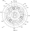
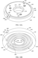
- the zero point for each turret 22, 24 is generally provided as a feature on the given turret. While FIGS. 4-10 illustrate exemplary turrets including a zero point adjustment subassembly 500 in combination with an elevation turret 22, it will be appreciated that the zero point adjustment subassembly 500 may be used with any adjustment turret, including but not limited to a windage turret or parallax adjustment mechanisms.
- the turret cap 501 sits over the turret chassis subassembly 230 and is the structure that includes the indicia 34 and, if provided, other visual and/or tactile features.
- the turret cap 501 has an upper surface 502 that defines a recess 504 (not shown) that is generally circular and centrally located on the turret cap 501.
- the recess has an upper surface 506 that is generally flat.
- An opening (not shown) runs through the center of the turret cap 501 through which the turret screw 38 protrudes.
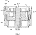
- FIG. 6 illustrates a further embodiment of a zero point adjustment subassembly 500' in accordance with embodiments of the disclosure.
- the zero cap 510' includes a lever 513' with a pivot point 513a'.
- the lever 513' has a stem 515' that projects through an opening 511' in the zero cap 510' and connects with the turret screw 38.
- the locking mechanism includes conical wedge 521' and a collet 523'.
- the conical wedge 521' is positioned around the turret screw 38 and partially extends through the opening (not shown) of the turret cap 501.
- the lock ring 530" is externally concentric to the zero cap 510" and the brake disc 527" and rotatably secured with the turret cap 501 via a threaded engagement.
- a locked position e . g ., clockwise
- the brake disc 527 transfers that downward force to the zero cap 510" that is thereby prohibited from freely spinning.
- Rotation of the lock ring 530" in the opposite direction e . g ., counterclockwise
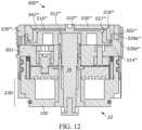
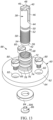
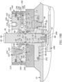
- FIGS. 10-12 illustrate a further embodiment of a zero point adjustment subassembly 500′′′ , which is a variation of subassembly 500", in accordance with embodiments of the disclosure.
- the zero point adjustment subassembly 500′′′ includes the zero cap 510′′′ and the locking mechanism 520" which is composed of the locking ring 530"', a brake disc 527′′′, and a lock ring lock button 539′′′.
- the locking ring 530′′′, brake disc 527′′′ and zero cap 510′′′ are all positioned concentrically within the recess (not shown) with the brake disc 527′′′ being externally concentric with the zero cap 510′′′ and the lock ring 530′′′ being externally concentric with both the brake disc 527 ′′′ and the zero cap 510 ′′′.
- the zero cap 510′′′ has a downward protruding stem 512 ′′′ that engages the turret screw 38.
- a flange 542 on the brake disc 527 ′′′ sits on top of at least a portion of the upper surface 516 ′′′ of the zero cap 510′′′ and retains the zero cap 510′′′ in the turret cap 501.
- the locking ring 530′′′ sits on top of a flange 518 ′′′ of the brake disc 527 ′′′ and engages the turret cap 501.
- the locking ring 530′′′ is in threaded engagement with the turret cap 501.
- the zero cap 510′′′ engages the turret screw 38 and sits in the recess (not shown) of the turret cap 501.
- the brake disc 527′′′ is circular with a central opening and sits over a flange 514′′′ of the zero cap 510′′′ in the recess.
- the brake disc 527′′′ is keyed to the turret cap 501 via the mating of projections 527a′′′ on the brake disc 527 ′′′ with recesses 501a ′′′ on the inside wall of the turret cap 501.
- the brake disc 527′′′ is therefore prohibited from rotating but is free to translate vertically.
- the lock ring 530′′′ is externally concentric to the zero cap 510′′′ and the brake disc 527′′′ and rotatably secured with the turret cap 501 via a threaded engagement.
- a locked position e . g ., clockwise
- the brake disc 527 ′′′ transfers that downward force to the zero cap 510′′′ that is thereby prohibited from freely spinning.
- Rotation of the lock ring 530′′′ in the opposite direction e . g ., counterclockwise
- the zero point adjustment subassembly 500′′′ further includes a lock ring lock button 539"'.
- the lock ring lock button 539 ′′′ includes and outer portion 539a ′′′ which, in the embodiment shown, is a portion of the turret cap 501 and includes a tactile element different from the surrounding portions of the turret cap 501.
- the lock ring lock button 539′′′ is in its locked position, meaning rotation of the lock ring 530, and therefore zero cap 510′′′ is prohibited.
- the lock ring lock button 539′′′ is provided at least one (in the embodiment shown, two) spring-containing guide-rods 539b"'.
- the lock ring 530′′′ can be freely rotated.
- the under surface of the lock ring 530′′′ will cover the button 539 ′′′ to prevent the lock ring lock button 539′′′ from returning to its locked position while a user is making adjustments.
- the springs of the spring-containing guide-rods 539b ′′′ "automatically" force the button 539′′′ back upward into the locked position once the user has rotated the lock ring 530′′′ into the rotationally locked position.
- the turret cap 501 further includes a groove 539d ′′′ and the locking ring 530′′′ further includes a corresponding protuberance 539e"'.
- the groove 539d′′′ /protuberance 539e ′′′ system limits rotation of the locking ring 530 ′′′ while the lock ring lock button 539′′′ is depressed. This ensures that the parts of the subassembly 500 ′′′ are captive in addition to limiting rotation. Since rotation is limited, the locking ring 530′′′ cannot be unthreaded and removed from the turret cap 501.
- the zero point adjustment subassemblies 500" and 500′′′ permit adjustment of the zero point without the use of tools. That is, a user can rotate the lock ring 530"/530 ′′′ and zero cap 510"/510 ′′′ by hand and similarly manipulate the other components of the subassemblies 500" and 500′′′ by hand. This saves time and does not require a user to turn away from the rifle scope to make any zero point adjustments.
- the exemplary turret chassis subassembly 400 illustrated in FIGS. 3-12 is in accordance with that disclosed in U.S. 8,919,026 which is incorporated herein by reference.
- Such an exemplary turret chassis subassembly 230 will now be described in further detail.
- the turret screw 38 is part of a turret screw subassembly 88.
- the turret screw subassembly consists of the turret screw 38, a turret screw base 60, a friction pad 86, and various fasteners.
- the turret screw 38 in the embodiment shown is a cylindrical body made of brass.
- the top 40 of the turret screw 38 defines a slot or other feature, such as threads, 40 that engage the zero point adjustment subassembly 500 (not shown).
- Two opposing cam slots 46 run from the top part way down the side 44.
- Two o-ring grooves 50 and 52 are on the side located below the cam slots.
- the bottom 42 of the turret screw has a reduced radius portion 56 that defines a ring slot 54.
- the ring slot 54 receives a retaining ring 84, and a bore 304 in the bottom receives the shaft 306 of the friction pad 86.
- the side of the turret screw immediately below the o-ring groove 52 and above the ring slot 54 is a threaded portion 58.
- the turret screw base 60 is a disc-shaped body that may also be made of brass.
- a cylindrical collar 66 rises from the center to the top 62 of the turret screw base.
- the collar has a turret screw bore 68 with threads 70.
- the exterior of the collar defines a set screw V-groove 78 above the top of the turret screw base, an o-ring groove 74 above the o-ring groove 76, and a ring slot 72 above the o-ring groove 74.
- the turret screw base 60 has three mount holes 82 with smooth sides and a shoulder that receives screws 80.
- the fitting of the turret screw subassembly 88 to the turret housing 36 is shown in FIG. 14 .
- the top 92 of the turret housing defines a recess 94.
- Three mount holes 96 with threads 98 and a smooth central bore 508 are defined in the top of the turret housing within the recess.
- the threads 70 of the turret screw bore 68 are such that the turret screw bore may receive the threads 58 on the turret screw 38.
- the retaining ring 84 limits upward travel of the turret screw 38 so that the turret screw 38 cannot be inadvertently removed from the turret screw bore.
- the turret screw subassembly 88 When the turret screw subassembly 88 is mounted on the turret housing 36, screws 80 are inserted into the mount holes 82 and protrude from the bottom 64 of the turret screw base. The screws are then screwed into the mount holes 96 in the turret housing. Subsequently, the turret screw base remains in a fixed position with respect to the scope body 12 when the elevation turret 22 is rotated. This essentially makes the turret screw base functionally unitary with the scope body, and the turret screw base is not intended to be removed or adjusted by the user.
- the smooth central bore 508 in the top of the turret housing permits passage of the friction pad 86 and the bottom 42 of the turret screw 38 into the scope body 12.
- the top 110 of the turret chassis 100 has an interior perimeter 102 with a relief cut 240 adjacent to the floor 264, a toothed surface 108 above the relief cut, a lower click groove 106 above the toothed surface 108, and an upper click groove 104 above the lower click groove 106.
- the relieve cut 240 is for the tool that cuts the toothed surface 108.
- the floor defines a smooth central bore 120 and a slot 122.
- the smooth central bore 120 permits passage of the friction pad 86 and the bottom 42 of the turret screw 38 through the turret chassis 100.
- the exterior perimeter 112 of the turret chassis 100 defines an o-ring groove 244. Near the bottom 116 of the turret chassis, the exterior perimeter widens to define a shoulder 114. Three holes 118 with threads 158 communicate from the exterior perimeter through the turret chassis to the smooth bore 120.
- the turret chassis 100 is made of steel.
- the slot 122 in the floor 264 of the turret chassis 100 communicates with a hole 124 in the exterior perimeter 112 of the turret chassis 100.
- the hole 124 receives an indicator, such as an elevation indicator 136.
- the rear 140 of the indicator 136 defines a cam pin hole 154.
- the front 138 of the indicator 136 has two stripes 148 and 150 and an o-ring groove 152.
- the stripe 148 divides a first position 142 from a second position 144.
- the stripe 150 divides a second position 144 from a third position 146.
- the elevation indicator 136 is made of painted black steel and the stripes are white lines that do not glow, but which could be luminous in an alternative embodiment.
- the locking gear 206 has a top 208 and a bottom 210.
- the top 208 defines three mount holes 216 with threads 218.
- the locking gear 206 also defines three smooth mount holes 220 and a central smooth bore 222.
- the bottom 210 of the locking gear 206 defines a toothed surface 214.
- the toothed surface 214 extends downward below the bottom 210 of the locking gear 206 to encircle the reduced radius portion 166 of the top 162 of the cam disc 160 when the chassis subassembly 230 is assembled.
- the toothed surface 214 has 100 teeth to mesh precisely with the 100 teeth of the toothed surface 108 on the interior perimeter 102 of the turret chassis 100 when the elevation turret 22 is locked.
- ball bearings 226 protrude outwards from bores 232 in the exterior perimeter 212 located between the toothed surface and the top.
- Springs 400 located behind the ball bearings outwardly bias the ball bearings such that the ball bearings are biased to engage with the upper click groove 104 and lower click groove 106 on the interior perimeter 102 of the turret chassis 100.
- the ball bearings 226 travel between the lower and upper click grooves 104, 106, thereby providing a vertical, resistant force and making a characteristic clicking sound.
- the locking gear 206 is free to be raised until the heads 234 of the screws 224 contact the shoulders 236 and to be lowered until the bottom of the locking gear 206 contacts the top 162 of the cam disc 160.
- This vertical movement is sufficient for the toothed surface 214 of the locking gear 206 to be raised above the toothed surface 108 of the turret chassis 100, thereby enabling the elevation 22 turret to be unlocked and free to rotate.
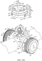
- FIGS. 19A and 19B illustrate the turret chassis subassembly 230, screw subassembly 88, and turret housing 36. More particularly, the turret chassis subassembly 230 is shown assembled and in the process of being mounted on the turret screw subassembly 88 in FIG. 19A and mounted on the turret screw subassembly in FIG. 19B .
- Three recesses 245 in the bottom 116 of the turret chassis 100 receive the heads of the screws 80 that protrude from the top 62 of the turret screw base 60 so the bottom 116 of the turret chassis 100 can sit flush against the top 92 of the turret housing 36.
- turret chassis subassembly 230 is described above with respect to a turret, which is an elevation turret, one of skill in the art will appreciate that similar designs may be used for turrets that make other adjustments, such as windage turrets. Further, the turret chassis subassembly 230 described above is described with respect to a zero point adjustment subassembly in accordance with embodiment 500. It will be appreciated that the turret chassis subassemblies 230 described herein can be implemented with any embodiment of the zero point adjustment subassembly 500, 500', 500", 500 ′′′ or combination of embodiments described herein.
Landscapes
- Physics & Mathematics (AREA)
- Optics & Photonics (AREA)
- General Physics & Mathematics (AREA)
- Astronomy & Astrophysics (AREA)
- Engineering & Computer Science (AREA)
- General Engineering & Computer Science (AREA)
- Aiming, Guidance, Guns With A Light Source, Armor, Camouflage, And Targets (AREA)
- Telescopes (AREA)
- Mechanical Control Devices (AREA)
Applications Claiming Priority (3)
| Application Number | Priority Date | Filing Date | Title |
|---|---|---|---|
| US201962789769P | 2019-01-08 | 2019-01-08 | |
| EP20738510.5A EP3908871B1 (de) | 2019-01-08 | 2020-01-07 | Zielfernrohrturm mit werkzeugloser nullsetzung |
| PCT/US2020/012580 WO2020146385A2 (en) | 2019-01-08 | 2020-01-07 | Rifle scope turret with tool-free zeroing |
Related Parent Applications (1)
| Application Number | Title | Priority Date | Filing Date |
|---|---|---|---|
| EP20738510.5A Division EP3908871B1 (de) | 2019-01-08 | 2020-01-07 | Zielfernrohrturm mit werkzeugloser nullsetzung |
Publications (2)
| Publication Number | Publication Date |
|---|---|
| EP4538764A2 true EP4538764A2 (de) | 2025-04-16 |
| EP4538764A3 EP4538764A3 (de) | 2025-07-30 |
Family
ID=71520890
Family Applications (2)
| Application Number | Title | Priority Date | Filing Date |
|---|---|---|---|
| EP20738510.5A Active EP3908871B1 (de) | 2019-01-08 | 2020-01-07 | Zielfernrohrturm mit werkzeugloser nullsetzung |
| EP25161528.2A Pending EP4538764A3 (de) | 2019-01-08 | 2020-01-07 | Gewehrzielturm mit werkzeugloser nullstellung |
Family Applications Before (1)
| Application Number | Title | Priority Date | Filing Date |
|---|---|---|---|
| EP20738510.5A Active EP3908871B1 (de) | 2019-01-08 | 2020-01-07 | Zielfernrohrturm mit werkzeugloser nullsetzung |
Country Status (9)
| Country | Link |
|---|---|
| US (3) | US11320241B2 (de) |
| EP (2) | EP3908871B1 (de) |
| JP (2) | JP7655852B2 (de) |
| CN (2) | CN119492289A (de) |
| AU (3) | AU2020205633A1 (de) |
| CA (1) | CA3126257A1 (de) |
| PH (1) | PH12021551628A1 (de) |
| WO (1) | WO2020146385A2 (de) |
| ZA (1) | ZA202105750B (de) |
Families Citing this family (17)
| Publication number | Priority date | Publication date | Assignee | Title |
|---|---|---|---|---|
| US9170068B2 (en) * | 2012-01-04 | 2015-10-27 | Leupold & Stevens, Inc. | Locking adjustment device |
| GB201900665D0 (en) * | 2019-01-17 | 2019-03-06 | Deben Group Industries Ltd | 06557607002 |
| US11530899B2 (en) * | 2019-01-18 | 2022-12-20 | Primary Arms, Llc | Locking adjustment assembly and method for an optical aiming device |
| US12429306B2 (en) * | 2019-02-27 | 2025-09-30 | Leupold & Stevens, Inc. | Engagement lock for tool-less re-zero adjustment knob |
| US11243049B1 (en) | 2019-02-27 | 2022-02-08 | Leupold & Stevens, Inc. | Tool-less re-zero optical scope knob adjustment systems and methods |
| US11906268B2 (en) | 2019-02-27 | 2024-02-20 | Leupold & Stevens, Inc. | Tool-less re-zero adjustment knob for aiming devices, and methods of zeroing an aiming device |
| CA3168232A1 (en) * | 2020-01-15 | 2021-07-22 | Sheltered Wings, Inc. D/B/A Vortex Optics | Viewing optic with contours |
| CN114076585A (zh) * | 2020-08-18 | 2022-02-22 | 信泰光学(深圳)有限公司 | 测距补偿装置 |
| CN111964530B (zh) * | 2020-08-28 | 2025-04-18 | 武汉高明兰光电科技有限公司 | 一种具有零位限位功能的调节手轮组及瞄准镜 |
| USD969261S1 (en) * | 2021-01-18 | 2022-11-08 | Xinjian Guo | Telescope |
| CN115507701B (zh) | 2021-06-23 | 2024-04-23 | 信泰光学(深圳)有限公司 | 补正机构 |
| AU2022358499A1 (en) | 2021-09-28 | 2024-05-09 | Sheltered Wings, Inc. D/B/A Vortex Optics | Scope turret |
| US20230314101A1 (en) * | 2022-03-29 | 2023-10-05 | Sheltered Wings, Inc. D/B/A Vortex Optics | Protective cover with alignment aperture |
| JP7670365B2 (ja) | 2023-02-16 | 2025-04-30 | 有限会社 ディオン光学技研 | ダイヤル式調整装置 |
| WO2024186547A1 (en) | 2023-03-06 | 2024-09-12 | Leupold & Stevens, Inc. | Toolless knob assembly for optical device |
| US12235076B2 (en) * | 2023-04-28 | 2025-02-25 | Leupold & Stevens, Inc. | Locking adjustment device |
| US12305959B1 (en) * | 2025-01-13 | 2025-05-20 | Leapers, Inc. | Modifiable turret for optical scope |
Citations (1)
| Publication number | Priority date | Publication date | Assignee | Title |
|---|---|---|---|---|
| US8919026B2 (en) | 2012-04-18 | 2014-12-30 | Sheltered Wings, Inc. | Rifle scope turret with spiral cam mechanism |
Family Cites Families (39)
| Publication number | Priority date | Publication date | Assignee | Title |
|---|---|---|---|---|
| GB178236A (en) * | 1921-01-29 | 1922-04-20 | Harry Reginald Leycester Ether | Improvements in orthoptic rear sights for rifles and like small arms |
| GB780136A (en) * | 1954-07-02 | 1957-07-31 | Daniel Robertson | Improvements in or relating to rifle rear sights |
| US2811894A (en) * | 1954-12-31 | 1957-11-05 | Benjamin V B Braker | Telescopic sight for direct fire gunnery |
| US3095750A (en) * | 1959-12-12 | 1963-07-02 | Optische Werke Jos Schneider & | Control mechanism for the axial displacement of components of photographic or cinematographic objectives and the like |
| JPS50122209A (de) * | 1974-02-18 | 1975-09-25 | ||
| DE3823714C2 (de) * | 1987-07-13 | 1999-11-04 | Olympus Optical Co | Vorrichtung zum stufenlosen Verstellen der Brennweite eines Zoomobjektivs |
| JP2915929B2 (ja) * | 1989-07-11 | 1999-07-05 | 旭光学工業株式会社 | カメラのレンズ駆動装置 |
| FR2753563B1 (fr) * | 1996-09-16 | 1998-10-16 | Schneider Electric Sa | Interrupteur electrique multipolaire ayant un barreau de commutation elementaire par pole |
| US6351907B1 (en) * | 1999-01-29 | 2002-03-05 | Leupold & Stevens, Inc. | Spiral cam mechanism for rifle sight adjustment |
| AT413884B (de) * | 2004-08-18 | 2006-07-15 | Kahles Ges M B H | Betätigungselement für ein zielfernrohr |
| EP1817538B1 (de) * | 2004-11-30 | 2013-03-27 | Bernard Thomas Windauer | Optisches visiersystem |
| US8267901B2 (en) * | 2007-09-25 | 2012-09-18 | Claus Schmidt Moller | Dose delivery device with gearing mechanism |
| USRE46011E1 (en) * | 2008-01-31 | 2016-05-24 | Lightforce Usa, Inc. | Locking adjustment dial mechanism for riflescope |
| US8104217B2 (en) * | 2008-01-31 | 2012-01-31 | Lightforce Usa, Inc. | Riflescope high speed adjusting elevation assembly |
| CN101236076B (zh) * | 2008-02-29 | 2010-10-27 | 成都工具研究所 | 带有标准角度转台的激光角度干涉测量系统及其测量方法 |
| US7908782B1 (en) * | 2008-04-12 | 2011-03-22 | Larue Mark C | Pivot mount for firearm sighting devices |
| EP2304377A2 (de) * | 2008-06-22 | 2011-04-06 | Bernard Thomas Windauer | Drehknopf für einen vom bediener wählbaren stopp |
| US8312667B2 (en) * | 2009-01-14 | 2012-11-20 | Premier Reticles, Ltd | Lockable adjustment mechanism |
| CN102472604B (zh) * | 2009-08-20 | 2014-11-12 | 克鲁格光学有限公司 | 双模式的反射式和望远镜式瞄准器组合 |
| US8166696B2 (en) * | 2009-09-14 | 2012-05-01 | Sheltered Wings, Inc. | Rifle scope with adjustment stop |
| US9188408B2 (en) * | 2009-11-04 | 2015-11-17 | Leupold & Stevens, Inc. | Auto-locking adjustment device |
| US8490317B2 (en) * | 2010-12-30 | 2013-07-23 | Trijicon, Inc. | Locking turret |
| US9170068B2 (en) * | 2012-01-04 | 2015-10-27 | Leupold & Stevens, Inc. | Locking adjustment device |
| US8904696B2 (en) * | 2012-03-06 | 2014-12-09 | Leica Camera Ag | Device for fast reticle adjustment of a sighting device |
| US9677848B2 (en) * | 2012-04-18 | 2017-06-13 | Sheltered Wings, Inc. | Multiple knob turret |
| US8806798B2 (en) * | 2012-11-21 | 2014-08-19 | Leupold & Stevens, Inc. | Riflescope adjustment knob with interchangeable adjustment indicator ring |
| US9182773B2 (en) * | 2013-01-14 | 2015-11-10 | Leupold & Stevens, Inc. | Low profile auto-locking pinch/turn adjustment knob |
| JP2016533220A (ja) * | 2013-10-16 | 2016-10-27 | ノボ・ノルデイスク・エー/エス | 改善された投与量リセット機構を有する薬物送達デバイス |
| GB2524348A (en) * | 2014-09-29 | 2015-09-23 | Deben Group Ind Ltd | Telescopic sight |
| CN105988210B (zh) * | 2015-02-06 | 2019-01-11 | 信泰光学(深圳)有限公司 | 瞄准器 |
| CN105953649B (zh) * | 2015-12-11 | 2018-01-12 | 江苏优特集体育器材制造有限公司 | 一种调节手轮 |
| US10302394B2 (en) * | 2016-01-13 | 2019-05-28 | Leapers, Inc. | Turret locking mechanism for optical device |
| CN108779970B (zh) | 2016-01-27 | 2021-12-21 | 夏尔特银斯公司D.B.A.涡流光学 | 具有零点止动件的调整钮 |
| CN205373522U (zh) * | 2016-01-29 | 2016-07-06 | 南通德尔塔光学有限公司 | 一种瞄准镜的弹道调节装置 |
| GB2547935B (en) * | 2016-03-03 | 2019-05-29 | Mtc Optics Ltd | Elevation adjustment turret for weapon sight |
| CA3023558C (en) * | 2016-05-13 | 2020-01-21 | Vista Outdoor Operations Llc | Adjustable zero-stop turret |
| US10054398B2 (en) * | 2016-11-02 | 2018-08-21 | Burris Company, Inc. | Optical device knob having variable resistance to rotation |
| CN107481289B (zh) * | 2017-07-13 | 2020-07-03 | 西安应用光学研究所 | 大视场相机远场标校的精密靶标系统及方法 |
| CN108759564A (zh) * | 2018-08-24 | 2018-11-06 | 珠海天羿精密仪器有限公司 | 一种枪瞄调节器归零装置 |
-
2020
- 2020-01-07 EP EP20738510.5A patent/EP3908871B1/de active Active
- 2020-01-07 CN CN202411625136.1A patent/CN119492289A/zh active Pending
- 2020-01-07 CA CA3126257A patent/CA3126257A1/en active Pending
- 2020-01-07 WO PCT/US2020/012580 patent/WO2020146385A2/en not_active Ceased
- 2020-01-07 US US16/736,440 patent/US11320241B2/en active Active
- 2020-01-07 PH PH1/2021/551628A patent/PH12021551628A1/en unknown
- 2020-01-07 EP EP25161528.2A patent/EP4538764A3/de active Pending
- 2020-01-07 CN CN202080019409.1A patent/CN113966480B/zh active Active
- 2020-01-07 AU AU2020205633A patent/AU2020205633A1/en not_active Abandoned
- 2020-01-07 JP JP2021539944A patent/JP7655852B2/ja active Active
-
2021
- 2021-08-04 ZA ZA2021/05750A patent/ZA202105750B/en unknown
-
2022
- 2022-05-02 US US17/734,831 patent/US12209842B2/en active Active
-
2023
- 2023-09-26 AU AU2023237045A patent/AU2023237045A1/en not_active Abandoned
-
2025
- 2025-01-27 US US19/037,994 patent/US20250189269A1/en active Pending
- 2025-03-21 JP JP2025046381A patent/JP2025105609A/ja active Pending
- 2025-07-31 AU AU2025210830A patent/AU2025210830A1/en active Pending
Patent Citations (1)
| Publication number | Priority date | Publication date | Assignee | Title |
|---|---|---|---|---|
| US8919026B2 (en) | 2012-04-18 | 2014-12-30 | Sheltered Wings, Inc. | Rifle scope turret with spiral cam mechanism |
Also Published As
| Publication number | Publication date |
|---|---|
| EP3908871A2 (de) | 2021-11-17 |
| WO2020146385A8 (en) | 2021-12-09 |
| PH12021551628A1 (en) | 2022-06-06 |
| AU2023237045A1 (en) | 2023-10-12 |
| CA3126257A1 (en) | 2020-07-16 |
| US12209842B2 (en) | 2025-01-28 |
| WO2020146385A2 (en) | 2020-07-16 |
| US11320241B2 (en) | 2022-05-03 |
| AU2025210830A1 (en) | 2025-08-21 |
| CN113966480A (zh) | 2022-01-21 |
| US20200326155A1 (en) | 2020-10-15 |
| JP2025105609A (ja) | 2025-07-10 |
| WO2020146385A9 (en) | 2020-08-13 |
| AU2020205633A1 (en) | 2021-08-26 |
| EP4538764A3 (de) | 2025-07-30 |
| US20230113722A1 (en) | 2023-04-13 |
| US20250189269A1 (en) | 2025-06-12 |
| EP3908871B1 (de) | 2025-03-05 |
| WO2020146385A3 (en) | 2021-05-14 |
| EP3908871A4 (de) | 2022-09-21 |
| JP7655852B2 (ja) | 2025-04-02 |
| CN119492289A (zh) | 2025-02-21 |
| CN113966480B (zh) | 2024-12-03 |
| JP2022516980A (ja) | 2022-03-03 |
| ZA202105750B (en) | 2022-08-31 |
Similar Documents
| Publication | Publication Date | Title |
|---|---|---|
| US12209842B2 (en) | Rifle scope turret with tool-free zeroing | |
| US11940243B2 (en) | Scope turret | |
| US11971241B2 (en) | Self-centering guide rod system for a rifle scope turret | |
| US8166696B2 (en) | Rifle scope with adjustment stop | |
| US12578167B2 (en) | Scope turret |
Legal Events
| Date | Code | Title | Description |
|---|---|---|---|
| PUAI | Public reference made under article 153(3) epc to a published international application that has entered the european phase |
Free format text: ORIGINAL CODE: 0009012 |
|
| STAA | Information on the status of an ep patent application or granted ep patent |
Free format text: STATUS: THE APPLICATION HAS BEEN PUBLISHED |
|
| AC | Divisional application: reference to earlier application |
Ref document number: 3908871 Country of ref document: EP Kind code of ref document: P |
|
| AK | Designated contracting states |
Kind code of ref document: A2 Designated state(s): AL AT BE BG CH CY CZ DE DK EE ES FI FR GB GR HR HU IE IS IT LI LT LU LV MC MK MT NL NO PL PT RO RS SE SI SK SM TR |
|
| REG | Reference to a national code |
Ref country code: DE Ref legal event code: R079 Free format text: PREVIOUS MAIN CLASS: G02B0007000000 Ipc: G02B0007020000 |
|
| PUAL | Search report despatched |
Free format text: ORIGINAL CODE: 0009013 |
|
| AK | Designated contracting states |
Kind code of ref document: A3 Designated state(s): AL AT BE BG CH CY CZ DE DK EE ES FI FR GB GR HR HU IE IS IT LI LT LU LV MC MK MT NL NO PL PT RO RS SE SI SK SM TR |
|
| RIC1 | Information provided on ipc code assigned before grant |
Ipc: G02B 7/02 20210101AFI20250623BHEP Ipc: F41G 1/16 20060101ALI20250623BHEP Ipc: F41G 1/38 20060101ALI20250623BHEP Ipc: F41G 1/28 20060101ALI20250623BHEP Ipc: G02B 23/14 20060101ALI20250623BHEP Ipc: G02B 23/16 20060101ALI20250623BHEP Ipc: G02B 7/00 20210101ALI20250623BHEP |
|
| STAA | Information on the status of an ep patent application or granted ep patent |
Free format text: STATUS: REQUEST FOR EXAMINATION WAS MADE |
|
| 17P | Request for examination filed |
Effective date: 20260130 |