EP4538758A2 - Hohlkern-lichtleitfaser - Google Patents
Hohlkern-lichtleitfaser Download PDFInfo
- Publication number
- EP4538758A2 EP4538758A2 EP25160718.0A EP25160718A EP4538758A2 EP 4538758 A2 EP4538758 A2 EP 4538758A2 EP 25160718 A EP25160718 A EP 25160718A EP 4538758 A2 EP4538758 A2 EP 4538758A2
- Authority
- EP
- European Patent Office
- Prior art keywords
- primary
- capillaries
- hollow core
- capillary
- optical fibre
- Prior art date
- Legal status (The legal status is an assumption and is not a legal conclusion. Google has not performed a legal analysis and makes no representation as to the accuracy of the status listed.)
- Pending
Links
Images




Classifications
-
- G—PHYSICS
- G02—OPTICS
- G02B—OPTICAL ELEMENTS, SYSTEMS OR APPARATUS
- G02B6/00—Light guides; Structural details of arrangements comprising light guides and other optical elements, e.g. couplings
- G02B6/02—Optical fibres with cladding with or without a coating
- G02B6/02295—Microstructured optical fibre
- G02B6/023—Microstructured optical fibre having different index layers arranged around the core for guiding light by reflection, i.e. 1D crystal, e.g. omniguide
- G02B6/02304—Core having lower refractive index than cladding, e.g. air filled, hollow core
-
- G—PHYSICS
- G02—OPTICS
- G02B—OPTICAL ELEMENTS, SYSTEMS OR APPARATUS
- G02B6/00—Light guides; Structural details of arrangements comprising light guides and other optical elements, e.g. couplings
- G02B6/02—Optical fibres with cladding with or without a coating
- G02B6/032—Optical fibres with cladding with or without a coating with non solid core or cladding
-
- C—CHEMISTRY; METALLURGY
- C03—GLASS; MINERAL OR SLAG WOOL
- C03B—MANUFACTURE, SHAPING, OR SUPPLEMENTARY PROCESSES
- C03B37/00—Manufacture or treatment of flakes, fibres, or filaments from softened glass, minerals, or slags
- C03B37/01—Manufacture of glass fibres or filaments
- C03B37/02—Manufacture of glass fibres or filaments by drawing or extruding, e.g. direct drawing of molten glass from nozzles; Cooling fins therefor
- C03B37/025—Manufacture of glass fibres or filaments by drawing or extruding, e.g. direct drawing of molten glass from nozzles; Cooling fins therefor from reheated softened tubes, rods, fibres or filaments, e.g. drawing fibres from preforms
- C03B37/027—Fibres composed of different sorts of glass, e.g. glass optical fibres
- C03B37/02781—Hollow fibres, e.g. holey fibres
-
- G—PHYSICS
- G02—OPTICS
- G02B—OPTICAL ELEMENTS, SYSTEMS OR APPARATUS
- G02B6/00—Light guides; Structural details of arrangements comprising light guides and other optical elements, e.g. couplings
- G02B6/02—Optical fibres with cladding with or without a coating
- G02B6/02042—Multicore optical fibres
-
- G—PHYSICS
- G02—OPTICS
- G02B—OPTICAL ELEMENTS, SYSTEMS OR APPARATUS
- G02B6/00—Light guides; Structural details of arrangements comprising light guides and other optical elements, e.g. couplings
- G02B6/02—Optical fibres with cladding with or without a coating
- G02B6/02295—Microstructured optical fibre
- G02B6/02314—Plurality of longitudinal structures extending along optical fibre axis, e.g. holes
- G02B6/02319—Plurality of longitudinal structures extending along optical fibre axis, e.g. holes characterised by core or core-cladding interface features
- G02B6/02323—Core having lower refractive index than cladding, e.g. photonic band gap guiding
- G02B6/02328—Hollow or gas filled core
-
- G—PHYSICS
- G02—OPTICS
- G02B—OPTICAL ELEMENTS, SYSTEMS OR APPARATUS
- G02B6/00—Light guides; Structural details of arrangements comprising light guides and other optical elements, e.g. couplings
- G02B6/02—Optical fibres with cladding with or without a coating
- G02B6/02295—Microstructured optical fibre
- G02B6/02314—Plurality of longitudinal structures extending along optical fibre axis, e.g. holes
- G02B6/02342—Plurality of longitudinal structures extending along optical fibre axis, e.g. holes characterised by cladding features, i.e. light confining region
-
- G—PHYSICS
- G02—OPTICS
- G02B—OPTICAL ELEMENTS, SYSTEMS OR APPARATUS
- G02B6/00—Light guides; Structural details of arrangements comprising light guides and other optical elements, e.g. couplings
- G02B6/02—Optical fibres with cladding with or without a coating
- G02B6/02295—Microstructured optical fibre
- G02B6/02314—Plurality of longitudinal structures extending along optical fibre axis, e.g. holes
- G02B6/02342—Plurality of longitudinal structures extending along optical fibre axis, e.g. holes characterised by cladding features, i.e. light confining region
- G02B6/02357—Property of longitudinal structures or background material varies radially and/or azimuthally in the cladding, e.g. size, spacing, periodicity, shape, refractive index, graded index, quasiperiodic, quasicrystals
-
- C—CHEMISTRY; METALLURGY
- C03—GLASS; MINERAL OR SLAG WOOL
- C03B—MANUFACTURE, SHAPING, OR SUPPLEMENTARY PROCESSES
- C03B2203/00—Fibre product details, e.g. structure, shape
- C03B2203/10—Internal structure or shape details
- C03B2203/14—Non-solid, i.e. hollow products, e.g. hollow clad or with core-clad interface
- C03B2203/16—Hollow core
Definitions
- Classes of optical fibre include hollow core fibres, in which light is guided along a longitudinal hollow void forming the fibre's core by an optical guidance mechanism enabled by the presence of a structured arrangement of longitudinal cladding capillaries surrounding the void.
- Various configurations for the cladding capillaries are known, producing different guidance mechanisms.
- An example is hollow core photonic bandgap fibre (HCPBF, alternatively hollow core photonic crystal fibres, HCPCF), in which the cladding comprises a regular closely packed array of many small glass capillaries from which a central group is excluded to define a substantially circular hollow core.
- the periodicity of the cladding capillary structure provides a periodically structured refractive index and hence a photonic bandgap effect that confines a propagating optical wave within the core.
- a preform or a cane for making a hollow core optical fibre which is configured to be drawn into a hollow core optical fibre according to the first aspect.
- Figure 1(B) shows a transverse cross-sectional view of a second previously-proposed antiresonant hollow core fibre [2, 3].
- the fibre includes all the features of the Figure 1(A) example, but the cladding has a more complex structure
- Each cladding capillary 14 is a primary capillary, still spaced from its neighbour by a gap d, and has a secondary, smaller capillary 20 nested inside it, bonded to the inner surface of the cladding capillary 14 at the same azimuthal position around the jacket 12 as the point of bonding 16 between the primary capillary 14 and the jacket 12.
- These additional smaller capillaries 20 are included with the aim of reducing the optical loss in the fibre.
- the example cladding structures shown in Figures 1(A) and 1(B) comprise six primary cladding capillaries arranged in a ring around the core.
- ARFs are not so limited however, and may instead comprises five or fewer or seven or more capillaries forming the boundary around the hollow core. This is true of these previously-proposed examples, and of ARFs according to the present disclosure which are described below.
- Figure 2 shows a transverse cross-sectional view of another previously proposed antiresonant hollow core fibre structure [4].
- the fibre comprises six primary capillaries 14 bonded at positions 16 at regular intervals around the inner surface of an outer tubular jacket 12, and spaced apart from one another.
- Inside each primary capillary there are three secondary capillaries 20, each bonded to the inner surface of the respective primary capillary 14.
- a first secondary capillary 20a is bonded in line with the contact point 16 between the jacket 12 and the primary capillary 14.
- the other two secondary capillaries 20b are arranged one on each side of the first secondary capillary 20a and spaced apart from the first secondary capillary 20a by an angle of 90°, measured as an azimuthal position around the circumference of the primary capillary 14.
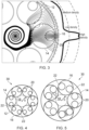
- Figure 3 shows a transverse cross-sectional view of part of an ARF with a previously-proposed 6-cell NANF cladding structure (as described above with reference to Figure 1(B) ).
- black lines obtained from modelling the flow of optical power in the transverse plane, by tracing flow lines of the transverse Poynting vector.
- Optical power flowing radially outwards from the core to the outer surface of the cladding is power which is lost from the desired forward direction of propagation of power along the length of the fibre's core, and hence contributes to the level of optical loss in the fibre.
- the black lines are streamlines that follow the transverse power flow vector fields, which are seeded in the centre of the core and spiral outwards towards the cladding tubes.
- the curve shown to the right of the fibre plots the total transversely leaked optical power, for each position around the circumference of the fibre (fibre boundary).
- the height of the curve measured from the depicted outer surface of the fibre corresponds to the density of the power flow lines at the fibre-air boundary.
- the inventors have identified that the main source of radial light leakage, which tends to be the dominant optical loss mechanism in ARFs, is not the gaps between the spaced-apart primary capillaries. This is contrary to the general understanding of these fibres, in which the gaps are typically minimised to reduce loss. Rather, these parts of the cladding structure contribute only a small part in the overall loss, and instead the principal loss of power arises at the regions in line with the nested capillaries, at the azimuthal positions around the jacket where the secondary capillaries are bonded inside the primary capillaries which are bonded inside the jacket.
- the present disclosure proposes a new geometry or design of nested cladding capillaries for ARFs which introduces more of the newly-identified leakage-reducing low loss features, while removing the high leakage features, namely the radial alignment of the nested capillaries.
- the simplicity of known ARF designs is preserved, together with the associated relative ease of fabrication. Structures in accordance with the disclosure show vastly superior performance in terms of reduced optical power loss.
- Figure 4 shows a transverse cross-sectional view of a first example hollow core fibre according to the present disclosure.
- the fibre 30 comprises an hollow tubular outer jacket 12.
- a series of six primary capillaries 14 are arranged in a ring around the inner surface of the jacket 12.
- the primary capillaries 14 in this example each have the same size and circular shape, and are each bonded, secured or fixed to the inner surface of the jacket 12 at a different azimuthal position 16 around the circumference of the jacket 12 so that the primary capillaries 14 are evenly spaced around the ring.
- the primary capillaries 14 are each spaced apart from the two adjacent capillaries, so that there are gaps between adjacent capillaries, each gap being substantially the same width since the primary capillaries 14 have the same size and shape.
- a line joining the two contact points 22 of the secondary capillaries 20 to the primary capillary 14 is orthogonal to the radius from the core centre to the contact point 16 of the primary capillary 14 to the jacket 12.
- the displacement in this example is 90°.
- the line joining the two contact points 22 lies along a diameter of the primary capillary 14 which is orthogonal to the radius from the core centre to the contact point 16.
- the radii of the primary capillary which join the primary capillary centre to each of the contact points 22 lie along this same diameter.
- each primary capillary has two, and only two (that is, not one and not more than two, in other words more than one and fewer than three) secondary capillaries.
- Figure 6 shows a transverse cross-sectional view of part of an ARF according to the present disclosure and structured with six primary capillaries as in the Figure 4 example, with superimposed lines obtained from modelling the flow of optical power in the transverse plane, similar to the modelling results shown in Figure 3 for the previously-proposed 6-cell NANF cladding structure.
- the parameters used for the simulation are the same as those used to produce the results shown in Figure 3 , the only difference being the cladding structure with two spaced-apart secondary capillaries 20 inside each primary capillary 14.
- a curve representing the amount of transverse power leakage is plotted on the same scale as the curve in Figure 3 , as indicated by the dashed lines.
- the gaps between the two secondary capillaries 20 in each primary capillary and the gaps between two adjacent primary capillaries 14 are the same size.
- the gaps are selected to have a size of 5T, where T is the thickness of the walls of the primary capillaries and the walls of the secondary capillaries (selected in these examples to be the same).
- the core radius R may be 15 ⁇ m and the wall thickness t may be 0.55 ⁇ m.
- these dimensions are suitable for a fibre designed for guiding light at a wavelength of substantially 1550 nm, which is a standard or common wavelength used in optical telecommunications applications, owing to its minimal loss in silicon, from which conventional solid core telecommunications optical fibre is made. Accordingly, the core radius is equal to about 10 wavelengths, and the capillary wall thickness is equal to about 0.35 wavelengths. While these values are for example only, the various simulations, models and data discussed below have been obtained for fibres with these dimensions. The results are presented with the geometric or dimensional parameters normalised to wavelength, however, so that they can be scaled for use in the design of fibres for guiding other wavelengths.
- the reduced number of primary capillaries allows for more space in the cladding structure (a larger value of the width z can be achieved) which gives greater suppression of higher order optical modes, and superior confinement and reduced impact from resonances.
- the improvement in optical confinement loss compared to the NANF is close to 450 times.
- the five cell configuration is also easier to fabricate since it comprises fewer glass elements.
- Fabrication of hollow core fibres with structured claddings formed from capillaries typically includes pressurisation of the various spaces within the tubes to achieve and maintain the intended cross-sectional structure during drawing of the fibre from a preform or a cane, and the same number of pressurisation regions or zones are needed for the new design as for the NANF.
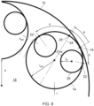
- the secondary capillaries 20 have an internal radius r in , being the distance from the central longitudinal axis of the secondary capillary to the inner surface of the primary capillary.
- the primary capillaries 14 are substantially evenly positioned around the jacket circumference, with a spacing d out between each adjacent pair of primary capillaries, being the distance between the two closest points of the outer surfaces of the adjacent primary capillaries.
- the two secondary capillaries 20 are spaced apart by a spacing d nest , being the distance between the two closest points on the outer surfaces of the secondary capillaries.
- Each primary capillary 14 is bonded to the jacket 12 at a contact point 16, each contact point 16 at a different azimuthal position around the circumference or periphery of the jacket 12, and regularly spaced.
- each primary capillary 14 the two secondary capillaries 20 are each bonded to the inner surface of the primary capillary at a contact point 22, the two contact points at a different azimuthal position around the circumference of the outer capillary 14.
- Neither contact point 22 is coincident with the contact point 16 between the primary capillary 14 and the jacket 12.
- the contact point 16 of each primary capillary can be considered to have a peripheral location or position around the jacket
- the contact point 22 of each secondary capillary can be considered to have an azimuthal location or position around the primary capillary, where the azimuthal locations are each displaced or separated from the peripheral location, in other words, neither azimuthal position coincides with the peripheral location.
- Modelling of the performance of fibres configured in accordance with the present disclosure enables the identification of ranges for the various geometric parameters which are able to deliver particularly good performance as regards optical loss of a fibre.
- simulations have been carried out using representative dimensions which are appropriate for waveguiding of the standard telecommunications wavelength of 1550 nm, namely a core radius R of 15 ⁇ m and a capillary wall thickness T of 0.55 ⁇ m, with the geometric dimensions then normalised to wavelength to allow scaling for the fabrication of fibres to guide alternate wavelengths of light.
- r in r out ⁇ T sin ⁇ n ⁇ d nest 2 + T 1 + sin ⁇ with the parameters defined as before.
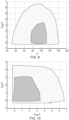
- ⁇ at or near to 90° are particularly beneficial in achieving very low loss.
- ⁇ may be substantially 90°, or may be in the range of 85° to 95°
- the ranges may be preferred to be >0 to 4.5 for d out / ⁇ and >0 to 6.7 for d nest / ⁇ .
- the specification of the lower limits of theses range as ">0" indicates that the capillaries should be arranged so as not to be in contact, i.e. the gap or spacing between them has a finite positive value.
- Figure 11 shows a graph of the amount of confinement loss in dB/km as the misalignment varies over the range of 0° to 90° for ⁇ .
- the angular position ⁇ of the secondary capillaries was set to be 90°, for minimal loss in line with the results shown in Figure 9 .
- the gaps d out / ⁇ and d nest / ⁇ had values of 1 and 2 respectively.
- misalignment angles up to about 30° there is no appreciable change in the loss, which remains well below 0.01 dB/km. This is a very useful result, indicating that a moderate level of misalignment can be tolerated in a fibre without impacting on the loss performance.
- While the plots of Figures 9, 10 and 13 show contours for loss levels of 1 dB/km and below and 0.01 dB/km and below, it is possible to also define ranges for the various geometric parameters that correspond to other loss levels.
- Table 1 shows ranges defined in terms of upper and lower limits for the angle ⁇ and the spacings d out / ⁇ and d nest / ⁇ for loss levels of 1 dB/km (as already given above), 0.2 dB/km, 0.1 dB/km and 0.01 dB/km (also as already given above).
- a loss value of 0.2 dB/km is the telecommunications industry standard for conventional silica solid core optical fibre.
- an antiresonant hollow core optical fibre with a cladding structure configured in accordance with the present disclosure offers significantly improved performance as regards propagation loss compared with existing hollow core optical fibres designs.
- Such fibre is suitable for a wide range of optical fibre applications, in particular optical fibre telecommunications,
- a hollow core fibre in line with the present disclosure can be fabricated using known methods for making antiresonant hollow core fibres, which can be drawn in a conventional manner from a preform, optionally via an intermediate cane, configured with the transverse cross-sectional structure desired for the finished fibre but on a larger scale.
- the known reduction in cross-sectional area from a preform to a finished fibre can be used to appropriately scale up the dimensions set out herein to construct, from suitably sized tubes or tubular elements, preforms from which fibres dimensioned according to the present disclosure can be fabricated.
- the fibres may be made from materials known for the fabrication of existing designs of antiresonant hollow core fibre, glass materials such as silica, and polymer materials.
- ARF cladding structure disclosed herein is not limited to the examples given, and an antiresonant hollow core optical fibre in accordance with the present disclosure may have a modified structure compared to these examples, and/or may include additional features or elements in the cladding.
- Figure 14 shows a selection of such ARFs, with structures comprising modifications or additional features compared to the examples described thus far.
- Figure 14A shows a cross-sectional transverse view of an example antiresonant hollow core optical fibre in which the jacket 12 has a substantially square cross-section, with four primary capillaries 14 bonded to its inner surface, one primary capillary 14 at each corner of the square shape.
- Each primary capillary 14 has two spaced-apart secondary capillaries 20 positioned within, as described herein.
- Figure 14C shows a cross-sectional transverse view of an example antiresonant hollow core optical fibre again comprising six-evenly spaced apart primary capillaries 14 each with two secondary capillaries 20 as described with regard to Figure 4 , and also having smaller tertiary capillaries 28 nested inside the secondary capillaries 20.
- the tertiary capillary 28 is bonded to the inner surface of the secondary capillary 20 in line with the bond position 22 of the secondary capillary 20 on the inner surface of the primary capillary 14.
Landscapes
- Physics & Mathematics (AREA)
- Optics & Photonics (AREA)
- General Physics & Mathematics (AREA)
- Chemical & Material Sciences (AREA)
- Engineering & Computer Science (AREA)
- Life Sciences & Earth Sciences (AREA)
- General Life Sciences & Earth Sciences (AREA)
- Geochemistry & Mineralogy (AREA)
- Manufacturing & Machinery (AREA)
- Materials Engineering (AREA)
- Organic Chemistry (AREA)
- Crystallography & Structural Chemistry (AREA)
- Optical Fibers, Optical Fiber Cores, And Optical Fiber Bundles (AREA)
- Optical Couplings Of Light Guides (AREA)
Applications Claiming Priority (4)
| Application Number | Priority Date | Filing Date | Title |
|---|---|---|---|
| GB1812909.8A GB2576190B (en) | 2018-08-08 | 2018-08-08 | Hollow core optical fibre |
| PCT/GB2019/052145 WO2020030888A1 (en) | 2018-08-08 | 2019-07-31 | Hollow core optical fibre |
| EP19750147.1A EP3834020B1 (de) | 2018-08-08 | 2019-07-31 | Hohlkern-lichtleitfaser |
| EP22150812.0A EP4020026B8 (de) | 2018-08-08 | 2019-07-31 | Hohlkern-lichtleitfaser |
Related Parent Applications (3)
| Application Number | Title | Priority Date | Filing Date |
|---|---|---|---|
| EP22150812.0A Division-Into EP4020026B8 (de) | 2018-08-08 | 2019-07-31 | Hohlkern-lichtleitfaser |
| EP22150812.0A Division EP4020026B8 (de) | 2018-08-08 | 2019-07-31 | Hohlkern-lichtleitfaser |
| EP19750147.1A Division EP3834020B1 (de) | 2018-08-08 | 2019-07-31 | Hohlkern-lichtleitfaser |
Publications (2)
| Publication Number | Publication Date |
|---|---|
| EP4538758A2 true EP4538758A2 (de) | 2025-04-16 |
| EP4538758A3 EP4538758A3 (de) | 2025-06-11 |
Family
ID=63518528
Family Applications (3)
| Application Number | Title | Priority Date | Filing Date |
|---|---|---|---|
| EP19750147.1A Active EP3834020B1 (de) | 2018-08-08 | 2019-07-31 | Hohlkern-lichtleitfaser |
| EP22150812.0A Active EP4020026B8 (de) | 2018-08-08 | 2019-07-31 | Hohlkern-lichtleitfaser |
| EP25160718.0A Pending EP4538758A3 (de) | 2018-08-08 | 2019-07-31 | Hohlkern-lichtleitfaser |
Family Applications Before (2)
| Application Number | Title | Priority Date | Filing Date |
|---|---|---|---|
| EP19750147.1A Active EP3834020B1 (de) | 2018-08-08 | 2019-07-31 | Hohlkern-lichtleitfaser |
| EP22150812.0A Active EP4020026B8 (de) | 2018-08-08 | 2019-07-31 | Hohlkern-lichtleitfaser |
Country Status (8)
| Country | Link |
|---|---|
| US (2) | US11249250B2 (de) |
| EP (3) | EP3834020B1 (de) |
| JP (2) | JP7307150B2 (de) |
| CN (2) | CN115047560B (de) |
| DK (2) | DK3834020T3 (de) |
| GB (2) | GB2576190B (de) |
| SG (1) | SG11202013192SA (de) |
| WO (1) | WO2020030888A1 (de) |
Families Citing this family (19)
| Publication number | Priority date | Publication date | Assignee | Title |
|---|---|---|---|---|
| EP3766843B1 (de) * | 2019-07-17 | 2024-11-13 | Heraeus Quarzglas GmbH & Co. KG | Verfahren zur herstellung einer hohlkernfaser und zur herstellung einer vorform für eine hohlkernfaser |
| EP3766840B1 (de) * | 2019-07-17 | 2024-11-20 | Heraeus Quarzglas GmbH & Co. KG | Verfahren zur herstellung einer hohlkernfaser und zur herstellung einer vorform für eine hohlkernfaser |
| CN111257992B (zh) * | 2020-02-25 | 2021-07-09 | 北京交通大学 | 一种兼具单模传输和低弯曲损耗特性的反谐振光纤 |
| CN111474627B (zh) * | 2020-05-10 | 2022-09-20 | 暨南大学 | 一种低损耗空芯反谐振光纤 |
| CN111474628B (zh) * | 2020-05-10 | 2021-12-28 | 暨南大学 | 一种保偏空芯反谐振光纤 |
| US11555958B2 (en) * | 2021-04-01 | 2023-01-17 | Saudi Arabian Oil Company | Nested anti-resonant nodeless optical fiber and subsurface system using the same |
| CN113933928B (zh) * | 2021-09-30 | 2023-12-26 | 广东工业大学 | 一种双层弱耦合少模空心反谐振光纤 |
| CN113900183B (zh) * | 2021-10-15 | 2022-07-15 | 西安邮电大学 | 一种基于双芯负曲率光纤的太赫兹偏振分束器 |
| WO2023090174A1 (ja) * | 2021-11-17 | 2023-05-25 | 古河電気工業株式会社 | マルチコアファイバおよびその製造方法 |
| JP7387112B2 (ja) * | 2022-03-25 | 2023-11-28 | ファインガラステクノロジーズ株式会社 | 光給電システム及び光給電方法 |
| WO2024025775A1 (en) * | 2022-07-27 | 2024-02-01 | Corning Incorporated | Hollow-core optical fibers |
| WO2024025794A1 (en) * | 2022-07-28 | 2024-02-01 | Corning Incorporated | Hollow-core optical fibers |
| AU2024270457A1 (en) | 2023-05-11 | 2026-01-15 | University Of Central Florida Research Foundation, Inc. | Anti-resonant hollow-core fibers featuring support structures |
| EP4720734A1 (de) * | 2023-05-30 | 2026-04-08 | Corning Incorporated | Hohlkernglasfaser mit einnesteten kapillaren mit verbessertem einschlussverlust |
| CN118244412A (zh) * | 2024-03-25 | 2024-06-25 | 北京工业大学 | 一种包含纳米芯结构的类空芯光纤及其制备方法 |
| EP4660161A1 (de) | 2024-06-06 | 2025-12-10 | Heraeus Quarzglas GmbH & Co. KG | Verfahren für die herstellung einer hohlkernfaser und zur herstellung einer vorform für eine hohlkernfaser sowie vorform-vorprodukt dafür |
| CN119126294B (zh) * | 2024-10-23 | 2026-02-03 | 锐光信通科技有限公司 | 一种空芯反谐振光纤 |
| CN119247540B (zh) * | 2024-12-04 | 2025-04-04 | 南京信息工程大学 | 一种应用于二氧化碳气体监测的多谐振层空心光纤 |
| US12591091B1 (en) * | 2024-12-31 | 2026-03-31 | Linfiber Technology (Nantong) Co., Ltd. | Anti-resonant hollow-core fiber having offset and fan-shaped cladding elements |
Family Cites Families (18)
| Publication number | Priority date | Publication date | Assignee | Title |
|---|---|---|---|---|
| DK3047319T3 (da) * | 2013-09-20 | 2021-07-05 | Univ Southampton | Fotoniske båndgabfibre med hul kerne og fremgangsmåder til fremstilling deraf |
| PL226046B1 (pl) * | 2013-12-15 | 2017-06-30 | Inphotech Spółka Z Ograniczoną Odpowiedzialnością | Mikrostrukturalny swiatlowod wielordzeniowy, urzadzenie do niezaleznego adresowania rdzeni mikrostrukturalnego swiatlowodu wielordzeniowego i sposob wykonania urzadzenia do niezaleznego adresowania rdzeni mikrostrukturalnego swiatlowodu wielordzeniowego |
| GB2526879A (en) | 2014-06-06 | 2015-12-09 | Univ Southampton | Hollow-core optical fibers |
| DE102014011041A1 (de) * | 2014-07-23 | 2016-01-28 | Leibniz-Institut für Photonische Technologien e. V. | Optische Durchflussmesshohlfaser, Verfahren zu ihrer Herstellung und ihre Verwendung |
| EP3136143B1 (de) * | 2015-08-26 | 2020-04-01 | Max-Planck-Gesellschaft zur Förderung der Wissenschaften e.V. | Faser mit hohlem kern und verfahren zur herstellung davon |
| CN105403951B (zh) * | 2015-12-22 | 2018-12-28 | 中国工程物理研究院激光聚变研究中心 | 空心-实心复合的多芯光子晶体光纤及其激光放大的方法 |
| CN113608296A (zh) | 2015-12-23 | 2021-11-05 | Nkt光子学有限公司 | 中空芯光纤和激光系统 |
| EP3199991A1 (de) * | 2016-01-27 | 2017-08-02 | Danmarks Tekniske Universitet | Optische faser |
| CN105807363B (zh) * | 2016-05-13 | 2019-01-29 | 北京工业大学 | 一种空芯反谐振光纤 |
| GB201710813D0 (en) * | 2017-07-05 | 2017-08-16 | Univ Southampton | Method for fabricating an optical fibre preform |
| FR3069336B1 (fr) * | 2017-07-24 | 2022-12-09 | Centre Nat Rech Scient | Fibre optique |
| GB2565117B (en) * | 2017-08-02 | 2022-10-12 | Univ Southampton | Hollow core photonic bandgap optical fibres and methods of fabrication |
| CN107340566A (zh) * | 2017-08-31 | 2017-11-10 | 复旦大学 | 未封闭空芯光子晶体光纤 |
| GB2566466A (en) * | 2017-09-13 | 2019-03-20 | Univ Southampton | Antiresonant hollow core preforms and optical fibres and methods of fabrication |
| CN107941335A (zh) * | 2017-10-13 | 2018-04-20 | 北京工业大学 | 传感光纤及光纤传感装置 |
| CN107783224B (zh) | 2017-10-13 | 2019-12-27 | 北京工业大学 | 一种保偏的空芯光纤 |
| US10451421B2 (en) * | 2018-01-05 | 2019-10-22 | Honeywell International Inc. | Resonant fiber optical gyroscope using antiresonant nodeless fiber |
| EP3766842B1 (de) * | 2019-07-17 | 2025-02-12 | Heraeus Quarzglas GmbH & Co. KG | Verfahren zur herstellung einer hohlkernfaser und zur herstellung einer vorform für eine hohlkernfaser |
-
2018
- 2018-08-08 GB GB1812909.8A patent/GB2576190B/en active Active
- 2018-08-08 GB GB2200284.4A patent/GB2601918B/en active Active
-
2019
- 2019-07-31 SG SG11202013192SA patent/SG11202013192SA/en unknown
- 2019-07-31 JP JP2021506680A patent/JP7307150B2/ja active Active
- 2019-07-31 CN CN202210871805.8A patent/CN115047560B/zh active Active
- 2019-07-31 EP EP19750147.1A patent/EP3834020B1/de active Active
- 2019-07-31 DK DK19750147.1T patent/DK3834020T3/da active
- 2019-07-31 EP EP22150812.0A patent/EP4020026B8/de active Active
- 2019-07-31 CN CN201980052329.3A patent/CN112567271B/zh active Active
- 2019-07-31 WO PCT/GB2019/052145 patent/WO2020030888A1/en not_active Ceased
- 2019-07-31 EP EP25160718.0A patent/EP4538758A3/de active Pending
- 2019-07-31 US US17/266,685 patent/US11249250B2/en active Active
- 2019-07-31 DK DK22150812.0T patent/DK4020026T3/da active
-
2021
- 2021-12-20 US US17/556,324 patent/US11640029B2/en active Active
-
2023
- 2023-06-29 JP JP2023107520A patent/JP7564300B2/ja active Active
Non-Patent Citations (3)
| Title |
|---|
| ANTON N. KOLYADINALEXEY F. KOSOLAPOVANDREY D. PRYAMIKOVALEXANDER S. BIRIUKOVVICTOR G. PLOTNICHENKOEVGENY M. DIANOV: "Light transmission in negative curvature hollow core fiber in extremely high material loss region", OPT. EXPRESS, vol. 21, 2013, pages 9514 - 9519 |
| FRANCESCO POLETTI: "Nested antiresonant nodeless hollow core fiber", OPT. EXPRESS, vol. 22, 2014, pages 23807 - 23828 |
| MD. SELIM HABIB, OLE BANG, AND MORTEN BACHE: "Low-loss hollow-core silica fibers with adjacent nested anti-resonant tubes", OPT. EXPRESS, vol. 23, 2015, pages 17394 - 17406 |
Also Published As
| Publication number | Publication date |
|---|---|
| GB2576190A (en) | 2020-02-12 |
| SG11202013192SA (en) | 2021-01-28 |
| CN115047560A (zh) | 2022-09-13 |
| GB2576190B (en) | 2022-03-09 |
| CN112567271A (zh) | 2021-03-26 |
| GB2601918B (en) | 2023-02-22 |
| EP4020026B8 (de) | 2025-05-21 |
| US20220155517A1 (en) | 2022-05-19 |
| EP4020026B1 (de) | 2025-04-09 |
| GB2601918A (en) | 2022-06-15 |
| WO2020030888A1 (en) | 2020-02-13 |
| JP7564300B2 (ja) | 2024-10-08 |
| US11640029B2 (en) | 2023-05-02 |
| JP2023126277A (ja) | 2023-09-07 |
| US20210311250A1 (en) | 2021-10-07 |
| US11249250B2 (en) | 2022-02-15 |
| EP4020026A1 (de) | 2022-06-29 |
| DK3834020T3 (da) | 2022-11-21 |
| EP3834020B1 (de) | 2022-09-07 |
| JP7307150B2 (ja) | 2023-07-11 |
| EP3834020A1 (de) | 2021-06-16 |
| DK4020026T3 (da) | 2025-06-23 |
| CN112567271B (zh) | 2022-08-05 |
| GB201812909D0 (en) | 2018-09-19 |
| EP4538758A3 (de) | 2025-06-11 |
| CN115047560B (zh) | 2023-10-24 |
| JP2021534445A (ja) | 2021-12-09 |
Similar Documents
| Publication | Publication Date | Title |
|---|---|---|
| US11640029B2 (en) | Hollow core optical fibre | |
| JP2021534445A5 (de) | ||
| JP7634619B2 (ja) | 空芯微細構造光ファイバプリフォーム、光ファイバ及びその製造方法 | |
| US20050232560A1 (en) | Method and apparatus relating to optical fibre waveguides | |
| US20080124036A1 (en) | Optical Fiber and Optical Transmission Medium | |
| US8571371B2 (en) | Direct extrusion method for the fabrication of photonic band gap (PBG) fibers and fiber preforms | |
| US8233761B2 (en) | Optical fiber and optical waveguide | |
| US20250004192A1 (en) | Anti-resonant hollow-core fibers featuring support structures | |
| CN119024481B (zh) | 一种低损耗反谐振空芯光纤及其制备方法 | |
| CN116047653A (zh) | 一种基于多边形外套管的空芯反谐振光纤 | |
| JP5170852B2 (ja) | 光ファイバおよび光伝送媒体 | |
| US20050031262A1 (en) | Fresnel zoned microstructured fibre and lens | |
| HK40076072A (en) | Hollow core optical fibre | |
| HK40019407A (en) | Hollow core optical fibre | |
| EP4652482A1 (de) | Hohlkernglasfaser mit ertragstoleranter mikrostruktur | |
| US6778747B1 (en) | Radially varying and azimuthally asymmetric optical waveguide fiber | |
| CN120065407A (zh) | 一类嵌入式反谐振光子带隙空芯光纤 | |
| WO2025233023A1 (en) | Polarization maintaining photonic crystal fibre | |
| CN118244416A (zh) | 一种细径抗弯曲椭圆保偏光纤及制备方法 | |
| EP1939656A1 (de) | Optische faser und optisches übertragungsmedium |
Legal Events
| Date | Code | Title | Description |
|---|---|---|---|
| PUAI | Public reference made under article 153(3) epc to a published international application that has entered the european phase |
Free format text: ORIGINAL CODE: 0009012 |
|
| STAA | Information on the status of an ep patent application or granted ep patent |
Free format text: STATUS: REQUEST FOR EXAMINATION WAS MADE |
|
| 17P | Request for examination filed |
Effective date: 20250227 |
|
| AC | Divisional application: reference to earlier application |
Ref document number: 3834020 Country of ref document: EP Kind code of ref document: P Ref document number: 4020026 Country of ref document: EP Kind code of ref document: P |
|
| AK | Designated contracting states |
Kind code of ref document: A2 Designated state(s): AL AT BE BG CH CY CZ DE DK EE ES FI FR GB GR HR HU IE IS IT LI LT LU LV MC MK MT NL NO PL PT RO RS SE SI SK SM TR |
|
| PUAL | Search report despatched |
Free format text: ORIGINAL CODE: 0009013 |
|
| AK | Designated contracting states |
Kind code of ref document: A3 Designated state(s): AL AT BE BG CH CY CZ DE DK EE ES FI FR GB GR HR HU IE IS IT LI LT LU LV MC MK MT NL NO PL PT RO RS SE SI SK SM TR |
|
| RIC1 | Information provided on ipc code assigned before grant |
Ipc: G02B 6/02 20060101AFI20250508BHEP |