EP4538531A1 - Verfahren zur unterstützung des betriebs einer pumpe und vorrichtung zur unterstützung des betriebs einer pumpe - Google Patents
Verfahren zur unterstützung des betriebs einer pumpe und vorrichtung zur unterstützung des betriebs einer pumpe Download PDFInfo
- Publication number
- EP4538531A1 EP4538531A1 EP23823497.5A EP23823497A EP4538531A1 EP 4538531 A1 EP4538531 A1 EP 4538531A1 EP 23823497 A EP23823497 A EP 23823497A EP 4538531 A1 EP4538531 A1 EP 4538531A1
- Authority
- EP
- European Patent Office
- Prior art keywords
- rated
- rate
- pump
- flow
- support
- Prior art date
- Legal status (The legal status is an assumption and is not a legal conclusion. Google has not performed a legal analysis and makes no representation as to the accuracy of the status listed.)
- Pending
Links
Images








Classifications
-
- F—MECHANICAL ENGINEERING; LIGHTING; HEATING; WEAPONS; BLASTING
- F04—POSITIVE - DISPLACEMENT MACHINES FOR LIQUIDS; PUMPS FOR LIQUIDS OR ELASTIC FLUIDS
- F04B—POSITIVE-DISPLACEMENT MACHINES FOR LIQUIDS; PUMPS
- F04B49/00—Control, e.g. of pump delivery, or pump pressure of, or safety measures for, machines, pumps, or pumping installations, not otherwise provided for, or of interest apart from, groups F04B1/00 - F04B47/00
- F04B49/06—Control using electricity
- F04B49/065—Control using electricity and making use of computers
-
- F—MECHANICAL ENGINEERING; LIGHTING; HEATING; WEAPONS; BLASTING
- F04—POSITIVE - DISPLACEMENT MACHINES FOR LIQUIDS; PUMPS FOR LIQUIDS OR ELASTIC FLUIDS
- F04B—POSITIVE-DISPLACEMENT MACHINES FOR LIQUIDS; PUMPS
- F04B49/00—Control, e.g. of pump delivery, or pump pressure of, or safety measures for, machines, pumps, or pumping installations, not otherwise provided for, or of interest apart from, groups F04B1/00 - F04B47/00
- F04B49/20—Control, e.g. of pump delivery, or pump pressure of, or safety measures for, machines, pumps, or pumping installations, not otherwise provided for, or of interest apart from, groups F04B1/00 - F04B47/00 by changing the driving speed
-
- F—MECHANICAL ENGINEERING; LIGHTING; HEATING; WEAPONS; BLASTING
- F04—POSITIVE - DISPLACEMENT MACHINES FOR LIQUIDS; PUMPS FOR LIQUIDS OR ELASTIC FLUIDS
- F04D—NON-POSITIVE-DISPLACEMENT PUMPS
- F04D15/00—Control, e.g. regulation, of pumps, pumping installations or systems
- F04D15/0066—Control, e.g. regulation, of pumps, pumping installations or systems by changing the speed, e.g. of the driving engine
-
- F—MECHANICAL ENGINEERING; LIGHTING; HEATING; WEAPONS; BLASTING
- F04—POSITIVE - DISPLACEMENT MACHINES FOR LIQUIDS; PUMPS FOR LIQUIDS OR ELASTIC FLUIDS
- F04D—NON-POSITIVE-DISPLACEMENT PUMPS
- F04D15/00—Control, e.g. regulation, of pumps, pumping installations or systems
- F04D15/0088—Testing machines
-
- F—MECHANICAL ENGINEERING; LIGHTING; HEATING; WEAPONS; BLASTING
- F04—POSITIVE - DISPLACEMENT MACHINES FOR LIQUIDS; PUMPS FOR LIQUIDS OR ELASTIC FLUIDS
- F04B—POSITIVE-DISPLACEMENT MACHINES FOR LIQUIDS; PUMPS
- F04B2203/00—Motor parameters
- F04B2203/02—Motor parameters of rotating electric motors
- F04B2203/0204—Frequency of the electric current
-
- F—MECHANICAL ENGINEERING; LIGHTING; HEATING; WEAPONS; BLASTING
- F04—POSITIVE - DISPLACEMENT MACHINES FOR LIQUIDS; PUMPS FOR LIQUIDS OR ELASTIC FLUIDS
- F04B—POSITIVE-DISPLACEMENT MACHINES FOR LIQUIDS; PUMPS
- F04B2203/00—Motor parameters
- F04B2203/02—Motor parameters of rotating electric motors
- F04B2203/0209—Rotational speed
-
- F—MECHANICAL ENGINEERING; LIGHTING; HEATING; WEAPONS; BLASTING
- F04—POSITIVE - DISPLACEMENT MACHINES FOR LIQUIDS; PUMPS FOR LIQUIDS OR ELASTIC FLUIDS
- F04B—POSITIVE-DISPLACEMENT MACHINES FOR LIQUIDS; PUMPS
- F04B2205/00—Fluid parameters
- F04B2205/02—Pressure in the inlet chamber
-
- F—MECHANICAL ENGINEERING; LIGHTING; HEATING; WEAPONS; BLASTING
- F04—POSITIVE - DISPLACEMENT MACHINES FOR LIQUIDS; PUMPS FOR LIQUIDS OR ELASTIC FLUIDS
- F04B—POSITIVE-DISPLACEMENT MACHINES FOR LIQUIDS; PUMPS
- F04B2205/00—Fluid parameters
- F04B2205/04—Pressure in the outlet chamber
-
- F—MECHANICAL ENGINEERING; LIGHTING; HEATING; WEAPONS; BLASTING
- F04—POSITIVE - DISPLACEMENT MACHINES FOR LIQUIDS; PUMPS FOR LIQUIDS OR ELASTIC FLUIDS
- F04B—POSITIVE-DISPLACEMENT MACHINES FOR LIQUIDS; PUMPS
- F04B2205/00—Fluid parameters
- F04B2205/09—Flow through the pump
-
- F—MECHANICAL ENGINEERING; LIGHTING; HEATING; WEAPONS; BLASTING
- F05—INDEXING SCHEMES RELATING TO ENGINES OR PUMPS IN VARIOUS SUBCLASSES OF CLASSES F01-F04
- F05D—INDEXING SCHEME FOR ASPECTS RELATING TO NON-POSITIVE-DISPLACEMENT MACHINES OR ENGINES, GAS-TURBINES OR JET-PROPULSION PLANTS
- F05D2260/00—Function
- F05D2260/81—Modelling or simulation
-
- F—MECHANICAL ENGINEERING; LIGHTING; HEATING; WEAPONS; BLASTING
- F05—INDEXING SCHEMES RELATING TO ENGINES OR PUMPS IN VARIOUS SUBCLASSES OF CLASSES F01-F04
- F05D—INDEXING SCHEME FOR ASPECTS RELATING TO NON-POSITIVE-DISPLACEMENT MACHINES OR ENGINES, GAS-TURBINES OR JET-PROPULSION PLANTS
- F05D2260/00—Function
- F05D2260/83—Testing, e.g. methods, components or tools therefor
-
- F—MECHANICAL ENGINEERING; LIGHTING; HEATING; WEAPONS; BLASTING
- F05—INDEXING SCHEMES RELATING TO ENGINES OR PUMPS IN VARIOUS SUBCLASSES OF CLASSES F01-F04
- F05D—INDEXING SCHEME FOR ASPECTS RELATING TO NON-POSITIVE-DISPLACEMENT MACHINES OR ENGINES, GAS-TURBINES OR JET-PROPULSION PLANTS
- F05D2270/00—Control
- F05D2270/30—Control parameters, e.g. input parameters
- F05D2270/301—Pressure
- F05D2270/3011—Inlet pressure
-
- F—MECHANICAL ENGINEERING; LIGHTING; HEATING; WEAPONS; BLASTING
- F05—INDEXING SCHEMES RELATING TO ENGINES OR PUMPS IN VARIOUS SUBCLASSES OF CLASSES F01-F04
- F05D—INDEXING SCHEME FOR ASPECTS RELATING TO NON-POSITIVE-DISPLACEMENT MACHINES OR ENGINES, GAS-TURBINES OR JET-PROPULSION PLANTS
- F05D2270/00—Control
- F05D2270/30—Control parameters, e.g. input parameters
- F05D2270/301—Pressure
- F05D2270/3013—Outlet pressure
Definitions
- the present invention relates to a pump-operation support method and a pump-operation support apparatus.
- Patent document 1 Japanese laid-open patent publication No. H09-112440
- the present invention provides a pump-operation support method and a pump-operation support apparatus that enable easy operation support for a pump device without using a flow meter.
- a pump-operation support method of supporting operation of a pump device using a computer, comprises:
- the first operation support process calculates the flow rate (Q now ) and the total pump head (H now ) in the reference operation as the operating conditions for the reference operation of the support target device when operated in its installation state and its operation state, based on the performance characteristics of the support target device acquired in the performance-characteristic acquisition process, the installation state of the support target device acquired in the installation-state acquisition process, and the operation state of the support target device acquired in the operation-state acquisition process. Therefore, operation support for the pump device can be easily conducted without using a flow meter.
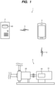
- FIG. 1 is an overall configuration diagram showing an example of a pump-operation support system 1.
- the pump-operation support system 1 functions as a system that supports a user of a pump device 2 (an owner, a manager, a working person for installation, inspection, repair, etc. of the pump device 2) in setting operating conditions of the pump device 2 when the pump device 2 is installed as a support target device.
- the control section 30 functions as a performance-characteristic acquisition section 300, an installation-state acquisition section 301, an operation-state acquisition section 302, a first operation support section 303, and a second operation support section 304, for example, by executing a pump-operation support program 320 stored in the memory section 32.
- each of the sections 300 to 304 of the control section 30 functions as an entity that performs each process (a performance-characteristic acquisition process, an installation-state acquisition process, an operation-state acquisition process, a first operation support process, and a second operation support process) in the pump-operation support method.
- the communication section 31 is coupled to the network 5 and functions as a communication interface for transmitting and receiving various data to and from, for example, the pump device 2 or the pump database device 4.
- the memory section 32 stores various programs (such as an operating system and the pump-operation support program 320) and data (such as operation-support acquisition data 321 and operation-support internal data 322) used in the operation of the pump-operation support apparatus 3.
- the input section 33 accepts various input operations, and the output section 34 functions as a user interface by outputting various information via display screen or voice.
- FIG. 3 is a data configuration diagram showing an example of the operation-support acquisition data 321 and the pump database 40.
- FIG. 4 is a data configuration diagram showing an example of the operation-support internal data 322.
- Data indicating the performance characteristics of each pump device 2 (in the example of FIG. 3 , flow-rate vs. total-pump-head typical performance curve (QH typical (Q)), flow-rate vs. power-consumption typical performance curve (QW typical (Q)), rated rotational speed (N rated ), and the number of motor poles (PoleCount)) is registered in the pump database 40 for each model number of the pump device 2.
- the pump database 40 is appropriately updated by adding, modifying, or deleting the model number and the performance characteristics based on information provided by a manufacturer of the pump device 2, for example.
- the operation-support acquisition data 321 contains data of performance characteristic acquired by the performance-characteristic acquisition section 300, data of installation state acquired by the installation-state acquisition section 301, and data of operation state acquired by the operation-state acquisition section 302 when the pump-operation support apparatus 3 is operating.
- the operation-support internal data 322 contains data of processing result (intermediate calculation result, final calculation result, etc.) of the operation support process performed by the first operation support section 303 and the second operation support section 304 when the pump-operation support apparatus 3 is operating. The processes of acquiring and calculating the various data stored in the operation-support acquisition data 321 and the operation-support internal data 322 will be described later.
- the performance-characteristic acquisition section 300 may transmit a data-transmission request including the model number (Mn) to the pump database device 4 and may acquire the performance characteristics of the support target device from the pump database device 4 in response to the data-transmission request. Furthermore, when the pump database 40 is stored in the memory section 32, the performance-characteristic acquisition section 300 may acquire the performance characteristics of the support target device by referring to the pump database 40 based on the model number.
- the performance-characteristic acquisition section 300 may transmit a data-transmission request for the performance characteristics to the pump device 2 as the support target device, and may acquire the performance characteristics of the support target device from the pump device 2 in response to the data-transmission request. In that case, the user input of the model number may be omitted.
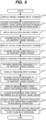
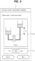
- the installation-state acquisition section 301 may acquire at least actual pump head (H static ) as the installation state in which the support target device is installed, and may further acquire installation use (Use). For example, the installation-state acquisition section 301 generates installation-state input screen information into which the installation state of the pump device 2 as the support target device can be input, and acquires the installation state of the support target device by accepting user input via an installation-state input screen (see FIG. 8 and FIG. 9 described later) based on the installation-state input screen information.
- H static actual pump head
- Use installation use
- the installation-state acquisition section 301 may transmit a data-transmission request for the installation state to the pump device 2 as the support target device, and may acquire the installation state of the support target device from the pump device 2 in response to the data-transmission request. Furthermore, when the data of the installation state of the support target device is stored in the memory section 32 or an external storage device or storage medium, the installation-state acquisition section 301 may acquire the installation state of the support target device by referring to the data.
- the operation-state acquisition section 302 may acquire at least operating frequency (F out ), suction pressure (P suction ), and discharge pressure (P discharge ) as the operation state of the support target device when the support target device is operated in the installation state, and may further acquire a measurement-point-height difference (H diff ).
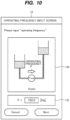
- the operation-state acquisition section 302 generates operation-state input screen information into which the operation state of the pump device 2 as the support target device can be input, and acquires the operation state of the support target device by accepting user input via an operation-state input screen (see FIGS. 10 to 12 described later) based on the operation-state input screen information.
- the operation-state acquisition section 302 may transmit a data-transmission request for the operation state to the pump device 2 as the support target device, and may acquire the operation state of the support target device from the pump device 2 in response to the data-transmission request.
- the operation-state acquisition section 302 may acquire the operation state of the support target device by referring to that data.
- the first operation support section 303 performs a first operation support process to calculate the operating conditions in the reference operation of the support target device when the support target device is operated in the installation state and the operation state. At that time, the first operation support section 303 calculates the operating conditions in the reference operation based on the performance characteristics, the installation state, and the operation state, and stores the calculation results of various data as the operation-support internal data 322.
- the operating conditions in the reference operation include, for example, flow rate (Q now ), total pump head (H now ), and energy-saving rate (ESR now ) in the reference operation.
- the time of the reference operation corresponds to a time when the support target device is operated in the installation state and the operation state, but may be a current time or a past time. In addition, the time of the reference operation may be, for example, a situation when a test operation is performed during installation, inspection, repair, etc. of the pump device 2, or a situation when normal operation is performed.
- the first operation support section 303 further functions as a user interface for the first operation support process. For example, the first operation support section 303 generates first operation support screen information that displays calculation results of operating conditions in a reference flow-rate operation calculated by the first operation support process, and displays a first operation support screen (see FIG. 18 described later) based on the first operation support screen information.
- the second operation support section 304 When the second operation support section 304 receives an input of a set flow rate (Q set ) as a flow rate at which the support target device is operated in the installation state, the second operation support section 304 performs a second operation support process to calculate operating conditions for the set flow-rate operation of the support target device when the support target device is operated in the installation state and at the set flow rate, and stores the calculation results of various data as the operation-support internal data 322.
- the operating conditions for the set flow-rate operation include, for example, command frequency (F cmdset ) in the set flow-rate operation, total pump head (H set ) and energy-saving rate (ESR set ) for the set flow-rate operation.
- the second operation support section 304 further functions as a user interface for the second operation support process.
- the second operation support section 304 generates second operation support screen information including a set flow-rate input section capable of inputting a set flow rate (Q set ), a second calculation-result display section that displays a calculation result of operating conditions in set flow-rate operation calculated by the second operation support process based on the set flow rate (Q set ) input by the set flow-rate input section, and a command-frequency setting instruction section capable of inputting a setting instruction to set the command frequency (F cmdset ) in the set flow-rate operation to the support target device.
- the command frequency (F cmdset ) serves as the operating conditions in the set flow-rate operation calculated by the second operation support process.
- the second operation support section 304 displays a second operation support screen (see FIG. 21 and FIG. 23 described later) based on the second operation support screen information.
- FIG. 5 is a hardware configuration diagram showing an example of a computer 900 constituting each device.
- Each of the pump device 2, the pump-operation support apparatus 3, and the pump database device 4 is configured by a general-purpose or dedicated computer 900.
- main components of the computer 900 include buses 910, a processor 912, a memory 914, an input device 916, an output device 917, a display device 918, a storage device 920, a communication I/F (interface) section 922, an external device I/F section 924, an I/O (input/output) device I/F section 926, and a media input/output section 928.
- the above components may be omitted as appropriate depending on an application in which the computer 900 is used.
- the processor 912 includes one or more arithmetic processing unit(s) (CPU (Central Processing Unit), MPU (Micro-processing unit), DSP (digital signal processor), GPU (Graphics Processing Unit), etc.), and operates as a controller configured to control the entire computer 900.
- the memory 914 stores various data and programs 930, and includes, for example, a volatile memory (DRAM, SRAM, etc.) that functions as a main memory, a non-volatile memory (ROM), a flash memory, etc.
- the input device 916 includes, for example, a keyboard, a mouse, a numeric keypad, an electronic pen, etc., and functions as an input section.
- the output device 917 includes, for example, a sound (voice) output device, a vibration device, etc., and functions as an output section.
- the display device 918 includes, for example, a liquid crystal display, an organic EL display, electronic paper, a projector, etc., and functions as an output section.
- the input device 916 and the display device 918 may be configured integrally, such as a touch panel display.
- the storage device 920 includes, for example, HDD (Hard Disk Drive), SSD, etc., and functions as a storage section. The storage device 920 stores various data necessary for executing the operating system and the programs 930.
- the communication I/F section 922 is coupled to a network 940, such as the Internet or an intranet (which may be the same as the network 5 in FIG. 1 ), in a wired manner or a wireless manner, and transmits and receives data to and from another computer according to a predetermined communication standard.
- the communication I/F section 922 functions as a communication unit that sends and receives information.
- the external device I/F section 924 is coupled to an external device 950, such as camera, printer, scanner, reader/writer, etc. in a wired manner or a wireless manner, and serves as a communication section that transmits and receives data to and from the external device 950 according to a predetermined communication standard.
- the I/O device I/F unit 926 is coupled to I/O devices 960, such as various sensors or actuators, and functions as a communication unit that transmits and receives various signals, such as detection signals from the sensors or control signals to the actuators, and data to and from the I/O devices 960.
- the media input/output unit 928 is constituted of a drive device, such as a DVD (Digital Versatile Disc) drive or a CD (Compact Disc) drive, a memory card slot, or a USB connector, and writes and reads data into and from medium (non-transitory storage medium) 970, such as a DVD, a CD, a memory card, or a USB memory.
- the processor 912 calls the program 930 stored in the storage device 920 into the memory 914 and executes the program 930, and controls each part of the computer 900 via the buses 910.
- the program 930 may be stored in the memory 914 instead of the storage device 920.
- the program 930 may be stored in the medium 970 in an installable file format or an executable file format, and may be provided to the computer 900 via the media input/output unit 928.
- the program 930 may be provided to the computer 900 by being downloaded via the network 940 and the communication I/F unit 922.
- the computer 900 performs various functions realized by the processor 912 executing the programs 930.
- the computer 900 may include hardware, such an FPGA (field-programmable gate array), an ASIC (application specific integrated circuit), etc. for executing the above-described various functions.
- the computer 900 is, for example, a stationary computer or a portable computer, and is an electronic device in arbitrary form.
- the computer 900 may be a client computer, a server computer, or a cloud computer.
- the operation-state acquisition section 302 acquires the operating frequency (F out ) of the support target device (in this example, "150.0") as a response to the data-transmission request.
- the operation-state acquisition section 302 then inputs the result of acquiring the operating frequency (F out ) as a default value of the operating-frequency input section 131, and displays the default value on the operating-frequency input screen 13.
- the operating-frequency input section 131 may be capable of accepting input (change) of the numerical value.
- step S121 the operation-state acquisition section 302 then acquires the operating frequency (F out ) of the support target device by accepting the user input of the operating frequency (F out ) (in this example, "150.0" received from the support target device) on the operating-frequency input screen 13.
- the operating frequency (F out ) in this example, "150.0" received from the support target device
- step S122 the operation-state acquisition section 302 generates pressure input screen information, and displays a pressure input screen 14 on the output section 34 based on the pressure input screen information.
- the values that have been input in the pressure input section 141 are results of visually reading a pressure value indicated by a suction-side pressure meter and a pressure value indicated by a discharge-side pressure meter by the user when the pump device 2 is actually operating during a test operation.
- step S123 the operation-state acquisition section 302 then acquires the suction pressure (P suction ) and the discharge pressure (P discharge ) of the support target device by accepting the user inputs of the suction pressure (P suction ) and the discharge pressure (P discharge ) on the pressure input screen 14.
- step S124 the operation-state acquisition section 302 generates measurement-point-height-difference input screen information, and displays a measurement-point-height-difference input screen 15 on the output section 34 based on the measurement-point-height-difference input screen information.
- FIG. 12 is a diagram showing an example of the measurement-point-height-difference input screen 15.
- the measurement-point-height-difference input screen 15 has, for example, an installation-use display section 150 that displays the installation use (Use) of the pump device 2 (in this example, "push"), and a measurement-point-height-difference input section 151 that is capable of accepting an input of a measurement-point-height difference (H diff ) by the user.
- FIG. 12 shows a case where "0.86" is input as the measurement-point-height difference (H diff ).
- the operation-state acquisition section 302 acquires the measurement-point-height difference (H diff ) of the support target device by accepting the user input of the measurement-point-height difference (H diff ) on the measurement-point-height-difference input screen 15.
- step S200 the first operation support section 303 calculate operating conditions in a reference operation by performing a first operation support process shown in FIGS. 13 and 14 described later, based on the performance characteristics acquired in the steps S100 to S101, the installation state acquired in the steps S110 to S113, and the operation state acquired in the steps S120 to S125. Details of the first operation support process will be described below.
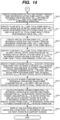
- FIGS. 13 and 14 are flowcharts showing an example of the first operation support process (step S200) performed by the first operation support section 303.
- the first operation support section 303 calculates a rated operating frequency (F rated ) corresponding to the rated rotational speed (N rated ) based on the rated rotational speed (N rated ) and the number of motor poles (PoleCount) using the following formula (2).
- F rated N rated ⁇ PoleCount / 120
- step S211 an operating rotational speed (N now ) corresponding to the operating frequency (F out ) in the reference operation is calculated based on the operating frequency (F out ) in the reference operation and the number of motor poles (PoleCount) by the following formula (3).
- N now 120 ⁇ F out / PoleCount
- a rotational-speed ratio (N ratio ) in the reference operation is calculated based on the operating rotational speed (N now ) in the reference operation and the rated rotational speed (N rated ) by the following formula (4).
- N ratio N now / N rated
- step S220 total pump head (H now ) in the reference operation is calculated based on the suction pressure (P suction ), the discharge pressure (P discharge ), and the measurement-point-height difference (H diff ) by the following formula (5).
- H now k ⁇ P suction ⁇ P discharge + H diff
- k is a coefficient ( ⁇ 102) for converting a unit of pressure [MPa] to a unit of pump head "m”.
- step S230 the flow-rate vs. total-pump-head performance curve (QH now (Q)) in the reference operation is calculated from the flow-rate vs. total-pump-head typical performance curve (QH typical (Q)) based on the rotational-speed ratio (N ratio ) between the operating rotational speed (N now ) in the reference operation and the rated rotational speed (N rated ).
- N ratio rotational-speed ratio
- the flow-rate vs. total-pump-head performance curve (QH now (Q)) in the reference operation is calculated by converting the flow-rate vs.
- FIG. 15 is a graph showing the flow-rate vs. total-pump-head performance curve (QH now (Q)) in the reference operation, and an example of calculation of the total pump head (H now ) in the reference operation and the flow rate (Q now ) in the reference operation.
- the flow-rate vs. total-pump-head performance curve (QH now (Q)) in the reference operation is calculated in the step S230 from the flow-rate vs. total-pump-head typical performance curve (QH typical (Q)).
- the flow rate (Q now ) in the reference operation is identified, in the step S231, by substituting the total pump head (H now ) in the reference operation calculated in the step S220 into the flow-rate vs. total-pump-head performance curve (QH now (Q)) in the reference operation.
- step S243 flow rate (Q rated0 ) and total pump head (H rated0 ) in a first virtual rated operation corresponding to the rated operation in a virtual state in which actual pump head in the reference operation is 0 are identified as a first virtual rated operating point (OP rated0 ) based on an intersection of the virtual system curve (CV vsys (Q)) in the reference operation and the flow-rate vs. total-pump-head typical performance curve (QH typical (Q)).
- OP rated0 first virtual rated operating point
- FIG. 17 is a graph showing a relationship between flow rate and total pump head in the reference operation, and a relationship between flow rate and power consumption.
- the virtual system curve (CV vsys (Q)) in the reference operation is created in the step S242 as a quadratic curve that passes through the point (OP 0 ) and the reference operating point (OP now ).
- the first virtual rated operating point (OP rated0 ) is identified in the step S243 as the intersection of the virtual system curve (CV vsys (Q)) in the reference operation and the flow-rate vs. total-pump-head typical performance curve (QH typical (Q)).
- the power consumption (W rated ) in the rated operation and the power consumption (W rated0 ) in the first virtual rated operation are identified in the step S244 by substituting each of the flow rate (Q rated ) in the rated operation and the flow rate (Q rated0 ) in the first virtual rated operation into the flow-rate vs. power-consumption typical performance curve (QW typical (Q)).
- the power consumption (W now ) in the reference operation is calculated in the step S245 by multiplying the power consumption (W rated0 ) in the first virtual rated operation by the cube of the rotational-speed ratio (N ratio ). It is noted that a flow-rate vs. power-consumption performance curve (QW now (Q)) in the reference operation shown by a dashed line in FIG. 17 is not calculated as a quadratic curve, but is shown for reference.
- step S250 the first operation support section 303 then generates first operation support screen information that displays calculation results of the operating conditions in the reference operation as results of performing the first operation support process as described above, and displays a first operation support screen 16 on the output section 34 based on the first operation support screen information.
- FIG. 18 is a diagram showing an example of the first operation support screen 16.
- the first operation support screen 16 has, for example, an input-content display section 160 that displays the input contents input on the screens 10 to 15, a first calculation-result display section 161 that displays the calculation result of the operating conditions in the reference operation calculated by the first operation support process, and a flow-rate setting button 162 capable of inputting a display instruction of the second operation support screen 17 (see FIG. 21 and FIG. 23 described later) for setting flow rate of the support target device.
- the first calculation-result display section 161 displays, for example, the flow rate (Q now ), the total pump head (H now ), the energy-saving rate (ESR now ), and the operating rotational speed (N now ) as the operating conditions in the reference operation.
- the first calculation-result display section 161 may display other data as long as the data has been stored in the operation-support internal data 322 in the first operation support process.
- the second operation support section 304 displays the second operation support screen 17 (see FIGS. 21 and 23 described later) in response to pressing of the flow-rate setting button 162 on the first operation support screen 16.
- the second operation support section 304 receives an input of a set flow rate (Q set ) on the second operation support screen 17 as a flow rate at which the support target device is operated in the installation state, and calculates operating conditions in the set flow-rate operation by performing steps shown in FIGS. 19 and 20 described later as the second operation support process. Details of the second operation support process will be described below.
- FIGS. 19 and 20 are flowcharts showing an example of the second operation support process (step S300) performed by the second operation support section 304.
- step S310 the second operation support section 304 generates second operation support screen information in response to pressing of the flow-rate setting button 162 on the first operation support screen 16, and displays the second operation support screen 17 on the output section 34 based on the second operation support screen information.
- FIG. 21 is a diagram showing an example of the second operation support screen 17.
- the second operation support screen 17 has a set flow-rate input section 170 capable of inputting a set flow rate (Q set ) that can be changed stepwise or continuously, an operating-condition calculating button 171 capable of inputting a performing instruction to perform the second operation support process that calculates operating conditions in the set flow-rate operation based on the set flow rate (Q set ) input by the set flow-rate input section 170, a second calculation-result display section 172 that displays a calculation result of the operating conditions in the set flow-rate operation calculated by the second operation support process, and a command-frequency setting button 173 capable of inputting a setting instruction to set the command frequency (F cmdset ) in the set flow-rate operation to the support target device.
- the command frequency (F cmdset ) serves as the operating conditions in the set flow-rate operation calculated by the second operation support process.
- the set flow-rate input section 170 is configured to input the set flow rate (Q set ) by sliding a pointer 170b along an arc 170a.
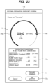
- FIG. 23 shows a case where the set flow rate (Q set ) is changed from "1.010" of the flow rate (Q now ) in the reference operation to "0.940" of an input flow rate as shown in a flow rate 170c.
- the second calculation-result display section 172 does not display the calculation result, and the command-frequency setting button 173 is displayed in a manner such that the command-frequency setting button 173 cannot be pressed (grayed out).
- the operating-condition calculating button 171 may be omitted.
- the second operation support section 304 may calculate the operating conditions in the set flow-rate operation in response to input of the set flow rate (Q set ) on the set flow-rate input section 170.
- step S311 the second operation support section 304 then receives the user input of the set flow rate (Q set ) (in this example, "0.940") set in the set flow-rate input section 170 in response to pressing of the operating-condition calculating button 171 on the second operation support screen 17.
- Q set the set flow rate (in this example, "0.940") set in the set flow-rate input section 170 in response to pressing of the operating-condition calculating button 171 on the second operation support screen 17.
- step S320 the command frequency (F cmdset ) in the set flow-rate operation is calculated based on a ratio of the set flow rate (Q set ) to the flow rate (Q rated ) in the rated operation and the rated operating frequency (F rated ) corresponding to the rated rotational speed (N rated ) by the following formula (12).
- the second operation support section 304 may calculate the rated operating frequency (F rated ), create the system curve (CV sys (Q)), and specify the flow rate (Q rated ) in the rated operation in the same manner as the first operation support section 303, or may refer to the operation-support internal data 322 stored as the calculation results calculated by the first operation support section 303.
- F cmdset Q set / Q rated ⁇ F rated
- step S321 an operating rotational speed (N set ) corresponding to the command frequency (F cmdset ) in the set flow-rate operation is calculated based on the command frequency (F cmdset ) in the set flow-rate operation and the number of motor poles (PoleCount) by the following equation (13).
- N set 120 ⁇ F out / PoleCount
- step S323 a total pump head (H set ) in the set flow-rate operation is identified from a point that satisfies the set flow rate (Q set ) on the system curve (CV sys (Q)).
- step S330 a virtual system curve (CV vsysset (Q)) in the set flow-rate operation is created that passes through a point (OP 0 ) specified by the flow rate of 0 and the total pump head of 0 and a set flow-rate operating point (OP set ) specified by the set flow rate (Q set ) and the total pump head (H set ) in the set flow-rate operation in a relationship between flow rate and total pump head (see FIG. 22 described later).
- CV vsysset (Q) virtual system curve in the set flow-rate operation is created that passes through a point (OP 0 ) specified by the flow rate of 0 and the total pump head of 0 and a set flow-rate operating point (OP set ) specified by the set flow rate (Q set ) and the total pump head (H set ) in the set flow-rate operation in a relationship between flow rate and total pump head (see FIG. 22 described later).
- step S332 power consumption (W rated ) in the rated operation is identified from a point that satisfies the flow rate (Q rated ) in the rated operation on the flow-rate vs. power-consumption typical performance curve (QW typical (Q)), and power consumption (W rated0set ) in the second virtual rated operation is identified from a point that satisfies the flow rate (Q rated0set ) in the second virtual rated operation.
- QW typical (Q) power-consumption typical performance curve
- step S333 power consumption (W set ) in the set flow-rate operation is calculated from the power consumption (W rated0set ) in the second virtual rated operation based on the rotational-speed ratio (N ratioset ) between the operating rotational speed (N set ) in the set flow-rate operation and the rated rotational speed (N rated ) by the following formula (15).
- W set W rated 0 set ⁇ N ratioset 3
- step S334 energy-saving power (ESW set ) in the set flow-rate operation is calculated by subtracting the power consumption (W set ) in the set flow-rate operation from the power consumption (W rated ) in the rated operation by the following formula (16).
- Energy-saving rate (ESR set ) in the set flow-rate operation is calculated based on a ratio of the energy-saving power (ESW set ) in the set flow-rate operation to the power consumption (W rated ) in the rated operation by the following formula (17).
- ESW set W rated ⁇ W set
- ESR set ESW set / W rated ⁇ 100
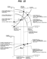
- FIG. 22 is a graph showing a relationship between flow rate and total pump head in the set flow-rate operation, and a relationship between flow rate and power consumption.
- the virtual system curve (CV vsysset (Q)) in the set flow-rate operation is created in the step S330 as a quadratic curve that passes through the point (OP 0 ) and the set flow-rate operating point (OP set ).
- the second virtual rated operating point (OP rated0set ) is identified in the step S331 as the intersection of the virtual system curve (CV vsysset (Q)) in the set flow-rate operation and the flow-rate vs. total-pump-head typical performance curve (QH typical (Q)).
- the power consumption (W rated ) in the rated operation and the power consumption (W rated0set ) in the second virtual rated operation are identified in the step S332 by substituting each of the flow rate (Q rated ) in the rated operation and the flow rate (Q rated0set ) in the second virtual rated operation into the flow-rate vs. power-consumption typical performance curve (QW typical (Q)).
- the power consumption (W set ) in the set flow-rate operation is calculated in the step S333 by multiplying the power consumption (W rated0set ) in the second virtual rated operation by the cube of the rotational-speed ratio (N ratioset ). It is noted that a flow-rate vs. power-consumption performance curve (QW set (Q)) in the set flow-rate operation shown by a dashed line in FIG. 22 is not calculated as a quadratic curve, but is shown for reference.
- step S340 the second operation support section 304 then generates second operation support screen information that displays calculation results of the operating conditions in the set flow-rate operation as results of performing the second operation support process as described above, and updates the second operation support screen 17 based on the second operation support screen information.
- FIG. 23 is a diagram showing an example of a second operation support screen 17a after updated.
- the updated second operation support screen 17a has the same configuration as that of the second operation support screen 17 shown in FIG. 21 .
- a second calculation-result display section 172a displays, for example, the command frequency (F cmdset ), the total pump head (H set ), the energy-saving rate (ESR set ), and the operating rotational speed (N set ) as the operating conditions in the set flow-rate operation.
- the second calculation-result display section 172a may display other data as long as the data has been stored in the operation-support internal data 322 in the second operation support process.
- the screens 10 to 17 are displayed when the pump-operation support apparatus 3 performs the pump-operation support method, while the display contents, the display form, the display layout, the input method, etc. of the screens 10 to 17 may be appropriately changed.
- each of the screens 10 to 17 may be displayed as a plurality of screens, and for example, the second operation support screens 17 and 17a may be displayed as separate screens, with the second operation support screen 17 having the set flow rate input section 170 and the operating-condition calculating button 171, and the second operation support screen 17a having the second calculation-result display section 172 and the command-frequency setting button 173.
- the present invention is applicable to a pump-operation support method and a pump-operation support apparatus.
Landscapes
- Engineering & Computer Science (AREA)
- Mechanical Engineering (AREA)
- General Engineering & Computer Science (AREA)
- Computer Hardware Design (AREA)
- Control Of Non-Positive-Displacement Pumps (AREA)
- Control Of Positive-Displacement Pumps (AREA)
Applications Claiming Priority (2)
| Application Number | Priority Date | Filing Date | Title |
|---|---|---|---|
| JP2022095238A JP7723642B2 (ja) | 2022-06-13 | 2022-06-13 | ポンプ運転支援方法、及び、ポンプ運転支援装置 |
| PCT/JP2023/014340 WO2023243193A1 (ja) | 2022-06-13 | 2023-04-07 | ポンプ運転支援方法、及び、ポンプ運転支援装置 |
Publications (1)
| Publication Number | Publication Date |
|---|---|
| EP4538531A1 true EP4538531A1 (de) | 2025-04-16 |
Family
ID=89190895
Family Applications (1)
| Application Number | Title | Priority Date | Filing Date |
|---|---|---|---|
| EP23823497.5A Pending EP4538531A1 (de) | 2022-06-13 | 2023-04-07 | Verfahren zur unterstützung des betriebs einer pumpe und vorrichtung zur unterstützung des betriebs einer pumpe |
Country Status (5)
| Country | Link |
|---|---|
| EP (1) | EP4538531A1 (de) |
| JP (1) | JP7723642B2 (de) |
| CN (1) | CN119384557A (de) |
| TW (1) | TW202348899A (de) |
| WO (1) | WO2023243193A1 (de) |
Families Citing this family (1)
| Publication number | Priority date | Publication date | Assignee | Title |
|---|---|---|---|---|
| CN118960914B (zh) * | 2024-10-16 | 2025-01-21 | 新界泵业(浙江)有限公司 | 一种电子泵流量反馈校准方法及系统 |
Family Cites Families (4)
| Publication number | Priority date | Publication date | Assignee | Title |
|---|---|---|---|---|
| JP3392605B2 (ja) | 1995-10-24 | 2003-03-31 | 三菱重工業株式会社 | 大容量ポンプの流量計測装置 |
| AU3053799A (en) | 1998-04-03 | 1999-10-25 | Ebara Corporation | Diagnosing system for fluid machinery |
| JP5081514B2 (ja) * | 2007-07-04 | 2012-11-28 | 株式会社日立製作所 | 省エネルギー運転支援方法における省消費電力効果の算出方法、省エネルギー運転支援システム、および省消費電力効果の算出プログラム |
| JP5215647B2 (ja) | 2007-11-29 | 2013-06-19 | アズビル株式会社 | ポンプ吐出抵抗検査装置および方法 |
-
2022
- 2022-06-13 JP JP2022095238A patent/JP7723642B2/ja active Active
-
2023
- 2023-04-07 CN CN202380046143.3A patent/CN119384557A/zh active Pending
- 2023-04-07 WO PCT/JP2023/014340 patent/WO2023243193A1/ja not_active Ceased
- 2023-04-07 EP EP23823497.5A patent/EP4538531A1/de active Pending
- 2023-06-06 TW TW112120952A patent/TW202348899A/zh unknown
Also Published As
| Publication number | Publication date |
|---|---|
| CN119384557A (zh) | 2025-01-28 |
| WO2023243193A1 (ja) | 2023-12-21 |
| JP2023181866A (ja) | 2023-12-25 |
| JP7723642B2 (ja) | 2025-08-14 |
| TW202348899A (zh) | 2023-12-16 |
Similar Documents
| Publication | Publication Date | Title |
|---|---|---|
| EP1686461B1 (de) | Verfahren und System zur Simulation einer Zielgerätanzeige | |
| US8789024B2 (en) | Integration of visualization with source code in the Eclipse development environment | |
| RU2439688C2 (ru) | Идентификация проектных проблем в электронных формах | |
| CN108228287B (zh) | 基于qt的用户界面控件的生成方法及装置 | |
| US20120062577A1 (en) | Methods and apparatus to display process control information | |
| US20040196286A1 (en) | Progressive scale graph | |
| US20030056181A1 (en) | System and method for displaying spreadsheet cell formulas in two dimensional mathematical notation | |
| CN103558966B (zh) | 用于缩放可视化图像的系统 | |
| JP5289949B2 (ja) | 航空機フラットパネル表示システム | |
| EP4538531A1 (de) | Verfahren zur unterstützung des betriebs einer pumpe und vorrichtung zur unterstützung des betriebs einer pumpe | |
| JPWO2015170408A1 (ja) | 監視制御システム、監視端末及び監視プログラム | |
| CN117744387B (zh) | 基于数字孪生的医院临床保障和机电设备智能诊断方法 | |
| US11113610B2 (en) | System for building and deploying inference model | |
| US20240176932A1 (en) | Continuous online validation of process measurements in digital twins | |
| JP5156775B2 (ja) | プラント監視・制御装置およびその保守支援方法 | |
| US7624350B2 (en) | System and method for XML based data driven generation of a composite source user interface | |
| JP2024044714A (ja) | データ処理装置、物理量計測装置、データ処理システム、及び、データ処理方法 | |
| JP7805496B1 (ja) | 表示制御方法、表示制御装置、及び表示制御プログラム | |
| JP2024041477A (ja) | データ処理装置、物理量計測装置、データ処理システム、及び、データ処理方法 | |
| EP4703827A1 (de) | Berichterzeugungssystem, berichterzeugungsverfahren und programm | |
| JP2019220105A (ja) | データ抽出方法およびデータ抽出装置 | |
| WO2025258455A1 (ja) | 作業支援システム、及び、作業支援方法 | |
| Kramer et al. | Onsite Analysis of Sucker Rod Pumping Wells | |
| WO2024075444A1 (ja) | データ処理システム、データ収集装置、物理量計測装置、データ処理方法、データ収集方法、データ提供方法、及び、データ構造 | |
| JP2007241534A (ja) | システム性能情報出力装置およびコンピュータプログラム |
Legal Events
| Date | Code | Title | Description |
|---|---|---|---|
| STAA | Information on the status of an ep patent application or granted ep patent |
Free format text: STATUS: THE INTERNATIONAL PUBLICATION HAS BEEN MADE |
|
| PUAI | Public reference made under article 153(3) epc to a published international application that has entered the european phase |
Free format text: ORIGINAL CODE: 0009012 |
|
| STAA | Information on the status of an ep patent application or granted ep patent |
Free format text: STATUS: REQUEST FOR EXAMINATION WAS MADE |
|
| 17P | Request for examination filed |
Effective date: 20241216 |
|
| AK | Designated contracting states |
Kind code of ref document: A1 Designated state(s): AL AT BE BG CH CY CZ DE DK EE ES FI FR GB GR HR HU IE IS IT LI LT LU LV MC ME MK MT NL NO PL PT RO RS SE SI SK SM TR |
|
| DAV | Request for validation of the european patent (deleted) | ||
| DAX | Request for extension of the european patent (deleted) |