EP4538240A1 - Device and method for producing glass article and method for measuring liquid-surface height - Google Patents
Device and method for producing glass article and method for measuring liquid-surface height Download PDFInfo
- Publication number
- EP4538240A1 EP4538240A1 EP23849876.0A EP23849876A EP4538240A1 EP 4538240 A1 EP4538240 A1 EP 4538240A1 EP 23849876 A EP23849876 A EP 23849876A EP 4538240 A1 EP4538240 A1 EP 4538240A1
- Authority
- EP
- European Patent Office
- Prior art keywords
- pipe
- nozzle
- molten glass
- liquid
- storage tank
- Prior art date
- Legal status (The legal status is an assumption and is not a legal conclusion. Google has not performed a legal analysis and makes no representation as to the accuracy of the status listed.)
- Pending
Links
Images



Classifications
-
- C—CHEMISTRY; METALLURGY
- C03—GLASS; MINERAL OR SLAG WOOL
- C03B—MANUFACTURE, SHAPING, OR SUPPLEMENTARY PROCESSES
- C03B5/00—Melting in furnaces; Furnaces so far as specially adapted for glass manufacture
- C03B5/16—Special features of the melting process; Auxiliary means specially adapted for glass-melting furnaces
-
- C—CHEMISTRY; METALLURGY
- C03—GLASS; MINERAL OR SLAG WOOL
- C03B—MANUFACTURE, SHAPING, OR SUPPLEMENTARY PROCESSES
- C03B5/00—Melting in furnaces; Furnaces so far as specially adapted for glass manufacture
- C03B5/16—Special features of the melting process; Auxiliary means specially adapted for glass-melting furnaces
- C03B5/24—Automatically regulating the melting process
- C03B5/245—Regulating the melt or batch level, depth or thickness
-
- C—CHEMISTRY; METALLURGY
- C03—GLASS; MINERAL OR SLAG WOOL
- C03B—MANUFACTURE, SHAPING, OR SUPPLEMENTARY PROCESSES
- C03B5/00—Melting in furnaces; Furnaces so far as specially adapted for glass manufacture
- C03B5/04—Melting in furnaces; Furnaces so far as specially adapted for glass manufacture in tank furnaces
-
- C—CHEMISTRY; METALLURGY
- C03—GLASS; MINERAL OR SLAG WOOL
- C03B—MANUFACTURE, SHAPING, OR SUPPLEMENTARY PROCESSES
- C03B5/00—Melting in furnaces; Furnaces so far as specially adapted for glass manufacture
- C03B5/16—Special features of the melting process; Auxiliary means specially adapted for glass-melting furnaces
- C03B5/167—Means for preventing damage to equipment, e.g. by molten glass, hot gases, batches
- C03B5/1672—Use of materials therefor
- C03B5/1675—Platinum group metals
-
- G—PHYSICS
- G01—MEASURING; TESTING
- G01F—MEASURING VOLUME, VOLUME FLOW, MASS FLOW OR LIQUID LEVEL; METERING BY VOLUME
- G01F23/00—Indicating or measuring liquid level or level of fluent solid material, e.g. indicating in terms of volume or indicating by means of an alarm
- G01F23/14—Indicating or measuring liquid level or level of fluent solid material, e.g. indicating in terms of volume or indicating by means of an alarm by measurement of pressure
- G01F23/16—Indicating, recording, or alarm devices being actuated by mechanical or fluid means, e.g. using gas, mercury, or a diaphragm as transmitting element, or by a column of liquid
- G01F23/165—Indicating, recording, or alarm devices being actuated by mechanical or fluid means, e.g. using gas, mercury, or a diaphragm as transmitting element, or by a column of liquid of bubbler type
- G01F23/168—Indicating, recording, or alarm devices being actuated by mechanical or fluid means, e.g. using gas, mercury, or a diaphragm as transmitting element, or by a column of liquid of bubbler type with electric indicating or recording
Definitions
- the present invention relates to a technology to measure a liquid-surface height of a molten glass stored in a storage tank.
- a storage tank in which a molten glass is stored is used. It is required for this kind of storage tank that a large change in liquid-surface height of the molten glass stored in the storage tank be suppressed so as to achieve homogenization of the molten glass or stabilize a flow rate of the molten glass. Thus, it is important to measure the liquid-surface height of the molten glass.
- Patent Literature 1 JP 2021-151948 A
- the flow passage member is liable to be damaged or wear out due to heat or be eroded by the molten glass, and thus, in some cases, is required to be replaced.
- the flow passage member is introduced into the molten glass at a position lower than a liquid surface of the molten glass through a bottom wall or a side wall of the storage tank (melting furnace). That is, an introduction portion (hole) for the flow passage member in a wall portion of the storage tank is located at a position lower than the liquid surface of the molten glass and is facing the molten glass.
- the pipe can be made shorter than in a case in which a pipe is provided to pass through a ceiling wall of the storage tank.
- facility costs can be reduced.
- a holding member for the nozzle is not required to be additionally provided.
- a facility configuration can be simplified, and the facility costs can be reduced.
- the nozzle comprise: a fire-resistant layer being made of a refractory and covering the pipe portion; and a protective layer being made of platinum or a platinum alloy and covering the fire-resistant layer.
- the melting furnace 1 is a space for performing a melting step of obtaining a molten glass Gm.
- the melting furnace 1 functions as a storage tank for storing the molten glass Gm.
- the transfer pipes 6 to 9 are each formed of, for example, a tubular pipe made of platinum or a platinum alloy, and are each configured to transfer the molten glass Gm in a lateral direction (substantially horizontal direction).
- the transfer pipes 6 to 9 are heated through application of a current as required.
- the platinum comprises strengthened platinum, and the platinum alloy comprises a strengthened platinum alloy (the same applies hereinafter).
- the melting furnace 1 comprises a bottom wall 1a, a side wall 1b, and a ceiling wall 1c. Those constituent elements 1a to 1c define a space for storing the molten glass Gm.
- the side wall 1b comprises a front wall 1b1, a rear wall 1b2, a left wall 1b3, and a right wall 1b4.
- a feed port 10 for feeding the glass raw materials Ga is formed in the front wall 1b1 of the melting furnace 1.
- a screw feeder 11 serving as a raw material supply part is provided in the feed port 10.
- the raw material supply part may be other publicly known part, such as a pusher or a vibrating feeder.
- the number or arrangement position of the raw material supply part may be appropriately changed depending on the size of the melting furnace 1, or the like.
- An outflow port 12 for allowing outflow of the molten glass Gm is formed in the rear wall 1b2 of the melting furnace 1.
- the transfer pipe 6 is connected to the outflow port 12 so that the molten glass Gm is supplied sequentially to a downstream side.
- a plurality of rod-shaped electrodes 13 are mounted to the bottom wall 1a of the melting furnace 1.
- the shape of the electrode 13 is not limited to a rod shape, and may be a sheet shape, a block shape, or a combination thereof.
- the mounting positions of the electrodes 13 are not limited to the bottom wall 1a, and the electrodes 13 may be mounted to the left wall 1b3 and the right wall 1b4.
- the electrode 13 is made of, for example, molybdenum (Mo).
- Mo molybdenum
- the electrodes 13 heat the molten glass Gm through application of a current in a state of being immersed in the molten glass Gm.
- the electrodes 13 pass through through holes formed in the bottom wall 1a in a state of being held in cylindrical electrode holders 14, each comprising a cooling mechanism (not shown).
- a heating method used in the melting furnace 1 is not limited to all-electric melting using only heating through application of a current, and may be, for example, a heating method using only combustion (burner) of a gas fuel, which is performed from above a liquid surface LS of the molten glass Gm, or a heating method using a combination of heating through application of a current and combustion of a gas fuel.
- the nozzle 22 generates, from its distal end, air bubbles B in the molten glass Gm.
- the nozzle 22 is immersed from above the liquid surface LS into the molten glass Gm.
- the nozzle 22 has a substantially vertical posture, and comprises a first part 22a and a second part 22b.
- the first part 22a is positioned below the liquid surface LS and is immersed in the molten glass Gm.
- the second part 22b is positioned above the liquid surface LS and is not immersed in the molten glass Gm.
- the first part 22a comprises the distal end portion of the nozzle 22, and the second part 22b comprises a proximal end portion of the nozzle 22.
- the nozzle 22 may have an inclined posture.
- the pipe 23 allows supply of a gas A for generating the air bubbles B to the nozzle 22.
- the gas A is supplied into the pipe 23 from the gas supply part (for example, compressor) 24.
- the pipe 23 is led, with a substantially horizontal posture, from an outside of the melting furnace 1 into the melting furnace 1 through a transverse hole X1 that is formed in the side wall 1b (left wall 1b3 in the illustrated example) of the melting furnace 1 at a position higher than the liquid surface LS.
- the pipe 23 led into the melting furnace 1 is bent downward so as to change its posture from the substantially horizontal posture into a substantially vertical posture in a space above the liquid surface LS, and is connected to the proximal end portion of the nozzle 22, which is positioned above the liquid surface LS. That is, the pipe 23 is not in contact with the molten glass Gm.
- the pipe 23 comprises a first straight part 23a, a second straight part 23b, and a third straight part 23c.
- the first straight part 23a extends in a substantially horizontal direction.
- the second straight part 23b extends in a substantially vertical direction.
- the third straight part 23c is provided between the first straight part 23a and the second straight part 23b, and is inclined downward from the first straight part 23a to reach the second straight part 23b.
- the first straight part 23a is arranged so as to extend between an inside and the outside of the melting furnace 1 through the transverse hole X1 in the side wall 1b.
- the second straight part 23b and the third straight part 23c are arranged in the melting furnace 1.
- the shape of the pipe 23 is not limited to any particular shape.
- the pipe 23 may be formed by, for example, coupling the first straight part 23a and the second straight part 23b to each other to define a substantially right angle without comprising the third straight part 23c or may comprise a curved part in place of the third straight part 23c.
- the transverse hole X1 through which the pipe 23 is to be inserted is positioned above the liquid surface LS of the molten glass Gm.
- leakage of the molten glass Gm from the transverse hole X1 to the outside does not substantially occur.
- the liquid-surface height measurement device 21 can easily be maintained and easily be applied to an existing melting furnace 1.
- the pressure gauge 25 is configured to measure a pressure (back pressure) in the pipe 23 or the nozzle 22 when the air bubbles B are generated in the molten glass Gm with the gas A supplied from the distal end of the nozzle 22.
- the pipe 23 and the nozzle 22 form one gas supply path.
- the pressure in the pipe 23 and the pressure in the nozzle 22 are substantially the same.
- any of the pressure in the pipe 23 and the pressure in the nozzle 22 may be measured.
- the pressure gauge 25 measures the pressure in the pipe 23 outside the melting furnace 1.
- the height H1 of the liquid surface LS of the molten glass Gm is determined in the following manner.
- the pressure gauge 25 is formed of a differential pressure gauge (for example, a gauge pressure meter).
- the pressure P2 at the liquid surface LS of the molten glass Gm inside the melting furnace 1 is sometimes adjusted to be higher than or lower than an atmospheric pressure PA. Even in those cases, however, a difference between the pressure P2 at the liquid surface LS of the molten glass Gm and the atmospheric pressure PA is slight, and thus the pressure P2 and the atmospheric pressure PA can be regarded as being substantially equal to each other.
- the pressure gauge 25 is configured to measure a differential pressure (P1-PA) between the pressure P1 in the pipe 23 and the atmospheric pressure PA in place of measuring the differential pressure (P1-P2) between the pressure P1 in the pipe 23 and the pressure P2 at the liquid surface LS of the molten glass Gm . Then, the measurement of the differential pressure (P1-PA) allows the calculation of the height H1 of the liquid surface LS of the molten glass Gm from Expression (4).
- H 1 P 1 ⁇ PA / ⁇ g
- the protective layer 29 is a layer made of platinum or a platinum alloy for covering the fire-resistant layer 28. With the protective layer being provided in this manner, the erosion of the fire-resistant layer 28 by the molten glass Gm can be suppressed.
- the distal end of the fire-resistant layer 28 and the distal end of the protective layer 29 respectively comprise flat surface portions 28a and 29a that are substantially orthogonal to a longitudinal direction of the pipe portion 27.
- an outer diameter of the distal end portion of the nozzle 22 can be reduced.
- the air bubbles B are less liable to stagnate around the distal end portion of the nozzle 22.
- the back pressure is properly exerted in the nozzle 22 or the pipe 23.
- measurement accuracy for the height H1 of the liquid surface LS is improved.
- the pipe 23 comprises an inner pipe and a cooling structure.
- the gas A for generating the air bubbles B in the molten glass Gm flows through the inner pipe.
- the cooling structure is arranged so as to cover the inner pipe.
- the inner pipe and the cooling structure can be made of, for example, stainless steel or heat-resistant steel.
- a proximal end portion of the inner pipe is in communication with the gas supply part 24.
- a distal end portion of the inner pipe is in communication with a proximal end portion of the pipe portion 27 of the nozzle 22.
- the glass raw materials Ga supplied into the melting furnace 1 are heated to produce the molten glass Gm.
- the liquid surface LS of the molten glass Gm may be covered with a covering layer Gx.
- the covering layer Gx comprises the glass raw materials Ga and/or a foam layer Gb.
- the foam layer Gb is formed along with the generation of a carbon oxide gas (CO or CO 2 ), an O 2 gas, an SO 2 gas or the like from the glass raw materials Ga. Heat dissipation from the molten glass Gm can be suppressed by covering the liquid surface LS of the molten glass Gm with the covering layer Gx as described above. As a result, a temperature of the molten glass Gm can be reliably maintained, and hence energy saving can be achieved.
- the foam layer Gb may be omitted.
- the molten glass Gm is supplied to the forming body 5.
- the forming body 5 causes the molten glass Gm to overflow from the overflow groove to flow down along the side wall surfaces of the forming body 5.
- the forming body 5 causes the molten glasses Gm having flowed down to join each other at lower end portions to thereby form the glass ribbon Gr.
- the glass ribbon Gr is cooled in an annealing furnace.
- the glass ribbon Gr is cut by a cutting device.
- a glass sheet having predetermined dimensions is cut out from the glass ribbon Gr.
- the glass ribbon Gr may be taken up into a roll to thereby obtain a glass roll (take-up step).
- a modification example of the nozzle 22 of the liquid-surface measurement device 21 is exemplified.
- a modification example of the pipe 23 of the liquid-surface measurement device 21 is exemplified.
- a length of the pipe 23 has a tendency to be longer than in a case in which the pipe 23 is led from the outside of the melting furnace 1 into the melting furnace 1 through the transverse hole X1 in the side wall 1b.
- the measurement of the height of the liquid surface of the molten glass stored in the melting furnace has been described.
- the present invention is also applicable to measurement of a height of a liquid surface of a molten glass stored in a storage tank other than the melting furnace, such as a feeder connected to the melting furnace or a fining bath having furnace walls made of a refractory.
- the feeder comprises a bushing including a plurality of nozzles for forming a glass fiber from a molten glass.
Landscapes
- Chemical & Material Sciences (AREA)
- Engineering & Computer Science (AREA)
- Materials Engineering (AREA)
- Organic Chemistry (AREA)
- Physics & Mathematics (AREA)
- Fluid Mechanics (AREA)
- General Physics & Mathematics (AREA)
- Waste-Gas Treatment And Other Accessory Devices For Furnaces (AREA)
- Measurement Of Levels Of Liquids Or Fluent Solid Materials (AREA)
Abstract
Description
- The present invention relates to a technology to measure a liquid-surface height of a molten glass stored in a storage tank.
- For a manufacturing method for a glass article such as a glass fiber or a glass sheet, a storage tank in which a molten glass is stored is used. It is required for this kind of storage tank that a large change in liquid-surface height of the molten glass stored in the storage tank be suppressed so as to achieve homogenization of the molten glass or stabilize a flow rate of the molten glass. Thus, it is important to measure the liquid-surface height of the molten glass.
- As a liquid-surface height measurement device configured to measure the liquid-surface height of the molten glass, there is disclosed in
Patent Literature 1, for example, a liquid-surface height measurement device that supplies a gas into the molten glass via a flow passage member to generate air bubbles. The liquid-surface height measurement device determines the liquid-surface height of the molten glass based on a pressure (back pressure) in the flow passage member under a state in which the air bubbles are being generated. - Patent Literature 1:
JP 2021-151948 A - In the liquid-surface height measurement device described in
Patent Literature 1, the flow passage member is liable to be damaged or wear out due to heat or be eroded by the molten glass, and thus, in some cases, is required to be replaced. However, the flow passage member is introduced into the molten glass at a position lower than a liquid surface of the molten glass through a bottom wall or a side wall of the storage tank (melting furnace). That is, an introduction portion (hole) for the flow passage member in a wall portion of the storage tank is located at a position lower than the liquid surface of the molten glass and is facing the molten glass. Thus, when the flow passage member is replaced, there arises a risk of leakage of the molten glass stored in the storage tank from the introduction portion for the flow passage member. As a result, there arises a problem in that the liquid-surface height measurement device described inPatent Literature 1 is extremely difficult to maintain. - Further, when the liquid-surface height measurement device described in
Patent Literature 1 is to be applied to an existing storage tank, an introduction portion for the flow passage member is required to be additionally formed in the wall portion of the storage tank at a position lower than the liquid surface of the molten glass. However, the molten glass is already stored in the existing storage tank. Thus, when the introduction portion for the flow passage member is formed, the molten glass may leak out. Thus, there arises another problem in that the liquid-surface height measurement device described inPatent Literature 1 is extremely difficult to apply to the existing storage tank. - The present invention has an object to provide a liquid-surface height measurement device and a liquid-surface height measurement method that allow easy maintenance and easy application to an existing storage tank.
-
- (1) According to the present invention devised in order to solve the problems described above, there is provided a manufacturing apparatus for a glass article, comprising: a storage tank configured to store a molten glass; and a liquid-surface height measurement device configured to measure a height of a liquid surface of the molten glass stored in the storage tank. The liquid-surface height measurement device comprises: a nozzle to be immersed from above the liquid surface into the molten glass; a pipe, which is led from an outside of the storage tank into the storage tank at a position higher than the liquid surface and is configured to allow supply of a gas to the nozzle; and a pressure gauge configured to measure a pressure in the pipe or the nozzle.
- In this manner, the nozzle is immersed from above the liquid surface of the molten glass into the molten glass, and the pipe is led from the outside of the storage tank into the storage tank at a position higher than the liquid surface of the molten glass. That is, an introduction portion for the pipe in a wall portion of the storage tank is located at the position higher than the liquid surface of the molten glass. Thus, leakage of the molten glass from the introduction portion for the pipe does not substantially occur. Thus, the liquid-surface height measurement device can easily be maintained and easily be applied to an existing storage tank.
- (2) In the configuration of the above-mentioned item (1), it is preferred that the pipe be led from the outside of the storage tank into the storage tank through a hole formed in a side wall of the storage tank.
- In this manner, the pipe can be made shorter than in a case in which a pipe is provided to pass through a ceiling wall of the storage tank. Thus, facility costs can be reduced.
- (3) In the configuration of the above-mentioned item (1) or (2), it is preferred that the nozzle be held at a predetermined height by the pipe.
- In this manner, a holding member for the nozzle is not required to be additionally provided. Thus, a facility configuration can be simplified, and the facility costs can be reduced.
- (4) In the configuration of any one of the above-mentioned items (1) to (3), it is preferred that the pipe comprise a cooling structure.
- In this manner, damage and wear due to heat of the pipe can be suppressed.
- (5) In the configuration of any one of the above-mentioned items (1) to (4), it is preferred that the nozzle comprise a pipe portion made of platinum or a platinum alloy, through which the gas is to flow.
- In this manner, damage and wear due to heat and erosion by the molten glass can be suppressed.
- (6) In the configuration of the above-mentioned item (5), it is preferred that the nozzle comprise: a fire-resistant layer being made of a refractory and covering the pipe portion; and a protective layer being made of platinum or a platinum alloy and covering the fire-resistant layer.
- In this manner, the erosion of the nozzle by the molten glass can be suppressed by the protective layer. Further, strength of the nozzle can be improved by the fire-resistant layer. Thus, deformation of the nozzle under a force from glass raw materials or the molten glass at the time of immersion into the molten glass can be suppressed.
- (7) In the configuration of the above-mentioned item (6), it is preferred that a distal end portion of the pipe portion be free from being covered with the fire-resistant layer, and be exposed.
- In this manner, an outer diameter of a distal end of the nozzle can be reduced. Hence, air bubbles are less liable to stagnate around the distal end of the nozzle. Thus, when the air bubbles are generated from the distal end of the nozzle, a back pressure corresponding to a pressure applied to the molten glass around the distal end of the nozzle properly acts inside the nozzle or the pipe. As a result, measurement accuracy for the height of the liquid surface is improved.
- (8) According to the present invention devised in order to solve the problems described above, there is provided a liquid-surface height measurement method of measuring a height of a liquid surface of a molten glass stored in a storage tank, the method comprising: providing: a nozzle to be immersed from above the liquid surface into the molten glass; and a pipe, which extends from an outside of the storage tank through a space above the molten glass in the storage tank, and is configured to allow supply of a gas to the nozzle; and determining the height of the liquid surface based on a pressure in the pipe or the nozzle.
- In this manner, the same actions and effects as those of the corresponding configurations that have been described above can be enjoyed.
- (9) According to the present invention devised in order to solve the problems described above, there is provided a manufacturing method for a glass article, comprising a liquid-surface height measurement step of measuring a height of a liquid surface of a molten glass stored in a storage tank. In the liquid-surface height measurement step, the height of the liquid surface is measured by the method comprising the configuration of the above-mentioned item (8).
- In this manner, the same actions and effects as those of the corresponding configurations that have been described above can be enjoyed.
- According to the present invention, the liquid-surface height measurement device and the liquid-surface height measurement method that allow easy maintenance and easy application to an existing storage tank can be provided.
-
-
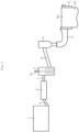
FIG. 1 is a side view for illustrating a manufacturing apparatus for a glass article according to a first embodiment of the present invention. -
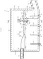
FIG. 2 is a sectional view of a melting furnace. -
FIG. 3 is a sectional view taken along the line I-I ofFIG. 2 . -
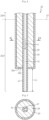
FIG. 4 is an enlarged sectional view of a nozzle of a liquid-surface height measurement device and therearound. -
FIG. 5 is a sectional view taken along the line II-II ofFIG. 4 . -
FIG. 6 is an enlarged view of a nozzle of a liquid-surface height measurement device according to a second embodiment of the present invention and therearound. -
FIG. 7 is a sectional view of a melting furnace according to a third embodiment of the present invention. - Now, embodiments of the present invention are described with reference to the attached drawings. Overlapping description may be omitted by denoting corresponding constituent elements in the embodiments by the same reference symbols. When only part of a configuration is described in each of the embodiments, a configuration in other embodiments that has already been described may be adopted for other parts of the configuration. In addition, configurations may be combined in a combination explicit in the description of each of the embodiments, and not only that, part of configurations of a plurality of the embodiments may be combined in an even implicit combination as long as the combination has no particular disadvantage.
- As illustrated in
FIG. 1 , a manufacturing apparatus for a glass article according to a first embodiment comprises: a meltingfurnace 1; a finingbath 2; a homogenization bath (stirring bath) 3; a pot 4; a formingbody 5; andtransfer pipes 6 to 9 that connect thoseconstituent elements 1 to 5 to each other. - The
melting furnace 1 is a space for performing a melting step of obtaining a molten glass Gm. Themelting furnace 1 functions as a storage tank for storing the molten glass Gm. - The fining
bath 2 is a space for performing a fining step of fining (degassing) the molten glass Gm supplied from themelting furnace 1 through the action of a fining agent or the like. - The
homogenization bath 3 is a space for performing a homogenization step of stirring, with astirrer 3a, the molten glass Gm having been fined to homogenize the molten glass Gm. Thehomogenization bath 3 may comprise a plurality of homogenization baths connected to one another. - The pot 4 is a space for performing a state adjustment step of adjusting the state (for example, viscosity) of the molten glass Gm so as to be suitable for forming. The pot 4 may be omitted.
- The forming
body 5 forms a forming device, and is a component for performing a forming step of forming the molten glass Gm into a desired shape. In this embodiment, the formingbody 5 is configured to form the molten glass Gm into a strip-shaped glass ribbon by an overflow down-draw method. - The forming
body 5 has a substantially wedge shape in a sectional shape (sectional shape perpendicular to the drawing sheet), and has an overflow groove (not shown) formed in an upper portion thereof. The molten glass Gm is supplied to the overflow groove through thetransfer pipe 9. The molten glass Gm supplied to the overflow groove overflows from the overflow groove and flows down along both side wall surfaces (side surfaces located on a front surface side and a back surface side of the drawing sheet) of the formingbody 5. The molten glass Gm flowing down along the side wall surfaces join each other at lower end portions of the side wall surfaces, and is formed into a strip-shaped glass ribbon Gr. The glass ribbon Gr having been formed is subjected to treatments, such as annealing and cutting, to thereby manufacture, as the glass article, a glass sheet or a glass roll in which the glass ribbon is taken up. - A thickness of the glass ribbon Gr (thickness of a central portion (small-thickness portion) in a width direction except for edge portions (large-thickness portions) at both ends in the width direction) is, for example, preferably from 0.01 mm to 2 mm, more preferably from 0.1 mm to 1 mm.
- The glass sheet or the glass roll is utilized for a display (for example, a liquid crystal display or an organic EL display), a substrate of an organic EL illumination or a solar cell, or a protective cover.
- The forming device is not limited to a device for performing the overflow down-draw method. For example, the forming device may be a device for performing any other down-draw method, such as a slot down-draw method, or a float method.
- The
transfer pipes 6 to 9 are each formed of, for example, a tubular pipe made of platinum or a platinum alloy, and are each configured to transfer the molten glass Gm in a lateral direction (substantially horizontal direction). Thetransfer pipes 6 to 9 are heated through application of a current as required. The platinum comprises strengthened platinum, and the platinum alloy comprises a strengthened platinum alloy (the same applies hereinafter). - As illustrated in
FIG. 2 andFIG. 3 , themelting furnace 1 comprises a bottom wall 1a, aside wall 1b, and aceiling wall 1c. Those constituent elements 1a to 1c define a space for storing the molten glass Gm. Theside wall 1b comprises a front wall 1b1, a rear wall 1b2, a left wall 1b3, and a right wall 1b4. - The
melting furnace 1 is configured to continuously melt glass raw materials Ga to form the molten glass Gm. The glass raw materials Ga may comprise cullet in addition to a natural raw material and a chemical raw material. It is preferred that the molten glass Gm be alkali-free glass or aluminosilicate glass for chemical strengthening. - A
feed port 10 for feeding the glass raw materials Ga is formed in the front wall 1b1 of themelting furnace 1. Ascrew feeder 11 serving as a raw material supply part is provided in thefeed port 10. The raw material supply part may be other publicly known part, such as a pusher or a vibrating feeder. The number or arrangement position of the raw material supply part may be appropriately changed depending on the size of themelting furnace 1, or the like. - An
outflow port 12 for allowing outflow of the molten glass Gm is formed in the rear wall 1b2 of themelting furnace 1. Thetransfer pipe 6 is connected to theoutflow port 12 so that the molten glass Gm is supplied sequentially to a downstream side. - A plurality of rod-shaped
electrodes 13 are mounted to the bottom wall 1a of themelting furnace 1. The shape of theelectrode 13 is not limited to a rod shape, and may be a sheet shape, a block shape, or a combination thereof. The mounting positions of theelectrodes 13 are not limited to the bottom wall 1a, and theelectrodes 13 may be mounted to the left wall 1b3 and the right wall 1b4. Theelectrode 13 is made of, for example, molybdenum (Mo). Theelectrodes 13 heat the molten glass Gm through application of a current in a state of being immersed in the molten glass Gm. Theelectrodes 13 pass through through holes formed in the bottom wall 1a in a state of being held incylindrical electrode holders 14, each comprising a cooling mechanism (not shown). A heating method used in themelting furnace 1 is not limited to all-electric melting using only heating through application of a current, and may be, for example, a heating method using only combustion (burner) of a gas fuel, which is performed from above a liquid surface LS of the molten glass Gm, or a heating method using a combination of heating through application of a current and combustion of a gas fuel. - As illustrated in
FIG. 3 , themelting furnace 1 comprises a liquid-surfaceheight measurement device 21 configured to measure a height H1 of the liquid surface LS of the molten glass Gm. The height H1 of the liquid surface LS of the molten glass Gm is defined based on a height position of a distal end of anozzle 22 as a reference (zero level). - The liquid-surface
height measurement device 21 comprises thenozzle 22, apipe 23, agas supply part 24, and apressure gauge 25. - The
nozzle 22 generates, from its distal end, air bubbles B in the molten glass Gm. Thenozzle 22 is immersed from above the liquid surface LS into the molten glass Gm. Thenozzle 22 has a substantially vertical posture, and comprises afirst part 22a and asecond part 22b. Thefirst part 22a is positioned below the liquid surface LS and is immersed in the molten glass Gm. Thesecond part 22b is positioned above the liquid surface LS and is not immersed in the molten glass Gm. Thefirst part 22a comprises the distal end portion of thenozzle 22, and thesecond part 22b comprises a proximal end portion of thenozzle 22. Thenozzle 22 may have an inclined posture. - The
pipe 23 allows supply of a gas A for generating the air bubbles B to thenozzle 22. The gas A is supplied into thepipe 23 from the gas supply part (for example, compressor) 24. Thepipe 23 is led, with a substantially horizontal posture, from an outside of themelting furnace 1 into themelting furnace 1 through a transverse hole X1 that is formed in theside wall 1b (left wall 1b3 in the illustrated example) of themelting furnace 1 at a position higher than the liquid surface LS. Thepipe 23 led into themelting furnace 1 is bent downward so as to change its posture from the substantially horizontal posture into a substantially vertical posture in a space above the liquid surface LS, and is connected to the proximal end portion of thenozzle 22, which is positioned above the liquid surface LS. That is, thepipe 23 is not in contact with the molten glass Gm. - Specifically, the
pipe 23 comprises a firststraight part 23a, a secondstraight part 23b, and a thirdstraight part 23c. The firststraight part 23a extends in a substantially horizontal direction. The secondstraight part 23b extends in a substantially vertical direction. The thirdstraight part 23c is provided between the firststraight part 23a and the secondstraight part 23b, and is inclined downward from the firststraight part 23a to reach the secondstraight part 23b. The firststraight part 23a is arranged so as to extend between an inside and the outside of themelting furnace 1 through the transverse hole X1 in theside wall 1b. The secondstraight part 23b and the thirdstraight part 23c are arranged in themelting furnace 1. The shape of thepipe 23 is not limited to any particular shape. Thepipe 23 may be formed by, for example, coupling the firststraight part 23a and the secondstraight part 23b to each other to define a substantially right angle without comprising the thirdstraight part 23c or may comprise a curved part in place of the thirdstraight part 23c. - The transverse hole X1 for allowing passage of the
pipe 23 may be a hole additionally formed at a position on theside wall 1b, which is higher than the liquid surface LS. For example, when transverse holes such as observation windows for observation of an inside of the furnace are already formed at positions on theside wall 1b, which are higher than the liquid surface LS, those existing transverse holes may be used. When a gap is defined between thepipe 23 and the transverse hole X1 under a state in which thepipe 23 is inserted through the transverse hole X1, a blanket, a refractory or the like may be arranged in the gap so as to fill the gap. - The
nozzle 22 and thepipe 23 are integrated with each other through connection. Thenozzle 22 is held at a predetermined height by thepipe 23. That is, besides thepipe 23, a member that holds thenozzle 22 is not provided in themelting furnace 1. Thepipe 23 and thenozzle 22 can be inserted into and removed from themelting furnace 1 through the transverse hole X1. In this embodiment, thepipe 23 is held by a holdingmember 26 outside themelting furnace 1. - The transverse hole X1 through which the
pipe 23 is to be inserted is positioned above the liquid surface LS of the molten glass Gm. Thus, leakage of the molten glass Gm from the transverse hole X1 to the outside does not substantially occur. Thus, the liquid-surfaceheight measurement device 21 can easily be maintained and easily be applied to an existingmelting furnace 1. - The
pressure gauge 25 is configured to measure a pressure (back pressure) in thepipe 23 or thenozzle 22 when the air bubbles B are generated in the molten glass Gm with the gas A supplied from the distal end of thenozzle 22. Thepipe 23 and thenozzle 22 form one gas supply path. Thus, the pressure in thepipe 23 and the pressure in thenozzle 22 are substantially the same. Thus, any of the pressure in thepipe 23 and the pressure in thenozzle 22 may be measured. In this embodiment, thepressure gauge 25 measures the pressure in thepipe 23 outside themelting furnace 1. - In the liquid-surface
height measurement device 21, the height H1 of the liquid surface LS of the molten glass Gm is determined in the following manner. - When the height H1 of the liquid surface LS of the molten glass Gm is to be measured, the liquid-surface
height measurement device 21 generates the air bubbles B in the molten glass Gm from the distal end of thenozzle 22. Timing of generation of the air bubbles B coincides with a time at which a pressure P1 in thepipe 23 and in thenozzle 22 becomes substantially equal to a sum (P2+P3) of a pressure P2 at the liquid surface LS of the molten glass Gm and a pressure P3 of the molten glass Gm at the height position of the distal end portion of thenozzle 22. That is, relationships expressed by Expressions (1) to (3) are established among the pressures described above. In Expressions, ρ represents a density of the molten glass Gm, and "g" represents a gravitational acceleration.


- Thus, when a differential pressure (P1-P2) between the pressure P1 in the
pipe 23 and the pressure P2 at the liquid surface LS of the molten glass Gm is measured, the height H1 of the liquid surface LS of the molten glass Gm can be calculated from Expression (3). - In this embodiment, the
pressure gauge 25 is formed of a differential pressure gauge (for example, a gauge pressure meter). Here, the pressure P2 at the liquid surface LS of the molten glass Gm inside themelting furnace 1 is sometimes adjusted to be higher than or lower than an atmospheric pressure PA. Even in those cases, however, a difference between the pressure P2 at the liquid surface LS of the molten glass Gm and the atmospheric pressure PA is slight, and thus the pressure P2 and the atmospheric pressure PA can be regarded as being substantially equal to each other. Thus, in this embodiment, thepressure gauge 25 is configured to measure a differential pressure (P1-PA) between the pressure P1 in thepipe 23 and the atmospheric pressure PA in place of measuring the differential pressure (P1-P2) between the pressure P1 in thepipe 23 and the pressure P2 at the liquid surface LS of the molten glass Gm. Then, the measurement of the differential pressure (P1-PA) allows the calculation of the height H1 of the liquid surface LS of the molten glass Gm from Expression (4).
- The
pressure gauge 25 may be configured to measure the differential pressure (P1-P2). Thepressure gauge 25 may be an absolute pressure gauge capable of individually measuring the pressures required for the calculation of the height H1. The liquid-surfaceheight measurement device 21 may comprise a computing part configured to automatically compute the height H1 of the liquid surface LS of the molten glass Gm according to Expression (3) or (4). Further, a height difference H2 between the bottom wall 1a and the height position of the distal end of thenozzle 22 can be measured in advance or set to a specified value. Thus, a height (H1+H2) of the liquid surface LS of the molten glass Gm from the bottom wall 1a serving as a reference (zero level) can also be determined. - As illustrated in
FIG. 4 and FIG. 5 , thenozzle 22 comprises apipe portion 27, a fire-resistant layer 28, and aprotective layer 29. - The
pipe portion 27 is a tubular body made of platinum or a platinum alloy and has an inside S1 through which the gas A is to flow. When thepipe portion 27 is made of platinum or a platinum alloy as described above, damage and wear of thepipe portion 27 due to heat or erosion of thepipe portion 27 by the molten glass Gm can be suppressed. - The fire-
resistant layer 28 is a layer being made of a refractory and covering thepipe portion 27. With the fire-resistant layer 28 being provided in this manner, strength of thenozzle 22 can be improved. Thus, deformation of the nozzle 22 (precisely, the pipe portion 27) under a force (for example, upward force) from the glass raw materials Ga, the molten glass Gm, or the like at the time of, for example, immersion into the molten glass Gm can be suppressed. As the refractory for forming the fire-resistant layer 28, for example, a brick or an unshaped refractory may be used. As the brick, for example, a zirconia-based electrocast brick, an alumina-based electrocast brick, an alumina-zirconia-based electrocast brick, an AZS (Al-Zr-Si)-based electrocast brick, or high-purity alumina (for example, alumina pipe) may be used. As the unshaped refractory, for example, refractory cement such as alumina cement may be used. - The
protective layer 29 is a layer made of platinum or a platinum alloy for covering the fire-resistant layer 28. With the protective layer being provided in this manner, the erosion of the fire-resistant layer 28 by the molten glass Gm can be suppressed. - A distal end portion of the
pipe portion 27 is not covered with the fire-resistant layer 28 or theprotective layer 29, and is exposed. That is, the distal end portion of thepipe portion 27 protrudes downward beyond a distal end portion of the fire-resistant layer 28 and a distal end portion of theprotective layer 29. A protrusion amount L1 of the exposed distal end portion of thepipe portion 27 is, for example, preferably from 10 mm to 200 mm, more preferably from 50 mm to 100 mm. An outer diameter of the exposedpipe portion 27 is, for example, preferably from 10 mm to 50 mm, more preferably from 10 mm to 30 mm. The distal end of the fire-resistant layer 28 and the distal end of theprotective layer 29 respectively compriseflat surface portions pipe portion 27. When thepipe portion 27 has the distal end portion being exposed as described above, an outer diameter of the distal end portion of thenozzle 22 can be reduced. Hence, the air bubbles B are less liable to stagnate around the distal end portion of thenozzle 22. Thus, when the air bubbles B are generated from the distal end portion of thenozzle 22, the back pressure is properly exerted in thenozzle 22 or thepipe 23. As a result, measurement accuracy for the height H1 of the liquid surface LS is improved. - Although not shown, the
pipe 23 comprises an inner pipe and a cooling structure. The gas A for generating the air bubbles B in the molten glass Gm flows through the inner pipe. The cooling structure is arranged so as to cover the inner pipe. The inner pipe and the cooling structure can be made of, for example, stainless steel or heat-resistant steel. - A proximal end portion of the inner pipe is in communication with the
gas supply part 24. A distal end portion of the inner pipe is in communication with a proximal end portion of thepipe portion 27 of thenozzle 22. Thus, the gas A supplied from thegas supply part 24 flows through an inside of the inner pipe of thepipe 23, flows through the inside S1 of thepipe portion 27 of thenozzle 22, and is then discharged into the molten glass Gm. - The cooling structure comprises a flow passage through which refrigerant supplied to and discharged from the outside is to flow. Thus, damage and wear due to heat of the pipe 23 (inner pipe) can be prevented.
- Now, a method of manufacturing a glass article using the manufacturing apparatus having the above-mentioned configuration is described.
- The method comprises: a melting step; a molten-glass supply step; a forming step; an annealing step; and a cutting step.
- In the melting step, the glass raw materials Ga supplied into the
melting furnace 1 are heated to produce the molten glass Gm. The liquid surface LS of the molten glass Gm may be covered with a covering layer Gx. The covering layer Gx comprises the glass raw materials Ga and/or a foam layer Gb. The foam layer Gb is formed along with the generation of a carbon oxide gas (CO or CO2), an O2 gas, an SO2 gas or the like from the glass raw materials Ga. Heat dissipation from the molten glass Gm can be suppressed by covering the liquid surface LS of the molten glass Gm with the covering layer Gx as described above. As a result, a temperature of the molten glass Gm can be reliably maintained, and hence energy saving can be achieved. The foam layer Gb may be omitted. - The melting step further comprises a liquid-surface height measurement step of measuring the height of the liquid surface LS of the molten glass Gm stored in the
melting furnace 1. In the liquid-surface height measurement step, the height of the liquid surface LS is measured by using the liquid-surfaceheight measurement device 21. Specifically, the gas A is supplied to thenozzle 22 through thepipe 23 so that the air bubbles B are generated in the molten glass Gm from the distal end of thenozzle 22. Then, the differential pressure (P1-PA) between the pressure P1 in the nozzle 22 (pipe portion 27) or thepipe 23 and the atmospheric pressure PA at the time of generation of the air bubbles B is measured with thepressure gauge 25. The height H1 of the liquid surface LS is calculated based on the measured differential pressure (P1-PA) from Expression (4). - In the molten-glass supply step, the molten glass Gm in the
melting furnace 1 is transferred sequentially to the finingbath 2, thehomogenization bath 3, the pot 4, and the formingbody 5 via thetransfer pipes 6 to 9. In the finingbath 2, the molten glass Gm is subjected to fining (bubble removal) by the action of a fining agent or the like (fining step). In thehomogenization bath 3, the molten glass Gm is stirred to be homogenized (homogenization step). In the pot 4, a state (for example, a viscosity or a flow rate) of the molten glass Gm is adjusted (state adjustment step). - In the forming step after the molten-glass supply step, the molten glass Gm is supplied to the forming
body 5. The formingbody 5 causes the molten glass Gm to overflow from the overflow groove to flow down along the side wall surfaces of the formingbody 5. The formingbody 5 causes the molten glasses Gm having flowed down to join each other at lower end portions to thereby form the glass ribbon Gr. - After that, in the annealing step, the glass ribbon Gr is cooled in an annealing furnace. In the cutting step, the glass ribbon Gr is cut by a cutting device. As a result, a glass sheet having predetermined dimensions is cut out from the glass ribbon Gr. Alternatively, after both end portions (edge portions) of the glass ribbon Gr in the width direction are removed in the cutting step, the glass ribbon Gr may be taken up into a roll to thereby obtain a glass roll (take-up step).
- As illustrated in
FIG. 6 , in a second embodiment, a modification example of thenozzle 22 of the liquid-surface measurement device 21 is exemplified. - As illustrated in
FIG. 6 , in this embodiment, anozzle 22 comprises, as in the first embodiment, apipe portion 27, a fire-resistant layer 28, and aprotective layer 29. A distal end portion of thepipe portion 27 is not covered with the fire-resistant layer 28 or theprotective layer 29, and is exposed. That is, the distal end portion of thepipe portion 27 protrudes downward beyond a distal end portion of the fire-resistant layer 28 and a distal end portion of theprotective layer 29. - Meanwhile, as a difference from the first embodiment, the distal end portion of the fire-
resistant layer 28 and the distal end portion of theprotective layer 29 comprise taperedportions tapered portions tapered portions portions nozzle 22, and measurement accuracy for a height H1 of a liquid surface LS is further improved. Further, a force that thenozzle 22 receives from the glass raw materials Ga, the molten glass Gm, or the like at the time of, for example, immersion into the molten glass Gm can be reduced, and hence thenozzle 22 can be smoothly immersed into the molten glass. - An inclination angle θ of the tapered
portions - As illustrated in
FIG. 7 , in a third embodiment, a modification example of thepipe 23 of the liquid-surface measurement device 21 is exemplified. - In this embodiment, a
pipe 23, which has a substantially vertical posture, is led from an outside of amelting furnace 1 into themelting furnace 1 through a longitudinal hole X2 formed in aceiling wall 1c of themelting furnace 1 at a position higher than a liquid surface LS. Thepipe 23 led into themelting furnace 1 is connected to a proximal end portion of anozzle 22, which is positioned above the liquid surface LS, while maintaining the substantially vertical posture. A distal end portion side of thenozzle 22 is immersed from above the liquid surface LS into a molten glass Gm. - Here, when the
pipe 23 is led from the outside of themelting furnace 1 into themelting furnace 1 through the longitudinal hole X2 in theceiling wall 1c, a length of thepipe 23 has a tendency to be longer than in a case in which thepipe 23 is led from the outside of themelting furnace 1 into themelting furnace 1 through the transverse hole X1 in theside wall 1b. Thus, in terms of reduction in facility costs, as described in the first embodiment, it is preferred that thepipe 23 be led from the outside of themelting furnace 1 into themelting furnace 1 through the transverse hole X1 in theside wall 1b. - The present invention is not limited to the configurations of the above-mentioned embodiments. In addition, the action and effect of the present invention are not limited to those described above. The present invention may be modified in various forms within the range not departing from the spirit of the present invention.
- In the embodiments, a glass sheet and a glass roll have been exemplified as the glass article. However, the glass article may be, for example, a glass sphere, a glass tube, a glass block, a glass fiber, or the like, and may have other appropriate shapes.
- In the embodiments, the measurement of the height of the liquid surface of the molten glass stored in the melting furnace has been described. The present invention is also applicable to measurement of a height of a liquid surface of a molten glass stored in a storage tank other than the melting furnace, such as a feeder connected to the melting furnace or a fining bath having furnace walls made of a refractory. In a case of a manufacturing apparatus for a glass fiber, the feeder comprises a bushing including a plurality of nozzles for forming a glass fiber from a molten glass.
-
- 1
- melting furnace
- 1a
- bottom wall
- 1b
- side wall
- 1c
- ceiling wall
- 2
- fining bath
- 3
- homogenization bath
- 4
- pot
- 5
- forming body
- 6 to 9
- transfer pipe
- 10
- feed port
- 11
- screw feeder
- 12
- outflow port
- 13
- electrode
- 14
- electrode holder
- 21
- measurement device
- 22
- nozzle
- 23
- pipe
- 24
- gas supply part
- 25
- pressure gauge
- 26
- holding member
- 27
- pipe portion
- 28
- fire-resistant layer
- 29
- protective layer
- A
- gas
- B
- bubble
- Ga
- glass raw material
- Gb
- foam layer
- Gm
- molten glass
- Gr
- glass ribbon
- Gx
- covering layer
- LS
- liquid surface of molten glass
- X1
- transverse hole (side wall)
- X2
- longitudinal hole (ceiling wall)
Claims (9)
- A manufacturing apparatus for a glass article, comprising:a storage tank configured to store a molten glass; anda liquid-surface height measurement device configured to measure a height of a liquid surface of the molten glass stored in the storage tank,wherein the liquid-surface height measurement device comprises:a nozzle to be immersed from above the liquid surface into the molten glass;a pipe, which is led from an outside of the storage tank into the storage tank at a position higher than the liquid surface and is configured to allow supply of a gas to the nozzle; anda pressure gauge configured to measure a pressure in the pipe or the nozzle.
- The manufacturing apparatus for a glass article according to claim 1, wherein the pipe is led from the outside of the storage tank into the storage tank through a hole formed in a side wall of the storage tank.
- The manufacturing apparatus for a glass article according to claim 1 or 2, wherein the nozzle is held at a predetermined height by the pipe.
- The manufacturing apparatus for a glass article according to claim 1 or 2, wherein the pipe comprises a cooling structure.
- The manufacturing apparatus for a glass article according to claim 1 or 2, wherein the nozzle comprises a pipe portion made of platinum or a platinum alloy, through which the gas is to flow.
- The manufacturing apparatus for a glass article according to claim 5, wherein the nozzle comprises:a fire-resistant layer being made of a refractory and covering the pipe portion; anda protective layer being made of platinum or a platinum alloy and covering the fire-resistant layer.
- The manufacturing apparatus for a glass article according to claim 6, wherein a distal end portion of the pipe portion is free from being covered with the fire-resistant layer, and is exposed.
- A liquid-surface height measurement method of measuring a height of a liquid surface of a molten glass stored in a storage tank, the method comprising:providing: a nozzle to be immersed from above the liquid surface into the molten glass; and a pipe, which is led from an outside of the storage tank into the storage tank at a position higher than the liquid surface, and is configured to allow supply of a gas to the nozzle; anddetermining the height of the liquid surface based on a pressure in the pipe or the nozzle.
- A manufacturing method for a glass article, comprising a liquid-surface height measurement step of measuring a height of a liquid surface of a molten glass stored in a storage tank,
wherein, in the liquid-surface height measurement step, the height of the liquid surface is measured by the method of claim 8.
Applications Claiming Priority (2)
| Application Number | Priority Date | Filing Date | Title |
|---|---|---|---|
| JP2022123289 | 2022-08-02 | ||
| PCT/JP2023/026103 WO2024029317A1 (en) | 2022-08-02 | 2023-07-14 | Device and method for producing glass article and method for measuring liquid-surface height |
Publications (2)
| Publication Number | Publication Date |
|---|---|
| EP4538240A1 true EP4538240A1 (en) | 2025-04-16 |
| EP4538240A4 EP4538240A4 (en) | 2025-11-19 |
Family
ID=89848764
Family Applications (1)
| Application Number | Title | Priority Date | Filing Date |
|---|---|---|---|
| EP23849876.0A Pending EP4538240A4 (en) | 2022-08-02 | 2023-07-14 | DEVICE AND METHOD FOR MANUFACTURING A GLASS ARTICLE AND METHOD FOR MEASURING THE HEIGHT OF A LIQUID SURFACE |
Country Status (5)
| Country | Link |
|---|---|
| US (1) | US20260015277A1 (en) |
| EP (1) | EP4538240A4 (en) |
| JP (1) | JPWO2024029317A1 (en) |
| CN (1) | CN119585216A (en) |
| WO (1) | WO2024029317A1 (en) |
Family Cites Families (12)
| Publication number | Priority date | Publication date | Assignee | Title |
|---|---|---|---|---|
| US2737807A (en) * | 1950-09-07 | 1956-03-13 | Union Des Verreries Mecaniques | Apparatus for measuring the level of the molten glass in tank furnaces |
| GB1154217A (en) * | 1966-11-25 | 1969-06-04 | Pilkington Brothers Ltd | Apparatus for Measuring the Height of the Surface of a Liquid |
| US3494191A (en) * | 1968-04-05 | 1970-02-10 | Corning Glass Works | Fluid driven surface level sensing system |
| JPS5740699A (en) * | 1980-08-26 | 1982-03-06 | Doryokuro Kakunenryo | Method of grasping radioactive waste furnace state |
| US5868814A (en) * | 1997-09-22 | 1999-02-09 | Gts Duratek, Inc. | Apparatus for recirculating molten glass |
| US6334337B1 (en) * | 1999-08-17 | 2002-01-01 | Pedro Buarque de Macedo | Air bubbler to increase glass production rate |
| JP2007131515A (en) * | 2005-10-14 | 2007-05-31 | Ohara Inc | Glass production device and glass production method |
| CN208802981U (en) * | 2018-09-05 | 2019-04-30 | 咸宁南玻玻璃有限公司 | A glass furnace liquid level monitoring system |
| US11505486B2 (en) * | 2019-10-08 | 2022-11-22 | Owens-Brockway Glass Container Inc. | Verifiable bubbler |
| JP7505174B2 (en) * | 2019-10-18 | 2024-06-25 | 日本電気硝子株式会社 | Apparatus and method for manufacturing glass articles |
| JP7602725B2 (en) | 2020-03-19 | 2024-12-19 | 日本電気硝子株式会社 | Glass depth measuring method, bubble layer depth measuring method, and glass melting furnace |
| CN113880424A (en) * | 2021-09-28 | 2022-01-04 | 河海大学 | Crucible pressurization adjusting device and method for producing glass fibers |
-
2023
- 2023-07-14 CN CN202380055122.8A patent/CN119585216A/en active Pending
- 2023-07-14 JP JP2024538903A patent/JPWO2024029317A1/ja active Pending
- 2023-07-14 US US18/994,312 patent/US20260015277A1/en active Pending
- 2023-07-14 EP EP23849876.0A patent/EP4538240A4/en active Pending
- 2023-07-14 WO PCT/JP2023/026103 patent/WO2024029317A1/en not_active Ceased
Also Published As
| Publication number | Publication date |
|---|---|
| EP4538240A4 (en) | 2025-11-19 |
| CN119585216A (en) | 2025-03-07 |
| JPWO2024029317A1 (en) | 2024-02-08 |
| WO2024029317A1 (en) | 2024-02-08 |
| US20260015277A1 (en) | 2026-01-15 |
Similar Documents
| Publication | Publication Date | Title |
|---|---|---|
| US8857219B2 (en) | Apparatus for use in direct resistance heating of platinum-containing vessels | |
| JP5397371B2 (en) | Molten glass manufacturing apparatus and molten glass manufacturing method using the same | |
| US11505487B2 (en) | Method for decreasing bubble lifetime on a glass melt surface | |
| US20200095152A1 (en) | Methods and apparatuses for controlling glass flow into glass forming machines | |
| KR101341741B1 (en) | Method for producing molten glass, vacuum degassing apparatus, and method for producing glass product | |
| JP2019510977A (en) | Method and apparatus for thermocouple of molten material | |
| KR20190077586A (en) | Method and Apparatus for Regulating Glass Ribbons | |
| JP7602725B2 (en) | Glass depth measuring method, bubble layer depth measuring method, and glass melting furnace | |
| KR102509016B1 (en) | Apparatus and method for conditioning molten glass | |
| US20260015277A1 (en) | Device and method for producing glass article and method for measuring liquid-surface height | |
| KR20190045864A (en) | Glass melting furnace and method for producing glass articles | |
| US20210130214A1 (en) | Method for manufacturing glass article, and melting furnace | |
| KR101798288B1 (en) | Method and apparatus for making glass substrate | |
| TW201111312A (en) | Molten glass manufacturing device, molten glass manufacturing method, and sheet glass manufacturing method using the device and the method | |
| WO2021117618A1 (en) | Melted glass transport device, glass article manufacturing device, and glass article manufacturing method | |
| JP5751252B2 (en) | Molten glass feeder | |
| CN116639863A (en) | Glass melting furnace and melting vessel with improved thermal properties | |
| JP5454535B2 (en) | Sheet glass manufacturing method and manufacturing apparatus | |
| JP2003292323A (en) | Glass melting furnace and glass melting method | |
| CN104788010B (en) | Float glass manufacturing device and float glass making process | |
| US20190084860A1 (en) | Alkali-free glass substrate | |
| EP4606778A1 (en) | Manufacturing method and manufacturing device of glass article | |
| TW201945299A (en) | Exhaust conduits for glass melt systems | |
| CN118984814A (en) | Method for manufacturing glass articles | |
| KR20160001275A (en) | Apparatus for manufacturing glass and method for manufacturing glass using the same |
Legal Events
| Date | Code | Title | Description |
|---|---|---|---|
| STAA | Information on the status of an ep patent application or granted ep patent |
Free format text: STATUS: THE INTERNATIONAL PUBLICATION HAS BEEN MADE |
|
| PUAI | Public reference made under article 153(3) epc to a published international application that has entered the european phase |
Free format text: ORIGINAL CODE: 0009012 |
|
| STAA | Information on the status of an ep patent application or granted ep patent |
Free format text: STATUS: REQUEST FOR EXAMINATION WAS MADE |
|
| 17P | Request for examination filed |
Effective date: 20250108 |
|
| AK | Designated contracting states |
Kind code of ref document: A1 Designated state(s): AL AT BE BG CH CY CZ DE DK EE ES FI FR GB GR HR HU IE IS IT LI LT LU LV MC ME MK MT NL NO PL PT RO RS SE SI SK SM TR |
|
| DAV | Request for validation of the european patent (deleted) | ||
| DAX | Request for extension of the european patent (deleted) | ||
| A4 | Supplementary search report drawn up and despatched |
Effective date: 20251016 |
|
| RIC1 | Information provided on ipc code assigned before grant |
Ipc: C03B 5/16 20060101AFI20251010BHEP Ipc: C03B 5/167 20060101ALI20251010BHEP Ipc: G01F 23/16 20060101ALI20251010BHEP Ipc: G01F 23/14 20060101ALI20251010BHEP Ipc: G01F 23/18 20060101ALI20251010BHEP |