EP4538143A1 - Pocket wagon - Google Patents
Pocket wagon Download PDFInfo
- Publication number
- EP4538143A1 EP4538143A1 EP23210922.3A EP23210922A EP4538143A1 EP 4538143 A1 EP4538143 A1 EP 4538143A1 EP 23210922 A EP23210922 A EP 23210922A EP 4538143 A1 EP4538143 A1 EP 4538143A1
- Authority
- EP
- European Patent Office
- Prior art keywords
- wagon
- basket
- spurs
- outs
- Prior art date
- Legal status (The legal status is an assumption and is not a legal conclusion. Google has not performed a legal analysis and makes no representation as to the accuracy of the status listed.)
- Pending
Links
Images


Classifications
-
- B—PERFORMING OPERATIONS; TRANSPORTING
- B61—RAILWAYS
- B61D—BODY DETAILS OR KINDS OF RAILWAY VEHICLES
- B61D3/00—Wagons or vans
- B61D3/16—Wagons or vans adapted for carrying special loads
- B61D3/18—Wagons or vans adapted for carrying special loads for vehicles
- B61D3/182—Wagons or vans adapted for carrying special loads for vehicles specially adapted for heavy vehicles, e.g. public work vehicles, trucks, trailers
- B61D3/184—Wagons or vans adapted for carrying special loads for vehicles specially adapted for heavy vehicles, e.g. public work vehicles, trucks, trailers the heavy vehicles being of the trailer or semi-trailer type
-
- B—PERFORMING OPERATIONS; TRANSPORTING
- B61—RAILWAYS
- B61D—BODY DETAILS OR KINDS OF RAILWAY VEHICLES
- B61D3/00—Wagons or vans
- B61D3/16—Wagons or vans adapted for carrying special loads
- B61D3/20—Wagons or vans adapted for carrying special loads for forwarding containers
-
- B—PERFORMING OPERATIONS; TRANSPORTING
- B61—RAILWAYS
- B61D—BODY DETAILS OR KINDS OF RAILWAY VEHICLES
- B61D45/00—Means or devices for securing or supporting the cargo, including protection against shocks
- B61D45/001—Devices for fixing to walls or floors
- B61D45/004—Fixing semi-trailers
-
- B—PERFORMING OPERATIONS; TRANSPORTING
- B61—RAILWAYS
- B61D—BODY DETAILS OR KINDS OF RAILWAY VEHICLES
- B61D47/00—Loading or unloading devices combined with vehicles, e.g. loading platforms, doors convertible into loading and unloading ramps
- B61D47/005—Loading or unloading devices combined with road vehicles carrying wagons, e.g. ramps, turntables, lifting means
Definitions
- the object of the invention is a pocket wagon for transporting road trailers and containers.
- Combined road-rail transport uses tractor units with semi-trailers, which are then transported using specially adapted pocket wagons.
- pocket wagons have a loading platform supported on bogies. The lowered floor of the platform creates a pocket-like loading space in the axis of the bogies, in which the semi-trailers are placed using the cranes and other infrastructure located at the transhipment terminal.
- the main disadvantage of this solution is that the semi-trailer needs to be adapted for crane handling, in particular by reinforcing the semi-trailer frame particularly at the grab contact points. This involves a significant increase in production costs, so that the vast majority of trailers in use are not suitable for this form of transport. In addition, it complicates the issue of logistics, as it has to be taken into account at the very beginning of planning whether a trailer is to be used for combined transport.
- the second type of pocket wagons are wagons in which the pocket is rotated around the shaft. In this position, a trailer or semi-trailer can be slid directly onto the pocket.
- the disadvantage of this solution is the complexity of the wagon and the operating system, requiring skilled personnel and a lot of time.
- a pocket wagon consisting of a wagon spur, supported by support areas on bogies and connected to each other by two longitudinal beams, and a transport basket.
- the basket constitutes the floor of the pocket wagon and is positioned in the frame of the spur by suspending its structure on the longitudinal beams by means of tabs in the walls of the basket.
- the pocket wagon consists of at least one ostoy with two ostoy of irregular height, running in the middle at equal distances from the ostoy a dorsal beam connected to the ostoy by at least two crossbeams and a running gear in which is detachably placed a basket for a semi-trailer with a total width corresponding to the distance between the ostoy, the side walls and a tripartite floor composed of three strips parallel to each other.
- the essence of the solution according to the invention consists in the following:
- the crossbars have ends that curve upwards in two steps.
- the wagon with a single stand has a symmetrical design with respect to the transverse axis and is equipped with a running gear with an equal number of axles or bogies in the outermost parts of the wagon and collision devices on both faces.
- the central strip of the basket floor has axially aligned holes along its entire length.
- the main advantage of the solution according to the invention is the versatility of the wagon.
- the wagon can be used to transport both road trailers and containers.
- the semi-trailers themselves do not need to be adapted to lift a grab.
- the semi-trailer can be placed in a basket mounted on the spur by means of a crane or overhead crane, but can also be rolled into a basket set on the ground and then transferred in that basket to the spur.
- the wagon is designed to carry semi-trailers of different lengths, and the adjustable basket handles enable semi-trailers with different centres of gravity to be carried safely.
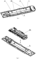
- Fig. 1 depicts an articulated wagon blade
- Fig. 2 a wagon blade with one blade with a basket
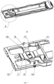
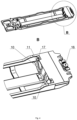
- Fig. 3 a front part of the blade
- Fig. 4 - rear part of the articulated wagon blade
- Fig. 5 wagon basket
- Fig. 6 container supports
- Fig. 7 articulated wagon with loaded road semi-trailers
- Fig. 8 road semi-trailer
- Fig. 9 articulated wagon with loaded container.
- a two-body wagon with two blades 1 is equipped with a running gear 5 with three bogies, in which case each blade 1 has one bogie at the end of the headstock 12 with a buffer device 13 and at the other end one common bogie for the two blades 1.
- each blade 1 is equipped at one end with a connecting fitting 16, to be connected to the other blade 1 and supported on a common bogie.
- two vertical side guides 18 each are attached to facilitate the insertion of the basket 20 into the pockets of the stays 1 and to stabilise the basket 20 across the wagon.
- the refuge 1 at the end opposite the headstock 12 with buffer devices 13 is equipped with connecting hardware 16 to connect to the other refuge 1 and support it on a common bogie.
- the stays 2 are also equipped on both sides with hooks 14 attached to their outer walls for shunting the wagons, located at the height of the torsion beam 8.
- the central chord 22' has a width greater than the width s of the dorsal beam 3 of the uprights 1 and less than the distance v between the wheels of the semi-trailer 32 and the truck tractor is provided at both ends with semicircular slides 23 to facilitate the insertion of the basket 20 into the pockets 6 of the uprights 1 and to stabilise it in the guides 10 of the uprights 1.
- the handle arm 25 translates by closing one or the other of the adjacent cut-outs 24 locking into the corresponding lock 30.
- bidirectional equal 26 overruns, the top of which is flush with the surface of the central lane 22'.
- the distance between the inner equal 26 is greater than the distance between the outermost wheels of the semi-trailer 32.
- mounting tunnels 27 are made in the floor of the basket 20, corresponding to the width of the crossbars 4 of the spur 1, which, when the basket 20 is placed on the spur 1, cover the crossbars 4 from above.
- the basket 20 is provided with side wall reinforcements 21, that is, longitudinal reinforcements 21 in the upper part of the wall 21' in the sections between the two central cut-outs 24 and vertical reinforcements 21 in the lower part of the wall 21' spaced evenly in series and located at the height of the attachment points of the handle arms 25.
- the loading of the semi-trailer 32 may be carried out by means of a crane or overhead crane, which carries it and lowers it into the basket 20 positioned on the spur 1.
- the crane may lift the basket 20 from the spur 1 and place it on the ground.
- the semi-trailer 32 is then rolled by the semi-trailer tractor to the basket 20, whereupon the position of the handle arms is adjusted to the centre of gravity of the semi-trailer 32.
- the basket 20 is then lifted by the crane or crane gripper hooked to the opposite handle arms 25 and transferred to the spur 1, where the basket 20 is stabilised in the pocket of the spur 1 by the semi-circular slides 23 in the guides 10 and the position stabilisers 28.
Landscapes
- Engineering & Computer Science (AREA)
- Transportation (AREA)
- Mechanical Engineering (AREA)
- Handcart (AREA)
Abstract
Description
- The object of the invention is a pocket wagon for transporting road trailers and containers.
- The essence of combined transport is the use of more than one form of transport to get a load from its origin to its destination. This is most often done by carrying the initial and final cargo unit by road and using rail or shipping for the middle leg.
- Combined road-rail transport uses tractor units with semi-trailers, which are then transported using specially adapted pocket wagons. In their basic version, pocket wagons have a loading platform supported on bogies. The lowered floor of the platform creates a pocket-like loading space in the axis of the bogies, in which the semi-trailers are placed using the cranes and other infrastructure located at the transhipment terminal. The main disadvantage of this solution is that the semi-trailer needs to be adapted for crane handling, in particular by reinforcing the semi-trailer frame particularly at the grab contact points. This involves a significant increase in production costs, so that the vast majority of trailers in use are not suitable for this form of transport. In addition, it complicates the issue of logistics, as it has to be taken into account at the very beginning of planning whether a trailer is to be used for combined transport.
- The second type of pocket wagons are wagons in which the pocket is rotated around the shaft. In this position, a trailer or semi-trailer can be slid directly onto the pocket. The disadvantage of this solution is the complexity of the wagon and the operating system, requiring skilled personnel and a lot of time.
- In order to solve the above problem and enable the use of any semi-trailers in combined transport, the pocket wagons are equipped with removable baskets in which the semi-trailers are placed and which can be removed and placed in the pockets by means of cranes or overhead cranes.
- From the description of the invention
EP3268257B1 , an example of the design of a load-bearing device - a basket - used for transporting semi-trailers on pocket wagons is known. - From the description of
EP1712444 , a pocket wagon is known, consisting of a wagon spur, supported by support areas on bogies and connected to each other by two longitudinal beams, and a transport basket. The basket constitutes the floor of the pocket wagon and is positioned in the frame of the spur by suspending its structure on the longitudinal beams by means of tabs in the walls of the basket. - A wagon for combined rail-rail transport is known from the description of the invention
EP1292477B1 . The wagon consists of two end platforms seated on rail bogies, connected to each other by a single longitudinal connecting element in the form of a beam. The connecting element serves in this configuration to stabilise the structure during loading and unloading. The load-bearing capacity of the wagon is provided by a basket structure superimposed on the platforms. The basket consists of the floor together with the elevated side edges and has the possibility to pivot about an end or central pivot centre. -
Polish patent application P. 294311 - From patent document
PL201606 - From patent document
PL235404 - From patent document
PL173864 - The pocket wagon consists of at least one ostoy with two ostoy of irregular height, running in the middle at equal distances from the ostoy a dorsal beam connected to the ostoy by at least two crossbeams and a running gear in which is detachably placed a basket for a semi-trailer with a total width corresponding to the distance between the ostoy, the side walls and a tripartite floor composed of three strips parallel to each other. The essence of the solution according to the invention consists in the following:
- the dorsal beam and the crossbeams of each stub support the basket floor in such a way that the outermost running straps of the basket floor are between the stubs and the dorsal beam, and the dorsal beam on at least one side of the stub passes through a torsion beam which is connected to the stubs, forming with it, at the point of connection, a saddle for the support bracket of the stub of the semi-trailer, into a coupling beam connected to the stubs by a headstock,
- the wagon pocket in the longitudinal axis is delimited by crossbeams connecting the dorsal beam to the stays, with two vertical guides attached to the crossbeams to facilitate the insertion of the basket into the pocket of the stays and to stabilise the loaded basket along the wagon axis,
- a basket the two outer running boards of which are of a width less than the distance between the rack and the dorsal beam of the rollstock, the intermediate upward flange between the two being of a width greater than the width of the dorsal beam of the rollstock and less than the distance between the wheels of the semi-trailer and the road tractor, and provided at both ends with semicircular slides cooperating with guides to facilitate insertion of the basket into the rollstock pocket and to stabilise the basket along the axle of the wagon, and in the upper parts of the side walls of the basket there are an even number of longitudinal open cut-outs, the parts of the upper walls of the basket between two adjacent cut-outs bearing pivoting longitudinal arms of handles, the length of which corresponds to the length of the cut-outs, the free ends of which are provided with catches for locking the handles into the locks located on opposite sides of the two adjacent cut-outs.
- Advantageously, the crossbars have ends that curve upwards in two steps. Advantageously, the wagon with a single stand has a symmetrical design with respect to the transverse axis and is equipped with a running gear with an equal number of axles or bogies in the outermost parts of the wagon and collision devices on both faces.
- Advantageously, the two-bay wagon has two spurs and is equipped with a six-axle running gear, each spur having one bogie on the side of the headstock with buffer device and one common bogie for the two spurs at the other end.
- Advantageously, the top edge of the crossbars bounding the wagon pocket is flush with the top edges of the uprights.
- Advantageously, the spur of a two-unit wagon is equipped at one end with connecting hardware to connect to the other spur and support it on a common bogie.
- In an advantageous design, at the upper edges of the torsion beam wall on the side of the transverse beam delimiting the wagon pocket, there are line-bearing container pins, locked in the operating position by a bolt in a hole made in the torsion beam flange and having on their upper surface pins on which containers are seated by means of holes made in the lower corners. In an advantageous design, at the upper edges of the crossbar delimiting the wagon pocket on the side of the centre of the spur there are linear-bearing container supports, locked in the working position by a pin in a hole made in the shelf of the crossbar delimiting the wagon pocket and having on the upper surface pins on which containers are seated by holes made in the lower corners.
- Advantageously, the central strip of the basket floor has axially aligned holes along its entire length.
- Advantageously, at both ends of the running lanes, there are elevated two-way equal inrunners, the top of which is flush with the surface of the central lane and the distance between the inner equal inrunners is greater than the distance between the outermost wheels of the semi-trailer, while underneath the equal inrunners, mounting tunnels are made in the floor of the basket, corresponding to the width of the cross-members of the spurs. Advantageously, there are stabilising brackets at the ends of the side walls of the basket.
- Advantageously, in the lower parts of the side wall of the basket, there are evenly spaced vertical reinforcements in series located at the level of the attachment points of the handle arms.
- In the favourable design, the side walls of the basket have, in the sections between the two central cut-outs, longitudinal reinforcements.
- The main advantage of the solution according to the invention is the versatility of the wagon. The wagon can be used to transport both road trailers and containers. Importantly, the semi-trailers themselves do not need to be adapted to lift a grab. The semi-trailer can be placed in a basket mounted on the spur by means of a crane or overhead crane, but can also be rolled into a basket set on the ground and then transferred in that basket to the spur. The wagon is designed to carry semi-trailers of different lengths, and the adjustable basket handles enable semi-trailers with different centres of gravity to be carried safely.
- The solution according to the invention is illustrated by the manufacturing examples shown in the figure, where
Fig. 1 depicts an articulated wagon blade,Fig. 2 - a wagon blade with one blade with a basket ,Fig. 3 - front part of the blade,Fig. 4 - rear part of the articulated wagon blade,Fig. 5 - wagon basket,Fig. 6 - container supports,Fig. 7 - articulated wagon with loaded road semi-trailers,Fig. 8 - road semi-trailer,Fig. 9 - articulated wagon with loaded container. - The wagon according to the invention consists of one or two inseparably connected
spurs 1. Eachspur 1 hasspurs 2 of irregular height, running at equal distances t from the spurs 1 adorsal beam 3 connected to thespurs 2 by twocrossbeams 4, with ends curved two degrees upwards. The wagon with onestand 1 is of symmetrical construction with respect to the transverse axis and is equipped with a runninggear 5 with an equal number of axles or bogies in the outermost parts of the wagon andcollision devices 13 on bothheadboards 12. A two-body wagon with twoblades 1 is equipped with a runninggear 5 with three bogies, in which case eachblade 1 has one bogie at the end of theheadstock 12 with abuffer device 13 and at the other end one common bogie for the twoblades 1. In a two-body wagon, eachblade 1 is equipped at one end with a connecting fitting 16, to be connected to theother blade 1 and supported on a common bogie. - The
dorsal beam 3 on at least one side of thespur 1 passes through alocking step 6 into atorsion beam 8, which is connected to thespurs 2, forming asaddle 9 at the connection point for the supportingbracket 15 of thekingpin 33 of the semitrailer 32 acoupling beam 7 connected to the spurs by aface 12. - The
wagon pocket 6 in the longitudinal axis of the wagon is bounded bycrossbars 11 connecting thedorsal beam 3 to thespurs 2, twovertical guides 10 each being attached to thecrossbars 11 to facilitate the insertion of thebasket 20 into thepocket 6 of thespurs 1 and to stabilise the loadedbasket 20 along the wagon axis. - On the inner sides of the
stays 2 in thepocket area 6 of thestays 1, twovertical side guides 18 each are attached to facilitate the insertion of thebasket 20 into the pockets of thestays 1 and to stabilise thebasket 20 across the wagon. - In a two-berth wagon, the
refuge 1 at the end opposite theheadstock 12 withbuffer devices 13 is equipped with connectinghardware 16 to connect to theother refuge 1 and support it on a common bogie. - The
stays 2 are also equipped on both sides withhooks 14 attached to their outer walls for shunting the wagons, located at the height of thetorsion beam 8. - At the lateral edges of the wall of the
torsion beam 8 on the side of thecross-member 11 and, in double-beam wagons 1, at the upper edges of thecross-member 11 delimiting thepocket 6 of the wagon on the side of the centre of thecross-member 1, there are bearing-mounted container supports 17, locked in the working position bypins 18 inserted in holes made in the shelf of the torsion beam and the shelf of the cross-member delimiting thepocket 6 of the wagon, having on their upper surface pins 19 on whichcontainers 34 are seated by means of holes made in the lower corners. - A
detachable basket 20 for the semi-trailer is seated on each of the spurs, the width of which corresponds to the distance d between thespurs 2 of thespur 1. Thebasket 20 hasside walls 21 and atripartite floor 22 consisting of three parallel strips, the outer running strips 22' and an elevated central strip 22' in which there are through-holes arranged in series along the axis. Thedorsal beam 3 and thecross members 4 of thespurs 1 support thefloor 22 of thebasket 10 in such a way that the running belts 22' are located between thespurs 2 and thedorsal beam 3. The central chord 22' has a width greater than the width s of thedorsal beam 3 of theuprights 1 and less than the distance v between the wheels of thesemi-trailer 32 and the truck tractor is provided at both ends withsemicircular slides 23 to facilitate the insertion of thebasket 20 into thepockets 6 of theuprights 1 and to stabilise it in theguides 10 of theuprights 1. - In the upper portions of the side walls of the
basket 20 there are four longitudinal open cut-outs 24 and in the portions of the upper portions of the walls of thebasket 20 between two adjacent cut-outs 24 there are pivotally bearinglongitudinal handle arms 25, the length of which corresponds to the length of the cut-outs 24. The free ends of thehandle arms 25 are provided with catches for locking thehandle arms 25 intolocks 30 located on opposite sides of the two adjacent cut-outs 24. - Depending on the centre of gravity of the
semi-trailer 32, thehandle arm 25 translates by closing one or the other of the adjacent cut-outs 24 locking into the correspondinglock 30. - At both ends of the outermost driving lanes 22' are upwardly elevated bidirectional equal 26 overruns, the top of which is flush with the surface of the central lane 22'. The distance between the inner equal 26 is greater than the distance between the outermost wheels of the
semi-trailer 32. Underneath the overrun ditches 26, mountingtunnels 27 are made in the floor of thebasket 20, corresponding to the width of thecrossbars 4 of thespur 1, which, when thebasket 20 is placed on thespur 1, cover thecrossbars 4 from above. - The
basket 20 is provided withside wall reinforcements 21, that is,longitudinal reinforcements 21 in the upper part of the wall 21' in the sections between the two central cut-outs 24 andvertical reinforcements 21 in the lower part of the wall 21' spaced evenly in series and located at the height of the attachment points of thehandle arms 25. - The loading of the
semi-trailer 32 may be carried out by means of a crane or overhead crane, which carries it and lowers it into thebasket 20 positioned on thespur 1. Alternatively, the crane may lift thebasket 20 from thespur 1 and place it on the ground. Thesemi-trailer 32 is then rolled by the semi-trailer tractor to thebasket 20, whereupon the position of the handle arms is adjusted to the centre of gravity of thesemi-trailer 32. Thebasket 20 is then lifted by the crane or crane gripper hooked to the opposite handlearms 25 and transferred to thespur 1, where thebasket 20 is stabilised in the pocket of thespur 1 by the semi-circular slides 23 in theguides 10 and the position stabilisers 28. - In the case of a wagon with two
spurs 1,semi-trailers 32 are placed inbaskets 20 located in bothspurs 1 in such a way that they face in opposite directions. - When it is necessary to load containers onto a wagon, the container supports 17 are repositioned by dropping them on the surface of the
torsion beam 8 or on the upper surfaces of thecross member 11 and by pressing thepins 18 into the holes on the surface of thetorsion beam 8 orcross member 11, and then the container, raised by means of a crane or overhead crane, is placed with the holes in the bottom on the container pins 19. -
- A. Ostoja
- 1 - refuge
- 2 - oystercatchers
- 3 - dorsal beam
- 4 - crossbar
- 5 - running gear
- 6 - wagon pocket
- 7 - coupling beam
- 8 - torsion bar
- 9 - saddle
- 10 - guides
- 11 - crossbar
- 12 - headboard
- 13 - impact device
- 14 - hook
- 15 - support bracket for the pivot of the semi-trailer
- 16 - connecting fittings
- 17 - container support
- 18 - container support pins 17
- 19 - container support pins 17
- t - distance of the
spur 2 from thedorsal beam 3 - s - width of dorsal beam
- d - distance between
ostracodes 2
- B. Bin
- 20 - basket
- 21 - basket side walls
- 22 - floor
- 22' - running lanes
- 22" - middle belt
- 23 - semicircular slide
- 24 - notch
- 25 - handle arm
- 26 - overrun level
- 27 - assembly tunnel
- 28 - position stabilisers
- 29 - vertical reinforcement
- 30 - castle
- 31 - longitudinal reinforcements
- 32 - semi-trailer
- 33 - trailer pivot
- 34 - container
- v - distance between wheels of
semi-trailer 32
Claims (13)
- A pocket wagon, comprising at least one ostoy (1) with two ostoids (2) of irregular height, running centrally at equal distances t from the ostoids a dorsal beam (3) connected to the ostoids (2) by at least two crossbeams (4) and a running gear (5), in which a basket (20) for a semi-trailer (32) with a total width corresponding to the distance d between the uprights (2) of the uprights (1), the side walls (21) and the tripartite floor (22) consisting of three parallel strips (22', 22") is detachably placed, characterised in that:- The dorsal beam (3) and the crossbeams (4) of each spur (1) support the floor (22) of the basket (20) in such a way that the outermost running belts (22') are located between the spurs (2) and the dorsal beam (3), and the dorsal beam (3) on at least one side of the spur (1) passes through a torsion beam 8, which is connected to the spurs (2), forming a saddle (9) for the pivot support bracket (33) of the fifth wheel trailer (32) at the connection point, into a coupling beam 7 connected to the spurs by a headstock (12),- The pocket (6) of the wagon in the longitudinal axis of the wagon is bounded by crossbars (11) connecting the dorsal beam (3) to the uprights (2), where two vertical guides (10) are each attached to the crossbars (11) to facilitate the insertion of the basket (20) into the pocket (6) of the uprights and to stabilise the loaded basket (20) along the longitudinal axis of the wagon,- a basket (20), the two outermost chords (22') of which have a width less than the distance t between the ostomy (2) and the dorsal beam (3) of the ostomy (1), and the upwardly elevated central chord (22") between them has a width greater than the width s of the dorsal beam (3) of the props (1) and less than the distance v between the wheels of the semi-trailer (32) and the tractor unit is provided at both ends with semicircular slides (23) to facilitate the insertion of the basket (20) into the pocket (6) of the props (1) and to stabilise it in the guides (10) of the props (1), and in the upper portions of the side walls of the basket (20) there are an even number of longitudinal open cut-outs (24), wherein in the portions of the upper walls of the basket (20) between two adjacent cut-outs (24) there are pivotally bearing longitudinal handle arms (25), having a length corresponding to the length of the cut-outs (24), the free ends of which are provided with catches for locking the handle arms (25) in locks (30) located on opposite sides of the two adjacent cut-outs (24).
- The wagon according to claim. 1, characterised in that the crossbars (3) have ends bent upwards in two steps.
- wagon according to claim. 1, characterised by the fact that the wagon with a single stand (1) has a symmetrical structure with respect to the transverse axis and is equipped with a running gear (5) with an equal number of axles or bogies in the outermost parts of the wagon and collision devices (13) on both front ends (12).
- Wagon according to claim. 1, characterised by the fact that the wagon with two spurs (1) is equipped with a running gear (5) with three bogies, each spur (1) having at the front end (12) with a buffer device (13) a running gear (5) with one bogie, and at the other end one common bogie for the two spurs (1).
- Wagon according to claim. 1, characterised by the fact that the upper edge of the crossbar (11) is flush with the upper edges of the uprights (2).
- Wagon according to claim. 1, characterised by the fact that a three-carriage bogie (1) with a running gear (5) is at one end provided with a connecting fitting (16) for connection to a second bogie (1) and support on a common bogie.
- Wagon according to claim. 1, characterised by the fact that at the lateral edges of the torsion beam wall (8) on the side of the crossbar (11) there are line-bearing container supports (17), locked in the working position by pins (18) in holes made in the shelf of the crossbar (11) delimiting the pocket (6) of the wagon and having on the upper surface pins (19) on which containers (34) are seated with holes in the lower corners.
- wagon according to claim 1, characterised in that there are line-bearing container supports (17) at the upper edges of the crossbar (11) from the centre of the spur (1), which are locked in the operating position by bolts (17). 1, characterised by the fact that at the upper edges of the crossbar (11) on the side of the centre of the spur (1) there are line-bearing container supports (17), locked in the working position by pins (18) in holes made in the shelf of the crossbar (11) bounding the pocket (6) of the wagon and having on the upper surface pins (19) on which they are seated by holes made in the lower corners of the container (34).
- Wagon according to claim. 1, characterised in that the central flange (22") of the floor (22) of the basket (20) has axially aligned holes along its entire length.
- wagon according to claim 1, characterised in that at both ends of the outermost running lanes (22') there are elevated two-way equally (26) overrun lanes, the top of which is flush with the surface of the centre. 1, characterised by the fact that at both ends of the outermost running lanes (22') there are elevated two-way inrun equals (26), the top of which is flush with the surface of the central lane (22'), and the distance between the inner equals (26) is greater than the distance between the outermost wheels of the semi-trailer (32), while under the inrun equals (26) in the floor of the hopper there are mounting tunnels (27) corresponding to the width of the cross-members (4) of the spurs (1).
- wagon according to claim. 1, characterised in that there are position stabilisers (28) at the ends of the side walls (21) of the basket (20).
- wagon according to res. 1, characterised by the fact that in the lower parts of the side wall (21) of the basket (20) there are evenly distributed vertical reinforcements (29) in series, situated at the height of the attachment points of the handle arms (25).
- Wagon according to claim. 1, characterised in that the side walls (21) of the basket (20) have longitudinal reinforcements (31) on the sections between the two central cut-outs (24).
Applications Claiming Priority (1)
| Application Number | Priority Date | Filing Date | Title |
|---|---|---|---|
| PL442885A PL246594B1 (en) | 2022-11-20 | 2022-11-20 | Pocket wagon |
Publications (1)
| Publication Number | Publication Date |
|---|---|
| EP4538143A1 true EP4538143A1 (en) | 2025-04-16 |
Family
ID=91227491
Family Applications (1)
| Application Number | Title | Priority Date | Filing Date |
|---|---|---|---|
| EP23210922.3A Pending EP4538143A1 (en) | 2022-11-20 | 2023-11-20 | Pocket wagon |
Country Status (2)
| Country | Link |
|---|---|
| EP (1) | EP4538143A1 (en) |
| PL (1) | PL246594B1 (en) |
Citations (8)
| Publication number | Priority date | Publication date | Assignee | Title |
|---|---|---|---|---|
| PL201606A1 (en) | 1976-10-21 | 1978-07-03 | Bayer Ag | A WEDDING AGENT AND A METHOD OF PRODUCING HETEROCYCLICALLY SUBSTITUTED 4-AMINO-1,2,4-TRIAZINONE-5 |
| PL235404A1 (en) | 1982-03-09 | 1984-01-30 | Przedsieb Budownictwa Inzynier | Pile-driving equipment for the eo-2621a digger |
| PL294311A1 (en) | 1991-04-25 | 1993-02-08 | Talbot Waggonfab | |
| PL173864B1 (en) | 1993-04-08 | 1998-05-29 | Parkany Gmk | Well wagon for carriage of road semi-trailers |
| EP1292477B1 (en) | 2000-06-21 | 2006-03-08 | Lohr Industrie | Combined railway/road transport car unit with a device for maintaining in relative position end platforms during loading/unloading manoeuvres. |
| EP1712444A1 (en) | 2005-04-14 | 2006-10-18 | Arbel Fauvet Rail S.A. | Movable bed for receiving a semi-trailer, wagon equipped with such a bed and loading procedure of the semi-trailer |
| EP3268257B1 (en) | 2015-03-11 | 2019-12-25 | Kässbohrer Transport Technik GmbH | Raisable carrying device |
| EP3699057A1 (en) * | 2019-02-21 | 2020-08-26 | Kässbohrer Transport Technik GmbH | Liftable carrying device |
Family Cites Families (5)
| Publication number | Priority date | Publication date | Assignee | Title |
|---|---|---|---|---|
| FR3068325B1 (en) * | 2017-06-30 | 2021-10-08 | Lohr Ind | REMOVABLE ASSEMBLY FOR LOADING / UNLOADING A SEMI-TRAILER ON A POCKET-WAGON RAILWAY STRUCTURE |
| DE102018204089A1 (en) * | 2018-03-16 | 2019-09-19 | Franz Blum | Freight car for transporting cargo and tub for such a freight car |
| EP3699058B1 (en) * | 2019-02-21 | 2024-05-29 | Kässbohrer Transport Technik GmbH | Assembly of a rail vehicle and carrying device |
| DE202019106853U1 (en) * | 2019-12-10 | 2020-01-22 | Franz Blum | Liftable carrying device |
| DE202021100307U1 (en) * | 2021-01-22 | 2021-02-09 | Franz Blum | Carrying device and pocket wagon |
-
2022
- 2022-11-20 PL PL442885A patent/PL246594B1/en unknown
-
2023
- 2023-11-20 EP EP23210922.3A patent/EP4538143A1/en active Pending
Patent Citations (8)
| Publication number | Priority date | Publication date | Assignee | Title |
|---|---|---|---|---|
| PL201606A1 (en) | 1976-10-21 | 1978-07-03 | Bayer Ag | A WEDDING AGENT AND A METHOD OF PRODUCING HETEROCYCLICALLY SUBSTITUTED 4-AMINO-1,2,4-TRIAZINONE-5 |
| PL235404A1 (en) | 1982-03-09 | 1984-01-30 | Przedsieb Budownictwa Inzynier | Pile-driving equipment for the eo-2621a digger |
| PL294311A1 (en) | 1991-04-25 | 1993-02-08 | Talbot Waggonfab | |
| PL173864B1 (en) | 1993-04-08 | 1998-05-29 | Parkany Gmk | Well wagon for carriage of road semi-trailers |
| EP1292477B1 (en) | 2000-06-21 | 2006-03-08 | Lohr Industrie | Combined railway/road transport car unit with a device for maintaining in relative position end platforms during loading/unloading manoeuvres. |
| EP1712444A1 (en) | 2005-04-14 | 2006-10-18 | Arbel Fauvet Rail S.A. | Movable bed for receiving a semi-trailer, wagon equipped with such a bed and loading procedure of the semi-trailer |
| EP3268257B1 (en) | 2015-03-11 | 2019-12-25 | Kässbohrer Transport Technik GmbH | Raisable carrying device |
| EP3699057A1 (en) * | 2019-02-21 | 2020-08-26 | Kässbohrer Transport Technik GmbH | Liftable carrying device |
Also Published As
| Publication number | Publication date |
|---|---|
| PL442885A1 (en) | 2024-05-27 |
| PL246594B1 (en) | 2025-02-17 |
Similar Documents
| Publication | Publication Date | Title |
|---|---|---|
| US5401129A (en) | Trailer for hauling metal coils | |
| EP2902299B1 (en) | Loading device for a HGV semi trailer | |
| US10583847B2 (en) | Raisable carrying device | |
| US3084970A (en) | Vehicle carrying tractor-trailer | |
| CN110789556B (en) | Liftable bearing device, rail vehicle and gondola car | |
| CN109476352B (en) | Semi-trailer and method for weight distribution of at least one container | |
| DE602004004373T2 (en) | SADDLE PULLER AND WHEEL HANGER | |
| US5611285A (en) | Multipurpose railraod well car | |
| AU2010215087B2 (en) | Logistics panel and containers | |
| EP0470187A1 (en) | Dual purpose depressed center railway flat car | |
| SK5360Y1 (en) | Transport means superstructure for transporting flat large-size objects | |
| US6626619B1 (en) | Low platform railway car for glass stands | |
| US3211313A (en) | Mobile warehouse system | |
| DE69209509T2 (en) | Transportation of goods | |
| CN2487713Y (en) | Inclined supporting rod for loading and unloading container on transport vehicle | |
| CZ127793A3 (en) | Four-wheel wagon | |
| RU2772762C9 (en) | Multi-turn fastener for transportation of automobile semi-trailers on flat wagons | |
| US3288314A (en) | Mobile warehouse system | |
| RU2772762C1 (en) | Multi-turn fastener for transportation of automobile semi-trailers on flat wagons | |
| RU62073U1 (en) | MULTIFUNCTIONAL RAILWAY PLATFORM | |
| CN110139779B (en) | Transportation platform | |
| DE4134903A1 (en) | Flat waggons for combined goods traffic - has carrier for semi-trailers, mounted on two bogies, carrier is removed from one bogie, and carrier end is lowered, for trailer | |
| PL246594B1 (en) | Pocket wagon | |
| PL169861B1 (en) | Lorry for combination freight carriage | |
| RU71613U1 (en) | WAGON PLATFORM FOR WIDE-FORMED SHEET RENTAL |
Legal Events
| Date | Code | Title | Description |
|---|---|---|---|
| STAA | Information on the status of an ep patent application or granted ep patent |
Free format text: STATUS: UNKNOWN |
|
| PUAI | Public reference made under article 153(3) epc to a published international application that has entered the european phase |
Free format text: ORIGINAL CODE: 0009012 |
|
| STAA | Information on the status of an ep patent application or granted ep patent |
Free format text: STATUS: THE APPLICATION HAS BEEN PUBLISHED |
|
| AK | Designated contracting states |
Kind code of ref document: A1 Designated state(s): AL AT BE BG CH CY CZ DE DK EE ES FI FR GB GR HR HU IE IS IT LI LT LU LV MC ME MK MT NL NO PL PT RO RS SE SI SK SM TR |
|
| STAA | Information on the status of an ep patent application or granted ep patent |
Free format text: STATUS: REQUEST FOR EXAMINATION WAS MADE |
|
| 17P | Request for examination filed |
Effective date: 20250902 |
|
| RAP3 | Party data changed (applicant data changed or rights of an application transferred) |
Owner name: GREENBRIER POLAND SP. Z O.O. Owner name: ASTRA RAIL PROJECT S.R.O. |