EP4538118A1 - Power supply apparatus, door assembly, vehicle and electronic device - Google Patents
Power supply apparatus, door assembly, vehicle and electronic device Download PDFInfo
- Publication number
- EP4538118A1 EP4538118A1 EP22948531.3A EP22948531A EP4538118A1 EP 4538118 A1 EP4538118 A1 EP 4538118A1 EP 22948531 A EP22948531 A EP 22948531A EP 4538118 A1 EP4538118 A1 EP 4538118A1
- Authority
- EP
- European Patent Office
- Prior art keywords
- drag chain
- groove
- slider
- fastened
- power supply
- Prior art date
- Legal status (The legal status is an assumption and is not a legal conclusion. Google has not performed a legal analysis and makes no representation as to the accuracy of the status listed.)
- Pending
Links
Images




Classifications
-
- B—PERFORMING OPERATIONS; TRANSPORTING
- B60—VEHICLES IN GENERAL
- B60R—VEHICLES, VEHICLE FITTINGS, OR VEHICLE PARTS, NOT OTHERWISE PROVIDED FOR
- B60R16/00—Electric or fluid circuits specially adapted for vehicles and not otherwise provided for; Arrangement of elements of electric or fluid circuits specially adapted for vehicles and not otherwise provided for
- B60R16/02—Electric or fluid circuits specially adapted for vehicles and not otherwise provided for; Arrangement of elements of electric or fluid circuits specially adapted for vehicles and not otherwise provided for electric constitutive elements
- B60R16/023—Electric or fluid circuits specially adapted for vehicles and not otherwise provided for; Arrangement of elements of electric or fluid circuits specially adapted for vehicles and not otherwise provided for electric constitutive elements for transmission of signals between vehicle parts or subsystems
- B60R16/027—Electric or fluid circuits specially adapted for vehicles and not otherwise provided for; Arrangement of elements of electric or fluid circuits specially adapted for vehicles and not otherwise provided for electric constitutive elements for transmission of signals between vehicle parts or subsystems between relatively movable parts of the vehicle, e.g. between steering wheel and column
-
- E—FIXED CONSTRUCTIONS
- E05—LOCKS; KEYS; WINDOW OR DOOR FITTINGS; SAFES
- E05F—DEVICES FOR MOVING WINGS INTO OPEN OR CLOSED POSITION; CHECKS FOR WINGS; WING FITTINGS NOT OTHERWISE PROVIDED FOR, CONCERNED WITH THE FUNCTIONING OF THE WING
- E05F15/00—Power-operated mechanisms for wings
- E05F15/60—Power-operated mechanisms for wings using electrical actuators
- E05F15/603—Power-operated mechanisms for wings using electrical actuators using rotary electromotors
- E05F15/665—Power-operated mechanisms for wings using electrical actuators using rotary electromotors for vertically-sliding wings
- E05F15/689—Power-operated mechanisms for wings using electrical actuators using rotary electromotors for vertically-sliding wings specially adapted for vehicle windows
- E05F15/6907—Power-operated mechanisms for wings using electrical actuators using rotary electromotors for vertically-sliding wings specially adapted for vehicle windows operated by cords or chains or other flexible elongated pulling elements, e.g. tapes
- E05F15/6909—Power-operated mechanisms for wings using electrical actuators using rotary electromotors for vertically-sliding wings specially adapted for vehicle windows operated by cords or chains or other flexible elongated pulling elements, e.g. tapes by cables
-
- E—FIXED CONSTRUCTIONS
- E05—LOCKS; KEYS; WINDOW OR DOOR FITTINGS; SAFES
- E05F—DEVICES FOR MOVING WINGS INTO OPEN OR CLOSED POSITION; CHECKS FOR WINGS; WING FITTINGS NOT OTHERWISE PROVIDED FOR, CONCERNED WITH THE FUNCTIONING OF THE WING
- E05F15/00—Power-operated mechanisms for wings
- E05F15/60—Power-operated mechanisms for wings using electrical actuators
- E05F15/603—Power-operated mechanisms for wings using electrical actuators using rotary electromotors
- E05F15/665—Power-operated mechanisms for wings using electrical actuators using rotary electromotors for vertically-sliding wings
- E05F15/689—Power-operated mechanisms for wings using electrical actuators using rotary electromotors for vertically-sliding wings specially adapted for vehicle windows
- E05F15/695—Control circuits therefor
-
- E—FIXED CONSTRUCTIONS
- E05—LOCKS; KEYS; WINDOW OR DOOR FITTINGS; SAFES
- E05F—DEVICES FOR MOVING WINGS INTO OPEN OR CLOSED POSITION; CHECKS FOR WINGS; WING FITTINGS NOT OTHERWISE PROVIDED FOR, CONCERNED WITH THE FUNCTIONING OF THE WING
- E05F15/00—Power-operated mechanisms for wings
- E05F15/60—Power-operated mechanisms for wings using electrical actuators
- E05F15/603—Power-operated mechanisms for wings using electrical actuators using rotary electromotors
- E05F15/665—Power-operated mechanisms for wings using electrical actuators using rotary electromotors for vertically-sliding wings
- E05F15/689—Power-operated mechanisms for wings using electrical actuators using rotary electromotors for vertically-sliding wings specially adapted for vehicle windows
- E05F15/697—Motor units therefor, e.g. geared motors
-
- E—FIXED CONSTRUCTIONS
- E05—LOCKS; KEYS; WINDOW OR DOOR FITTINGS; SAFES
- E05F—DEVICES FOR MOVING WINGS INTO OPEN OR CLOSED POSITION; CHECKS FOR WINGS; WING FITTINGS NOT OTHERWISE PROVIDED FOR, CONCERNED WITH THE FUNCTIONING OF THE WING
- E05F15/00—Power-operated mechanisms for wings
- E05F15/60—Power-operated mechanisms for wings using electrical actuators
- E05F15/603—Power-operated mechanisms for wings using electrical actuators using rotary electromotors
- E05F15/665—Power-operated mechanisms for wings using electrical actuators using rotary electromotors for vertically-sliding wings
- E05F15/689—Power-operated mechanisms for wings using electrical actuators using rotary electromotors for vertically-sliding wings specially adapted for vehicle windows
- E05F15/6907—Power-operated mechanisms for wings using electrical actuators using rotary electromotors for vertically-sliding wings specially adapted for vehicle windows operated by cords or chains or other flexible elongated pulling elements, e.g. tapes
- E05F15/6909—Power-operated mechanisms for wings using electrical actuators using rotary electromotors for vertically-sliding wings specially adapted for vehicle windows operated by cords or chains or other flexible elongated pulling elements, e.g. tapes by cables
- E05F15/6914—Power-operated mechanisms for wings using electrical actuators using rotary electromotors for vertically-sliding wings specially adapted for vehicle windows operated by cords or chains or other flexible elongated pulling elements, e.g. tapes by cables with one cable connection to the window glass
-
- E—FIXED CONSTRUCTIONS
- E05—LOCKS; KEYS; WINDOW OR DOOR FITTINGS; SAFES
- E05Y—INDEXING SCHEME ASSOCIATED WITH SUBCLASSES E05D AND E05F, RELATING TO CONSTRUCTION ELEMENTS, ELECTRIC CONTROL, POWER SUPPLY, POWER SIGNAL OR TRANSMISSION, USER INTERFACES, MOUNTING OR COUPLING, DETAILS, ACCESSORIES, AUXILIARY OPERATIONS NOT OTHERWISE PROVIDED FOR, APPLICATION THEREOF
- E05Y2201/00—Constructional elements; Accessories therefor
- E05Y2201/60—Suspension or transmission members; Accessories therefor
- E05Y2201/622—Suspension or transmission members elements
- E05Y2201/684—Rails; Tracks
-
- E—FIXED CONSTRUCTIONS
- E05—LOCKS; KEYS; WINDOW OR DOOR FITTINGS; SAFES
- E05Y—INDEXING SCHEME ASSOCIATED WITH SUBCLASSES E05D AND E05F, RELATING TO CONSTRUCTION ELEMENTS, ELECTRIC CONTROL, POWER SUPPLY, POWER SIGNAL OR TRANSMISSION, USER INTERFACES, MOUNTING OR COUPLING, DETAILS, ACCESSORIES, AUXILIARY OPERATIONS NOT OTHERWISE PROVIDED FOR, APPLICATION THEREOF
- E05Y2400/00—Electronic control; Electrical power; Power supply; Power or signal transmission; User interfaces
- E05Y2400/10—Electronic control
- E05Y2400/32—Position control, detection or monitoring
- E05Y2400/35—Position control, detection or monitoring related to specific positions
- E05Y2400/354—End positions
-
- E—FIXED CONSTRUCTIONS
- E05—LOCKS; KEYS; WINDOW OR DOOR FITTINGS; SAFES
- E05Y—INDEXING SCHEME ASSOCIATED WITH SUBCLASSES E05D AND E05F, RELATING TO CONSTRUCTION ELEMENTS, ELECTRIC CONTROL, POWER SUPPLY, POWER SIGNAL OR TRANSMISSION, USER INTERFACES, MOUNTING OR COUPLING, DETAILS, ACCESSORIES, AUXILIARY OPERATIONS NOT OTHERWISE PROVIDED FOR, APPLICATION THEREOF
- E05Y2400/00—Electronic control; Electrical power; Power supply; Power or signal transmission; User interfaces
- E05Y2400/61—Power supply
-
- E—FIXED CONSTRUCTIONS
- E05—LOCKS; KEYS; WINDOW OR DOOR FITTINGS; SAFES
- E05Y—INDEXING SCHEME ASSOCIATED WITH SUBCLASSES E05D AND E05F, RELATING TO CONSTRUCTION ELEMENTS, ELECTRIC CONTROL, POWER SUPPLY, POWER SIGNAL OR TRANSMISSION, USER INTERFACES, MOUNTING OR COUPLING, DETAILS, ACCESSORIES, AUXILIARY OPERATIONS NOT OTHERWISE PROVIDED FOR, APPLICATION THEREOF
- E05Y2400/00—Electronic control; Electrical power; Power supply; Power or signal transmission; User interfaces
- E05Y2400/65—Power or signal transmission
- E05Y2400/654—Power or signal transmission by electrical cables
-
- E—FIXED CONSTRUCTIONS
- E05—LOCKS; KEYS; WINDOW OR DOOR FITTINGS; SAFES
- E05Y—INDEXING SCHEME ASSOCIATED WITH SUBCLASSES E05D AND E05F, RELATING TO CONSTRUCTION ELEMENTS, ELECTRIC CONTROL, POWER SUPPLY, POWER SIGNAL OR TRANSMISSION, USER INTERFACES, MOUNTING OR COUPLING, DETAILS, ACCESSORIES, AUXILIARY OPERATIONS NOT OTHERWISE PROVIDED FOR, APPLICATION THEREOF
- E05Y2900/00—Application of doors, windows, wings or fittings thereof
- E05Y2900/50—Application of doors, windows, wings or fittings thereof for vehicles
- E05Y2900/53—Type of wing
- E05Y2900/55—Windows
Definitions
- Embodiments of this application relate to the field of mechanical electronics, and more specifically, to a power supply apparatus, a vehicle door assembly, a vehicle, and an electronic device.
- Embodiments of this application provide a power supply apparatus, a vehicle door assembly, a vehicle, and an electronic device, so that power can be supplied to to-be-moved apparatuses such as vehicle door glass.
- a power supply apparatus including: a slide rail; a slider, where the slider is disposed on the slide rail, and the slider is configured to fasten a to-be-moved apparatus; a drag chain harness groove, where the drag chain harness groove is fastened to the slide rail; and a drag chain harness, where the drag chain harness is disposed in the drag chain harness groove, the drag chain harness includes a fastened end and a movable end, the fastened end is configured to electrically connect to a power supply, the fastened end is fastened relative to the drag chain harness groove, and the movable end is configured to electrically connect to the to-be-moved apparatus.
- the slider is disposed on the slide rail, and the slider may move along a track direction of the slide rail.
- the slider may be used to fasten the to-be-moved apparatus by using a fastening apparatus.
- the fastening apparatus may be a clamp.
- the clamp may be disposed on the slider, and then the to-be-moved apparatus is clamped and fastened by using the clamp.
- the movable end may be electrically connected to the to-be-moved apparatus directly, or may be electrically connected to the to-be-moved apparatus indirectly by using an extended harness.
- the movable end may move together with the to-be-moved apparatus.
- the to-be-moved apparatus may include to-be-moved glass, a display, a curtain, a television, a skylight, a lidar, a sound system, a camera, and the like that are used in the fields such as transportation means, smart home, construction, and smartphone.
- the movement includes lifting movement, left-right movement, forward-backward movement, and the like.
- a movement direction of the to-be-moved apparatus is not limited in this application.
- movement of a to-be-moved apparatus may be implemented by using a slide rail and a slider.
- the slider is disposed on the slide rail, so that the slider can move on a track of the slide rail.
- the to-be-moved apparatus is fastened to the slider, so that the to-be-moved apparatus can move together with the slider.
- the drag chain harness groove and the drag chain harness are mainly added on a basis of a conventional slide rail and a conventional slider.
- the drag chain harness groove is fastened to the slide rail
- the drag chain harness is disposed in the drag chain harness groove
- the drag chain harness includes the fastened end electrically connected to the power supply and the movable end electrically connected to the to-be-moved apparatus, so that power can be supplied to the to-be-moved apparatus.
- the drag chain harness is used, to protect and restrict an internal harness by using the drag chain, so as to avoid a problem of poor durability of the harness caused by direct use of the harness.
- the drag chain harness is disposed in the drag chain harness groove, so that a problem that the harness is wound and knotted can be avoided; and the drag chain harness groove may provide guidance and limiting for the drag chain harness, so as to prevent problems such as shaking and abnormal noise generated in a movement process of the drag chain harness.
- the slide rail includes a slider groove, the slider is disposed in the slider groove of the slide rail, and the drag chain harness groove and the slider groove are distributed along a first direction; or the drag chain harness groove and the slider groove are distributed along a second direction, where the first direction and the second direction form a first included angle.
- the drag chain harness groove and the slider groove may be distributed along a first direction, or may be distributed along a second direction, where the first direction and the second direction may form a first included angle. This means that positions of the drag chain harness groove and the slider groove in the solution of this application may be flexibly set.
- the first direction may be perpendicular to the track direction of the slide rail and parallel to a plane on which the to-be-moved apparatus is located; and the second direction may be perpendicular to the track direction of the slide rail and perpendicular to the plane on which the to-be-moved apparatus is located, and the first included angle is 90°.
- the first direction is perpendicular to a track direction of the slide rail, and the first direction is parallel to a plane on which the to-be-moved apparatus is located; and if the drag chain harness groove and the slider groove are distributed along the first direction, openings of the drag chain harness groove and the slider groove face the plane on which the to-be-moved apparatus is located.
- the first direction is perpendicular to the track direction of the slide rail, and the first direction is parallel to the plane on which the to-be-moved apparatus is located; and if the drag chain harness groove and the slider groove are distributed along the first direction, openings of the drag chain harness groove and the slider groove face the plane on which the to-be-moved apparatus is located, so that consistency of movement trajectories of the drag chain harness and the slider can be ensured.
- the second direction is perpendicular to a track direction of the slide rail, and the second direction is perpendicular to a plane on which the to-be-moved apparatus is located; and if the drag chain harness groove and the slider groove are distributed along the second direction, an opening of the drag chain harness groove faces the plane on which the to-be-moved apparatus is located, the drag chain harness groove is disposed on a side that is of the slider groove and that is away from the slider groove, and the opening of the drag chain harness groove faces the slider groove.
- the drag chain harness groove may be disposed on the slide rail along the track direction of the slide rail.
- the drag chain harness groove in the power supply apparatus provided in this embodiment of this application may be disposed on the slide rail. In this way, integration of the power supply apparatus is higher, so that space is saved. In addition, it can be ensured that a track direction of the drag chain harness groove is consistent with the track direction of the slide rail, so that consistency of movement trajectories of the drag chain harness and the slider can be ensured.
- the drag chain harness groove is fastened to the slide rail by using a support.
- the drag chain harness groove may be fastened on the slide rail by using the support, which means that the drag chain harness groove may be directly fastened on the basis of the conventional slide rail by using the support, and the conventional slide rail does not need to be improved, thereby reducing complexity of a manufacturing process.
- drag chain harness groove is fastened to the slide rail may also mean that the drag chain harness groove is fastened together with the slide rail through bonding or welding.
- the power supply apparatus further includes: a limiter, where the limiter is disposed on the slider or the to-be-moved apparatus, and is configured to limit a projection of the movable end on a cross section of the power supply apparatus to moving away from a projection of the fastened end.
- the power supply apparatus provided in this embodiment of this application may further include a limiter, to limit a projection of the movable end on a cross section of the power supply apparatus to moving away from a projection of the fastened end, so as to prevent a case such as shaking or abnormal noise generated by the movable end of the drag chain harness in a movement process.
- a limiter to limit a projection of the movable end on a cross section of the power supply apparatus to moving away from a projection of the fastened end, so as to prevent a case such as shaking or abnormal noise generated by the movable end of the drag chain harness in a movement process.
- the limiter may be disposed on the slider, the to-be-moved apparatus, a clamp, or the like, and can move along with the movable end.
- the limiter may include any one of a baffle plate, a stopper, a top reinforcement bar, and the like. This is not limited.
- the fastened end and the movable end are distributed along a third direction; or the fastened end and the movable end are distributed along a fourth direction, where the third direction and the fourth direction form a second included angle.
- the fastened end and the movable end may be distributed along the third direction; or the fastened end and the movable end may be distributed along the fourth direction, where the third direction and the fourth direction may form the second included angle.
- positions of the fastened end and the movable end in the solution of this application may be flexibly set.
- the fastened end is fastened at a first position on the drag chain harness groove, and the first position is located between two ends of the drag chain harness groove.
- the fastened end may be fastened between the two ends of the drag chain harness groove.
- a length of the drag chain harness can be reduced, and a weight and costs of the drag chain harness can be reduced.
- the power supply apparatus further includes: a pull cable, where the pull cable is connected to the slider and is configured to pull the slider to move on the slide rail; pulleys, where the pulleys are disposed at two ends of the slide rail and are configured to provide movement guidance and a turning radius for the pull cable; and a motor and winch, where the motor and winch is configured to provide power to pull, through rotation of the winch, the pull cable to move.
- the motor is disposed between two ends of the slide rail, and the fastened end is fastened to the motor.
- Between two ends of the slide rail means between two ends of a track of the slide rail.
- the motor may be disposed between the two ends of the slide rail.
- the fastened end may be fastened on the motor. Compared with the case in which the fastened end is fastened to the two ends of the drag chain harness groove, a length of the drag chain harness can be reduced, and a weight and costs of the drag chain harness can be reduced.
- the movable end is fastened to the slider, and the movable end is electrically connected to the to-be-moved apparatus by using an extended harness; or the movable end is fastened to the to-be-moved apparatus.
- the movable end may be fastened on a component that can be moved together with the to-be-moved apparatus, such as a slider or a clamp, and then electrically connected to the to-be-moved apparatus by using the extended harness.
- a component that can be moved together with the to-be-moved apparatus
- the extended harness is not dragged or pulled in a moving process, so that durability of the extended harness can be ensured.
- the harness in the movable end that is fastened to the component that can be moved together with the to-be-moved apparatus, such as the slider or the clamp, is protected by the dragging chain, so that the harness is not directly dragged or pulled in the moving process, thereby ensuring durability of the harness.
- the movable end may be electrically connected to the to-be-moved apparatus directly, that is, the movable end is directly fastened on the to-be-moved apparatus.
- the harness in the movable end is protected by the drag chain, the harness is not directly dragged or pulled in the moving process, thereby ensuring durability of the harness.
- the vehicle door assembly provided in this embodiment of this application mainly includes the vehicle door glass and the power supply apparatus.
- the power supply apparatus includes the slide rail, the slider, the drag chain harness groove, and the drag chain harness.
- the drag chain harness includes the fastened end configured to electrically connect to the power supply and the movable end configured to electrically connect to the vehicle door glass, so that the vehicle door glass can be powered while a moving function is provided for the vehicle door glass.
- the drag chain harness groove is fastened to a vehicle door.
- the drag chain harness groove may be integrated with the vehicle door, or may be fastened to the vehicle door by using a support or another connecting piece, or may be fastened to the vehicle door through bonding, welding, or the like. This is not limited in this application.
- the drag chain harness groove is fastened to the slide rail.
- the drag chain harness groove may be integrated with the slide rail, or may be fastened to the slide rail by using a support or another connecting piece, or may be fastened to the slide rail through bonding, welding, or the like. This is not limited in this application.
- an electronic device including the power supply apparatus according to any one of the first aspect or the possible implementations of the first aspect.
- the electronic device includes a smart home device, a construction device, a vehicle, a smartphone, and the like. This is not limited in this application.
- a power supply apparatus provided in the solutions of this application may be used in the fields such as transportation means, smart home, and construction.
- the transportation means may include one or more different types of transportation tools or movable objects that operate or move on land (for example, a highway, a road, or a railway), on water (for example, a waterway, a river, or an ocean), or in space.
- the transportation means may include a vehicle (for example, a smart vehicle), a bicycle, a motorcycle, a train, a subway, an airplane, a ship, an aircraft, a robot, or another type of transportation tool or a movable object.
- a vehicle in the transportation means field is used as an example.
- the power supply apparatus provided in the solutions of this application may supply power to the vehicle door glass while providing a lifting function, so that the vehicle door glass can implement different functions such as light adjustment, color adjustment, display, and touch.
- the power supply apparatus provided in the solutions of this application may further supply power to a device such as a lidar and a sound system on the vehicle while providing a moving or lifting function, so that the lidar, the sound system, or the like can change a position according to a user requirement while working properly.
- the field of smart home is used as an example.
- the power supply apparatus provided in the solutions of this application may supply power to a display, a television, a curtain, or the like while providing a lifting or moving function, to implement different functions such as light adjustment, color adjustment, display, and touch for the display, the television, the curtain, or the like.
- the construction field is used as an example.
- the power supply apparatus provided in the solutions of this application may supply power to construction glass, a roof skylight, or the like while providing a lifting or moving function, to implement different functions such as light adjustment, color adjustment, display, and touch for the construction glass, the roof skylight, or the like.
- the lifting apparatus 120 may include: a clamp 121, a slider 122, a slide rail 123, a pull cable 124, pulleys 125, and a motor and winch 126.
- the clamp 121 may also be referred to as a fastening clip, and is configured to clamp and fasten the vehicle door glass 110.
- a fastening clip is configured to clamp and fasten the vehicle door glass 110.
- one clamp 121 may be used, or two or more clamps 121 may be used. This is not limited.
- the slider 122 is configured to connect to the clamp 121 and slide up and down inside the slide rail 123. As shown in FIG. 1 , a position of the slider 122A is a highest position to which the slider can slide, and a position of the slider 122B is a lowest position to which the slider can slide.
- the slide rail 123 may also be referred to as a track, and includes a slider groove.
- the slider groove is configured to restrict a sliding trajectory of the slider 122.
- the slide rail 123 usually has a flange, and the flange may be coupled to the slider 122 to form a slidable system.
- the slider groove may be formed through stamping or extrusion, and a cross section of the slider groove may be in a "U" shape, a "V” shape, a "C” shape, or the like, which is not limited.
- the pull cable 124 is connected to the slider 122, and the slider 122 is pulled to slide up and down inside the slide rail 123 through movement of the pull cable 124.
- the pulleys 125 are configured to provide movement guidance and a proper turning radius for the pull cable 124.
- the pulleys 125 may include pulleys 125A and 125B, which are respectively disposed at an upper end and a lower end of the slide rail 123.
- the motor and winch 126 is configured to provide power for a lifting system and pull, through rotation of the winch, the pull cable 124 to move.
- An overall working principle of the lifting apparatus 120 is as follows: The motor drives the winch to rotate, the winch pulls the pull cable 124 to move, and the pull cable 124 forms a linear displacement inside the slide rail 123 by using the pulleys 125A and 125B, to drive the slider 122 to move up and down along the slide rail 123. Because the slider 122 is connected to the vehicle door glass 110 by using the clamp 121, the slider 122 may drive the vehicle door glass 110 to move up and down in a process in which the slider 122 moves up and down.
- a drag chain harness and a drag chain harness groove used to accommodate the drag chain harness are added, a fastened end of the drag chain harness is electrically connected to a power supply, and a movable end is electrically connected to to-be-moved apparatuses such as vehicle door glass, so as to supply power to the to-be-moved apparatuses such as the vehicle door glass.
- FIG. 2 to FIG. 7 Structures shown in FIG. 2 to FIG. 7 are merely examples. Actually, more or fewer components may be included, and a shape and a structure of each component may be determined based on an actual situation. This is not limited in this application.
- the fastened end 241 is configured to electrically connect to a power supply, the fastened end 241 is fastened relative to the drag chain harness groove 230, and the movable end 242 is configured to electrically connect to the to-be-moved apparatus 201.
- the slider 220 may move along a track direction of the slide rail 210. As shown in FIG. 2 , a slider 220A is a highest position to which the slider 220 can slide, and a slider 220B is a lowest position to which the slider 220 can slide.
- the slider 220 may be used to fasten the to-be-moved apparatus 201 by using a fastening apparatus.
- the fastening apparatus may be a clamp 250 shown in FIG. 2 .
- the clamp 250 may be disposed on the slider 220, and then the to-be-moved apparatus 201 is clamped and fastened by using the clamp 250.
- one clamp 121 may be used, or two or more clamps 121 may be used. This is not limited in this application.
- the drag chain harness 240 includes a drag chain and a harness wrapped by the drag chain.
- the drag chain includes a plurality of chain sections, and the plurality of chain sections may be connected by using connecting pins.
- the to-be-moved apparatus 201 may include to-be-moved glass, a display, a curtain, a television, a skylight, a lidar, a sound system, a camera, and the like that are used in the fields such as transportation means, smart home, construction, and smartphone. This is not limited in this application.
- the movement includes up-down movement, left-right movement, forward-backward movement, and the like.
- a movement direction of the to-be-moved apparatus 201 is not limited in this application.
- the drag chain harness groove 230 and the drag chain harness 240 are mainly added on the basis of the slide rail 210 and the slider 220.
- the drag chain harness groove 230 is fastened to the slide rail 210
- the drag chain harness 240 is disposed in the drag chain harness groove 230
- the drag chain harness 240 includes the fastened end 241 electrically connected to the power supply and the movable end 242 electrically connected to the to-be-moved apparatus 201, so that power can be supplied to the to-be-moved apparatus 201.
- the drag chain harness 240 is used, to protect and restrict an internal harness by using the drag chain, so as to avoid a problem of poor durability of the harness caused by direct use of the harness.
- the drag chain harness 240 is disposed in the drag chain harness groove 230, so that a problem that the harness is wound and knotted can be avoided; and the drag chain harness groove 230 may provide guidance and limiting for the drag chain harness 240, so as to prevent problems such as shaking and abnormal noise generated in a movement process of the drag chain harness 240.
- the drag chain harness groove 230 may be fastened on the slide rail 210 in a plurality of manners.
- the drag chain harness groove 230 may be directly disposed on the slide rail 210. Specifically, the drag chain harness groove 230 may be disposed on the slide rail 210 along the track direction of the slide rail 210, as shown in FIG. 2 and FIG. 4 . That the drag chain harness groove 230 is disposed on the slide rail 210 may be understood that the drag chain harness groove 230 and the slide rail 210 are integrally formed.
- the drag chain harness groove 230 in the power supply apparatus 200 provided in this embodiment of this application may be disposed on the slide rail 210. In this way, integration of the power supply apparatus 200 is higher, so that space is saved. In addition, it can be ensured that a track direction of the drag chain harness groove 230 is consistent with the track direction of the slide rail 210, so that consistency of movement trajectories of the drag chain harness 240 and the slider 220 can be ensured.
- the drag chain harness groove 230 may be fastened to the slide rail 210 by using a support 231, as shown in FIG. 5 .
- a support 231 may be used to fasten the drag chain harness groove 230 to the slide rail 210, or a plurality of supports 231 may be used to fasten the drag chain harness groove 230 to the slide rail 210. This is not limited.
- the drag chain harness groove 230 may be fastened on the slide rail 210 by using the support 231, which means that the drag chain harness groove 230 may be directly fastened on the basis of the conventional slide rail 210 by using the support 231, and the conventional slide rail 210 does not need to be improved, thereby reducing complexity of a manufacturing process.
- the drag chain harness groove 230 may alternatively be fastened together with the slide rail 210 through bonding or welding.
- the slide rail 210 may include a slider groove 211, the slider 220 is disposed in the slider groove 211 of the slide rail 210, and the slider groove 211 is configured to restrict a sliding trajectory of the slider 220.
- the slide rail 210 usually has a flange, and the flange may be coupled to the slider 220 to form a slidable system.
- the slider groove 211 may be formed through stamping, extrusion, or the like, and a cross section of the slider groove 211 may be in a "U” shape, a "V” shape, a “C” shape, or the like, which is not limited.
- the drag chain harness groove 230 may also be formed through stamping, extrusion, or the like, and a cross section of the drag chain harness groove 230 may also be in a "U” shape, a "V” shape, a "C” shape, or the like, which is not limited.
- Cross sections of the slider groove 211 and the drag chain harness groove 230 may be the same, for example, both are in a "U” shape; or may be different, for example, one is in a "U” shape, and the other is in a "V” shape. This is not limited in this application.
- position distributions of the drag chain harness groove 230 and the slider groove 211 on a cross section are not limited, and may be flexibly set.
- the drag chain harness groove 230 and the slider groove 211 may be distributed along a first direction; or the drag chain harness groove 230 and the slider groove 211 may be distributed along a second direction, where the first direction and the second direction may form a first included angle.
- the first direction may be perpendicular to the track direction of the slide rail 210 and parallel to the plane on which the to-be-moved apparatus 201 is located, that is, an x direction shown in FIG. 2 ;
- the second direction may be perpendicular to the track direction of the slide rail 210 and perpendicular to the plane on which the to-be-moved apparatus 201 is located, that is, a y direction shown in FIG. 2 ;
- the first included angle is 90°.
- openings of the drag chain harness groove 230 and the slider groove 211 may face the plane (as shown in FIG. 2 , FIG. 5 , and FIG. 6 ) on which the to-be-moved apparatus 201 is located, so that consistency of movement trajectories of the drag chain harness 240 and the slider 220 can be ensured.
- the opening of the drag chain harness groove 230 may face the plane on which the to-be-moved apparatus 201 is located, the drag chain harness groove 230 may be disposed on a side that is of the slider groove 211 and that is away from the slider groove 211, and the opening of the drag chain harness groove 230 faces the slider groove 211 (as shown in FIG. 4 ).
- the cross sections of the drag chain harness groove 230 and the slider groove 211 may be in a shape of an inverted "T" or in a variant form of the shape of the inverted "T". This is not limited.
- the power supply apparatus 200 may further include a limiter 260.
- a limiter 260 refer to FIG. 2 to FIG. 6 .
- the limiter 260 may be disposed on the slider 220, the clamp 250, the to-be-moved apparatus 201, or the like; and the limiter 260 can move along with the movable end 242, and is configured to limit a projection of the movable end 242 on a cross section of the power supply apparatus 200 to moving away from a projection of the fastened end 241, so as to prevent a case such as shaking or abnormal noise generated by the movable end 242 of the drag chain harness 240 in a moving process.
- the limiter 260 may include any one of a baffle plate, a stopper, a top reinforcement bar, and the like. This is not limited.
- Location distributions of the fastened end 241 and the movable end 242 on the cross section are not limited in this embodiment of this application, and may be flexibly set.
- the fastened end 241 and the movable end 242 may be distributed along a third direction; or the fastened end 241 and the movable end 242 may be distributed along a fourth direction, where the third direction and the fourth direction may form a second included angle.
- the third direction may be perpendicular to the track direction of the slide rail 210 and parallel to the plane on which the to-be-moved apparatus 201 is located (that is, the foregoing x direction). If the fastened end 241 and the movable end 242 are distributed along this direction, a direction of a connecting pin of each section of the drag chain is perpendicular to the plane on which the to-be-moved apparatus 201 is located, which may also be understood as that a plane formed by the movement trajectory of the drag chain is parallel to the plane on which the to-be-moved apparatus 201 is located, as shown in FIG. 6 . In this case, the drag chain harness groove 230 occupies relatively small space, so that the integration of the power supply apparatus is higher and space is saved.
- the fourth direction may be perpendicular to the track direction of the slide rail 210 and perpendicular to the plane on which the to-be-moved apparatus 201 is located (that is, the y direction). If the fastened end 241 and the movable end 242 are distributed along this direction, a direction of a connecting pin of each section of the drag chain is parallel to the plane on which the to-be-moved apparatus 201 is located, which may also be understood as that a plane formed by a movement trajectory of the drag chain is perpendicular to the plane on which the to-be-moved apparatus 201 is located, as shown in FIG. 2 to FIG. 5 . In this case, the drag chain harness groove 230 occupies relatively small space, so that integration of the power supply apparatus is higher and space is saved.
- the third direction and the fourth direction may be respectively the x direction and the y direction, or may slightly deviate from the x direction and the y direction; and the second included angle may be 90°, or may be close to 90°. This is not limited in this application.
- the movable end 242 may move together with the to-be-moved apparatus 201.
- the movable end 242 is configured to electrically connect to the to-be-moved apparatus 201 may be implemented in the following two implementations:
- the movable end 242 is electrically connected to the to-be-moved apparatus 201 indirectly by using an extended harness.
- the movable end 242 may be fastened on a component that can be moved together with the to-be-moved apparatus 201, such as the slider 220 and the clamp 250, and then is electrically connected to the to-be-moved apparatus 201 by using the extended harness.
- the extended harness is not dragged or pulled in a moving process, so that durability of the extended harness can be ensured.
- the harness in the movable end fastened to the component that can be moved together with the to-be-moved apparatus 201, such as the slider 220 or the clamp 250, is protected by the drag chain, so that the harness is not directly dragged or pulled in the moving process, thereby ensuring durability of the harness.
- the movable end 242 may be electrically connected to the to-be-moved apparatus 201 directly, that is, the movable end 242 is directly fastened on the to-be-moved apparatus 201.
- the harness in the movable end 242 is protected by the drag chain, the harness is not directly dragged or pulled in the moving process, thereby ensuring durability of the harness.
- the movable end 242 may be fastened to the slider 220, the clamp 250, the to-be-moved apparatus 201, or the like by using a conductive structure.
- the conductive structure may be a connector or another conductive connection structure. This is not limited.
- the fastened end 241 may be electrically connected to the power supply directly, or may be electrically connected to the power supply by using a harness. This is not limited.
- the power supply apparatus 200 may further include: a pull cable 270, where the pull cable 270 is connected to the slider 220, and is configured to pull the slider 220 to move on the slide rail 210; pulleys 280, where the pulleys 280 include pulleys 280A and 280B, and are disposed at two ends of the slide rail 210 and are configured to provide movement guidance and a turning radius for the pull cable 270; and a motor and winch 290, where the motor and winch 290 is configured to provide power to pull, through rotation of the winch, the pull cable 270 to move.
- a pull cable 270 where the pull cable 270 is connected to the slider 220, and is configured to pull the slider 220 to move on the slide rail 210
- pulleys 280 where the pulleys 280 include pulleys 280A and 280B, and are disposed at two ends of the slide rail 210 and are configured to provide movement guidance and a turning radius for the pull cable 270
- the fastened end 241 may be fastened at two ends of a movement stroke, or may be fastened between two ends of a movement stroke, for example, a midpoint or another position of the movement stroke.
- FIG. 7 is an example diagram of a position of a fastened end 241 according to an embodiment of this application. (a) in FIG. 7 shows that the fastened end 241 is fastened at a top of a movement stroke, and (b) in FIG. 7 shows that the fastened end 241 is fastened between two ends of the movement stroke.
- a length of the drag chain harness 240 is significantly reduced, thereby reducing a weight and costs of the drag chain harness 240.
- the fastened end 241 may be fastened at two ends of the drag chain harness groove 230, or may be fastened at a first position between the two ends of the drag chain harness groove 230.
- a length of the drag chain harness 240 can be reduced, and a weight and costs of the drag chain harness 240 can be reduced.
- the fastened end 241 may be further fastened to the motor.
- the fastened end 241 may be fastened on the motor.
- a length of the drag chain harness 240 can be reduced, and a weight and costs of the drag chain harness 240 can be reduced.
- the foregoing position of the fastened end 242 is merely an example. In an actual operation, a specific position at which the fastened end 242 is fastened is determined based on an actual situation. This is not limited in this application, provided that the fastened end 242 is stationary relative to the drag chain harness groove 230.
- An overall working principle of the power supply apparatus 200 is as follows:
- the motor drives the winch to rotate, the winch pulls the pull cable 270 to move, and the pull cable 270 forms a linear displacement inside the slide rail 210 by using the pulleys 280A and 280B, to drive the slider 220 to move up and down along the slide rail 210.
- the slider 220 is connected to the to-be-moved apparatus 201 by using the clamp 250, the slider 220 can drive the to-be-moved apparatus 201 to move up and down.
- the drag chain harness 240 may transfer power of the power supply to the to-be-moved apparatus 201, so as to supply power to the to-be-moved apparatus 201.
- a communication harness may be further introduced into the drag chain harness, to implement communication between the to-be-moved apparatus 201 and another device.
- FIG. 8 is an example diagram of a vehicle door assembly according to an embodiment of this application.
- the vehicle door assembly 800 includes vehicle door glass 810 and a power supply apparatus 820.
- the power supply apparatus 820 is disposed inside the door sheet metal of a vehicle door, and the power supply apparatus 820 is configured to supply power to the vehicle door glass 810 while providing a moving function for the vehicle door glass 810.
- the power supply apparatus 820 includes: a slide rail; a slider, where the slider is disposed on the slide rail, and the slider is configured to fasten the vehicle door glass 810; a drag chain harness groove, where the drag chain harness groove is disposed parallel to the slide rail; and a drag chain harness, where the drag chain harness is disposed in the drag chain harness groove, the drag chain harness includes a fastened end and a movable end, the fastened end is configured to electrically connect to a power supply, the fastened end is fastened relative to the drag chain harness groove, and the movable end is configured to electrically connect to the vehicle door glass 810.
- the vehicle door assembly 800 provided in this embodiment of this application mainly includes the vehicle door glass 810 and the power supply apparatus 820.
- the power supply apparatus 820 includes the slide rail, the slider, the drag chain harness groove, and the drag chain harness.
- the drag chain harness includes the fastened end configured to electrically connect to the power supply and the movable end configured to electrically connect to the vehicle door glass 810, so that the vehicle door glass 810 can be powered while a moving function is provided for the vehicle door glass 810.
- the drag chain harness is used, to protect and restrict an internal harness by using the drag chain, so as to avoid a problem of poor durability of the harness caused by direct use of the harness.
- the drag chain harness is disposed in the drag chain harness groove, so that a problem that the harness is wound and knotted can be avoided; and the drag chain harness groove may provide guidance and limiting for the drag chain harness, so as to prevent problems such as shaking and abnormal noise generated in a movement process of the drag chain harness.
- the drag chain harness groove may be fastened to the vehicle door.
- the drag chain harness groove may be integrated with the vehicle door, or may be fastened to the vehicle door by using a support or another connecting piece, or may be fastened to the vehicle door through bonding, welding, or the like. This is not limited in this application.
- the drag chain harness groove may be fastened to the slide rail.
- the drag chain harness groove may be integrated with the slide rail, or may be fastened to the slide rail by using a support or another connecting piece, or may be fastened to the slide rail through bonding, welding, or the like. This is not limited in this application.
- An embodiment of this application further provides a vehicle, including the foregoing power supply apparatus 200 or the foregoing vehicle door assembly 800.
- An embodiment of this application further provides an electronic device, including the foregoing power supply apparatus 200.
- the electronic device includes a smart home device, a construction device, a vehicle, a smartphone, and the like. This is not limited in this application.
Landscapes
- Engineering & Computer Science (AREA)
- Mechanical Engineering (AREA)
- Electric Cable Arrangement Between Relatively Moving Parts (AREA)
- Power-Operated Mechanisms For Wings (AREA)
- Window Of Vehicle (AREA)
Abstract
Description
- Embodiments of this application relate to the field of mechanical electronics, and more specifically, to a power supply apparatus, a vehicle door assembly, a vehicle, and an electronic device.
- To improve user experience, glass, displays, curtains, skylights, and the like used in the fields such as transportation means, smart home, and construction are mostly designed to be movable. In addition, with the development of science and technology, a user has a higher requirement for functions of these to-be-moved apparatuses.
- For example, for vehicle door glass of a vehicle in the transportation means field, users require different functions such as privacy, sunshade, light adjustment, color adjustment, display, and touch. However, conventional vehicle door glass is not powered, and cannot implement the foregoing functions. Power needs to be supplied to the vehicle door glass to implement the foregoing functions of the vehicle door glass.
- Therefore, how to supply power to the to-be-moved apparatuses such as the vehicle door glass is a technical problem that needs to be urgently resolved.
- Embodiments of this application provide a power supply apparatus, a vehicle door assembly, a vehicle, and an electronic device, so that power can be supplied to to-be-moved apparatuses such as vehicle door glass.
- According to a first aspect, a power supply apparatus is provided, including: a slide rail; a slider, where the slider is disposed on the slide rail, and the slider is configured to fasten a to-be-moved apparatus; a drag chain harness groove, where the drag chain harness groove is fastened to the slide rail; and a drag chain harness, where the drag chain harness is disposed in the drag chain harness groove, the drag chain harness includes a fastened end and a movable end, the fastened end is configured to electrically connect to a power supply, the fastened end is fastened relative to the drag chain harness groove, and the movable end is configured to electrically connect to the to-be-moved apparatus.
- The slider is disposed on the slide rail, and the slider may move along a track direction of the slide rail.
- The slider may be used to fasten the to-be-moved apparatus by using a fastening apparatus. Optionally, the fastening apparatus may be a clamp. Specifically, the clamp may be disposed on the slider, and then the to-be-moved apparatus is clamped and fastened by using the clamp.
- The drag chain harness includes a drag chain and a harness wrapped by the drag chain. The drag chain includes a plurality of chain sections, and the plurality of chain sections may be connected by using connecting pins.
- Optionally, the fastened end may be electrically connected to the power supply directly, or may be electrically connected to the power supply by using a harness. This is not limited.
- Optionally, the movable end may be electrically connected to the to-be-moved apparatus directly, or may be electrically connected to the to-be-moved apparatus indirectly by using an extended harness. The movable end may move together with the to-be-moved apparatus.
- Optionally, the to-be-moved apparatus may include to-be-moved glass, a display, a curtain, a television, a skylight, a lidar, a sound system, a camera, and the like that are used in the fields such as transportation means, smart home, construction, and smartphone. This is not limited in this application. The movement includes lifting movement, left-right movement, forward-backward movement, and the like. A movement direction of the to-be-moved apparatus is not limited in this application.
- In a conventional solution, movement of a to-be-moved apparatus may be implemented by using a slide rail and a slider. Specifically, the slider is disposed on the slide rail, so that the slider can move on a track of the slide rail. In addition, the to-be-moved apparatus is fastened to the slider, so that the to-be-moved apparatus can move together with the slider.
- According to the power supply apparatus provided in this embodiment of this application, the drag chain harness groove and the drag chain harness are mainly added on a basis of a conventional slide rail and a conventional slider. The drag chain harness groove is fastened to the slide rail, the drag chain harness is disposed in the drag chain harness groove, and the drag chain harness includes the fastened end electrically connected to the power supply and the movable end electrically connected to the to-be-moved apparatus, so that power can be supplied to the to-be-moved apparatus.
- In addition, in this embodiment of this application, the drag chain harness is used, to protect and restrict an internal harness by using the drag chain, so as to avoid a problem of poor durability of the harness caused by direct use of the harness. In addition, the drag chain harness is disposed in the drag chain harness groove, so that a problem that the harness is wound and knotted can be avoided; and the drag chain harness groove may provide guidance and limiting for the drag chain harness, so as to prevent problems such as shaking and abnormal noise generated in a movement process of the drag chain harness.
- With reference to the first aspect, in some implementations of the first aspect, the slide rail includes a slider groove, the slider is disposed in the slider groove of the slide rail, and the drag chain harness groove and the slider groove are distributed along a first direction; or the drag chain harness groove and the slider groove are distributed along a second direction, where the first direction and the second direction form a first included angle.
- The slider groove may be disposed on the slide rail along a track direction of the slide rail.
- In this embodiment of this application, the drag chain harness groove and the slider groove may be distributed along a first direction, or may be distributed along a second direction, where the first direction and the second direction may form a first included angle. This means that positions of the drag chain harness groove and the slider groove in the solution of this application may be flexibly set.
- Optionally, the first direction may be perpendicular to the track direction of the slide rail and parallel to a plane on which the to-be-moved apparatus is located; and the second direction may be perpendicular to the track direction of the slide rail and perpendicular to the plane on which the to-be-moved apparatus is located, and the first included angle is 90°.
- With reference to the first aspect, in some implementations of the first aspect, the first direction is perpendicular to a track direction of the slide rail, and the first direction is parallel to a plane on which the to-be-moved apparatus is located; and if the drag chain harness groove and the slider groove are distributed along the first direction, openings of the drag chain harness groove and the slider groove face the plane on which the to-be-moved apparatus is located.
- In this embodiment of this application, the first direction is perpendicular to the track direction of the slide rail, and the first direction is parallel to the plane on which the to-be-moved apparatus is located; and if the drag chain harness groove and the slider groove are distributed along the first direction, openings of the drag chain harness groove and the slider groove face the plane on which the to-be-moved apparatus is located, so that consistency of movement trajectories of the drag chain harness and the slider can be ensured.
- With reference to the first aspect, in some implementations of the first aspect, the second direction is perpendicular to a track direction of the slide rail, and the second direction is perpendicular to a plane on which the to-be-moved apparatus is located; and if the drag chain harness groove and the slider groove are distributed along the second direction, an opening of the drag chain harness groove faces the plane on which the to-be-moved apparatus is located, the drag chain harness groove is disposed on a side that is of the slider groove and that is away from the slider groove, and the opening of the drag chain harness groove faces the slider groove.
- In this embodiment of this application, the second direction is perpendicular to the track direction of the slide rail, and the second direction is perpendicular to the plane on which the to-be-moved apparatus is located; and if the drag chain harness groove and the slider groove are distributed along the second direction, the opening of the drag chain harness groove faces the plane on which the to-be-moved apparatus is located, the drag chain harness groove is disposed on a side that is of the slider groove and that is away from the slider groove, and the opening of the drag chain harness groove faces the slider groove. In this way, integration of the power supply apparatus is higher, so that space is saved. In addition, it can be ensured that a track direction of the drag chain harness groove is consistent with the track direction of the slider groove, so that consistency of movement trajectories of the drag chain harness and the slider can be ensured.
- With reference to the first aspect, in some implementations of the first aspect, the drag chain harness groove is disposed on the slide rail.
- Specifically, the drag chain harness groove may be disposed on the slide rail along the track direction of the slide rail.
- That the drag chain harness groove is disposed on the slide rail may be understood that the drag chain harness groove and the slide rail are integrally formed.
- The drag chain harness groove in the power supply apparatus provided in this embodiment of this application may be disposed on the slide rail. In this way, integration of the power supply apparatus is higher, so that space is saved. In addition, it can be ensured that a track direction of the drag chain harness groove is consistent with the track direction of the slide rail, so that consistency of movement trajectories of the drag chain harness and the slider can be ensured.
- With reference to the first aspect, in some implementations of the first aspect, the drag chain harness groove is fastened to the slide rail by using a support.
- In this embodiment of this application, the drag chain harness groove may be fastened on the slide rail by using the support, which means that the drag chain harness groove may be directly fastened on the basis of the conventional slide rail by using the support, and the conventional slide rail does not need to be improved, thereby reducing complexity of a manufacturing process.
- Optionally, that the drag chain harness groove is fastened to the slide rail may also mean that the drag chain harness groove is fastened together with the slide rail through bonding or welding.
- With reference to the first aspect, in some implementations of the first aspect, the power supply apparatus further includes: a limiter, where the limiter is disposed on the slider or the to-be-moved apparatus, and is configured to limit a projection of the movable end on a cross section of the power supply apparatus to moving away from a projection of the fastened end.
- The power supply apparatus provided in this embodiment of this application may further include a limiter, to limit a projection of the movable end on a cross section of the power supply apparatus to moving away from a projection of the fastened end, so as to prevent a case such as shaking or abnormal noise generated by the movable end of the drag chain harness in a movement process.
- Optionally, the limiter may be disposed on the slider, the to-be-moved apparatus, a clamp, or the like, and can move along with the movable end.
- Optionally, the limiter may include any one of a baffle plate, a stopper, a top reinforcement bar, and the like. This is not limited.
- With reference to the first aspect, in some implementations of the first aspect, the fastened end and the movable end are distributed along a third direction; or the fastened end and the movable end are distributed along a fourth direction, where the third direction and the fourth direction form a second included angle.
- In this embodiment of this application, the fastened end and the movable end may be distributed along the third direction; or the fastened end and the movable end may be distributed along the fourth direction, where the third direction and the fourth direction may form the second included angle. This means that positions of the fastened end and the movable end in the solution of this application may be flexibly set.
- Optionally, the third direction may be perpendicular to the track direction of the slide rail and parallel to a plane on which the to-be-moved apparatus is located; and the fourth direction may be perpendicular to the track direction of the slide rail and perpendicular to the plane on which the to-be-moved apparatus is located, and the second included angle is 90°.
- With reference to the first aspect, in some implementations of the first aspect, the fastened end is fastened at a first position on the drag chain harness groove, and the first position is located between two ends of the drag chain harness groove.
- In this embodiment of this application, the fastened end may be fastened between the two ends of the drag chain harness groove. Compared with a case in which the fastened end is fastened between the two ends of the drag chain harness groove, a length of the drag chain harness can be reduced, and a weight and costs of the drag chain harness can be reduced.
- With reference to the first aspect, in some implementations of the first aspect, the power supply apparatus further includes: a pull cable, where the pull cable is connected to the slider and is configured to pull the slider to move on the slide rail; pulleys, where the pulleys are disposed at two ends of the slide rail and are configured to provide movement guidance and a turning radius for the pull cable; and a motor and winch, where the motor and winch is configured to provide power to pull, through rotation of the winch, the pull cable to move.
- With reference to the first aspect, in some implementations of the first aspect, the motor is disposed between two ends of the slide rail, and the fastened end is fastened to the motor.
- "Between two ends of the slide rail" means between two ends of a track of the slide rail.
- In this embodiment of this application, the motor may be disposed between the two ends of the slide rail. In this case, the fastened end may be fastened on the motor. Compared with the case in which the fastened end is fastened to the two ends of the drag chain harness groove, a length of the drag chain harness can be reduced, and a weight and costs of the drag chain harness can be reduced.
- With reference to the first aspect, in some implementations of the first aspect, the movable end is fastened to the slider, and the movable end is electrically connected to the to-be-moved apparatus by using an extended harness; or the movable end is fastened to the to-be-moved apparatus.
- In an implementation, the movable end may be fastened on a component that can be moved together with the to-be-moved apparatus, such as a slider or a clamp, and then electrically connected to the to-be-moved apparatus by using the extended harness. In this implementation, because the component such as a slider or a clamp that can be moved together with the to-be-moved apparatus is stationary relative to the to-be-moved apparatus, the extended harness is not dragged or pulled in a moving process, so that durability of the extended harness can be ensured. In addition, the harness in the movable end that is fastened to the component that can be moved together with the to-be-moved apparatus, such as the slider or the clamp, is protected by the dragging chain, so that the harness is not directly dragged or pulled in the moving process, thereby ensuring durability of the harness.
- In another implementation, the movable end may be electrically connected to the to-be-moved apparatus directly, that is, the movable end is directly fastened on the to-be-moved apparatus. In this implementation, because the harness in the movable end is protected by the drag chain, the harness is not directly dragged or pulled in the moving process, thereby ensuring durability of the harness.
- Optionally, the movable end may be fastened to the slider, the clamp, the to-be-moved apparatus, or the like by using a conductive structure. The conductive structure may be a connector or another conductive connection structure. This is not limited.
- According to a second aspect, a vehicle door assembly is provided, including: vehicle door glass and a power supply apparatus. The power supply apparatus includes: a slide rail; a slider, where the slider is disposed on the slide rail, and the slider is configured to fasten the vehicle door glass; a drag chain harness groove, where the drag chain harness groove is disposed parallel to the slide rail; and a drag chain harness, where the drag chain harness is disposed in the drag chain harness groove, the drag chain harness includes a fastened end and a movable end, the fastened end is configured to electrically connect to a power supply, the fastened end is fastened relative to the drag chain harness groove, and the movable end is configured to electrically connect to the vehicle door glass.
- The vehicle door assembly provided in this embodiment of this application mainly includes the vehicle door glass and the power supply apparatus. The power supply apparatus includes the slide rail, the slider, the drag chain harness groove, and the drag chain harness. The drag chain harness includes the fastened end configured to electrically connect to the power supply and the movable end configured to electrically connect to the vehicle door glass, so that the vehicle door glass can be powered while a moving function is provided for the vehicle door glass.
- In addition, in this embodiment of this application, the drag chain harness is used, to protect and restrict an internal harness by using the drag chain, so as to avoid a problem of poor durability of the harness caused by direct use of the harness. In addition, the drag chain harness is disposed in the drag chain harness groove, so that a problem that the harness is wound and knotted can be avoided; and the drag chain harness groove may provide guidance and limiting for the drag chain harness, so as to prevent problems such as shaking and abnormal noise generated in a movement process of the drag chain harness.
- With reference to the second aspect, in some implementations of the second aspect, the drag chain harness groove is fastened to a vehicle door.
- Optionally, the drag chain harness groove may be integrated with the vehicle door, or may be fastened to the vehicle door by using a support or another connecting piece, or may be fastened to the vehicle door through bonding, welding, or the like. This is not limited in this application.
- With reference to the second aspect, in some implementations of the second aspect, the drag chain harness groove is fastened to the slide rail.
- Optionally, the drag chain harness groove may be integrated with the slide rail, or may be fastened to the slide rail by using a support or another connecting piece, or may be fastened to the slide rail through bonding, welding, or the like. This is not limited in this application.
- According to a third aspect, a vehicle is provided, including the power supply apparatus according to any one of the first aspect or the possible implementations of the first aspect.
- According to a fourth aspect, an electronic device is provided, including the power supply apparatus according to any one of the first aspect or the possible implementations of the first aspect.
- Optionally, the electronic device includes a smart home device, a construction device, a vehicle, a smartphone, and the like. This is not limited in this application.
-
-
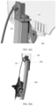
FIG. 1 is an example diagram of a conventional vehicle; -
FIG. 2 is an example diagram of a power supply apparatus according to an embodiment of this application; -
FIG. 3(a) is an example diagram of a partial structure of the power supply apparatus shown inFIG. 2 according to an embodiment of this application; -
FIG. 3(b) is an example diagram of a cross-section structure of a drag chain harness of the power supply apparatus shown inFIG. 2 according to an embodiment of this application; -
FIG. 4 is an example diagram of another power supply apparatus according to an embodiment of this application; -
FIG. 5 is an example diagram of still another power supply apparatus according to an embodiment of this application; -
FIG. 6 is an example diagram of yet another power supply apparatus according to an embodiment of this application; -
FIG. 7 is an example diagram of a position of a fastened end according to an embodiment of this application; and -
FIG. 8 is an example diagram of a vehicle door assembly according to an embodiment of this application. - The following describes technical solutions in embodiments in this application with reference to accompanying drawings.
- A power supply apparatus provided in the solutions of this application may be used in the fields such as transportation means, smart home, and construction. The transportation means may include one or more different types of transportation tools or movable objects that operate or move on land (for example, a highway, a road, or a railway), on water (for example, a waterway, a river, or an ocean), or in space. For example, the transportation means may include a vehicle (for example, a smart vehicle), a bicycle, a motorcycle, a train, a subway, an airplane, a ship, an aircraft, a robot, or another type of transportation tool or a movable object.
- A vehicle in the transportation means field is used as an example. The power supply apparatus provided in the solutions of this application may supply power to the vehicle door glass while providing a lifting function, so that the vehicle door glass can implement different functions such as light adjustment, color adjustment, display, and touch. The power supply apparatus provided in the solutions of this application may further supply power to a device such as a lidar and a sound system on the vehicle while providing a moving or lifting function, so that the lidar, the sound system, or the like can change a position according to a user requirement while working properly. The field of smart home is used as an example. The power supply apparatus provided in the solutions of this application may supply power to a display, a television, a curtain, or the like while providing a lifting or moving function, to implement different functions such as light adjustment, color adjustment, display, and touch for the display, the television, the curtain, or the like. The construction field is used as an example. The power supply apparatus provided in the solutions of this application may supply power to construction glass, a roof skylight, or the like while providing a lifting or moving function, to implement different functions such as light adjustment, color adjustment, display, and touch for the construction glass, the roof skylight, or the like.
- With reference to
FIG. 1 , the following briefly describes background technologies in embodiments of this application by using avehicle 100 as an example. -
FIG. 1 is an example diagram of a conventional vehicle. As shown inFIG. 1 , thevehicle 100 includes a vehicle door, and the vehicle door includesvehicle door glass 110 and a vehicle doorglass lifting apparatus 120. Thelifting apparatus 120 is usually disposed inside door sheet metal of the vehicle door. Optionally, in the vehicle field, thelifting apparatus 120 may also be referred to as a window lifter. This is not limited in this application. - As shown in
FIG. 1 , thelifting apparatus 120 may include: aclamp 121, aslider 122, aslide rail 123, apull cable 124, pulleys 125, and a motor andwinch 126. - The
clamp 121 may also be referred to as a fastening clip, and is configured to clamp and fasten thevehicle door glass 110. Optionally, in an actual structure, oneclamp 121 may be used, or two ormore clamps 121 may be used. This is not limited. - The
slider 122 is configured to connect to theclamp 121 and slide up and down inside theslide rail 123. As shown inFIG. 1 , a position of theslider 122A is a highest position to which the slider can slide, and a position of theslider 122B is a lowest position to which the slider can slide. - The
slide rail 123 may also be referred to as a track, and includes a slider groove. The slider groove is configured to restrict a sliding trajectory of theslider 122. Theslide rail 123 usually has a flange, and the flange may be coupled to theslider 122 to form a slidable system. Optionally, the slider groove may be formed through stamping or extrusion, and a cross section of the slider groove may be in a "U" shape, a "V" shape, a "C" shape, or the like, which is not limited. - The
pull cable 124 is connected to theslider 122, and theslider 122 is pulled to slide up and down inside theslide rail 123 through movement of thepull cable 124. - The pulleys 125 are configured to provide movement guidance and a proper turning radius for the
pull cable 124. Optionally, the pulleys 125 may includepulleys slide rail 123. - The motor and
winch 126 is configured to provide power for a lifting system and pull, through rotation of the winch, thepull cable 124 to move. - An overall working principle of the
lifting apparatus 120 is as follows: The motor drives the winch to rotate, the winch pulls thepull cable 124 to move, and thepull cable 124 forms a linear displacement inside theslide rail 123 by using thepulleys slider 122 to move up and down along theslide rail 123. Because theslider 122 is connected to thevehicle door glass 110 by using theclamp 121, theslider 122 may drive thevehicle door glass 110 to move up and down in a process in which theslider 122 moves up and down. - It can be learned that in a conventional vehicle, vehicle door glass is not powered. However, with the development of science and technology, a user has a higher requirement for vehicle door glass, and expects that the vehicle door glass can implement different functions such as privacy, sunshade, light adjustment, color adjustment, display, and touch. Power needs to be supplied to the vehicle door glass to implement the foregoing functions of the vehicle door glass. Therefore, how to supply power to the vehicle door glass is a technical problem that needs to be urgently resolved.
- Based on this, in embodiments of this application, on the basis of a conventional slide rail and a conventional slider, a drag chain harness and a drag chain harness groove used to accommodate the drag chain harness are added, a fastened end of the drag chain harness is electrically connected to a power supply, and a movable end is electrically connected to to-be-moved apparatuses such as vehicle door glass, so as to supply power to the to-be-moved apparatuses such as the vehicle door glass.
- The following describes the solutions of this application in detail with reference to
FIG. 2 to FIG. 7 . Structures shown inFIG. 2 to FIG. 7 are merely examples. Actually, more or fewer components may be included, and a shape and a structure of each component may be determined based on an actual situation. This is not limited in this application. -
FIG. 2 is an example diagram of a power supply apparatus according to an embodiment of this application. As shown inFIG. 2 , thepower supply apparatus 200 includes: aslide rail 210, aslider 220, a dragchain harness groove 230, and adrag chain harness 240. Theslider 220 is disposed on theslide rail 210, and theslider 220 may be configured to fasten a to-be-moved apparatus 201; the dragchain harness groove 230 is fastened to theslide rail 210; and thedrag chain harness 240 is disposed in the dragchain harness groove 230. Thedrag chain harness 240 includes a fastenedend 241 and amovable end 242. The fastenedend 241 is configured to electrically connect to a power supply, the fastenedend 241 is fastened relative to the dragchain harness groove 230, and themovable end 242 is configured to electrically connect to the to-be-moved apparatus 201. - The
slider 220 may move along a track direction of theslide rail 210. As shown inFIG. 2 , aslider 220A is a highest position to which theslider 220 can slide, and aslider 220B is a lowest position to which theslider 220 can slide. - Optionally, the
slider 220 may be used to fasten the to-be-moved apparatus 201 by using a fastening apparatus. For example, the fastening apparatus may be aclamp 250 shown inFIG. 2 . Specifically, theclamp 250 may be disposed on theslider 220, and then the to-be-moved apparatus 201 is clamped and fastened by using theclamp 250. Optionally, in an actual structure, oneclamp 121 may be used, or two ormore clamps 121 may be used. This is not limited in this application. - The
drag chain harness 240 includes a drag chain and a harness wrapped by the drag chain. The drag chain includes a plurality of chain sections, and the plurality of chain sections may be connected by using connecting pins. - Optionally, the to-
be-moved apparatus 201 may include to-be-moved glass, a display, a curtain, a television, a skylight, a lidar, a sound system, a camera, and the like that are used in the fields such as transportation means, smart home, construction, and smartphone. This is not limited in this application. The movement includes up-down movement, left-right movement, forward-backward movement, and the like. A movement direction of the to-be-moved apparatus 201 is not limited in this application. - According to the
power supply apparatus 200 provided in this embodiment of this application, the dragchain harness groove 230 and thedrag chain harness 240 are mainly added on the basis of theslide rail 210 and theslider 220. The dragchain harness groove 230 is fastened to theslide rail 210, thedrag chain harness 240 is disposed in the dragchain harness groove 230, and thedrag chain harness 240 includes the fastenedend 241 electrically connected to the power supply and themovable end 242 electrically connected to the to-be-moved apparatus 201, so that power can be supplied to the to-be-moved apparatus 201. - In addition, in this embodiment of this application, the
drag chain harness 240 is used, to protect and restrict an internal harness by using the drag chain, so as to avoid a problem of poor durability of the harness caused by direct use of the harness. In addition, thedrag chain harness 240 is disposed in the dragchain harness groove 230, so that a problem that the harness is wound and knotted can be avoided; and the dragchain harness groove 230 may provide guidance and limiting for thedrag chain harness 240, so as to prevent problems such as shaking and abnormal noise generated in a movement process of thedrag chain harness 240. - Optionally, the drag
chain harness groove 230 may be fastened on theslide rail 210 in a plurality of manners. - In an implementation, the drag
chain harness groove 230 may be directly disposed on theslide rail 210. Specifically, the dragchain harness groove 230 may be disposed on theslide rail 210 along the track direction of theslide rail 210, as shown inFIG. 2 andFIG. 4 . That the dragchain harness groove 230 is disposed on theslide rail 210 may be understood that the dragchain harness groove 230 and theslide rail 210 are integrally formed. - The drag
chain harness groove 230 in thepower supply apparatus 200 provided in this embodiment of this application may be disposed on theslide rail 210. In this way, integration of thepower supply apparatus 200 is higher, so that space is saved. In addition, it can be ensured that a track direction of the dragchain harness groove 230 is consistent with the track direction of theslide rail 210, so that consistency of movement trajectories of thedrag chain harness 240 and theslider 220 can be ensured. - In another implementation, the drag
chain harness groove 230 may be fastened to theslide rail 210 by using asupport 231, as shown inFIG. 5 . In this embodiment of this application, onesupport 231 may be used to fasten the dragchain harness groove 230 to theslide rail 210, or a plurality ofsupports 231 may be used to fasten the dragchain harness groove 230 to theslide rail 210. This is not limited. - In this embodiment of this application, the drag
chain harness groove 230 may be fastened on theslide rail 210 by using thesupport 231, which means that the dragchain harness groove 230 may be directly fastened on the basis of theconventional slide rail 210 by using thesupport 231, and theconventional slide rail 210 does not need to be improved, thereby reducing complexity of a manufacturing process. - In still another implementation, the drag
chain harness groove 230 may alternatively be fastened together with theslide rail 210 through bonding or welding. - Optionally, the
slide rail 210 may include aslider groove 211, theslider 220 is disposed in theslider groove 211 of theslide rail 210, and theslider groove 211 is configured to restrict a sliding trajectory of theslider 220. Theslide rail 210 usually has a flange, and the flange may be coupled to theslider 220 to form a slidable system. - Optionally, the
slider groove 211 may be formed through stamping, extrusion, or the like, and a cross section of theslider groove 211 may be in a "U" shape, a "V" shape, a "C" shape, or the like, which is not limited. Similarly, the dragchain harness groove 230 may also be formed through stamping, extrusion, or the like, and a cross section of the dragchain harness groove 230 may also be in a "U" shape, a "V" shape, a "C" shape, or the like, which is not limited. Cross sections of theslider groove 211 and the dragchain harness groove 230 may be the same, for example, both are in a "U" shape; or may be different, for example, one is in a "U" shape, and the other is in a "V" shape. This is not limited in this application. - In this embodiment of this application, position distributions of the drag
chain harness groove 230 and theslider groove 211 on a cross section are not limited, and may be flexibly set. Optionally, the dragchain harness groove 230 and theslider groove 211 may be distributed along a first direction; or the dragchain harness groove 230 and theslider groove 211 may be distributed along a second direction, where the first direction and the second direction may form a first included angle. - For example, the first direction may be perpendicular to the track direction of the
slide rail 210 and parallel to the plane on which the to-be-moved apparatus 201 is located, that is, an x direction shown inFIG. 2 ; the second direction may be perpendicular to the track direction of theslide rail 210 and perpendicular to the plane on which the to-be-moved apparatus 201 is located, that is, a y direction shown inFIG. 2 ; and the first included angle is 90°. - In this case, if the drag
chain harness groove 230 and theslider groove 211 are distributed along the first direction, openings of the dragchain harness groove 230 and theslider groove 211 may face the plane (as shown inFIG. 2 ,FIG. 5 , andFIG. 6 ) on which the to-be-moved apparatus 201 is located, so that consistency of movement trajectories of thedrag chain harness 240 and theslider 220 can be ensured. - If the drag
chain harness groove 230 and theslider groove 211 are distributed along the second direction, the opening of the dragchain harness groove 230 may face the plane on which the to-be-moved apparatus 201 is located, the dragchain harness groove 230 may be disposed on a side that is of theslider groove 211 and that is away from theslider groove 211, and the opening of the dragchain harness groove 230 faces the slider groove 211 (as shown inFIG. 4 ). In this way, integration of the power supply apparatus is higher, so that space is saved. In addition, it can be ensured that the track direction of the drag chain harness groove is consistent with the track direction of the slider groove, so that consistency of movement trajectories of the drag chain harness and the slider can be ensured. Optionally, in this case, the cross sections of the dragchain harness groove 230 and theslider groove 211 may be in a shape of an inverted "T" or in a variant form of the shape of the inverted "T". This is not limited. - Optionally, the
power supply apparatus 200 may further include alimiter 260. For thelimiter 260, refer toFIG. 2 to FIG. 6 . - Optionally, the
limiter 260 may be disposed on theslider 220, theclamp 250, the to-be-moved apparatus 201, or the like; and thelimiter 260 can move along with themovable end 242, and is configured to limit a projection of themovable end 242 on a cross section of thepower supply apparatus 200 to moving away from a projection of the fastenedend 241, so as to prevent a case such as shaking or abnormal noise generated by themovable end 242 of thedrag chain harness 240 in a moving process. - Optionally, a length of the
limiter 260 is not limited in this embodiment of this application. For example, the length of thelimiter 260 may be determined based on lengths of three to five sections of the drag chain. - Optionally, the
limiter 260 may include any one of a baffle plate, a stopper, a top reinforcement bar, and the like. This is not limited. - Location distributions of the fastened
end 241 and themovable end 242 on the cross section are not limited in this embodiment of this application, and may be flexibly set. Optionally, the fastenedend 241 and themovable end 242 may be distributed along a third direction; or the fastenedend 241 and themovable end 242 may be distributed along a fourth direction, where the third direction and the fourth direction may form a second included angle. - Optionally, the third direction may be perpendicular to the track direction of the
slide rail 210 and parallel to the plane on which the to-be-moved apparatus 201 is located (that is, the foregoing x direction). If the fastenedend 241 and themovable end 242 are distributed along this direction, a direction of a connecting pin of each section of the drag chain is perpendicular to the plane on which the to-be-moved apparatus 201 is located, which may also be understood as that a plane formed by the movement trajectory of the drag chain is parallel to the plane on which the to-be-moved apparatus 201 is located, as shown inFIG. 6 . In this case, the dragchain harness groove 230 occupies relatively small space, so that the integration of the power supply apparatus is higher and space is saved. - Optionally, the fourth direction may be perpendicular to the track direction of the
slide rail 210 and perpendicular to the plane on which the to-be-moved apparatus 201 is located (that is, the y direction). If the fastenedend 241 and themovable end 242 are distributed along this direction, a direction of a connecting pin of each section of the drag chain is parallel to the plane on which the to-be-moved apparatus 201 is located, which may also be understood as that a plane formed by a movement trajectory of the drag chain is perpendicular to the plane on which the to-be-moved apparatus 201 is located, as shown inFIG. 2 to FIG. 5 . In this case, the dragchain harness groove 230 occupies relatively small space, so that integration of the power supply apparatus is higher and space is saved. - Based on this, the second included angle may be 90°.
- In an actual operation, the third direction and the fourth direction may be respectively the x direction and the y direction, or may slightly deviate from the x direction and the y direction; and the second included angle may be 90°, or may be close to 90°. This is not limited in this application.
- In this embodiment of this application, the
movable end 242 may move together with the to-be-moved apparatus 201. - Optionally, that the
movable end 242 is configured to electrically connect to the to-be-moved apparatus 201 may be implemented in the following two implementations: - In an implementation, the
movable end 242 is electrically connected to the to-be-moved apparatus 201 indirectly by using an extended harness. For example, themovable end 242 may be fastened on a component that can be moved together with the to-be-moved apparatus 201, such as theslider 220 and theclamp 250, and then is electrically connected to the to-be-moved apparatus 201 by using the extended harness. In this implementation, because the component such as theslider 220 or theclamp 250 that can be moved together with the to-be-moved apparatus 201 is stationary relative to the to-be-moved apparatus 201, the extended harness is not dragged or pulled in a moving process, so that durability of the extended harness can be ensured. In addition, the harness in the movable end fastened to the component that can be moved together with the to-be-moved apparatus 201, such as theslider 220 or theclamp 250, is protected by the drag chain, so that the harness is not directly dragged or pulled in the moving process, thereby ensuring durability of the harness. - In another implementation, the
movable end 242 may be electrically connected to the to-be-moved apparatus 201 directly, that is, themovable end 242 is directly fastened on the to-be-moved apparatus 201. In this implementation, because the harness in themovable end 242 is protected by the drag chain, the harness is not directly dragged or pulled in the moving process, thereby ensuring durability of the harness. - Optionally, the
movable end 242 may be fastened to theslider 220, theclamp 250, the to-be-moved apparatus 201, or the like by using a conductive structure. The conductive structure may be a connector or another conductive connection structure. This is not limited. - Optionally, the fastened
end 241 may be electrically connected to the power supply directly, or may be electrically connected to the power supply by using a harness. This is not limited. - Optionally, the
power supply apparatus 200 may further include: apull cable 270, where thepull cable 270 is connected to theslider 220, and is configured to pull theslider 220 to move on theslide rail 210; pulleys 280, where the pulleys 280 includepulleys slide rail 210 and are configured to provide movement guidance and a turning radius for thepull cable 270; and a motor andwinch 290, where the motor andwinch 290 is configured to provide power to pull, through rotation of the winch, thepull cable 270 to move. - Optionally, the fastened
end 241 may be fastened at two ends of a movement stroke, or may be fastened between two ends of a movement stroke, for example, a midpoint or another position of the movement stroke.FIG. 7 is an example diagram of a position of a fastenedend 241 according to an embodiment of this application. (a) inFIG. 7 shows that the fastenedend 241 is fastened at a top of a movement stroke, and (b) inFIG. 7 shows that the fastenedend 241 is fastened between two ends of the movement stroke. As shown inFIG. 7 , when the fastenedend 241 is fastened between the two ends of the movement stroke, a length of thedrag chain harness 240 is significantly reduced, thereby reducing a weight and costs of thedrag chain harness 240. - For example, the fastened
end 241 may be fastened at two ends of the dragchain harness groove 230, or may be fastened at a first position between the two ends of the dragchain harness groove 230. When the fastenedend 241 is fastened between two ends of the dragchain harness groove 230, compared with a case in which the fastenedend 241 is fastened to the two ends of the dragchain harness groove 230, a length of thedrag chain harness 240 can be reduced, and a weight and costs of thedrag chain harness 240 can be reduced. - For example, if the foregoing motor is disposed between the two ends of the
slide rail 210, the fastenedend 241 may be further fastened to the motor. In this case, the fastenedend 241 may be fastened on the motor. Compared with the case in which the fastenedend 241 is fastened to the two ends of the dragchain harness groove 230, a length of thedrag chain harness 240 can be reduced, and a weight and costs of thedrag chain harness 240 can be reduced. - The foregoing position of the fastened
end 242 is merely an example. In an actual operation, a specific position at which the fastenedend 242 is fastened is determined based on an actual situation. This is not limited in this application, provided that the fastenedend 242 is stationary relative to the dragchain harness groove 230. - An overall working principle of the
power supply apparatus 200 is as follows: The motor drives the winch to rotate, the winch pulls thepull cable 270 to move, and thepull cable 270 forms a linear displacement inside theslide rail 210 by using thepulleys slider 220 to move up and down along theslide rail 210. Because theslider 220 is connected to the to-be-moved apparatus 201 by using theclamp 250, theslider 220 can drive the to-be-moved apparatus 201 to move up and down. Similarly, thedrag chain harness 240 may transfer power of the power supply to the to-be-moved apparatus 201, so as to supply power to the to-be-moved apparatus 201. - Optionally, in this embodiment of this application, a communication harness may be further introduced into the drag chain harness, to implement communication between the to-
be-moved apparatus 201 and another device. -
FIG. 8 is an example diagram of a vehicle door assembly according to an embodiment of this application. As shown inFIG. 8 , thevehicle door assembly 800 includesvehicle door glass 810 and apower supply apparatus 820. Thepower supply apparatus 820 is disposed inside the door sheet metal of a vehicle door, and thepower supply apparatus 820 is configured to supply power to thevehicle door glass 810 while providing a moving function for thevehicle door glass 810. - The
power supply apparatus 820 includes: a slide rail; a slider, where the slider is disposed on the slide rail, and the slider is configured to fasten thevehicle door glass 810; a drag chain harness groove, where the drag chain harness groove is disposed parallel to the slide rail; and a drag chain harness, where the drag chain harness is disposed in the drag chain harness groove, the drag chain harness includes a fastened end and a movable end, the fastened end is configured to electrically connect to a power supply, the fastened end is fastened relative to the drag chain harness groove, and the movable end is configured to electrically connect to thevehicle door glass 810. - The
vehicle door assembly 800 provided in this embodiment of this application mainly includes thevehicle door glass 810 and thepower supply apparatus 820. Thepower supply apparatus 820 includes the slide rail, the slider, the drag chain harness groove, and the drag chain harness. The drag chain harness includes the fastened end configured to electrically connect to the power supply and the movable end configured to electrically connect to thevehicle door glass 810, so that thevehicle door glass 810 can be powered while a moving function is provided for thevehicle door glass 810. - In addition, in this embodiment of this application, the drag chain harness is used, to protect and restrict an internal harness by using the drag chain, so as to avoid a problem of poor durability of the harness caused by direct use of the harness. In addition, the drag chain harness is disposed in the drag chain harness groove, so that a problem that the harness is wound and knotted can be avoided; and the drag chain harness groove may provide guidance and limiting for the drag chain harness, so as to prevent problems such as shaking and abnormal noise generated in a movement process of the drag chain harness.
- In an implementation, the drag chain harness groove may be fastened to the vehicle door.
- Optionally, the drag chain harness groove may be integrated with the vehicle door, or may be fastened to the vehicle door by using a support or another connecting piece, or may be fastened to the vehicle door through bonding, welding, or the like. This is not limited in this application.
- In another implementation, the drag chain harness groove may be fastened to the slide rail.
- Optionally, the drag chain harness groove may be integrated with the slide rail, or may be fastened to the slide rail by using a support or another connecting piece, or may be fastened to the slide rail through bonding, welding, or the like. This is not limited in this application.
- For other content related to the
vehicle door assembly 800, refer to the foregoing descriptions. Details are not described herein again. - An embodiment of this application further provides a vehicle, including the foregoing
power supply apparatus 200 or the foregoingvehicle door assembly 800. - An embodiment of this application further provides an electronic device, including the foregoing
power supply apparatus 200. Optionally, the electronic device includes a smart home device, a construction device, a vehicle, a smartphone, and the like. This is not limited in this application. - The foregoing descriptions are merely specific implementations of this application, but the protection scope of this application is not limited thereto. Any variation or replacement readily figured out by a person skilled in the art within the technical scope disclosed in this application shall fall within the protection scope of this application. Therefore, the protection scope of this application shall be subject to the protection scope of the claims.
Claims (17)
- A power supply apparatus, comprising:a slide rail;a slider, wherein the slider is disposed on the slide rail, and the slider is configured to fasten a to-be-moved apparatus;a drag chain harness groove, wherein the drag chain harness groove is fastened to the slide rail; anda drag chain harness, wherein the drag chain harness is disposed in the drag chain harness groove, whereinthe drag chain harness comprises a fastened end and a movable end, the fastened end is configured to electrically connect to a power supply, the fastened end is fastened relative to the drag chain harness groove, and the movable end is configured to electrically connect to the to-be-moved apparatus.
- The power supply apparatus according to claim 1, wherein the slide rail comprises a slider groove, the slider is disposed in the slider groove of the slide rail, and the drag chain harness groove and the slider groove are distributed along a first direction; or the drag chain harness groove and the slider groove are distributed along a second direction, wherein the first direction and the second direction form a first included angle.
- The power supply apparatus according to claim 2, wherein the first direction is perpendicular to a track direction of the slide rail, and the first direction is parallel to a plane on which the to-be-moved apparatus is located; and if the drag chain harness groove and the slider groove are distributed along the first direction, openings of the drag chain harness groove and the slider groove face the plane on which the to-be-moved apparatus is located.
- The power supply apparatus according to claim 2, wherein the second direction is perpendicular to a track direction of the slide rail, and the second direction is perpendicular to a plane on which the to-be-moved apparatus is located; and if the drag chain harness groove and the slider groove are distributed along the second direction, an opening of the drag chain harness groove faces the plane on which the to-be-moved apparatus is located, the drag chain harness groove is disposed on a side that is of the slider groove and that is away from the slider groove, and the opening of the drag chain harness groove faces the slider groove.
- The power supply apparatus according to any one of claims 1 to 4, wherein the drag chain harness groove is disposed on the slide rail.
- The power supply apparatus according to any one of claims 1 to 3, wherein the drag chain harness groove is fastened to the slide rail by using a support.
- The power supply apparatus according to any one of claims 1 to 6, wherein the power supply apparatus further comprises:
a limiter, wherein the limiter is disposed on the slider or the to-be-moved apparatus, and is configured to limit a projection of the movable end on a cross section of the power supply apparatus to moving away from a projection of the fastened end. - The power supply apparatus according to any one of claims 1 to 7, wherein the fastened end and the movable end are distributed along a third direction; or the fastened end and the movable end are distributed along a fourth direction, wherein the third direction and the fourth direction form a second included angle.
- The power supply apparatus according to any one of claims 1 to 8, wherein the fastened end is fastened at a first position on the drag chain harness groove, and the first position is located between two ends of the drag chain harness groove.
- The power supply apparatus according to any one of claims 1 to 9, wherein the power supply apparatus further comprises:a pull cable, wherein the pull cable is connected to the slider and is configured to pull the slider to move on the slide rail;pulleys, wherein the pulleys are disposed at two ends of the slide rail and are configured to provide movement guidance and a turning radius for the pull cable; anda motor and winch, wherein the motor and winch is configured to provide power to pull, through rotation of the winch, the pull cable to move.
- The power supply apparatus according to claim 10, wherein the motor is disposed between the two ends of the slide rail, and the fastened end is fastened to the motor.
- The power supply apparatus according to any one of claims 1 to 11, wherein the movable end is fastened to the slider, and the movable end is electrically connected to the to-be-moved apparatus by using an extended harness; or the movable end is fastened to the to-be-moved apparatus.
- A vehicle door assembly, comprising: vehicle door glass and a power supply apparatus, wherein the power supply apparatus comprises:a slide rail;a slider, wherein the slider is disposed on the slide rail, and the slider is configured to fasten the vehicle door glass;a drag chain harness groove, wherein the drag chain harness groove is disposed parallel to the slide rail; anda drag chain harness, wherein the drag chain harness is disposed in the drag chain harness groove, whereinthe drag chain harness comprises a fastened end and a movable end, the fastened end is configured to electrically connect to a power supply, the fastened end is fastened relative to the drag chain harness groove, and the movable end is configured to electrically connect to the vehicle door glass.
- The vehicle door assembly according to claim 13, wherein the drag chain harness groove is fastened to a vehicle door.
- The vehicle door assembly according to claim 13, wherein the drag chain harness groove is fastened to the slide rail.
- A vehicle, comprising the power supply apparatus according to any one of claims 1 to 12.
- An electronic device, comprising the power supply apparatus according to any one of claims 1 to 12.
Applications Claiming Priority (1)
| Application Number | Priority Date | Filing Date | Title |
|---|---|---|---|
| PCT/CN2022/102884 WO2024000426A1 (en) | 2022-06-30 | 2022-06-30 | Power supply apparatus, door assembly, vehicle and electronic device |
Publications (2)
| Publication Number | Publication Date |
|---|---|
| EP4538118A1 true EP4538118A1 (en) | 2025-04-16 |
| EP4538118A4 EP4538118A4 (en) | 2025-08-20 |
Family
ID=89383766
Family Applications (1)
| Application Number | Title | Priority Date | Filing Date |
|---|---|---|---|
| EP22948531.3A Pending EP4538118A4 (en) | 2022-06-30 | 2022-06-30 | POWER SUPPLY DEVICE, DOOR ARRANGEMENT, VEHICLE AND ELECTRONIC DEVICE |
Country Status (4)
| Country | Link |
|---|---|
| US (1) | US20250129655A1 (en) |
| EP (1) | EP4538118A4 (en) |
| CN (1) | CN119343271A (en) |
| WO (1) | WO2024000426A1 (en) |
Family Cites Families (26)
| Publication number | Priority date | Publication date | Assignee | Title |
|---|---|---|---|---|
| JP2000247192A (en) * | 1999-02-24 | 2000-09-12 | Sumitomo Wiring Syst Ltd | Wire harness arrangement structure to glass hutch in back door of motor vehicle |
| JP4516232B2 (en) * | 2000-04-11 | 2010-08-04 | 矢崎総業株式会社 | Power supply structure for slide structure |
| US6766617B2 (en) * | 2002-08-12 | 2004-07-27 | Dura Global Technologies, Inc. | Power sliding rear window |
| US7213370B2 (en) * | 2004-09-01 | 2007-05-08 | Dura Global Technologies, Inc. | Window regulator |
| US20060059782A1 (en) * | 2004-09-20 | 2006-03-23 | Hi-Lex Corporation | Cord support for window regulator |
| US20080005971A1 (en) * | 2006-06-21 | 2008-01-10 | Dickie Robert Boyer | Single Rail No Pulley Window Regulator |
| JP4727547B2 (en) * | 2006-10-11 | 2011-07-20 | 三井金属アクト株式会社 | Vehicle window regulator device |
| US8402695B2 (en) * | 2009-08-06 | 2013-03-26 | Magna Mirrors Of America, Inc. | Heated rear slider window assembly |
| EP2616259B1 (en) * | 2010-09-15 | 2019-04-10 | Magna Mirrors Of America, Inc. | Slider window assembly |
| US8938914B2 (en) * | 2010-10-01 | 2015-01-27 | Magna Mirrors Of America, Inc. | Slider window assembly with cable guides |
| CN203223089U (en) * | 2013-03-18 | 2013-10-02 | 宁波世通汽车零部件有限公司 | Vehicle window electric glass lifter |
| DE102014104418A1 (en) * | 2014-03-28 | 2015-10-01 | Küster Holding GmbH | Electrically switchable motor vehicle glazing |
| US9579955B2 (en) * | 2014-08-26 | 2017-02-28 | Magna Mirros Of America, Inc. | Rear slider window assembly with heated movable window |
| DE102015214377A1 (en) * | 2015-07-29 | 2017-02-02 | Brose Fahrzeugteile Gmbh & Co. Kommanditgesellschaft, Bamberg | Device for fastening and electrical contacting of a vehicle window pane |
| US9771746B2 (en) * | 2015-07-30 | 2017-09-26 | GM Global Technology Operations LLC | Window regulator for a door assembly of a vehicle |
| FR3041676B1 (en) * | 2015-09-24 | 2019-07-19 | Inteva Products France Sas | Apparatus and method for a pulley reinforcement in a window lift |
| US9920560B2 (en) * | 2016-03-21 | 2018-03-20 | Dura Operating, Llc | Window assembly with a movable pane and a defrost assembly |
| JP6457992B2 (en) * | 2016-11-22 | 2019-01-23 | 矢崎総業株式会社 | Bending restriction member and power feeding device |
| CN109130967B (en) * | 2018-08-29 | 2020-02-07 | 延锋安道拓座椅有限公司 | Improved generation car seat electric ground slide rail system |
| CN209037518U (en) * | 2018-10-30 | 2019-06-28 | 延锋安道拓座椅有限公司 | A kind of automotive seat drag chain type power supply unit |
| US11318818B2 (en) * | 2019-02-15 | 2022-05-03 | Hi-Lex Controls, Inc. | Window regulator with power supply connection for electrical device on movable glass |
| DE102020205551A1 (en) * | 2020-02-10 | 2021-08-12 | Brose Fahrzeugteile Se & Co. Kommanditgesellschaft, Bamberg | Assembly of an adjusting device of a motor vehicle |
| CN212313336U (en) * | 2020-08-18 | 2021-01-08 | 重庆延锋安道拓汽车部件系统有限公司 | Car seat slide rail assembly capable of concealed installation |
| KR102522129B1 (en) * | 2021-02-17 | 2023-04-17 | (주)광진기계 | Power supply apparatus for windows of vehicle |
| DE102021202669B3 (en) * | 2021-03-18 | 2022-05-25 | Brose Fahrzeugteile Se & Co. Kommanditgesellschaft, Bamberg | Assembly of an adjustment device and window lifter for a motor vehicle |
| CN216331341U (en) * | 2021-10-18 | 2022-04-19 | 长城汽车股份有限公司 | Glass assembly of vehicle and vehicle that has it |
-
2022
- 2022-06-30 EP EP22948531.3A patent/EP4538118A4/en active Pending
- 2022-06-30 CN CN202280096938.0A patent/CN119343271A/en active Pending
- 2022-06-30 WO PCT/CN2022/102884 patent/WO2024000426A1/en not_active Ceased
-
2024
- 2024-12-30 US US19/005,008 patent/US20250129655A1/en active Pending
Also Published As
| Publication number | Publication date |
|---|---|
| US20250129655A1 (en) | 2025-04-24 |
| EP4538118A4 (en) | 2025-08-20 |
| JP2025526273A (en) | 2025-08-13 |
| WO2024000426A1 (en) | 2024-01-04 |
| CN119343271A (en) | 2025-01-21 |
Similar Documents
| Publication | Publication Date | Title |
|---|---|---|
| EP3599312B1 (en) | Work vehicle with a variably positionable camera and related systems | |
| US20250129655A1 (en) | Power Supply Apparatus, Vehicle Door Assembly, Vehicle, and Electronic Device | |
| CN207559461U (en) | A kind of fastener for positioning wires | |
| JP7862668B2 (en) | Power supplies, vehicle door assemblies, vehicles, and electronic devices | |
| CN114524034B (en) | Light-weight guy rope type control device of ground unmanned system | |
| CN209321091U (en) | A kind of tunnel obstacle removing robot | |
| CN209644614U (en) | A kind of intelligent electric Rome bar | |
| EP1091074A2 (en) | Window systems for automotive vehicle | |
| CN219029313U (en) | Camera device and vehicle | |
| CN207906746U (en) | Security system monitoring device mounting seat | |
| CN211195804U (en) | Skylight sunshade cord fabric guide structure | |
| TWI243148B (en) | Elevator with duct for tail cord | |
| CN223085921U (en) | Fire engine carries unmanned aerial vehicle lift platform and fire engine | |
| CN213322948U (en) | Lens set capable of guiding cable | |
| CN219947874U (en) | Vehicle door components and vehicles including the door components | |
| CN213063283U (en) | Track section bar and electrically operated gate device | |
| CN224207171U (en) | Support arm structure | |
| CN213905516U (en) | An adjustable installation structure power battery pack | |
| CN221377006U (en) | Adjustment mechanism and detection system of vehicle-mounted display screen | |
| CN218579484U (en) | Visual monitoring device for tower crane hook | |
| CN117477198B (en) | coupler | |
| CN209556729U (en) | A car window lift controller shell | |
| CN218819256U (en) | Infrared camera with wide monitoring range | |
| CN220809336U (en) | Wire harness fixing device and vehicle | |
| CN216916331U (en) | Remote sensing telemetering measurement unmanned aerial vehicle retrieves platform |
Legal Events
| Date | Code | Title | Description |
|---|---|---|---|
| STAA | Information on the status of an ep patent application or granted ep patent |
Free format text: STATUS: THE INTERNATIONAL PUBLICATION HAS BEEN MADE |
|
| PUAI | Public reference made under article 153(3) epc to a published international application that has entered the european phase |
Free format text: ORIGINAL CODE: 0009012 |
|
| STAA | Information on the status of an ep patent application or granted ep patent |
Free format text: STATUS: REQUEST FOR EXAMINATION WAS MADE |
|
| 17P | Request for examination filed |
Effective date: 20250108 |
|
| AK | Designated contracting states |
Kind code of ref document: A1 Designated state(s): AL AT BE BG CH CY CZ DE DK EE ES FI FR GB GR HR HU IE IS IT LI LT LU LV MC MK MT NL NO PL PT RO RS SE SI SK SM TR |
|
| A4 | Supplementary search report drawn up and despatched |
Effective date: 20250718 |
|
| RIC1 | Information provided on ipc code assigned before grant |
Ipc: B60R 16/02 20060101AFI20250714BHEP Ipc: B60J 1/00 20060101ALI20250714BHEP Ipc: E05F 11/48 20060101ALI20250714BHEP Ipc: E05F 15/689 20150101ALI20250714BHEP Ipc: H02G 11/00 20060101ALI20250714BHEP |
|
| DAV | Request for validation of the european patent (deleted) | ||
| DAX | Request for extension of the european patent (deleted) |