EP4537726A1 - Klippensensor und selbstbewegende vorrichtung - Google Patents
Klippensensor und selbstbewegende vorrichtung Download PDFInfo
- Publication number
- EP4537726A1 EP4537726A1 EP22945594.4A EP22945594A EP4537726A1 EP 4537726 A1 EP4537726 A1 EP 4537726A1 EP 22945594 A EP22945594 A EP 22945594A EP 4537726 A1 EP4537726 A1 EP 4537726A1
- Authority
- EP
- European Patent Office
- Prior art keywords
- light
- convex lens
- shell
- cliff sensor
- partition
- Prior art date
- Legal status (The legal status is an assumption and is not a legal conclusion. Google has not performed a legal analysis and makes no representation as to the accuracy of the status listed.)
- Pending
Links
Images


Classifications
-
- A—HUMAN NECESSITIES
- A47—FURNITURE; DOMESTIC ARTICLES OR APPLIANCES; COFFEE MILLS; SPICE MILLS; SUCTION CLEANERS IN GENERAL
- A47L—DOMESTIC WASHING OR CLEANING; SUCTION CLEANERS IN GENERAL
- A47L9/00—Details or accessories of suction cleaners, e.g. mechanical means for controlling the suction or for effecting pulsating action; Storing devices specially adapted to suction cleaners or parts thereof; Carrying-vehicles specially adapted for suction cleaners
- A47L9/28—Installation of the electric equipment, e.g. adaptation or attachment to the suction cleaner; Controlling suction cleaners by electric means
- A47L9/2805—Parameters or conditions being sensed
- A47L9/2826—Parameters or conditions being sensed the condition of the floor
-
- A—HUMAN NECESSITIES
- A47—FURNITURE; DOMESTIC ARTICLES OR APPLIANCES; COFFEE MILLS; SPICE MILLS; SUCTION CLEANERS IN GENERAL
- A47L—DOMESTIC WASHING OR CLEANING; SUCTION CLEANERS IN GENERAL
- A47L11/00—Machines for cleaning floors, carpets, furniture, walls, or wall coverings
- A47L11/28—Floor-scrubbing machines, motor-driven
-
- A—HUMAN NECESSITIES
- A47—FURNITURE; DOMESTIC ARTICLES OR APPLIANCES; COFFEE MILLS; SPICE MILLS; SUCTION CLEANERS IN GENERAL
- A47L—DOMESTIC WASHING OR CLEANING; SUCTION CLEANERS IN GENERAL
- A47L11/00—Machines for cleaning floors, carpets, furniture, walls, or wall coverings
- A47L11/40—Parts or details of machines not provided for in groups A47L11/02 - A47L11/38, or not restricted to one of these groups, e.g. handles, arrangements of switches, skirts, buffers, levers
- A47L11/4061—Steering means; Means for avoiding obstacles; Details related to the place where the driver is accommodated
-
- A—HUMAN NECESSITIES
- A47—FURNITURE; DOMESTIC ARTICLES OR APPLIANCES; COFFEE MILLS; SPICE MILLS; SUCTION CLEANERS IN GENERAL
- A47L—DOMESTIC WASHING OR CLEANING; SUCTION CLEANERS IN GENERAL
- A47L11/00—Machines for cleaning floors, carpets, furniture, walls, or wall coverings
- A47L11/40—Parts or details of machines not provided for in groups A47L11/02 - A47L11/38, or not restricted to one of these groups, e.g. handles, arrangements of switches, skirts, buffers, levers
- A47L11/4002—Installations of electric equipment
-
- A—HUMAN NECESSITIES
- A47—FURNITURE; DOMESTIC ARTICLES OR APPLIANCES; COFFEE MILLS; SPICE MILLS; SUCTION CLEANERS IN GENERAL
- A47L—DOMESTIC WASHING OR CLEANING; SUCTION CLEANERS IN GENERAL
- A47L11/00—Machines for cleaning floors, carpets, furniture, walls, or wall coverings
- A47L11/40—Parts or details of machines not provided for in groups A47L11/02 - A47L11/38, or not restricted to one of these groups, e.g. handles, arrangements of switches, skirts, buffers, levers
- A47L11/4011—Regulation of the cleaning machine by electric means; Control systems and remote control systems therefor
-
- A—HUMAN NECESSITIES
- A47—FURNITURE; DOMESTIC ARTICLES OR APPLIANCES; COFFEE MILLS; SPICE MILLS; SUCTION CLEANERS IN GENERAL
- A47L—DOMESTIC WASHING OR CLEANING; SUCTION CLEANERS IN GENERAL
- A47L11/00—Machines for cleaning floors, carpets, furniture, walls, or wall coverings
- A47L11/40—Parts or details of machines not provided for in groups A47L11/02 - A47L11/38, or not restricted to one of these groups, e.g. handles, arrangements of switches, skirts, buffers, levers
- A47L11/4036—Parts or details of the surface treating tools
-
- A—HUMAN NECESSITIES
- A47—FURNITURE; DOMESTIC ARTICLES OR APPLIANCES; COFFEE MILLS; SPICE MILLS; SUCTION CLEANERS IN GENERAL
- A47L—DOMESTIC WASHING OR CLEANING; SUCTION CLEANERS IN GENERAL
- A47L11/00—Machines for cleaning floors, carpets, furniture, walls, or wall coverings
- A47L11/40—Parts or details of machines not provided for in groups A47L11/02 - A47L11/38, or not restricted to one of these groups, e.g. handles, arrangements of switches, skirts, buffers, levers
- A47L11/408—Means for supplying cleaning or surface treating agents
- A47L11/4083—Liquid supply reservoirs; Preparation of the agents, e.g. mixing devices
-
- A—HUMAN NECESSITIES
- A47—FURNITURE; DOMESTIC ARTICLES OR APPLIANCES; COFFEE MILLS; SPICE MILLS; SUCTION CLEANERS IN GENERAL
- A47L—DOMESTIC WASHING OR CLEANING; SUCTION CLEANERS IN GENERAL
- A47L11/00—Machines for cleaning floors, carpets, furniture, walls, or wall coverings
- A47L11/40—Parts or details of machines not provided for in groups A47L11/02 - A47L11/38, or not restricted to one of these groups, e.g. handles, arrangements of switches, skirts, buffers, levers
- A47L11/408—Means for supplying cleaning or surface treating agents
- A47L11/4088—Supply pumps; Spraying devices; Supply conduits
-
- A—HUMAN NECESSITIES
- A47—FURNITURE; DOMESTIC ARTICLES OR APPLIANCES; COFFEE MILLS; SPICE MILLS; SUCTION CLEANERS IN GENERAL
- A47L—DOMESTIC WASHING OR CLEANING; SUCTION CLEANERS IN GENERAL
- A47L9/00—Details or accessories of suction cleaners, e.g. mechanical means for controlling the suction or for effecting pulsating action; Storing devices specially adapted to suction cleaners or parts thereof; Carrying-vehicles specially adapted for suction cleaners
- A47L9/28—Installation of the electric equipment, e.g. adaptation or attachment to the suction cleaner; Controlling suction cleaners by electric means
- A47L9/2836—Installation of the electric equipment, e.g. adaptation or attachment to the suction cleaner; Controlling suction cleaners by electric means characterised by the parts which are controlled
- A47L9/2852—Elements for displacement of the vacuum cleaner or the accessories therefor, e.g. wheels, casters or nozzles
-
- B—PERFORMING OPERATIONS; TRANSPORTING
- B25—HAND TOOLS; PORTABLE POWER-DRIVEN TOOLS; MANIPULATORS
- B25J—MANIPULATORS; CHAMBERS PROVIDED WITH MANIPULATION DEVICES
- B25J19/00—Accessories fitted to manipulators, e.g. for monitoring, for viewing; Safety devices combined with or specially adapted for use in connection with manipulators
- B25J19/02—Sensing devices
- B25J19/021—Optical sensing devices
- B25J19/022—Optical sensing devices using lasers
-
- G—PHYSICS
- G01—MEASURING; TESTING
- G01S—RADIO DIRECTION-FINDING; RADIO NAVIGATION; DETERMINING DISTANCE OR VELOCITY BY USE OF RADIO WAVES; LOCATING OR PRESENCE-DETECTING BY USE OF THE REFLECTION OR RERADIATION OF RADIO WAVES; ANALOGOUS ARRANGEMENTS USING OTHER WAVES
- G01S7/00—Details of systems according to groups G01S13/00, G01S15/00, G01S17/00
- G01S7/48—Details of systems according to groups G01S13/00, G01S15/00, G01S17/00 of systems according to group G01S17/00
- G01S7/481—Constructional features, e.g. arrangements of optical elements
- G01S7/4811—Constructional features, e.g. arrangements of optical elements common to transmitter and receiver
-
- A—HUMAN NECESSITIES
- A47—FURNITURE; DOMESTIC ARTICLES OR APPLIANCES; COFFEE MILLS; SPICE MILLS; SUCTION CLEANERS IN GENERAL
- A47L—DOMESTIC WASHING OR CLEANING; SUCTION CLEANERS IN GENERAL
- A47L2201/00—Robotic cleaning machines, i.e. with automatic control of the travelling movement or the cleaning operation
- A47L2201/04—Automatic control of the travelling movement; Automatic obstacle detection
-
- G—PHYSICS
- G01—MEASURING; TESTING
- G01S—RADIO DIRECTION-FINDING; RADIO NAVIGATION; DETERMINING DISTANCE OR VELOCITY BY USE OF RADIO WAVES; LOCATING OR PRESENCE-DETECTING BY USE OF THE REFLECTION OR RERADIATION OF RADIO WAVES; ANALOGOUS ARRANGEMENTS USING OTHER WAVES
- G01S17/00—Systems using the reflection or reradiation of electromagnetic waves other than radio waves, e.g. lidar systems
- G01S17/88—Lidar systems specially adapted for specific applications
- G01S17/93—Lidar systems specially adapted for specific applications for anti-collision purposes
Definitions
- the present disclosure relates to the field of sensors, and in particular to a cliff sensor and a self-moving device.
- a self-moving device is a machine that moves autonomously and works automatically. In its working environment, the self-moving device often encounters cliffs (such as stairs and thresholds). When the self-moving device encounters a cliff, it may fall off, in which case the self-moving device is prone to getting damaged.
- cliffs such as stairs and thresholds
- an embodiment of the present disclosure provides a cliff sensor, including a light emitter and a light receiver, wherein
- a second total reflection structure is provided on a portion of the second convex lens close to the partition, and the second total reflection structure is configured to totally reflect second light such that the second light is received by the light receiver, the second light being part of light that is emergent from the first convex lens, reflected by a surface to be operated into the second convex lens and directed to the partition.
- the first total reflection structure includes a first inclined surface, which is located in a region of the first convex lens close to the partition, the first inclined surface gradually inclines away from the partition from a first end to a second end, the first end is an end of the first inclined surface away from the light emitter, and the second end is an end of the first inclined surface close to the light emitter.
- the second total reflection structure includes a second inclined surface, which is located in a region on an emergent surface of the second convex lens close to the partition, the second inclined surface gradually inclines away from the partition from a third end to a fourth end, the third end is an end of the second inclined surface away from the light receiver, and the fourth end is an end of the second inclined surface close to the light receiver.
- the cliff sensor includes a housing, an accommodating chamber is provided in the housing, and the light emitter, the light receiver and the partition are all arranged in the accommodating chamber; and the first convex lens and the second convex lens are mounted on a bearing wall surface of the housing, and the bearing wall surface is a light-transmitting wall surface, wherein the bearing wall surface is a wall surface of the housing which directly faces emitted light of the light emitter and through which incident light of the light receiver passes.
- an incident surface of the first convex lens protrudes toward a direction close to the light emitter, and an emergent surface of the first convex lens is a plane; and the emergent surface of the second convex lens protrudes toward a direction of the light receiver, and an incident surface of the second convex lens is a plane.
- a first opening is further provided on the housing at a position corresponding to a plug-in end of the connector, the connector is located at the first opening, and an outer edge of the connector is flush with an edge of the first opening.
- the connector is provided with a connecting wire
- a second opening is provided on the housing at a position corresponding to a connection between the connector and the connecting wire
- the connecting wire passes through the second opening
- a blocking member is provided at the second opening to seal the second opening.
- the housing includes a first shell and a second shell connected to the first shell, such that the accommodating chamber includes a first chamber arranged in the first shell and a second chamber arranged in the second shell, the first convex lens, the second convex lens, the partition, the light receiver and the light emitter are located in the first chamber, and the connector is located in the second chamber.
- first shell and the second shell are connected in a fixed or detachable manner.
- the second shell includes a first sub-shell and a second sub-shell, and the first sub-shell and the second sub-shell are snap-fitted to form the second chamber.
- the blocking member is made of soft rubber material.
- an existing moving device may be provided with a cliff sensor to identify the cliff.
- the self-moving device stops advancing or takes an evasive action, thereby effectively preventing the self-moving device from being damaged due to falling off from a height.
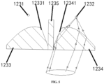
- a first total reflection structure is provided on a portion of the first convex lens 1233 close to the partition 1235, and the first total reflection structure is configured to totally reflect first light such that the first light is emergent from the first convex lens 1233 in a direction approximately parallel to a preset direction.
- the first light is part of light emitted by the light emitter 1231 and directed to the partition 1235 in the first convex lens 1233, and the preset direction is a direction of a path of light emitted by the light emitter 1231 and converted into approximately parallel light via the first convex lens 1233.
- the light receiver 1232 and the light emitter 1231 are generally infrared sensors, or laser radars.
- the partition 1235 may be in the shape of a plate or other irregular shapes.
- the partition 1235 is made of an opaque material, thereby preventing the light emitted by the light emitter 1231 from being directly received by the receiver 40 without being reflected by a surface of a region to be operated.
- the light emitted by the light emitter 1231 is directed into the first convex lens 1233.
- Most of the light that is not directed to the partition 1235 is converted into approximately parallel light via the first convex lens 1233 and then emergent.
- Part of the light directed to the partition 1235, i.e., first light is totally reflected by the first total reflection structure, such that the first light is emergent in a direction approximately parallel to a preset direction.
- part of the light directed to the partition 1235 in the first convex lens 1233 is totally reflected by means of the first total reflection structure of the first convex lens 1233, such that the part of the light directed to the partition 1235 in the first convex lens 1233 is converted into approximately parallel light and then emergent.
- the intensity of the light reflected by the surface to be operated and received by the light receiver 1232 is increased, the misjudgment rate of the cliff sensor is reduced, and the sensing accuracy of the cliff sensor is improved.
- the light receiver 1232 may also receive a relatively strong light signal, such that the influence of color on the cliff sensor is also reduced.
- the first total reflection structure includes a first inclined surface 12331, which is located in a region of the first convex lens 1233 close to the partition 1235.
- the first inclined surface 12331 gradually inclines away from the partition 1235 from a first end to a second end.
- the first end is an end of the first inclined surface 12331 away from the light emitter 1231.
- the second end is an end of the first inclined surface 12331 close to the light emitter 1231.
- the first inclined surface 12331 gradually inclines from the first end to the second end in a direction away from the partition 1235, such that the distance between the first inclined surface 12331 and the partition 1235 gradually increases from the first end to the second end. That is, the gap between the first inclined surface 12331 and the partition 1235 gradually increases from the first end to the second end, such that a medium on one side of the first inclined surface 12331 is the material i.e., an optically denser medium, of the first convex lens 1233, and a medium on the other side is air, i.e., an optically rarer medium. In this way, the first inclined surface 12331 becomes a total reflection surface, which enables total reflection of the first light.
- part of the light emergent from the first convex lens 1233 and reflected by the surface to be operated into the second convex lens 1234 is directed to a joint interface between the second convex lens 1234 and the partition 1235. These light rays are reflected by the joint interface and change their original light paths. In this way, these light rays cannot be received by the light receiver 1232 after being emergent from the second convex lens 1234, such that the intensity of the light received by the light receiver 1232 is reduced to a certain extent.
- the second light is totally reflected by means of the second total reflection structure of the second convex lens 1234, such that after the second light is emergent from the second convex lens 1234, it can still be received by the light receiver 1232, such that the intensity of the light received by the light receiver 1232 is improved.
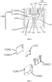
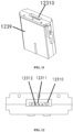
- the cliff sensor includes a housing 1239.
- An accommodating chamber 1236 is provided in the housing 1239, and the light emitter 1231, the light receiver 1232 and the partition 1235 are all arranged in the accommodating chamber 1236.
- the first convex lens 1233 and the second convex lens 1234 are mounted on a bearing wall surface 12393 of the housing 1239, and the bearing wall surface 12393 is a light-transmitting wall surface.
- the bearing wall surface 12393 is a wall surface of the housing 1239 which directly faces the emitted light of the light emitter 1231 and through which the incident light of the light receiver 1232 passes.
- the housing 1239 may have any shape, for example, a cube, a cylinder, etc., which is not strictly limited in this embodiment.
- the housing 1239 may protect the light emitter 1231 and the light receiver 1232 to increase the service life of the cliff sensor.
- the bearing wall surface 12393 is a light-transmitting wall surface, which avoids blocking the light emergent from the first convex lens 1233 and the light incident into the second convex lens 1234.
- Other parts of the housing 1239 may be light-transmitting or not.
- a light-transmitting wall may be made of transparent or translucent materials, for example, transparent plastic, etc.
- the incident surface of the first convex lens 1233 protrudes toward the direction close to the light emitter 1231, and the emergent surface of the first convex lens 1233 is a plane.
- the emergent surface of the second convex lens 1234 protrudes toward the direction of the light receiver 1232, and the incident surface of the second convex lens 1234 is a plane.
- the incident surface of the first convex lens 1233 protrudes toward the direction close to the light emitter 1231 to allow the first convex lens 1233 to be located in the accommodating chamber 1236, such that the first convex lens 1233 can be protected by the housing to prevent external objects from causing wear on the incident surface of the first convex lens 1233.
- the emergent surface of the first convex lens 1233 is a plane, such that the contact area between the first convex lens 1233 and the side wall of the housing 1239 can be increased, thereby firming the connection between the first convex lens 1233 and the side wall of the housing 1239.
- a connector 1237 for external connection is further provided in the accommodating chamber 1236.
- the connector 1237 is connected to the light emitter 1231 and the light receiver 1232 respectively.
- the connector 1237 is configured to enable the connection of the light emitter 1231 and the light receiver 1232 to an external apparatus (such as a controller).
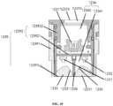
- the housing 1239 includes a first shell 12391 and a second shell 12392 connected to the first shell 12391, such that the accommodating chamber 1236 is also divided into two chambers, namely a first chamber 12361 arranged in the first shell 12391 and a second chamber 12362 arranged in the second shell 12392.
- the first convex lens 1233, the second convex lens 1234, the partition 1235, the light receiver 1232 and the light emitter 1231 are located in the first chamber 12361.
- the connector 1237 is located in the second chamber 12362. In this way, each component has a corresponding installation region, thereby making the arrangement of each component more reasonable.
- the connector 1237 may be disposed in the accommodating chamber 1236 in two modes as follows.
- the connector 1237 is located at the first opening 1238, such that after the connecting component of the external apparatus is inserted into the first opening 1238, the connector 1237 can be connected to the connecting component of the external apparatus; or the connecting component of the external apparatus can be pulled out from the first opening 1238 to disconnect the connector 1237 from the connecting component of the external apparatus, thereby facilitating the use of the cliff sensor.
- the first opening 1238 is located on the second shell 12392 and on the side wall opposite to the first convex lens 1233 and the second convex lens 1234, thereby facilitating the plugging-in of the connector 1237 with the connecting component of the external apparatus.
- the outer edge of the connector 1237 is flush with the edge of the first opening 1238. That is, the connector 1237 is as close to the edge of the first opening 1238 as possible, such that the connector 1237 can come into full contact with the connecting component of the external apparatus, thereby improving the stability of the connection and avoiding the problem of disconnection failure that easily occurs due to small contact between the connector 1237 and the connecting component of the external apparatus.
- the blocking member 12311 may be made of a soft rubber material, for example, thermoplastic polyurethane elastomer rubber or thermoplastic elastomer, etc.
- the blocking member 12311 and the first sub-shell 123921 or the second sub-shell 123922 of the second shell 12392 may be in an integral structure.
- the blocking member 12311 and the first sub-shell 123921 or the second sub-shell 123922 of the second shell 12392 are made of different materials.
- the blocking member 12311 and the housing 1239 are molded by secondary injection molding. Of course, the blocking member 12311 and the first sub-shell 123921 or the second sub-shell 123922 may also be in a split structure.
- the sealing of the second opening 12310 by the blocking member 12311 improves the overall airtightness of the cliff sensor, thereby preventing the service life of the cliff sensor from being reduced due to the fact that dust or moisture from the external environment enter the accommodating chamber 1236 to result in rustiness and corrosion of the connector 1237.
- the connecting wire 12312 extends out of the second opening 12310, such that the connector 1237 is connected to the connecting component of the external apparatus through the connecting wire 12312 extending out of the second opening 12310.
- the self-moving device is based on all the technical solutions of all the above embodiments, it at least has all the beneficial effects brought by the technical solutions of the above embodiments, which will not be repeated one by one here.
- the self-moving device of this embodiment may automatically move in a region to be cleaned and automatically perform operations.
- the self-moving device may be a cleaning robot, such as a sweeping robot 10, a mopping robot, a floor polishing robot or a weeding robot.
- a cleaning robot such as a sweeping robot 10, a mopping robot, a floor polishing robot or a weeding robot.
- this embodiment describes the technical solution of the present disclosure by taking the sweeping robot 10 as an example.
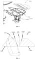
- the sweeping robot 10 may include a machine body 110, a perception module 120, a controller, a drive module, a cleaning system 150, an energy system, and a human-machine interaction module 130.
- the machine body 110 includes a forward portion 111 and a rearward portion 112, and has an approximately circular shape (circular in front and back) or other shapes, including but not limited to an approximately D-shape with a square front and a circular back, and a rectangular or square shape being square in front and back.
- the perception module 120 includes a position determination means 121 located on the machine body 110, a collision sensor arranged on a front collision structure 122 of the forward portion 111 of the machine body 110, a short-distance sensor (wall sensor) located on the side of the machine, a cliff sensor 123 arranged at the lower part of the machine body 110, as well as a magnetometer, an accelerometer, a gyroscope, an odometer and other sensing means arranged inside the machine body 110 and configured to provide the controller with various position information and motion state information of the machine.
- the position determination means 121 includes but is not limited to a camera and a laser distance sensor (LDS).
- the position determination means 121 (such as a camera or a laser sensor) is located on the front side of the body 110, i.e., the frontmost end of the forward portion 111, so as to enable more accurate sensing of the environment in front of the cleaning robot and achieve precise positioning.
- the controller is arranged on a circuit board in the machine body 110, and includes a computing processor, for example, a central processing unit or an application processor, which communicates with a non-transient memory, for example, a hard disk, a flash memory or a random access memory.
- the application processor draws a simultaneous map of the environment where the cleaning robot 10 is located using a localization algorithm (for example, simultaneous localization and mapping, SLAM) according to the obstacle information fed back by the laser distance sensor.
- a localization algorithm for example, simultaneous localization and mapping, SLAM
- the current working state and position of the cleaning robot 10 as well as the current posture (for example, crossing a threshold, crawling onto a carpet, being at the cliff, the upper or lower part being stuck, the dust box being full, the dust box being picked up, etc.) of the cleaning robot 10 are comprehensively determined by combining the distance information and speed information fed back by the sensor provided on the front collision structure 122, the cliff sensor 123, the magnetometer, the accelerometer, the gyroscope, the odometer, and other sensing means, and moreover, specific next action strategies may be given for different situations, so as to enable the cleaning robot 10 to achieve a better cleaning performance and provide better user experience.
- the drive module may manipulate the machine body 110 to travel across the ground based on a drive command with distance and angle information.
- the drive module includes a main drive wheel module, which may control a left wheel 140 and a right wheel 141.
- the main drive wheel module preferably includes a left drive wheel module and a right drive wheel module respectively.
- the left and right drive wheel modules are arranged along a transverse axis defined by the machine body 110.
- the cleaning robot 10 may include one or more driven wheels 142, which include but are not limited to universal wheels.
- the main drive wheel module includes a drive motor and a control circuit that controls the drive motor, and the main drive wheel module may also be connected to a circuit and an odometer that meter a drive current.
- the left wheel 140 and the right wheel 141 may have a biased drop suspension system, which is fastened in a movable manner (for example, attached to the machine body 110 in a rotatable manner) and receives a spring bias that is biased downward and away from the machine body 110.
- the spring bias allows the drive wheels to maintain contact and traction with the ground with a certain landing force, while the cleaning elements of the cleaning robot 10 also contact the ground with a certain pressure.
- the energy system includes rechargeable batteries, for example nickel-metal hydride batteries and lithium batteries.
- the rechargeable batteries may be connected to a charging control circuit, a battery pack charging temperature detection circuit, and a battery undervoltage monitoring circuit, which are then connected to a single-chip microcomputer control circuit.
- the machine body is charged by connecting to a charging pile through a charging electrode 160 disposed on the side or underside of the body.
- the cleaning head 1531 is configured to clean the surface to be cleaned, and the drive unit 1532 is configured to drive the cleaning head 1531 to reciprocate along a target surface, which is a part of the surface to be cleaned.
- the cleaning head 1531 reciprocates along the surface to be cleaned, and a mop is provided on a surface of the cleaning head 1531 in contact with the surface to be cleaned.
- the mop of the cleaning head 1531 is driven by the drive unit 1532 to reciprocate to produce high-frequency friction with the surface to be cleaned, thereby removing stains on the surface to be cleaned; or the mop may be arranged to float and always keep in contact with the surface to be cleaned during the cleaning process, without the need for the drive unit 1532 to drive its reciprocating motion.
- the wet cleaning system 153 may be connected to the machine body 110 through an active lifting module.
- the cleaning robot 10 stops at the base station to clean the cleaning head 1531 of the wet cleaning system 153 and fill the liquid storage tank with water; or when encountering a surface to be cleaned that cannot be cleaned by the wet cleaning system 153, the wet cleaning system 153 is raised through the active lifting module.
Landscapes
- Engineering & Computer Science (AREA)
- Mechanical Engineering (AREA)
- Physics & Mathematics (AREA)
- Optics & Photonics (AREA)
- Robotics (AREA)
- General Physics & Mathematics (AREA)
- Computer Networks & Wireless Communication (AREA)
- Radar, Positioning & Navigation (AREA)
- Remote Sensing (AREA)
- Investigating Or Analysing Materials By Optical Means (AREA)
- Geophysics And Detection Of Objects (AREA)
- Details Of Measuring And Other Instruments (AREA)
- Electric Vacuum Cleaner (AREA)
- Optical Radar Systems And Details Thereof (AREA)
Applications Claiming Priority (2)
| Application Number | Priority Date | Filing Date | Title |
|---|---|---|---|
| CN202210655181.6A CN116998965A (zh) | 2022-06-10 | 2022-06-10 | 一种悬崖传感器及自移动设备 |
| PCT/CN2022/136221 WO2023236466A1 (zh) | 2022-06-10 | 2022-12-02 | 一种悬崖传感器及自移动设备 |
Publications (1)
| Publication Number | Publication Date |
|---|---|
| EP4537726A1 true EP4537726A1 (de) | 2025-04-16 |
Family
ID=88560622
Family Applications (1)
| Application Number | Title | Priority Date | Filing Date |
|---|---|---|---|
| EP22945594.4A Pending EP4537726A1 (de) | 2022-06-10 | 2022-12-02 | Klippensensor und selbstbewegende vorrichtung |
Country Status (7)
| Country | Link |
|---|---|
| US (1) | US20250359721A1 (de) |
| EP (1) | EP4537726A1 (de) |
| JP (1) | JP2025519625A (de) |
| KR (1) | KR20250024052A (de) |
| CN (1) | CN116998965A (de) |
| AU (1) | AU2022462785A1 (de) |
| WO (1) | WO2023236466A1 (de) |
Family Cites Families (9)
| Publication number | Priority date | Publication date | Assignee | Title |
|---|---|---|---|---|
| JPH07318309A (ja) * | 1994-05-26 | 1995-12-08 | Matsushita Electric Works Ltd | レーザ光を用いた距離測定装置 |
| JP2003275157A (ja) * | 2002-03-25 | 2003-09-30 | Matsushita Electric Ind Co Ltd | 移動装置 |
| KR102020210B1 (ko) * | 2013-04-11 | 2019-11-05 | 삼성전자주식회사 | 센서 모듈 및 이를 구비하는 로봇 청소기 |
| JP6182475B2 (ja) * | 2014-02-14 | 2017-08-16 | シャープ株式会社 | 自走式電気掃除機 |
| DE102014116254A1 (de) * | 2014-11-07 | 2016-05-12 | Sick Ag | Sensor |
| US11465293B2 (en) * | 2018-07-31 | 2022-10-11 | Bissell Inc. | Autonomous floor cleaner |
| CN213993432U (zh) * | 2020-09-18 | 2021-08-20 | 深圳市杉川机器人有限公司 | 悬崖传感器和扫地机器人 |
| CN216628445U (zh) * | 2021-02-03 | 2022-05-31 | 深圳市杉川机器人有限公司 | 悬崖传感器和扫地机器人 |
| CN217792902U (zh) * | 2022-06-10 | 2022-11-15 | 北京石头世纪科技股份有限公司 | 一种悬崖传感器及自移动设备 |
-
2022
- 2022-06-10 CN CN202210655181.6A patent/CN116998965A/zh active Pending
- 2022-12-02 KR KR1020257000820A patent/KR20250024052A/ko active Pending
- 2022-12-02 EP EP22945594.4A patent/EP4537726A1/de active Pending
- 2022-12-02 WO PCT/CN2022/136221 patent/WO2023236466A1/zh not_active Ceased
- 2022-12-02 JP JP2024572733A patent/JP2025519625A/ja active Pending
- 2022-12-02 US US18/873,690 patent/US20250359721A1/en active Pending
- 2022-12-02 AU AU2022462785A patent/AU2022462785A1/en active Pending
Also Published As
| Publication number | Publication date |
|---|---|
| CN116998965A (zh) | 2023-11-07 |
| US20250359721A1 (en) | 2025-11-27 |
| JP2025519625A (ja) | 2025-06-26 |
| AU2022462785A1 (en) | 2025-01-30 |
| KR20250024052A (ko) | 2025-02-18 |
| WO2023236466A1 (zh) | 2023-12-14 |
Similar Documents
| Publication | Publication Date | Title |
|---|---|---|
| CN215348699U (zh) | 用于自主式地板清洁器的对接站 | |
| US11998160B2 (en) | Autonomous cleaning device | |
| US11054836B2 (en) | Autonomous mobile robot, method for docking an autonomous mobile robot, control device and smart cleaning system | |
| EP3690591B1 (de) | Autonomer mobiler roboter und ladestationsuchverfahren dafür, steuerungsvorrichtung und intelligentes reinigungssystem | |
| CN205885370U (zh) | 自主清洁设备 | |
| EP3949818B1 (de) | Roboterreiniger | |
| US20260079254A1 (en) | Distance detection apparatus and self-propelled device | |
| CN218500628U (zh) | 清洁设备及系统 | |
| CN217792902U (zh) | 一种悬崖传感器及自移动设备 | |
| EP4537726A1 (de) | Klippensensor und selbstbewegende vorrichtung | |
| CN116264954A (zh) | Lds模组及自动清洁设备 | |
| CN221044886U (zh) | 一种传动装置、自动清洁设备及清洁机器人系统 | |
| CN218451585U (zh) | 自动清洁设备 | |
| CN117406296A (zh) | 悬崖检测装置及方法、自移动设备 | |
| CN117502976A (zh) | 自移动清洁设备及其控制方法 | |
| CN113854900B (zh) | 一种自移动机器人 | |
| CN222800878U (zh) | 一种光学传感器及自移动设备 | |
| US20260083297A1 (en) | Automatic cleaning device, and system | |
| CN207463778U (zh) | 智能清洁设备 | |
| CN117368889A (zh) | 作业区域检测装置、清洁机器人及其作业区域的检测方法 |
Legal Events
| Date | Code | Title | Description |
|---|---|---|---|
| STAA | Information on the status of an ep patent application or granted ep patent |
Free format text: STATUS: THE INTERNATIONAL PUBLICATION HAS BEEN MADE |
|
| PUAI | Public reference made under article 153(3) epc to a published international application that has entered the european phase |
Free format text: ORIGINAL CODE: 0009012 |
|
| STAA | Information on the status of an ep patent application or granted ep patent |
Free format text: STATUS: REQUEST FOR EXAMINATION WAS MADE |
|
| 17P | Request for examination filed |
Effective date: 20250110 |
|
| AK | Designated contracting states |
Kind code of ref document: A1 Designated state(s): AL AT BE BG CH CY CZ DE DK EE ES FI FR GB GR HR HU IE IS IT LI LT LU LV MC ME MK MT NL NO PL PT RO RS SE SI SK SM TR |
|
| DAV | Request for validation of the european patent (deleted) | ||
| DAX | Request for extension of the european patent (deleted) |