EP4537701A1 - Trocknungsvorrichtung - Google Patents
Trocknungsvorrichtung Download PDFInfo
- Publication number
- EP4537701A1 EP4537701A1 EP23202946.2A EP23202946A EP4537701A1 EP 4537701 A1 EP4537701 A1 EP 4537701A1 EP 23202946 A EP23202946 A EP 23202946A EP 4537701 A1 EP4537701 A1 EP 4537701A1
- Authority
- EP
- European Patent Office
- Prior art keywords
- air
- drying device
- mems device
- mems
- flow
- Prior art date
- Legal status (The legal status is an assumption and is not a legal conclusion. Google has not performed a legal analysis and makes no representation as to the accuracy of the status listed.)
- Withdrawn
Links
Images


Classifications
-
- A—HUMAN NECESSITIES
- A45—HAND OR TRAVELLING ARTICLES
- A45D—HAIRDRESSING OR SHAVING EQUIPMENT; EQUIPMENT FOR COSMETICS OR COSMETIC TREATMENTS, e.g. FOR MANICURING OR PEDICURING
- A45D20/00—Hair drying devices; Accessories therefor
- A45D20/04—Hot-air producers
- A45D20/08—Hot-air producers heated electrically
- A45D20/10—Hand-held drying devices, e.g. air douches
- A45D20/12—Details thereof or accessories therefor, e.g. nozzles, stands
-
- A—HUMAN NECESSITIES
- A45—HAND OR TRAVELLING ARTICLES
- A45D—HAIRDRESSING OR SHAVING EQUIPMENT; EQUIPMENT FOR COSMETICS OR COSMETIC TREATMENTS, e.g. FOR MANICURING OR PEDICURING
- A45D20/00—Hair drying devices; Accessories therefor
- A45D20/04—Hot-air producers
-
- A—HUMAN NECESSITIES
- A47—FURNITURE; DOMESTIC ARTICLES OR APPLIANCES; COFFEE MILLS; SPICE MILLS; SUCTION CLEANERS IN GENERAL
- A47K—SANITARY EQUIPMENT; ACCESSORIES THEREFOR, e.g. TOILET ACCESSORIES
- A47K10/00—Body-drying implements; Toilet paper; Holders therefor
- A47K10/48—Drying by means of hot air
-
- A—HUMAN NECESSITIES
- A45—HAND OR TRAVELLING ARTICLES
- A45D—HAIRDRESSING OR SHAVING EQUIPMENT; EQUIPMENT FOR COSMETICS OR COSMETIC TREATMENTS, e.g. FOR MANICURING OR PEDICURING
- A45D2200/00—Details not otherwise provided for in A45D
- A45D2200/20—Additional enhancing means
- A45D2200/207—Vibration, e.g. ultrasound
Definitions
- the invention relates to a drying device, such as a hair dryer or a hand dryer.
- Drying devices such as hairdryers and hand dryers typically include a heating element and a fan for air propulsion, to blow warm air towards an object to be dried (e.g., hair or a hand).
- a heating element e.g., hair or a hand
- a fan for air propulsion
- the fan used in the drying device needs to be of a sufficient size, meaning the drying device itself needs to be of a sufficient size to house the fan.
- fans In addition to the size requirement, fans also have other drawbacks. For example, fans - which are typically driven by a motor - create a large amount of noise when they rotate, which can cause a negative experience for a user of a drying device having such a fan. Energy is required to drive the fan (e.g., to drive the motor), so a drying device having a larger fan will require a larger amount of energy.
- a drying device such as a hair dryer or a hand dryer, which is capable of providing and equivalent or better drying effect as existing drying devices, but does not suffer from issues resulting from having just a fan to generate airflow.
- the inventor of the present disclosure has recognised that such improvements may be realised by providing a drying device that includes a different type of airflow generation device instead of, or in addition to, a fan.
- a drying device includes, among other features, a micro-electromechanical system (MEMS) device that includes one or more vibrating members that, when actuated, vibrate to cause a flow of air that can be used to dry an object.
- MEMS micro-electromechanical system
- a MEMS device is smaller and quieter than many fans traditionally used in drying devices and, therefore, a similar drying effect may be achieved without the drawbacks suffered when using a drying device that uses just a fan for generating airflow.
- a drying device comprising at least one micro-electromechanical system (MEMS) device having at least one vibrating member, the at least one MEMS device configured to generate a flow of air along an airflow path for drying an object; a housing configured to at least partially house the at least one MEMS device; and an air outlet formed in the housing, the air outlet configured to direct the flow of air away from the at least one MEMS device.
- the drying device may further comprise a heat source in thermal communication with the at least one MEMS device, such that heat generated by the heat source is transferred to the flow of air.
- the drying device may comprise a power source electrically connected to and configured to supply power to the at least one MEMS device.
- the power source may be in thermal communication with the at least one MEMS device, such that heat generated by the power source is transferred to the flow of air.
- the drying device may further comprise a heat transfer bonding medium between the at least one MEMS device and the power source.
- the drying device may further comprise a motor configured to drive the fan.
- the drying device may further comprise an air inlet formed in the housing, the air inlet configured to direct ambient air from outside the housing towards the at least one MEMS device.
- the at least one MEMS device may form at least one wall defining the airflow path along which the flow of air is to move.
- At least a portion of the flow of air generated by the MEMS device may be redirected through the housing of the drying device.
- the drying device may, in some embodiments, be configured to at least partially dry a body part of a user.
- the drying device may comprise a hairdryer or a hand dryer.
- the drying device may, for example, comprise a hairdryer and may further comprise a handle to be held by a user during use.
- MEMS micro-electromechanical system
- a MEMS device includes at least one vibrating member which, when actuated (e.g., caused to vibrate), causing movement of air within the MEMS device, which can be directed to cause a flow of air that can be used to dry an object.
- Fig. 1 is a schematic illustration of an example of a drying device 100 according to various embodiments.
- the drying device 100 comprises at least one micro-electromechanical system (MEMS) device 102 having at least one vibrating member (not shown in Fig. 1 ), the at least one MEMS device configured to generate a flow of air along an airflow path for drying an object.
- MEMS micro-electromechanical system
- the arrangement and functionality of the MEMS device 102 is discussed in greater detail below with reference to Fig. 2 .
- the drying device 100 comprises a housing 104 configured to at least partially house the at least one MEMS device 102.
- An air outlet 106 is formed in the housing 104.
- the air outlet 106 is configured to direct the flow of air away from the at least one MEMS device 102.
- the drying device 100 may further comprise an air inlet 108.
- the air inlet 108 may be configured to direct ambient air from outside the housing towards the at least one MEMS device 102.
- the drying device 100 described herein with reference to the Figs. may include features other than those shown.
- the drying device 100 may include one or more components for supporting the MEMS device 100 or other components relative to the housing 104 or relative to one another, components for directing the flow of air (e.g., from the air inlet 108, via the MEMS device 102, to the air outlet 106), a power source or a mechanism for providing power to the MEMS device, and so on.
- the drying device 100 generates a flow of air using at least one MEMS device 102, rather than just a fan.
- Fig. 2 is a schematic illustration of an example of a MEMS device 102 capable of generating a flow of air in the drying device 100.
- the drying device 100 may include or be provided with one or more of any suitable MEMS device 102 that has at least one vibrating member capable of generating a flow of air.
- MEMS device 102 that may be used to generate a flow of air in a drying device 100 is the AirJet (RTM), AirJet (RTM) Mini or AirJet (RTM) Pro by Frore Systems Inc., described briefly below and described in greater detail in US patent publication number 2023/012794 A1 , the content of which is hereby incorporated by reference.
- the vibration plate 210 may comprise a substantially rectangular plate, supported at its central region by the support 212, such that when actuated, the two ends of the vibration plate vibrate up and down.
- the vibration plate may be substantially round, such that, during actuation, edges of the vibration plate are caused to vibrate around its perimeter.
- vents 204, 208 in the upper plate 202 and the lower plate 206 may be varied, and the size, shape and/or location of the vents may be varied depending on the amount of air intended to enter and leave the MEMS device 102.
- vents may be positioned in sidewalls of the MEMS device 102 instead of, or in addition to, vents positioned in the upper plate 202 and the lower plate 206.
- the volume inside the MEMS device 102 (e.g., the volume defined by the upper plate 202, the lower plate 206 and walls of the men device) may be considered to be a chamber, and the size, shape and configuration of the chamber may be chosen based on the intended functionality of the MEMS device, such as the intended frequency at which the vibration plate 210 is to vibrate.
- the vibration plate 210 may be driven at a frequency that is equal to or approximately equal to a resonant frequency of the vibration plate and/or at a frequency that is equal to or approximately equal to a resonant frequency for an acoustic resonance of a pressure wave of air within the MEMS device 102.
- actuation of the vibration plate 210 may be achieved using a piezoelectric, which may be located outside of the MEMS device 102, or within the MEMS device, such as within the vibration plate itself or within the support 212.
- the flow of air generated by actuation of the vibration plate 210, and leaving the MEMS device via the vent(s) 208 can be directed towards an object to be dried.
- Vibration of the vibration plate 210 may generate heat, causing a temperature of air within the MEMS device 102 to increase, such that air leaving the MEMS device via the vent(s) 208 is hotter than air entering the MEMS device via the vent 204.
- a heat source may be used to generate heat to warm the air.
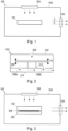
- Fig. 3 is a schematic illustration of a further example of a drying device 100.
- the drying device may further comprise a heat source 302 in thermal communication with the at least one MEMS device 102, such that heat generated by the heat source is transferred to the flow of air.
- the deflection plate 214 may also serve to conduct heat from the heat source 302 to air passing through the vent(s) 208 impinging the deflection plate 214.
- the deflection plate 214 may be made of a material having good thermal conduction properties.
- the heat source 302 may be coupled to or connected to the deflection plate 214 directly, such that as much heat as possible is transferred from the heat source to the air leaving the MEMS device 102.
- the drying device 100 may further comprise a heat transfer bonding medium 304 between the at least one MEMS device 102 and the heat source 302.
- the heat transfer bonding medium 304 may be provided between the heat source 302 and the deflection plate 214 of the MEMS device 102.
- the heat transfer bonding medium 304 may, for example, comprise a paste or adhesive having good thermal conduction properties, so that as much heat as possible is transferred from the heat source 302 via the heat transfer bonding medium and the deflection plate 214 into the air leaving the MEMS device 102.
- the drying device 100 may further comprise a power source electrically connected to and configured to supply power to the at least one MEMS device 102.
- the power source may be configured to provide power to one or more other components of the drying device 100.
- the power source may, for example, comprise one or more batteries.
- the power source may be in thermal communication with the at least one MEMS device 102, such that heat generated by the power source is transferred to the flow of air.
- the heat source 302 may comprise a power source.
- the drying device 100 may comprise a heat source 302 and a power source, and in such examples, both the heat source and the power source may be in thermal communication with the at least one MEMS device 102 (e.g., in thermal communication with the deflection plate 214 of the MEMS device), such that heat generated by both the heat source and the power source is used to increase the temperature of air leaving the MEMS device 102.
- the drying device 100 may further comprise a heat transfer bonding medium between the at least one MEMS device 102 and the power source.
- the heat transfer bonding medium used between the power source and the MEMS device 102 may be the same as the heat transfer bonding medium used between the heat source 302 and the MEMS device.
- a plurality of MEMS devices 102 i.e., three MEMS devices in this case
- increased flow of air may be achieved due to the increased number of MEMS devices 102, each having a vibrating member.
- a heat source (not shown in Fig. 6 ) may be positioned in the centre of the prism, so that heat can be transferred to each of the MEMS devices 102.
- Fig. 7 for MEMS devices 102 are arranged to form a rectangular prism shape.
- the rectangular prism arrangement allows for a heat source (not shown in Fig. 7 ) to be positioned in the centre of the prism, so that heat can be transferred to each of the MEMS devices 102.
- vents 204, 208 may be provided in the upper plate 202, the lower plate 206 and/or in one or more walls of the MEMS device 102.
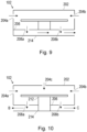
- Figs. 9 and 10 are schematic illustrations of further examples of MEMS devices 102 having different configurations of vents 204, 208.
- vents 204a and 204b are provided in sidewalls of the MEMS device 102 for enabling air to flow into the MEMS device, and the vents 208a and 208b are provided in the lower plate 206 for allowing air to exit the MEMS device.
- vents 204a and 204b are provided in the lower plate 206 for allowing air to exit the MEMS device.
- vents 204a, 204b and 204c are provided in the upper plate 202 and the sidewalls of the MEMS device 102, and the vents 208a and 208b are provided in the lower plate 206.
- the support 212 extends beyond the lower plate 206, and connects to the deflection plate 214.
- air that leaves of the MEMS device 102 via the vent 208a is directed in a first direction indicated by the arrow B
- air that leaves the MEMS device via the vent 208b is directed in a second direction indicated by the arrow C.
- the direction indicated by the arrow B is opposite to the direction indicated by the arrow C. In this way, it is possible to generate two flows of air, for example to enable multiple objects to be dried at the same time.
- a flow of air generated by the at least one MEMS device 102 is directed out of the housing 104 of the drying device 100, towards an object to be dried.
- at least a portion of the flow of air generated by the at least one MEMS device 102 may be redirected through the housing of the drying device 100.
- air may flow through a duct or cavity in the housing 104 of the drying device 100, and an object or objects to be dried may be placed within the duct or cavity to be dried by the flow of air.
- their hair close to the drying device 100, and the flow of air through the duct or cavity may cause the user's hair to be sucked or drawn into the drying device.
- the flow of air through the duct or cavity may pass over the hair in the drying device 100, causing it to be dried.
- the hair dryer 1100 may comprise the drying device 100 and further comprises a handle 1102 to be held by a user during use.
- the handle 1102 may include one or more controls, such as buttons or switches that the user may use to operate the hair dryer 1100, for example to switch the hairdryer on and off, to adjust the frequency of vibration of the vibration plate 210 and/or to adjust the temperature to which air is to be heated by the heat source 302.
- the hand dryer 1200 may comprise the drying device 100, and may be configured such that a user positions their hands beneath the air outlet 106 to be dried.
- Other configurations of the drying device 100 may be implemented into devices used to dry other items.
- a drying device that can provide an improved user experience due to reduced noise generation (e.g., as a result of using a MEMS device instead of a fan to generate a flow of air) and that is capable of effectively and efficiently drying an object.
- a computer program may be stored or distributed on a suitable medium, such as an optical storage medium or a solid-state medium supplied together with or as part of other hardware, but may also be distributed in other forms, such as via the Internet or other wired or wireless telecommunication systems. Any reference signs in the claims should not be construed as limiting the scope.
Landscapes
- Health & Medical Sciences (AREA)
- Public Health (AREA)
- Drying Of Solid Materials (AREA)
Priority Applications (2)
| Application Number | Priority Date | Filing Date | Title |
|---|---|---|---|
| EP23202946.2A EP4537701A1 (de) | 2023-10-11 | 2023-10-11 | Trocknungsvorrichtung |
| PCT/EP2024/077952 WO2025078278A1 (en) | 2023-10-11 | 2024-10-04 | Drying device |
Applications Claiming Priority (1)
| Application Number | Priority Date | Filing Date | Title |
|---|---|---|---|
| EP23202946.2A EP4537701A1 (de) | 2023-10-11 | 2023-10-11 | Trocknungsvorrichtung |
Publications (1)
| Publication Number | Publication Date |
|---|---|
| EP4537701A1 true EP4537701A1 (de) | 2025-04-16 |
Family
ID=88372197
Family Applications (1)
| Application Number | Title | Priority Date | Filing Date |
|---|---|---|---|
| EP23202946.2A Withdrawn EP4537701A1 (de) | 2023-10-11 | 2023-10-11 | Trocknungsvorrichtung |
Country Status (2)
| Country | Link |
|---|---|
| EP (1) | EP4537701A1 (de) |
| WO (1) | WO2025078278A1 (de) |
Citations (4)
| Publication number | Priority date | Publication date | Assignee | Title |
|---|---|---|---|---|
| US20050047764A1 (en) * | 2003-08-26 | 2005-03-03 | Teh-Liang Lo | Multiple-setting portable dryer and circuit designs thereof |
| JP2013103060A (ja) * | 2011-11-16 | 2013-05-30 | Panasonic Corp | ヘアケア装置 |
| WO2021230529A1 (ko) * | 2020-05-12 | 2021-11-18 | 신동혁 | 초음파를 이용한 수분 제거 장치 및 이를 구비한 핸드 드라이어 |
| US20230012794A1 (en) | 2021-07-09 | 2023-01-19 | Frore Systems Inc. | Driving of piezoelectrics for mems-based cooling systems |
-
2023
- 2023-10-11 EP EP23202946.2A patent/EP4537701A1/de not_active Withdrawn
-
2024
- 2024-10-04 WO PCT/EP2024/077952 patent/WO2025078278A1/en active Pending
Patent Citations (4)
| Publication number | Priority date | Publication date | Assignee | Title |
|---|---|---|---|---|
| US20050047764A1 (en) * | 2003-08-26 | 2005-03-03 | Teh-Liang Lo | Multiple-setting portable dryer and circuit designs thereof |
| JP2013103060A (ja) * | 2011-11-16 | 2013-05-30 | Panasonic Corp | ヘアケア装置 |
| WO2021230529A1 (ko) * | 2020-05-12 | 2021-11-18 | 신동혁 | 초음파를 이용한 수분 제거 장치 및 이를 구비한 핸드 드라이어 |
| US20230012794A1 (en) | 2021-07-09 | 2023-01-19 | Frore Systems Inc. | Driving of piezoelectrics for mems-based cooling systems |
Also Published As
| Publication number | Publication date |
|---|---|
| WO2025078278A1 (en) | 2025-04-17 |
Similar Documents
| Publication | Publication Date | Title |
|---|---|---|
| AU2024201467B2 (en) | Apparatus and method for drying hair | |
| US11466896B2 (en) | Heating blower and heating device | |
| CN217609893U (zh) | 吹风机 | |
| JPH05130950A (ja) | 熱風ドライヤ− | |
| EP4537701A1 (de) | Trocknungsvorrichtung | |
| CN210290191U (zh) | 风扇组件以及风扇和镜子组件 | |
| CN215899071U (zh) | 干燥设备 | |
| CN107781932B (zh) | 干燥机及干燥机的控制方法 | |
| CN213820195U (zh) | 吹风机 | |
| CN212563735U (zh) | 一种挂脖风扇 | |
| CN112336039A (zh) | 一种便携式双层风道吹风机 | |
| KR100406213B1 (ko) | 브러시가 부착된 드라이어 | |
| US3650041A (en) | Hair dryer | |
| WO2025082783A1 (en) | Drying device | |
| WO2021224302A1 (en) | Hair dryer | |
| US11445792B1 (en) | Hair dry blower | |
| CN114869039B (zh) | 一种便携式吹风筒 | |
| US3046673A (en) | Hair dryer | |
| JP7545798B2 (ja) | ヘアドライヤ | |
| CN214509934U (zh) | 一种便携式双层风道吹风机 | |
| JP7545797B2 (ja) | ヘアドライヤ | |
| CN118370439B (zh) | 一种无线吹风机 | |
| JP2002188849A (ja) | 浴室暖房乾燥機 | |
| EP4527243A1 (de) | Haartrockner | |
| EP3906808A1 (de) | Haartrockner |
Legal Events
| Date | Code | Title | Description |
|---|---|---|---|
| PUAI | Public reference made under article 153(3) epc to a published international application that has entered the european phase |
Free format text: ORIGINAL CODE: 0009012 |
|
| STAA | Information on the status of an ep patent application or granted ep patent |
Free format text: STATUS: THE APPLICATION HAS BEEN PUBLISHED |
|
| AK | Designated contracting states |
Kind code of ref document: A1 Designated state(s): AL AT BE BG CH CY CZ DE DK EE ES FI FR GB GR HR HU IE IS IT LI LT LU LV MC ME MK MT NL NO PL PT RO RS SE SI SK SM TR |
|
| STAA | Information on the status of an ep patent application or granted ep patent |
Free format text: STATUS: THE APPLICATION IS DEEMED TO BE WITHDRAWN |
|
| 18D | Application deemed to be withdrawn |
Effective date: 20251017 |