EP4535935A1 - Jet flow soldering device - Google Patents
Jet flow soldering device Download PDFInfo
- Publication number
- EP4535935A1 EP4535935A1 EP23823865.3A EP23823865A EP4535935A1 EP 4535935 A1 EP4535935 A1 EP 4535935A1 EP 23823865 A EP23823865 A EP 23823865A EP 4535935 A1 EP4535935 A1 EP 4535935A1
- Authority
- EP
- European Patent Office
- Prior art keywords
- substrate
- supply port
- cooling unit
- molten solder
- unit
- Prior art date
- Legal status (The legal status is an assumption and is not a legal conclusion. Google has not performed a legal analysis and makes no representation as to the accuracy of the status listed.)
- Pending
Links
Images








Classifications
-
- B—PERFORMING OPERATIONS; TRANSPORTING
- B23—MACHINE TOOLS; METAL-WORKING NOT OTHERWISE PROVIDED FOR
- B23K—SOLDERING OR UNSOLDERING; WELDING; CLADDING OR PLATING BY SOLDERING OR WELDING; CUTTING BY APPLYING HEAT LOCALLY, e.g. FLAME CUTTING; WORKING BY LASER BEAM
- B23K1/00—Soldering, e.g. brazing, or unsoldering
- B23K1/08—Soldering by means of dipping in molten solder
-
- B—PERFORMING OPERATIONS; TRANSPORTING
- B23—MACHINE TOOLS; METAL-WORKING NOT OTHERWISE PROVIDED FOR
- B23K—SOLDERING OR UNSOLDERING; WELDING; CLADDING OR PLATING BY SOLDERING OR WELDING; CUTTING BY APPLYING HEAT LOCALLY, e.g. FLAME CUTTING; WORKING BY LASER BEAM
- B23K1/00—Soldering, e.g. brazing, or unsoldering
- B23K1/0008—Soldering, e.g. brazing, or unsoldering specially adapted for particular articles or work
- B23K1/0016—Soldering of electronic components
-
- B—PERFORMING OPERATIONS; TRANSPORTING
- B23—MACHINE TOOLS; METAL-WORKING NOT OTHERWISE PROVIDED FOR
- B23K—SOLDERING OR UNSOLDERING; WELDING; CLADDING OR PLATING BY SOLDERING OR WELDING; CUTTING BY APPLYING HEAT LOCALLY, e.g. FLAME CUTTING; WORKING BY LASER BEAM
- B23K3/00—Tools, devices or special appurtenances for soldering, e.g. brazing, or unsoldering, not specially adapted for particular methods
- B23K3/08—Auxiliary devices therefor
- B23K3/085—Cooling, heat sink or heat shielding means
-
- B—PERFORMING OPERATIONS; TRANSPORTING
- B23—MACHINE TOOLS; METAL-WORKING NOT OTHERWISE PROVIDED FOR
- B23K—SOLDERING OR UNSOLDERING; WELDING; CLADDING OR PLATING BY SOLDERING OR WELDING; CUTTING BY APPLYING HEAT LOCALLY, e.g. FLAME CUTTING; WORKING BY LASER BEAM
- B23K1/00—Soldering, e.g. brazing, or unsoldering
- B23K1/08—Soldering by means of dipping in molten solder
- B23K1/085—Wave soldering
-
- B—PERFORMING OPERATIONS; TRANSPORTING
- B23—MACHINE TOOLS; METAL-WORKING NOT OTHERWISE PROVIDED FOR
- B23K—SOLDERING OR UNSOLDERING; WELDING; CLADDING OR PLATING BY SOLDERING OR WELDING; CUTTING BY APPLYING HEAT LOCALLY, e.g. FLAME CUTTING; WORKING BY LASER BEAM
- B23K1/00—Soldering, e.g. brazing, or unsoldering
- B23K1/20—Preliminary treatment of work or areas to be soldered, e.g. in respect of a galvanic coating
- B23K1/203—Fluxing, i.e. applying flux onto surfaces
-
- B—PERFORMING OPERATIONS; TRANSPORTING
- B23—MACHINE TOOLS; METAL-WORKING NOT OTHERWISE PROVIDED FOR
- B23K—SOLDERING OR UNSOLDERING; WELDING; CLADDING OR PLATING BY SOLDERING OR WELDING; CUTTING BY APPLYING HEAT LOCALLY, e.g. FLAME CUTTING; WORKING BY LASER BEAM
- B23K3/00—Tools, devices or special appurtenances for soldering, e.g. brazing, or unsoldering, not specially adapted for particular methods
- B23K3/06—Solder feeding devices; Solder melting pans
- B23K3/0607—Solder feeding devices
-
- B—PERFORMING OPERATIONS; TRANSPORTING
- B23—MACHINE TOOLS; METAL-WORKING NOT OTHERWISE PROVIDED FOR
- B23K—SOLDERING OR UNSOLDERING; WELDING; CLADDING OR PLATING BY SOLDERING OR WELDING; CUTTING BY APPLYING HEAT LOCALLY, e.g. FLAME CUTTING; WORKING BY LASER BEAM
- B23K3/00—Tools, devices or special appurtenances for soldering, e.g. brazing, or unsoldering, not specially adapted for particular methods
- B23K3/06—Solder feeding devices; Solder melting pans
- B23K3/0607—Solder feeding devices
- B23K3/0638—Solder feeding devices for viscous material feeding, e.g. solder paste feeding
-
- B—PERFORMING OPERATIONS; TRANSPORTING
- B23—MACHINE TOOLS; METAL-WORKING NOT OTHERWISE PROVIDED FOR
- B23K—SOLDERING OR UNSOLDERING; WELDING; CLADDING OR PLATING BY SOLDERING OR WELDING; CUTTING BY APPLYING HEAT LOCALLY, e.g. FLAME CUTTING; WORKING BY LASER BEAM
- B23K3/00—Tools, devices or special appurtenances for soldering, e.g. brazing, or unsoldering, not specially adapted for particular methods
- B23K3/06—Solder feeding devices; Solder melting pans
- B23K3/0646—Solder baths
- B23K3/0653—Solder baths with wave generating means, e.g. nozzles, jets, fountains
-
- H—ELECTRICITY
- H05—ELECTRIC TECHNIQUES NOT OTHERWISE PROVIDED FOR
- H05K—PRINTED CIRCUITS; CASINGS OR CONSTRUCTIONAL DETAILS OF ELECTRIC APPARATUS; MANUFACTURE OF ASSEMBLAGES OF ELECTRICAL COMPONENTS
- H05K3/00—Apparatus or processes for manufacturing printed circuits
- H05K3/30—Assembling printed circuits with electric components, e.g. with resistors
- H05K3/32—Assembling printed circuits with electric components, e.g. with resistors electrically connecting electric components or wires to printed circuits
- H05K3/34—Assembling printed circuits with electric components, e.g. with resistors electrically connecting electric components or wires to printed circuits by soldering
-
- H—ELECTRICITY
- H05—ELECTRIC TECHNIQUES NOT OTHERWISE PROVIDED FOR
- H05K—PRINTED CIRCUITS; CASINGS OR CONSTRUCTIONAL DETAILS OF ELECTRIC APPARATUS; MANUFACTURE OF ASSEMBLAGES OF ELECTRICAL COMPONENTS
- H05K3/00—Apparatus or processes for manufacturing printed circuits
- H05K3/30—Assembling printed circuits with electric components, e.g. with resistors
- H05K3/32—Assembling printed circuits with electric components, e.g. with resistors electrically connecting electric components or wires to printed circuits
- H05K3/34—Assembling printed circuits with electric components, e.g. with resistors electrically connecting electric components or wires to printed circuits by soldering
- H05K3/3465—Application of solder
- H05K3/3468—Application of molten solder, e.g. dip soldering
-
- H—ELECTRICITY
- H05—ELECTRIC TECHNIQUES NOT OTHERWISE PROVIDED FOR
- H05K—PRINTED CIRCUITS; CASINGS OR CONSTRUCTIONAL DETAILS OF ELECTRIC APPARATUS; MANUFACTURE OF ASSEMBLAGES OF ELECTRICAL COMPONENTS
- H05K3/00—Apparatus or processes for manufacturing printed circuits
- H05K3/30—Assembling printed circuits with electric components, e.g. with resistors
- H05K3/32—Assembling printed circuits with electric components, e.g. with resistors electrically connecting electric components or wires to printed circuits
- H05K3/34—Assembling printed circuits with electric components, e.g. with resistors electrically connecting electric components or wires to printed circuits by soldering
- H05K3/3494—Heating processes for reflow soldering
-
- B—PERFORMING OPERATIONS; TRANSPORTING
- B23—MACHINE TOOLS; METAL-WORKING NOT OTHERWISE PROVIDED FOR
- B23K—SOLDERING OR UNSOLDERING; WELDING; CLADDING OR PLATING BY SOLDERING OR WELDING; CUTTING BY APPLYING HEAT LOCALLY, e.g. FLAME CUTTING; WORKING BY LASER BEAM
- B23K2101/00—Articles made by soldering, welding or cutting
- B23K2101/36—Electric or electronic devices
- B23K2101/42—Printed circuits
Definitions
- the present invention provides a jet soldering apparatus capable of more reliably preventing embrittlement of solder by cooling the solder at an earlier timing as compared with an aspect using only a cooling zone in the related art.
- a jet soldering apparatus may comprise:
- the lower cooling unit may be positioned on a downstream side of the upper cooling unit in the conveyance direction of the substrate.
- the cooling unit may supply the gas toward a downstream side of the conveyance direction of the substrate.
- the cooling unit may supply air at a room temperature as the gas.
- the jet soldering apparatus may comprise a notification unit that notifies that the temperature of the substrate is out of a predetermined temperature range when the temperature of the substrate measured by the measurement unit is out of the predetermined temperature range.
- the fluxer 10 is used to apply flux to the conveyed substrate 200.
- the flux may include a solvent, an activator, and the like.
- the fluxer 10 may be provided with a plurality of coating apparatuses.
- the type of flux may be selectively used according to the type of solder and the type of the substrate 200.
- a temperature of the molten solder S is generally a melting temperature of the solder +30°C.
- Sn-58Bi a solder alloy including Bi: 58% by mass and Sn as a balance. Melting point: 139°C, tensile strength: 76.5 MPs, and elongation: 27%) instead of SAC305 (a solder alloy including: Ag: 3% by mass, Cu: 0.5% by mass, and Sn as a balance.
- a plurality of waves (convex shapes) of the molten solder S supplied from the first supply port 125 can be prevented from being crushed by the molten solder S supplied from the second supply port 135, and both dynamic supply of the molten solder S from the first supply port 125 and static supply of the molten solder S from the second supply port 135 can be provided in a well-balanced manner. As illustrated in FIG.
- the total amount of molten solder S per unit time supplied from the first openings 126 and the total amount of molten solder S per unit time supplied from the second opening 136 which is the secondary jet nozzle may be changed according to the type of the substrate 200.
- a supply amount of the corresponding molten solder S may be read from the storage unit 60 by the control unit 50, and the molten solder S may be supplied from the first openings 126 and the second opening 136 by being adjusted to the read supply amount.
- the operation unit 70 may be capable of reading code information such as a bar code, and the control unit 50 may automatically adjust the supply amount of the molten solder S to the substrate 200 by reading the code information of the substrate 200.
- a downstream adjusting part 182 extending in a horizontal direction or descending downward toward the downstream side may be provided (see FIG. 3 ).
- a height of the downstream adjusting part 182 may be appropriately changed.
- An upstream adjusting part 181 extending in the horizontal direction or rising upward toward the downstream side may be provided on an upstream side of the first supply port 125 in the substrate conveyance direction A.
- the upstream adjusting part 181 and the downstream adjusting part 182 may be linearly inclined, or may be inclined so as to draw an arc in a longitudinal cross section (see FIG. 6 ).
- a height adjustment of the upstream adjusting part 181 and the downstream adjusting part 182 may be manually performed, or may be automatically performed in response to a command from the control unit 50.
- the command from the control unit 50 may be issued on the basis of the identification information of the substrate 200. Adjusting the heights of the upstream adjusting part 181 and the downstream adjusting part 182 as described above is also advantageous in that the amount of the molten solder S supplied to the substrate 200 can be adjusted.
- the distance between the first supply port 125 and the second supply port 135 can be further shortened. Therefore, it is advantageous in that it is possible to realize an aspect in which the molten solder S is not separated from the substrate 200 conveyed by the conveyance unit 5 between the first supply port 125 and the second supply port 135 while further reducing the amount of the molten solder S supplied from the second supply port 135.
- the cooling unit may have a lower cooling unit 330 positioned at a position lower than the conveyance rail 6 of the substrate 200 and above the storage tank 110, and an upper cooling unit 310 provided at a position higher than the conveyance rail 6 and an upper position of the storage tank 110.
- "provided at an upper position of the storage tank 110” means that when a straight line is drawn in an upward direction (vertical direction) from an end part of the storage tank 110 to divide the region, at least a part exists in a region ⁇ divided by the straight line.
- the lower cooling unit 330 directly cools the solder attached to the substrate 200, which is large from the viewpoint of a cooling effect. Therefore, when only one of the upper cooling unit 310 and the lower cooling unit 330 is to be installed, installing the lower cooling unit 330 is considered as a first candidate.
- the upper cooling unit 310 and/or the lower cooling unit 330 may have a slit-shaped opening for supplying gas, or may have a plurality of small-diameter openings.
- the wind speed of the gas supplied from the upper cooling unit 310 and/or the lower cooling unit 330 may be about several meters to several tens of meters per second.
- the upper cooling unit 310 and the lower cooling unit 330 may supply air at a room temperature as the gas.
- the upper cooling unit 310 may have an upper main body 311 extending orthogonal to the substrate conveyance direction, and an upper supply port 315 provided on a side surface of the upper main body 311 and jetting and supplying gas such as air (see FIG. 5 ).
- the upper supply port 315 may be a linear slit as illustrated in FIG. 5 , but may be provided with a plurality of small openings or protruding nozzles (see FIGS. 6 and 7 ).
- the upper main body 311 may extend across the pair of conveyance rails 6 as illustrated in FIG. 9 , or may extend between the pair of conveyance rails 6 as illustrated in FIG. 2 . By providing such an upper cooling unit 310, the entire substrate 200 can be quickly cooled.
- the slit-shaped first lower supply port 335a and the second lower supply port 335b including a plurality of nozzles are provided.
- the first lower supply port 335a has an effect of cooling the solder on the surface and mainly has a function of cooling and curing the solder.
- the first lower supply port 335a functions as a first cooling unit for cooling the solder.
- the second lower supply port 335b including a plurality of nozzles mainly has a function of cooling the substrate 200, and exerts the effect performed in the cooling zone in the related art.
- the second lower supply port 335b functions as a second cooling unit for cooling the substrate 200. Adopting such an aspect is advantageous in that the substrate can be cooled by the second lower supply port 335b while the solder is quickly cured by the first lower supply port 335a.
- the upper supply port 315 may also have a slit-shaped first upper supply port 315a and a second upper supply port 315b including a plurality of nozzles (see FIG. 6 ).
- the first upper supply port 315a has an effect of cooling the solder on the surface, and may mainly have a function of cooling and curing the solder. In this case, the first upper supply port 315a functions as a first cooling unit for cooling the solder.
- the second upper supply port 315b including a plurality of nozzles mainly has a function of cooling the substrate 200, and may exhibit the effect performed in the cooling zone in the related art. In this case, the second upper supply port 315b functions as a second cooling unit for cooling the substrate 200.
- the first upper supply port 315a may also be provided with a return part (not illustrated) that faces the downstream side in the substrate conveyance direction A and allows the gas supplied from the first upper supply port 315a to flow toward the downstream side in the substrate conveyance direction A.
- first lower supply port 335a and the first upper supply port 315a may be provided, and the second lower supply port 335b and the second upper supply port 315b may not be provided (see FIG. 7 ).
- the lower cooling unit 330 may be positioned on the downstream side of the upper cooling unit 310 in the conveyance direction of the substrate 200.
- the lower cooling unit 330 is too close to the second supply port 135, there is a possibility that the lower cooling unit 330 may be covered with the molten solder S supplied from the first supply port 125 and the second supply port 135, and thus, it is not possible to install the lower cooling unit 330 considerably close to the second supply port 135.
- the upper cooling unit 310 since there is a low possibility that the upper cooling unit 310 is covered with the molten solder S supplied from the first supply port 125 and the second supply port 135, the upper cooling unit 310 can be installed close to the second supply port 135 when viewed along the conveyance direction of the substrate 200.
- the region where the molten solder S is supplied to the substrate 200 can be shortened, and as a result, it is also advantageous in that the timing of starting the cooling of the solder by the upper cooling unit 310 and the lower cooling unit 330 on the storage tank 110 can be advanced.
- the conveyance unit 5 conveys the substrate 200 coated with the flux by the fluxer 10 to the preheater unit 15.
- the preheater unit 15 heats the substrate 200 to a predetermined temperature.
- the conveyance unit 5 conveys the substrate 200 heated to the predetermined temperature by the preheater unit to the jet soldering apparatus 100.
- the jet soldering apparatus 100 solders a predetermined part of the substrate 200. While the jet soldering apparatus 100 is supplying the molten solder S, the molten solder S supplied from the first supply port 125 and the molten solder S supplied from the second supply port 135 are mixed, and the molten solder S is supplied to above the conveyance rail 6.
- the molten solder S is configured not to be separated from the substrate 200 conveyed by the conveyance unit 5 between the first supply port 125 and the second supply port 135.
- the molten solder S supplied from the first supply port 125 pushes up the molten solder S supplied from the second supply port 135, and a plurality of convex shapes corresponding to the first openings 126 are formed by the molten solder S.
- the amount of the molten solder S supplied from the first supply port 125 and the second supply port 135 can be adjusted using two or more pumps as described above.
- the wind direction from the lower cooling unit 330 may be changeable by changing the direction of the protruding nozzle of the lower cooling unit 330.
- the positions of the upper supply port 315 and the lower supply ports 335a and 335b can be appropriately changed.
- the positions of the lower supply ports 335a and 335b in the horizontal direction may be adjustable by being extendable (an aspect of a movable aspect) along the horizontal direction.
- One or both of the upper cooling unit 310 and the lower cooling unit 330 may be movable also in the vertical direction.
- a measurement unit 400 that measures the temperature of the substrate 200 after being cooled by the upper cooling unit 310 and the lower cooling unit 330 may be provided (see FIGS. 14 to 17 ). By measuring the temperature of the substrate 200 conveyed by the measurement unit 400 in this manner, it is possible to check and manage whether or not solder curing or cooling immediately after soldering for achieving the solder curing is appropriately performed.
- the measurement unit 400 may be installed at a position before the substrate 200 is cooled by the cooler 20.
- the measurement unit 400 may be installed immediately downstream side of the lower cooling unit 330 in the substrate conveyance direction A (see FIGS. 16 and 17 ).
- the measurement unit 400 may be attached to a guide part 440 including a slide rail or the like extending in the horizontal direction, in a direction orthogonal to the substrate conveyance direction A (see FIGS. 14 and 15A ).
- the measurement unit 400 is movable along the guide part 440.
- angle adjustment and vertical height adjustment of the measurement unit 400 with respect to the guide part 440 may be possible (see FIG. 15B ).
- the position of the guide part 440 which includes a slide rail or the like, in the vertical direction may be changeable.
- the position of the guide part 440 along the substrate conveyance direction A may be changeable.
- a knurling knob 441 is illustrated, and by loosening the knurling knob 441, a measurement unit fixing member 443 to which the measurement unit 400 is attached can move along the guide part 440, and by tightening the knurling knob 441, the position of the measurement unit fixing member 443 in the horizontal direction with respect to the guide part 440 is fixed.
- a measurement unit fixing member 443 to which the measurement unit 400 is attached can move along the guide part 440, and by tightening the knurling knob 441, the position of the measurement unit fixing member 443 in the horizontal direction with respect to the guide part 440 is fixed.
- the control unit 50 may transmit a signal such as a control signal for stopping the carry-in of the substrate 200 to an external device 500 (see FIG. 17 ) positioned on the upstream side of the jet soldering apparatus 100 such as a component mounting device.
- an external device 500 see FIG. 17
- the predetermined temperature range may be input from the operation unit 70 or may be read from information stored in the storage unit 60.
- a notification unit 430 such as an alarm device that notifies that the temperature of the substrate 200 is out of the predetermined temperature range may be provided (see FIG. 14 ).
- a notification unit 430 such as an alarm device that notifies that the temperature of the substrate 200 is out of the predetermined temperature range
- Information may be transmitted to the notification unit 430 directly from the measurement unit 400 or via the thermometer amplifier 405 or the like.
- the display unit 410 may function as the notification unit. In this case, the display unit 410 may display a warning when the temperature of the substrate 200 is out of the predetermined temperature range.
Landscapes
- Engineering & Computer Science (AREA)
- Mechanical Engineering (AREA)
- Manufacturing & Machinery (AREA)
- Microelectronics & Electronic Packaging (AREA)
- Molten Solder (AREA)
- Electric Connection Of Electric Components To Printed Circuits (AREA)
Abstract
Description
- The present invention relates to a jet soldering apparatus that supplies molten solder to a substrate.
- In the related art, a jet soldering apparatus for supplying molten solder to a substrate is known, and a cooling zone for cooling the substrate is installed. For example,
JP 2011-222783 A - As a result of examination by the inventors, it has been found that when the substrate is not cooled to the cooling zone in which the cooler disclosed in
JP 2011-222783 A - The present invention provides a jet soldering apparatus capable of more reliably preventing embrittlement of solder by cooling the solder at an earlier timing as compared with an aspect using only a cooling zone in the related art.
- A jet soldering apparatus according to the present invention may comprise:
- a storage tank configured to store molten solder;
- a supply port for supplying the molten solder to a substrate; and
- a cooling unit that is positioned on a downstream side of the supply port in a conveyance direction of the substrate, is provided at an upper position of the storage tank, and is configured to supply gas.
- In the jet soldering apparatus according to
concept 1,
the cooling unit may have a lower cooling unit configured to supply the gas from below to the substrate conveyed, and an upper cooling unit configured to supply the gas from upper to the substrate conveyed. - In the jet soldering apparatus according to
concept 2,
the lower cooling unit may be positioned on a downstream side of the upper cooling unit in the conveyance direction of the substrate. - In the jet soldering apparatus according to any one of
concepts 1 to 3,
the cooling unit may supply the gas toward a downstream side of the conveyance direction of the substrate. - In the jet soldering apparatus according to
concept 4, - the cooling unit may have a lower cooling unit configured to supply the gas from below to the substrate conveyed, and an upper cooling unit configured to supply the gas from upper to the substrate conveyed,
- the upper cooling unit may supply the gas toward obliquely downward along the conveyance direction of the substrate, and
- the lower cooling unit may supply the gas toward obliquely upward along the conveyance direction of the substrate.
- In the jet soldering apparatus according to any one of
concepts 1 to 5,
the cooling unit may have a first cooling unit for cooling the solder supplied to the substrate, and a second cooling unit for cooling the substrate. - In the jet soldering apparatus according to any one of
concepts 1 to 6,
the cooling unit may supply air at a room temperature as the gas. - In the jet soldering apparatus according to any one of
concepts 1 to 7, - the supply port may have a first supply port for supplying the molten solder provided at a first housing, and a second supply port for supplying the molten solder provided at a second housing, and
- a part where the molten solder falls may not be provided between the first supply port and the second supply port along the conveyance direction of the substrate.
- The jet soldering apparatus according to any one of
concepts 1 to 8 may comprise a measurement unit that measures a temperature of the substrate after being cooled by the cooling unit. - The jet soldering apparatus according to concept 9 may comprise a display unit that displays the temperature of the substrate measured by the measurement unit.
- In the jet soldering apparatus according to
concept 9 or 10,
wherein when the temperature of the substrate measured by the measurement unit is out of a predetermined temperature range, a signal may be transmitted for stopping a carry-in of the substrate. - The jet soldering apparatus according to any one of concepts 9 to 11 may comprise a notification unit that notifies that the temperature of the substrate is out of a predetermined temperature range when the temperature of the substrate measured by the measurement unit is out of the predetermined temperature range.
- The present invention provides a jet soldering apparatus capable of more reliably preventing embrittlement of solder by cooling the solder at an earlier timing as compared with an aspect using only a cooling zone in the related art.
-
-
FIG. 1 is an upper plan view illustrating a soldering apparatus according to the present embodiment. -
FIG. 2 is an upper plan view of a jet soldering apparatus according to the present embodiment. -
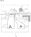
FIG. 3 is a schematic side sectional view illustrating a first aspect of the jet soldering apparatus according to the present embodiment. -
FIG. 4 is a perspective view illustrating an example of a lower cooling unit according to the present embodiment. -
FIG. 5 is a perspective view illustrating an example of an upper cooling unit according to the present embodiment. -
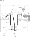
FIG. 6 is a schematic view illustrating a second aspect of the jet soldering apparatus according to the present embodiment. -
FIG. 7 is a schematic view illustrating a third aspect of the jet soldering apparatus according to the present embodiment. -
FIG. 8 is a schematic side sectional view illustrating a fourth aspect of the jet soldering apparatus according to the present embodiment. -
FIG. 9 is an upper plan view illustrating an aspect in which two slit-shaped second openings are provided in the present embodiment. -
FIG. 10 is a schematic side sectional view illustrating a fifth aspect of the jet soldering apparatus according to the present embodiment. -
FIG. 11 is a schematic view illustrating an aspect in which a cooling zone is not installed in the soldering apparatus according to the present embodiment. -
FIG. 12 is a schematic side sectional view illustrating an aspect in which an upper main body of the upper cooling unit and a lower main body of the lower cooling unit are replaceable. -
FIG. 13 is a schematic side sectional view illustrating an aspect in which the upper main body of the upper cooling unit is movable in a horizontal direction and a vertical direction, and the lower main body of the lower cooling unit is movable in the horizontal direction and the vertical direction. -
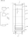
FIG. 14 is a perspective view illustrating a measurement unit, a guide part, and the like, and illustrating that the measurement unit can communicate with a display unit and a notification unit. -
FIG. 15A is an enlarged perspective view of the measurement unit. -
FIG. 15B is an enlarged perspective view of the measurement unit, and is a perspective view illustrating a side opposite toFIG. 15A . -
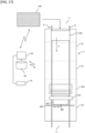
FIG. 16 is a schematic side sectional view illustrating an aspect in which the guide part and the display unit are installed. -
FIG. 17 is an upper plan view illustrating the soldering apparatus in which the measurement unit and the guide part are installed. - A soldering apparatus illustrated in
FIG. 1 is an apparatus that performs soldering processing on asubstrate 200 on which electronic components such as semiconductor elements, resistors, and capacitors are mounted on a circuit. Typically, the electronic components and the like are positioned on a lower side of thesubstrate 200. The soldering apparatus has amain body 1 and aconveyance unit 5 that conveys thesubstrate 200. Themain body 1 has a carry-inport 2 through which thesubstrate 200 is carried in and a carry-outport 3 through which thesubstrate 200 is carried out. Thesubstrate 200 may be conveyed at a predetermined angle, for example, an inclination of about 3 to 6 degrees when viewed from the side (seeFIG. 3 ). In this case, a downstream side is positioned at a higher position than an upstream side in a substrate conveyance direction A. However, the present invention is not limited thereto, and thesubstrate 200 may be horizontally conveyed, for example. Theconveyance unit 5 may have a conveyance driver (not illustrated) that applies a driving force, and aconveyance rail 6 that guides thesubstrate 200. As theconveyance rail 6, aluminum, iron, stainless steel, or the like may be used. - As illustrated in
FIG. 1 , themain body 1 may be provided with afluxer 10 for applying flux to thesubstrate 200, apreheater unit 15 for preheating thesubstrate 200 coated with flux, ajet soldering apparatus 100 for jetting molten solder into contact with thesubstrate 200, and a cooler 20 for cooling the solderedsubstrate 200. Thesubstrate 200 conveyed along theconveyance rail 6 of theconveyance unit 5 sequentially passes through thefluxer 10, thepreheater unit 15, thejet soldering apparatus 100, and the cooler 20. A part where the cooler 20 is provided is a cooling zone. However, as will be described later, in the present embodiment, cooling units such as anupper cooling unit 310 and alower cooling unit 330 are provided. Therefore, as illustrated inFIG. 11 , the cooling zone may not be provided without installing the cooler 20. Thejet soldering apparatus 100 may have acontrol unit 50 that gives a command to each component to control, and astorage unit 60 that stores various pieces of information. Note that inFIG. 1 , the soldering apparatus is illustrated in an upper plan view except for thecontrol unit 50, thestorage unit 60, and anoperation unit 70 described later. - The
fluxer 10 is used to apply flux to the conveyedsubstrate 200. The flux may include a solvent, an activator, and the like. Thefluxer 10 may be provided with a plurality of coating apparatuses. The type of flux may be selectively used according to the type of solder and the type of thesubstrate 200. - The
preheater unit 15 heats thesubstrate 200 to uniformly raise thesubstrate 200 to a predetermined temperature. When thesubstrate 200 is heated in this manner, the solder is easily attached to a predetermined part of thesubstrate 200. For example, a halogen heater is used as thepreheater unit 15. The halogen heater can rapidly heat thesubstrate 200 to a set temperature. Furthermore. Thesubstrate 200 may be heated by blowing gas (hot air) heated by the heater onto thesubstrate 200 by a fan. Furthermore, as thepreheater unit 15, a far-infrared panel heater or the like may be used. - The cooler 20 has a cooling fan which is not illustrated, and cools the
substrate 200 soldered by thejet soldering apparatus 100. The control of the cooling fan may be only ON and OFF, but the wind speed may be adjusted. Furthermore, as the cooler 20, a chiller or the like may be used to cool thesubstrate 200 to a predetermined temperature. - The
control unit 50 illustrated inFIG. 1 is communicably connected to theconveyance unit 5 including theconveyance rail 6, thefluxer 10, thepreheater unit 15, thejet soldering apparatus 100, the cooler 20, theoperation unit 70, and thestorage unit 60. The communicable connections include both wired and wireless connections. Theoperation unit 70 may have a liquid crystal display panel, a numeric keypad, or the like, and is typically a personal computer, a smartphone, a tablet, a touch panel or the like. When an operator operates theoperation unit 70, thecontrol unit 50 may control a conveyance speed by theconveyance unit 5, a timing of conveying thesubstrate 200, a temperature of the flux at thefluxer 10, an application amount of the flux, a temperature of thepreheater unit 15, a temperature of molten solder S of thejet soldering apparatus 100, a jet amount, a jet speed, ON and OFF of the cooling fan of the cooler 20, and the like. Thestorage unit 60 may store information input by theoperation unit 70, an instruction of thecontrol unit 50, an operating time of thejet soldering apparatus 100, and the like. The conveyance speed of thesubstrate 200 is about 1 to 3 cm per second. - Next, the
jet soldering apparatus 100 of the present embodiment will be described. - As illustrated in
FIG. 3 , thejet soldering apparatus 100 may have astorage tank 110 that stores molten solder S, a supply port for supplying the molten solder S to thesubstrate 200, and a cooling unit that is positioned on the downstream side (right side inFIG. 3 ) of the supply port in the conveyance direction of thesubstrate 200, is provided at an upper position of thestorage tank 110, and includes thelower cooling unit 330 and/or theupper cooling unit 310 that supplies gas for cooling the solder supplied to thesubstrate 200 and attached to thesubstrate 200. The supply port may have two types of afirst supply port 125 and asecond supply port 135. Then, molten solder S may be jetted from thefirst supply port 125 by receiving a driving force from afirst pump 141 that is a first drive unit, and molten solder S may be jetted from asecond supply port 135 by receiving a driving force from asecond pump 146 that is a second drive unit. - The molten solder S jetted from the
first supply port 125 and thesecond supply port 135 is jetted upward from below. The molten solder S having received the driving force from thefirst pump 141 is pressure-fed in a duct and jetted toward thesubstrate 200 to attach the solder to a predetermined part of thesubstrate 200. Similarly, the molten solder S having received the driving force from thesecond pump 146 is pressure-fed in a duct and jetted toward thesubstrate 200 to attach the solder to a predetermined part of thesubstrate 200. The molten solder S is heated to a temperature of, for example, about 160° C. to 260° C. by a heater which is not illustrated. The molten solder supplied from thefirst supply port 125 and thesecond supply port 135 may be circulated and used. In this case, it may be circulated through a filter which is not illustrated. Each of thefirst pump 141 and thesecond pump 146 is typically constituted of one pump, but each of thefirst pump 141 and thesecond pump 146 may be constituted of a plurality of pumps. - The
first supply port 125 of thejet soldering apparatus 100 illustrated inFIGS. 2 and3 has a plurality offirst openings 126, and thefirst openings 126 constitute a primary jet nozzle. The plurality offirst openings 126 are used to vigorously supply a large amount of molten solder S to thesubstrate 200. Asecond opening 136 of thesecond supply port 135 is a secondary jet nozzle, and is used to supply the molten solder S to thesubstrate 200 with weaker force than thefirst supply port 125. The jet solder supplied from thefirst supply port 125 is a dynamic supply for vigorously colliding the molten solder S against thesubstrate 200, and is a supply for spreading the molten solder S to every corner of thesubstrate 200. On the other hand, the jet solder supplied from thesecond supply port 135 is a static supply, and is a supply for cleanly attaching the solder to an electrode or the like of thesubstrate 200 by passing the jet solder through the molten solder S having a gentle flow. The configuration of the jet soldering apparatus and conditions such as a force of the jet of the molten solder are examples, and the present application is not limited to the above configuration. - As illustrated in
FIG. 3 , afirst supply unit 120 has afirst housing 121 and thefirst supply port 125 provided on an upper surface of thefirst housing 121 and having one or the plurality offirst openings 126 for supplying the molten solder S. Thefirst opening 126 may be provided so as to protrude upward from the upper surface of thefirst housing 121. Asecond supply unit 130 has asecond housing 131 and thesecond supply port 135 provided on an upper surface of thesecond housing 131 and having one or a plurality of thesecond openings 136 for supplying the molten solder S. Thefirst housing 121 and thesecond housing 131 may be provided apart from each other (seeFIG. 3 ), but they may be provided integrally (seeFIGS. 6 and7 ). In a case where thefirst housing 121 and thesecond housing 131 are integrated, a part of the wall surface may be shared. In the present embodiment, thefirst supply port 125 having the plurality of circularfirst openings 126 and thesecond supply port 135 having one slit-shapedsecond opening 136 will be described as an example. However, the present invention is not limited to such an aspect, and for example, a plurality of the slit-shapedsecond openings 136 may be provided. In this case, the plurality of slit-shapedsecond openings 136 may be provided in an aspect of extending in parallel (seeFIG. 9 ). - A temperature of the molten solder S is generally a melting temperature of the solder +30°C. In recent years, there has been an increasing need to lower a working temperature in order to reduce damage to components and reduce mechanical power consumption. In addition, since the market price of Sn and Ag has soared, it has been examined to use solder that does not use Sn and Ag, and typically, it has been examined to use Sn-58Bi (a solder alloy including Bi: 58% by mass and Sn as a balance. Melting point: 139°C, tensile strength: 76.5 MPs, and elongation: 27%) instead of SAC305 (a solder alloy including: Ag: 3% by mass, Cu: 0.5% by mass, and Sn as a balance. Melting point: 217°C, tensile strength: 53.3 MPs, and elongation: 46%). Sn-58Bi is a low-temperature eutectic solder. Note that, when Sn-58Bi is used, soldering can be performed at a temperature of 200° C. or lower. On the other hand, since Sn-58Bi has a property of being hard and brittle, it is a material difficult to handle.
- While the molten solder S is supplied, the molten solder S supplied from the
first supply port 125 and the molten solder S supplied from thesecond supply port 135 are mixed. The molten solder mixed in this manner may not be separated from thesubstrate 200 conveyed by theconveyance unit 5 between thefirst supply port 125 and the second supply port 135 (seeFIGS. 6 and7 ). By adopting such a configuration, it is possible to prevent the molten solder S from being oxidized (generation of oxidized waste). As a result, an amount of solder that becomes unavailable can be suppressed, and material cost can be reduced. - The
substrate 200 is supported and conveyed by theconveyance rail 6, but an upper surface of the mixed molten solder S may not be positioned below a lower end of theconveyance rail 6 that conveys thesubstrate 200 when viewed from a side in an entire length region along the substrate conveyance direction A between thefirst supply port 125 and thesecond supply port 135. In the present embodiment, "between thefirst supply port 125 and thesecond supply port 135" means between a downstream end in the substrate conveyance direction A of thefirst supply port 125 and an upstream end in the substrate conveyance direction A of the second supply port 135 (see "G" inFIGS. 2 and3 ). Note that inFIGS. 6 and7 , the components other than thefirst pump 141 and thesecond pump 146 are illustrated as cross-sectional views when viewed from the side. - The width Z2 of the installation region of the
second supply port 135 along the substrate conveyance direction A may be narrower than the width Z1 of the installation region of thefirst supply port 125 along the substrate conveyance direction A. When such an aspect is adopted, the amount of molten solder S supplied from thesecond supply port 135 can be easily made smaller than the amount of molten solder S supplied from thefirst supply port 125. As a result, a plurality of waves (convex shapes) of the molten solder S supplied from thefirst supply port 125 can be prevented from being crushed by the molten solder S supplied from thesecond supply port 135, and both dynamic supply of the molten solder S from thefirst supply port 125 and static supply of the molten solder S from thesecond supply port 135 can be provided in a well-balanced manner. As illustrated inFIG. 7 , when the width Z2 of the installation region of thesecond supply port 135 along the substrate conveyance direction A is large, it is necessary to perform adjustment so that the amount of the molten solder S to be supplied does not become too large, and at the same time, it is necessary to perform adjustment so that thesubstrate 200 continues to be in contact with the molten solder S between thesecond supply port 135 and thefirst supply port 125, and thus the adjustment is difficult. From this viewpoint, it is advantageous to adopt an aspect in which the width Z2 of the installation region of thesecond supply port 135 along the substrate conveyance direction A is smaller than the width Z1 of the installation region of thefirst supply port 125 along the substrate conveyance direction A. - The total amount of molten solder S per unit time supplied from the
first openings 126 and the total amount of molten solder S per unit time supplied from thesecond opening 136 which is the secondary jet nozzle may be changed according to the type of thesubstrate 200. When identification information of thesubstrate 200 is input from theoperation unit 70, a supply amount of the corresponding molten solder S may be read from thestorage unit 60 by thecontrol unit 50, and the molten solder S may be supplied from thefirst openings 126 and thesecond opening 136 by being adjusted to the read supply amount. Theoperation unit 70 may be capable of reading code information such as a bar code, and thecontrol unit 50 may automatically adjust the supply amount of the molten solder S to thesubstrate 200 by reading the code information of thesubstrate 200. - The molten solder S supplied from the
first openings 126 which are the primary jet nozzle may be jetted to a position higher than a surface of the molten solder S supplied from thesecond opening 136 which is the secondary jet nozzle. A height of the molten solder S to be jetted is, for example, about 10 mm from a tip of each of thefirst openings 126. The molten solder S supplied from thesecond supply port 135 is pushed up by the molten solder S supplied from thefirst supply port 125. However, since the molten solder S is the same type of liquid, the molten solder S supplied from thefirst openings 126 and the molten solder S supplied from thesecond supply port 135 are mixed. - On a downstream side of the
second supply port 135 in the substrate conveyance direction A, a downstream adjustingpart 182 extending in a horizontal direction or descending downward toward the downstream side may be provided (seeFIG. 3 ). A height of the downstream adjustingpart 182 may be appropriately changed. An upstream adjustingpart 181 extending in the horizontal direction or rising upward toward the downstream side may be provided on an upstream side of thefirst supply port 125 in the substrate conveyance direction A. Theupstream adjusting part 181 and the downstream adjustingpart 182 may be linearly inclined, or may be inclined so as to draw an arc in a longitudinal cross section (seeFIG. 6 ). A height adjustment of the upstream adjustingpart 181 and the downstream adjustingpart 182 may be manually performed, or may be automatically performed in response to a command from thecontrol unit 50. The command from thecontrol unit 50 may be issued on the basis of the identification information of thesubstrate 200. Adjusting the heights of the upstream adjustingpart 181 and the downstream adjustingpart 182 as described above is also advantageous in that the amount of the molten solder S supplied to thesubstrate 200 can be adjusted. - A height position of the
conveyance rail 6 may also be adjustable (seeFIG. 3 ). In a case where such an aspect is adopted, adjusting the height position of theconveyance rail 6 in addition to or instead of controlling the driving force of thefirst pump 141 and thesecond pump 146 is also advantageous in that it is possible to realize a configuration in which thesubstrate 200 continues to be in contact with the molten solder S between thefirst supply port 125 and thesecond supply port 135. The height position of theconveyance rail 6 may be manually performed, or may be automatically performed in response to a command from thecontrol unit 50. The command from thecontrol unit 50 may be issued on the basis of the identification information of thesubstrate 200. - A distance G between the
first supply port 125 and thesecond supply port 135 along the extending direction of the conveyance rail 6 (along the substrate conveyance direction A) may be smaller than the width Z1 of the installation region of thefirst supply port 125 along the substrate conveyance direction A. When such an aspect is adopted, the distance between thefirst supply port 125 and thesecond supply port 135 can be shortened. Therefore, it is advantageous in that it is possible to realize an aspect in which the molten solder S is not separated from thesubstrate 200 conveyed by theconveyance unit 5 between thefirst supply port 125 and thesecond supply port 135 while reducing the amount of the molten solder S supplied from thesecond supply port 135. - The distance G between the
first supply port 125 and thesecond supply port 135 along the extending direction of theconveyance rail 6 extends may be smaller than the width Z2 of the installation region of thesecond supply port 135 along the substrate conveyance direction A (distance along the extending direction of the conveyance rail 6). In the present embodiment, as an example, it is assumed that the width Z2 of the installation region of thesecond supply port 135 along the substrate conveyance direction A is smaller than the width Z1 of the installation region of thefirst supply port 125 along the substrate conveyance direction A (seeFIGS. 3 and6 ). Therefore, in a case where this aspect is adopted, the distance between thefirst supply port 125 and thesecond supply port 135 can be considerably close (seeFIG. 8 ). When such an aspect is adopted, the distance between thefirst supply port 125 and thesecond supply port 135 can be further shortened. Therefore, it is advantageous in that it is possible to realize an aspect in which the molten solder S is not separated from thesubstrate 200 conveyed by theconveyance unit 5 between thefirst supply port 125 and thesecond supply port 135 while further reducing the amount of the molten solder S supplied from thesecond supply port 135. - The cooling unit may have a
lower cooling unit 330 positioned at a position lower than theconveyance rail 6 of thesubstrate 200 and above thestorage tank 110, and anupper cooling unit 310 provided at a position higher than theconveyance rail 6 and an upper position of thestorage tank 110. In the present application, "provided at an upper position of thestorage tank 110" means that when a straight line is drawn in an upward direction (vertical direction) from an end part of thestorage tank 110 to divide the region, at least a part exists in a region α divided by the straight line. Therefore, the fact that thelower cooling unit 330 is provided at the upper position of thestorage tank 110 means that at least a part of thelower cooling unit 330 exists in the region α when the straight line is drawn in the upward direction (vertical direction) from thestorage tank 110 to divide the region. Similarly, the fact that theupper cooling unit 310 is provided at the upper position of thestorage tank 110 means that at least a part of theupper cooling unit 310 exists in the region α when the straight line is drawn in the upward direction (vertical direction) from thestorage tank 110 to divide the region. - Note that the
lower cooling unit 330 directly cools the solder attached to thesubstrate 200, which is large from the viewpoint of a cooling effect. Therefore, when only one of theupper cooling unit 310 and thelower cooling unit 330 is to be installed, installing thelower cooling unit 330 is considered as a first candidate. - In the configuration in the related art, the
substrate 200 receives heat from the molten solder S accumulated in thestorage tank 110. However, by providing thelower cooling unit 330 at the upper position of thestorage tank 110 as in the present embodiment, it is advantageous in that the solder can be cooled by the gas supplied from thelower cooling unit 330 while blocking the influence of the heat from the molten solder S. - By providing the
lower cooling unit 330 and theupper cooling unit 310 positioned on the upper side of thestorage tank 110, the solder can be cooled immediately after the molten solder S is supplied to the substrate 200 (after two to five seconds as an example), and the solder can be cured. Therefore, it is possible to prevent a decrease in strength of the solder (embrittlement of the solder). In particular, in a case of low-temperature molten solder having a low melting point such as Sn-58Bi, this effect is considerably large. When it takes time to cure the solder, vibration is applied during conveyance in a soft state where the solder is not completely cured, but it is considered that the vibration causes embrittlement of the solder. Incidentally, it takes ten seconds or more to reach the cooling zone existing in the related art, but the present embodiment is different in that the curing of the solder can be started in a considerably shorter time than the time. In the present embodiment, the low-temperature molten solder means solder having a melting point of 180°C or lower. - By providing the
lower cooling unit 330 and/or theupper cooling unit 310 at positions on the downstream side of thefirst supply port 125 and thesecond supply port 135 in the conveyance direction of the substrate 200 (a position on the right side in the aspect illustrated inFIG. 3 ) instead of providing the cooling unit at positions where the supply ports such as thefirst supply port 125 and thesecond supply port 135 are provided, it is possible to prevent the molten solder S being supplied from thefirst supply port 125 and thesecond supply port 135 from being cooled. - The
upper cooling unit 310 and/or thelower cooling unit 330 may have a slit-shaped opening for supplying gas, or may have a plurality of small-diameter openings. The wind speed of the gas supplied from theupper cooling unit 310 and/or thelower cooling unit 330 may be about several meters to several tens of meters per second. Theupper cooling unit 310 and thelower cooling unit 330 may supply air at a room temperature as the gas. By providing both thelower cooling unit 330 and theupper cooling unit 310, it is possible to quickly cool thesubstrate 200 from above and below, and it is possible to more reliably prevent a decrease in strength of the solder (embrittlement of the solder). In addition, in a case where air at a normal temperature is supplied as gas, it is advantageous in that air having a temperature considerably lower than the melting temperature of the solder can be supplied to thesubstrate 200. In addition, by supplying air instead of nitrogen or the like, it is not necessary to adopt a sealed structure required for supplying nitrogen or the like, and it is advantageous in that the apparatus configuration is simplified and manufacturing can be performed at low cost. In addition, since heat easily accumulates in the sealed structure, it is advantageous to have an open type apparatus configuration also from this viewpoint. In addition, when nitrogen is supplied, splashing of the molten solder tends to increase, but such splashing can be prevented by adopting air. When nitrogen is used, energy for operating the apparatus can be reduced, and the apparatus can be made carbon neutral. The air supplied from theupper cooling unit 310 and/or thelower cooling unit 330 may be cooled by a cooling mechanism such as a chiller, or the outside air may be supplied as it is without providing a cooling mechanism. When the cooling mechanism is not provided, energy used in the apparatus can be reduced. - The
upper cooling unit 310 may have an uppermain body 311 extending orthogonal to the substrate conveyance direction, and anupper supply port 315 provided on a side surface of the uppermain body 311 and jetting and supplying gas such as air (seeFIG. 5 ). Theupper supply port 315 may be a linear slit as illustrated inFIG. 5 , but may be provided with a plurality of small openings or protruding nozzles (seeFIGS. 6 and7 ). The uppermain body 311 may extend across the pair ofconveyance rails 6 as illustrated inFIG. 9 , or may extend between the pair ofconveyance rails 6 as illustrated inFIG. 2 . By providing such anupper cooling unit 310, theentire substrate 200 can be quickly cooled. In particular, when theupper supply port 315 is a linear slit, thesubstrate 200 can be cooled more uniformly from above. When a nozzle is adopted as theupper supply port 315, a gas supply direction can be determined, the solder can be prevented from being cooled while the solder is being attached to thesubstrate 200, and the occurrence of solder icicles can be more reliably prevented. - The
lower cooling unit 330 may have a lowermain body 331 andlower supply ports conveyance rail 6 of thesubstrate 200 and jetting and supplying gas such as air (seeFIGS. 2 ,4 , and9 ). Thelower supply ports lower cooling unit 330, thesubstrate 200 can be directly cooled from the side to which the molten solder is attached, and high cooling efficiency can be realized. Even when a nozzle is adopted as thelower supply ports substrate 200, and the occurrence of solder icicles can be more reliably prevented. - In the aspect illustrated in
FIGS. 2 and9 , the slit-shaped firstlower supply port 335a and the secondlower supply port 335b including a plurality of nozzles are provided. The firstlower supply port 335a has an effect of cooling the solder on the surface and mainly has a function of cooling and curing the solder. In this case, the firstlower supply port 335a functions as a first cooling unit for cooling the solder. On the other hand, the secondlower supply port 335b including a plurality of nozzles mainly has a function of cooling thesubstrate 200, and exerts the effect performed in the cooling zone in the related art. In this case, the secondlower supply port 335b functions as a second cooling unit for cooling thesubstrate 200. Adopting such an aspect is advantageous in that the substrate can be cooled by the secondlower supply port 335b while the solder is quickly cured by the firstlower supply port 335a. - The first
lower supply port 335a may be provided with areturn part 333 that faces the downstream side in the substrate conveyance direction A and allows the gas supplied from the firstlower supply port 335a to flow toward the downstream side in the substrate conveyance direction A (seeFIG. 4 ). By adopting such an aspect, it is possible to more reliably prevent the gas such as air supplied from the firstlower supply port 335a from being supplied while the solder is being attached to thesubstrate 200. In the aspects illustrated inFIGS. 2 and9 , thereturn part 333 is not illustrated, but in a case where thereturn part 333 is provided inFIGS. 2 and9 , thereturn part 333 is installed so as to cover the entire upper portion of the firstlower supply port 335a. - The
upper supply port 315 may also have a slit-shaped firstupper supply port 315a and a secondupper supply port 315b including a plurality of nozzles (seeFIG. 6 ). The firstupper supply port 315a has an effect of cooling the solder on the surface, and may mainly have a function of cooling and curing the solder. In this case, the firstupper supply port 315a functions as a first cooling unit for cooling the solder. On the other hand, the secondupper supply port 315b including a plurality of nozzles mainly has a function of cooling thesubstrate 200, and may exhibit the effect performed in the cooling zone in the related art. In this case, the secondupper supply port 315b functions as a second cooling unit for cooling thesubstrate 200. The firstupper supply port 315a may also be provided with a return part (not illustrated) that faces the downstream side in the substrate conveyance direction A and allows the gas supplied from the firstupper supply port 315a to flow toward the downstream side in the substrate conveyance direction A. - From the viewpoint of cooling and curing the solder, only the first
lower supply port 335a and the firstupper supply port 315a may be provided, and the secondlower supply port 335b and the secondupper supply port 315b may not be provided (seeFIG. 7 ). - Each of the entire
upper supply port 315 and the entirelower supply port 335 may be positioned in the region α that is the upper position of thestorage tank 110. When the secondupper supply port 315b and the secondlower supply port 335b are provided, each of the entire firstupper supply port 315a and the entire firstlower supply port 335a may be positioned in the region α that is the upper position of thestorage tank 110, and at least a part of the secondupper supply port 315b and the secondlower supply port 335b may be positioned in the region α that is the upper position of thestorage tank 110. - The
lower cooling unit 330 may be positioned on the downstream side of theupper cooling unit 310 in the conveyance direction of thesubstrate 200. When thelower cooling unit 330 is too close to thesecond supply port 135, there is a possibility that thelower cooling unit 330 may be covered with the molten solder S supplied from thefirst supply port 125 and thesecond supply port 135, and thus, it is not possible to install thelower cooling unit 330 considerably close to thesecond supply port 135. On the other hand, since there is a low possibility that theupper cooling unit 310 is covered with the molten solder S supplied from thefirst supply port 125 and thesecond supply port 135, theupper cooling unit 310 can be installed close to thesecond supply port 135 when viewed along the conveyance direction of thesubstrate 200. Therefore, by adopting an aspect in which thelower cooling unit 330 is positioned on the downstream side of theupper cooling unit 310 in the conveyance direction of thesubstrate 200, while gas is supplied from theupper cooling unit 310 immediately after solder is attached to thesubstrate 200, gas can be supplied from a position where thelower cooling unit 330 is not covered with the molten solder S. The fact that thelower cooling unit 330 is positioned on the downstream side of theupper cooling unit 310 in the conveyance direction of thesubstrate 200 means that an upstream end part (left end inFIG. 3 ) of theupper cooling unit 310 is positioned on the upstream side (left side inFIG. 3 ) of the upstream end part (left end inFIG. 3 ) of thelower cooling unit 330. - The cooling unit may supply gas so that the gas flows along the direction in which the
substrate 200 is conveyed. As an example, theupper supply port 315 of theupper cooling unit 310 may be installed so as to jet gas from obliquely above thesubstrate 200 toward the downstream side of the conveyance direction of thesubstrate 200. By adopting such an aspect, it is possible to prevent the temperature of the molten solder from lowering while it is being attached to thesubstrate 200. When the temperature of the molten solder rapidly decreases while the molten solder is being attached to thesubstrate 200, the molten solder may be hardened before the molten solder is rounded by surface tension, and thus solder icicles may occur. In this regard, in the present aspect, it is possible to prevent the formation of such solder icicles. In particular, in the present embodiment, the cooling unit is provided on thestorage tank 110, and the molten solder is cooled at a position extremely close to an area where the molten solder is attached to thesubstrate 200. Therefore, it is necessary to avoid a temperature decrease in a region where thesubstrate 200 is attached to the molten solder, and it is advantageous to adopt an aspect in which gas is jetted from obliquely above thesubstrate 200 toward the downstream side of the conveyance direction of thesubstrate 200 as in the present aspect. In addition, as described above, in a case where theupper cooling unit 310 is positioned on the upstream side of thelower cooling unit 330 in the conveyance direction of thesubstrate 200, it is advantageous that theupper supply port 315 is installed so as to jet gas from obliquely above thesubstrate 200 toward the downstream side of the conveyance direction of thesubstrate 200 in order to prevent gas such as air supplied from theupper cooling unit 310 from being blown to the molten solder while the molten solder is being attached to thesubstrate 200. - For the same reason, the
lower supply ports lower cooling unit 330 may also be installed so as to jet gas from obliquely below thesubstrate 200 toward the downstream side of the conveyance direction of thesubstrate 200. However, such an aspect may not be adopted in a case where thelower cooling unit 330 is positioned on the downstream side of theupper cooling unit 310 in the conveyance direction of thesubstrate 200, and thelower cooling unit 330 is farther from the area where the molten solder is attached to thesubstrate 200 than theupper cooling unit 310. That is, theupper supply port 315 of theupper cooling unit 310 is installed so as to jet gas from obliquely above thesubstrate 200 toward the downstream side of the conveyance direction of thesubstrate 200, but thelower supply ports lower cooling unit 330 may be installed so as to jet gas in the vertical direction with respect to the substrate 200 (seeFIG. 10 ). - In order to jet gas toward the downstream side of the conveyance direction of the
substrate 200 in this manner, the above-described return part 333 (the return part that can be installed in theupper cooling unit 310 is not illustrated) may be used. - An aspect may be adopted in which no opening or gap through which the molten solder S falls downward is provided between the
first supply port 125 and thesecond supply port 135 on an upper surface of thefirst housing 121 and thesecond housing 131 along the substrate conveyance direction A. When an opening or a gap through which the molten solder S falls downward is provided, a surface area where the molten solder S comes into contact with oxygen increases, and an oxide is generated. On the other hand, in a case of adopting an aspect in which a part where the molten solder S falls, such as an opening or a gap, is not provided between thefirst supply port 125 and thesecond supply port 135 along the substrate conveyance direction A as in the present aspect, the molten solder S does not fall between thefirst supply port 125 and thesecond supply port 135 along the substrate conveyance direction A, so that generation of an oxide of the molten solder S can be prevented. In addition, in a case where the opening or the gap through which the molten solder S falls downward is not provided, the region where the molten solder S is supplied to thesubstrate 200 can be shortened, and as a result, it is also advantageous in that the timing of starting the cooling of the solder by theupper cooling unit 310 and thelower cooling unit 330 on thestorage tank 110 can be advanced. - Next, an example of a processing method of a
substrate 200 will be described mainly with reference toFIG. 11 . - When an operator places the
substrate 200 on theconveyance rail 6, theconveyance unit 5 conveys thesubstrate 200, and thesubstrate 200 is conveyed into themain body 1 from the carry-inport 2. When thesubstrate 200 reaches thefluxer 10, thefluxer 10 applies flux to a predetermined part of thesubstrate 200. - The
conveyance unit 5 conveys thesubstrate 200 coated with the flux by thefluxer 10 to thepreheater unit 15. Thepreheater unit 15 heats thesubstrate 200 to a predetermined temperature. - Next, the
conveyance unit 5 conveys thesubstrate 200 heated to the predetermined temperature by the preheater unit to thejet soldering apparatus 100. Thejet soldering apparatus 100 solders a predetermined part of thesubstrate 200. While thejet soldering apparatus 100 is supplying the molten solder S, the molten solder S supplied from thefirst supply port 125 and the molten solder S supplied from thesecond supply port 135 are mixed, and the molten solder S is supplied to above theconveyance rail 6. As an example, the molten solder S is configured not to be separated from thesubstrate 200 conveyed by theconveyance unit 5 between thefirst supply port 125 and thesecond supply port 135. Note that in a state where thesubstrate 200 does not exist, the molten solder S supplied from thefirst supply port 125 pushes up the molten solder S supplied from thesecond supply port 135, and a plurality of convex shapes corresponding to thefirst openings 126 are formed by the molten solder S. - In this way, immediately after the molten solder S is supplied to the substrate 200 (after three to five seconds as an example), gas such as air is supplied to the
substrate 200 from each of theupper cooling unit 310 and thelower cooling unit 330, and the solder is cured. In this way, since the solder is cured immediately after the molten solder S is supplied to thesubstrate 200, the embrittlement of the solder can be prevented from occurring. - Thereafter, when the
conveyance unit 5 discharges thesubstrate 200 from a carry-outport 3, the soldering processing to thesubstrate 200 is completed. In the aspect in which the cooling zone is provided, cooling by the cooler 20 is performed after cooling by the gas supplied from each of theupper cooling unit 310 and thelower cooling unit 330, and thereafter, thesubstrate 200 is discharged from the carry-out port 3 (seeFIG. 1 ). - As a modified example, as shown in
FIG. 10 , onepump 140 may be provided, and the amount of molten solder S flowing into afirst passage 161 connected to thefirst supply port 125 and the amount of molten solder S flowing into asecond passage 162 connected to thesecond supply port 135 may be adjustable. The amount of the molten solder S flowing into thefirst passage 161 may be adjusted by afirst adjustment valve 166, and the amount of the molten solder S flowing into thesecond passage 162 may be adjusted by asecond adjustment valve 167. The amount of the molten solder S flowing into thefirst passage 161 and the amount of the molten solder S flowing into thesecond passage 162 may be adjusted by a relative ratio between an opening degree of thefirst adjustment valve 166 and an opening degree of thesecond adjustment valve 167. In a case where this aspect is adopted, the amount of the molten solder S supplied from thefirst supply port 125 and the amount of the molten solder S supplied from thesecond supply port 135 can be adjusted while using only onepump 140. The opening degrees of thefirst adjustment valve 166 and thesecond adjustment valve 167 may be automatically adjusted in response to a command from thecontrol unit 50 based on the information read from thestorage unit 60 on the basis of the identification information of thesubstrate 200 input by the operation unit 70 (seeFIG. 1 andFIG. 11 ) or read by theoperation unit 70. - However, since it is difficult to adjust the amount of the molten solder S using only one
pump 140 to a certain extent, in the generaljet soldering apparatus 100 in which many types ofsubstrates 200 have to be treated in one day, it is advantageous that the amount of the molten solder S supplied from thefirst supply port 125 and thesecond supply port 135 can be adjusted using two or more pumps as described above. - As another aspect, sizes of the inlets of the
first passage 161 and thesecond passage 162 may be appropriately adjusted while using only onepump 140. In this case, by manually or automatically adjusting the sizes of the inlets of thefirst passage 161 and thesecond passage 162, the amount of the molten solder S supplied from thefirst supply port 125 and the amount of the molten solder S supplied from thesecond supply port 135 can be adjusted. - A plurality of the
pumps 140 may also be provided also in this modified example. Also in this case, the amount of the molten solder S supplied from thefirst supply port 125 and the amount of the molten solder S supplied from thesecond supply port 135 may be adjustable by adjusting the opening degrees of thefirst adjustment valve 166 and thesecond adjustment valve 167 and the sizes of the inlets of thefirst passage 161 and thesecond passage 162. - One or both of the
upper cooling unit 310 and thelower cooling unit 330 may be of a replacement type, and the size or the like thereof may be changed by replacement (seeFIG. 12 ). By adopting such an aspect, the positions of theupper supply port 315 and thelower supply ports upper cooling unit 310 and thelower cooling unit 330 may be movable along the horizontal direction (seeFIG. 13 ). Wind directions of theupper cooling unit 310 and thelower cooling unit 330 may be changed. For example, the wind direction from theupper cooling unit 310 may be changeable by theupper cooling unit 310 being rotatable along an axis extending in a direction orthogonal to the substrate conveyance direction A in the horizontal direction. Further, the wind direction from thelower cooling unit 330 may be changeable by changing the direction of the protruding nozzle of thelower cooling unit 330. By adopting such an aspect, the positions of theupper supply port 315 and thelower supply ports lower cooling unit 330, the positions of thelower supply ports upper cooling unit 310 and thelower cooling unit 330 may be movable also in the vertical direction. In the present application, "along the horizontal direction" may be any direction including a component in the horizontal direction, and includes an aspect of moving along an oblique direction with respect to the horizontal direction. Similarly, "along the vertical direction" may be any direction including a component in the vertical direction, and also includes an aspect of moving along an oblique direction with respect to the vertical direction. - A
measurement unit 400 that measures the temperature of thesubstrate 200 after being cooled by theupper cooling unit 310 and thelower cooling unit 330 may be provided (seeFIGS. 14 to 17 ). By measuring the temperature of thesubstrate 200 conveyed by themeasurement unit 400 in this manner, it is possible to check and manage whether or not solder curing or cooling immediately after soldering for achieving the solder curing is appropriately performed. In a case of an aspect in which the cooler 20 is installed, themeasurement unit 400 may be installed at a position before thesubstrate 200 is cooled by the cooler 20. As an example, themeasurement unit 400 may be installed immediately downstream side of thelower cooling unit 330 in the substrate conveyance direction A (seeFIGS. 16 and17 ). Here, "immediately downstream side in the substrate conveyance direction A" means a region within 30 cm from a downstream end part of the member positioned on the downstream side in the substrate conveyance direction A, of theupper cooling unit 310 and thelower cooling unit 330. Themeasurement unit 400 may be, for example, a thermometer sensor. - A
display unit 410 that displays the temperature of thesubstrate 200 measured by themeasurement unit 400 may be provided (seeFIGS. 14 and16 ). Thedisplay unit 410 may be, for example, a thermometer display. By providing such adisplay unit 410, the operator can easily check the temperature of thesubstrate 200. - As an example, the temperature of the cooled
substrate 200 on the soldering surface side (lower side) is measured by themeasurement unit 400 installed on the downstream side of theupper cooling unit 310 and thelower cooling unit 330 in the substrate conveyance direction A. Then, a temperature measurement result is transmitted to a thermometer amplifier 405 (seeFIG. 14 ). Then, thethermometer amplifier 405 transmits the temperature measurement result to thedisplay unit 410, and the temperature measurement result is displayed on thedisplay unit 410. However, the present invention is not limited to such an aspect, and the measurement result by themeasurement unit 400 may be directly transmitted to thedisplay unit 410, and the measurement result may be displayed on thedisplay unit 410. Note that the function of thethermometer amplifier 405 is typically to convert a measurement signal of themeasurement unit 400 into a signal that can be understood by thedisplay unit 410. Therefore, in a case where the signal that can be understood by thedisplay unit 410 can be transmitted from themeasurement unit 400 to thedisplay unit 410, it is not particularly necessary to install thethermometer amplifier 405. - The
measurement unit 400 may be attached to aguide part 440 including a slide rail or the like extending in the horizontal direction, in a direction orthogonal to the substrate conveyance direction A (seeFIGS. 14 and15A ). In this case, themeasurement unit 400 is movable along theguide part 440. Further, angle adjustment and vertical height adjustment of themeasurement unit 400 with respect to theguide part 440 may be possible (seeFIG. 15B ). In addition, the position of theguide part 440, which includes a slide rail or the like, in the vertical direction may be changeable. Further, the position of theguide part 440 along the substrate conveyance direction A may be changeable. -
FIGS. 14 ,15A, and 15B illustrate an example. In the aspect illustrated inFIG. 14 , a pair of first verticaladjustment adjusting bolts 460 are illustrated, and by loosening the first verticaladjustment adjusting bolts 460, theguide part 440 becomes movable in the vertical direction along a verticallylong guide hole 470a provided in avertical extension portion 470, and by tightening the first verticaladjustment adjusting bolts 460, the position of theguide part 440 in the vertical direction with respect to thevertical extension portion 470 is fixed. In the aspect illustrated inFIG. 15A , aknurling knob 441 is illustrated, and by loosening theknurling knob 441, a measurementunit fixing member 443 to which themeasurement unit 400 is attached can move along theguide part 440, and by tightening theknurling knob 441, the position of the measurementunit fixing member 443 in the horizontal direction with respect to theguide part 440 is fixed. In the aspect illustrated inFIG. 15B , a second verticaladjustment adjusting bolt 442 is illustrated, and by loosening the second verticaladjustment adjusting bolt 442, the measurementunit fixing member 443 becomes movable in the vertical direction (movable with respect to the guide part 440) in a form of being guided by a verticallylong guide hole 443a provided in the measurementunit fixing member 443, and the position of the measurementunit fixing member 443 with respect to theguide part 440 in the vertical direction is fixed by tightening the second verticaladjustment adjusting bolt 442. - When the temperature of the substrate measured by the
measurement unit 400 is out of a predetermined temperature range, thecontrol unit 50 may transmit a signal such as a control signal for stopping the carry-in of thesubstrate 200 to an external device 500 (seeFIG. 17 ) positioned on the upstream side of thejet soldering apparatus 100 such as a component mounting device. When such an aspect is adopted, in a case where there is a high possibility that the solder curing or the cooling immediately after the soldering for achieving the solder curing is not appropriately performed, it is possible to forcibly stop thesubstrate 200 from being carried in from theexternal device 500 positioned on the upstream side of thejet soldering apparatus 100. The predetermined temperature range may be input from theoperation unit 70 or may be read from information stored in thestorage unit 60. - When the temperature of the substrate measured by the
measurement unit 400 is out of the predetermined temperature range, anotification unit 430 such as an alarm device that notifies that the temperature of thesubstrate 200 is out of the predetermined temperature range may be provided (seeFIG. 14 ). When such an aspect is adopted, in a case where there is a high possibility that the solder curing or the cooling immediately after the soldering for achieving the solder curing is not appropriately performed, it is possible to notify the operator or the like of the fact. Information may be transmitted to thenotification unit 430 directly from themeasurement unit 400 or via thethermometer amplifier 405 or the like. Note that thedisplay unit 410 may function as the notification unit. In this case, thedisplay unit 410 may display a warning when the temperature of thesubstrate 200 is out of the predetermined temperature range. - The above description of any embodiments including the modified example and the disclosure of the drawings are merely examples for describing the invention defined in the claims, and the invention defined in the claims is not limited by the above description of the embodiment and the disclosure of the drawings. In addition, the description of the claims at the time of filing is only an example, and the description of the claims can be changed as appropriate based on the description of the description, drawings, and the like.
-
- 6
- conveyance rail
- 100
- jet soldering apparatus
- 110
- storage tank
- 121
- first housing
- 125
- first supply port
- 131
- second housing
- 135
- second supply port
- 200
- substrate
- 310
- upper cooling unit
- 330
- lower cooling unit
- S
- molten solder
Claims (12)
- A jet soldering apparatus comprising:a storage tank configured to store molten solder;a supply port for supplying the molten solder to a substrate; anda cooling unit that is positioned on a downstream side of the supply port in a conveyance direction of the substrate, is provided at an upper position of the storage tank, and is configured to supply gas.
- The jet soldering apparatus according to claim 1,
wherein the cooling unit has a lower cooling unit configured to supply the gas from below to the substrate conveyed, and an upper cooling unit configured to supply the gas from upper to the substrate conveyed. - The jet soldering apparatus according to claim 2,
wherein the lower cooling unit is positioned on a downstream side of the upper cooling unit in the conveyance direction of the substrate. - The jet soldering apparatus according to claim 1 or 2,
wherein the cooling unit supplies the gas toward a downstream side of the conveyance direction of the substrate. - The jet soldering apparatus according to claim 4,wherein the cooling unit has a lower cooling unit configured to supply the gas from below to the substrate conveyed, and an upper cooling unit configured to supply the gas from upper to the substrate conveyed,wherein the upper cooling unit supplies the gas toward obliquely downward along the conveyance direction of the substrate, andwherein the lower cooling unit supplies the gas toward obliquely upward along the conveyance direction of the substrate.
- The jet soldering apparatus according to claim 1 or 2,
wherein the cooling unit has a first cooling unit for cooling the solder supplied to the substrate, and a second cooling unit for cooling the substrate. - The jet soldering apparatus according to claim 1 or 2,
wherein the cooling unit supplies air at a room temperature as the gas. - The jet soldering apparatus according to claim 1 or 2,wherein the supply port has a first supply port for supplying the molten solder provided at a first housing, and a second supply port for supplying the molten solder provided at a second housing, andwherein a part where the molten solder falls is not provided between the first supply port and the second supply port along the conveyance direction of the substrate.
- The jet soldering apparatus according to claim 1 or 2 comprising a measurement unit that measures a temperature of the substrate after being cooled by the cooling unit.
- The jet soldering apparatus according to claim 9 comprising a display unit that displays the temperature of the substrate measured by the measurement unit.
- The jet soldering apparatus according to claim 9,
wherein when the temperature of the substrate measured by the measurement unit is out of a predetermined temperature range, a signal is transmitted for stopping a carry-in of the substrate. - The jet soldering apparatus according to claim 9 comprising a notification unit that notifies that the temperature of the substrate is out of a predetermined temperature range when the temperature of the substrate measured by the measurement unit is out of the predetermined temperature range.
Applications Claiming Priority (3)
| Application Number | Priority Date | Filing Date | Title |
|---|---|---|---|
| JP2022094828 | 2022-06-13 | ||
| JP2023008559 | 2023-01-24 | ||
| PCT/JP2023/021647 WO2023243575A1 (en) | 2022-06-13 | 2023-06-12 | Jet flow soldering device |
Publications (2)
| Publication Number | Publication Date |
|---|---|
| EP4535935A1 true EP4535935A1 (en) | 2025-04-09 |
| EP4535935A4 EP4535935A4 (en) | 2025-10-15 |
Family
ID=89191271
Family Applications (1)
| Application Number | Title | Priority Date | Filing Date |
|---|---|---|---|
| EP23823865.3A Pending EP4535935A4 (en) | 2022-06-13 | 2023-06-12 | JET FLOW SOLDERING DEVICE |
Country Status (9)
| Country | Link |
|---|---|
| US (1) | US20250375827A1 (en) |
| EP (1) | EP4535935A4 (en) |
| JP (1) | JP7530031B2 (en) |
| KR (1) | KR102899407B1 (en) |
| CN (1) | CN119384872A (en) |
| MX (1) | MX2024015110A (en) |
| MY (1) | MY210057A (en) |
| TW (1) | TWI871663B (en) |
| WO (1) | WO2023243575A1 (en) |
Family Cites Families (21)
| Publication number | Priority date | Publication date | Assignee | Title |
|---|---|---|---|---|
| DE2932398C2 (en) * | 1979-08-09 | 1981-10-15 | Siemens AG, 1000 Berlin und 8000 München | Device for cooling printed circuit boards after electrical components have been soldered in by machine |
| JPS61137669A (en) * | 1984-12-11 | 1986-06-25 | Tamura Seisakusho Co Ltd | Jet type soldering device |
| US5685475A (en) * | 1995-09-08 | 1997-11-11 | Ford Motor Company | Apparatus for cooling printed circuit boards in wave soldering |
| JP3398538B2 (en) * | 1995-12-28 | 2003-04-21 | 日本電熱計器株式会社 | Method of collecting process data in soldering equipment |
| JP2000244108A (en) * | 1999-02-22 | 2000-09-08 | Senju Metal Ind Co Ltd | Soldering of printed board, soldering equipment for printed board, and cooling equipment therefor |
| JP2000340938A (en) * | 1999-05-27 | 2000-12-08 | Nihon Dennetsu Keiki Co Ltd | Soldering method and soldering device |
| JP4332281B2 (en) * | 2000-04-26 | 2009-09-16 | 株式会社日立製作所 | Electronic device manufacturing method and soldering apparatus |
| JP2002043734A (en) * | 2000-07-24 | 2002-02-08 | Senju Metal Ind Co Ltd | Method and apparatus for soldering printed circuit board |
| JP3491199B2 (en) | 2000-10-05 | 2004-01-26 | ミネベア株式会社 | Circuit board cooling device |
| JP2002329956A (en) * | 2001-04-27 | 2002-11-15 | Ricoh Co Ltd | Soldering method, electronic circuit board manufactured using the soldering method, and electronic equipment |
| JP2004022709A (en) * | 2002-06-14 | 2004-01-22 | Senju Metal Ind Co Ltd | Soldering method and automatic soldering equipment of printed board |
| JP2004111472A (en) * | 2002-09-13 | 2004-04-08 | Ryusyo Industrial Co Ltd | Flow soldering method and flow soldering apparatus |
| JP4186635B2 (en) * | 2003-01-30 | 2008-11-26 | ソニー株式会社 | Solder cooling method, solder cooling device, and solder reflow device |
| JP2005294671A (en) | 2004-04-02 | 2005-10-20 | Vantec Inc | Soldered PCB cooling device |
| JP2007258487A (en) | 2006-03-23 | 2007-10-04 | Espec Corp | Soldering device cooling device and soldering device |
| US8403199B2 (en) * | 2009-03-24 | 2013-03-26 | Senju Metal Industry Co., Ltd. | Localized jet soldering device and partial jet soldering method |
| JP5526957B2 (en) | 2010-04-09 | 2014-06-18 | 千住金属工業株式会社 | Soldering equipment |
| JP2011222786A (en) * | 2010-04-09 | 2011-11-04 | Senju Metal Ind Co Ltd | Jet soldering device and method for controlling inert gas supply |
| CN102485396A (en) * | 2010-12-03 | 2012-06-06 | 西安中科麦特电子技术设备有限公司 | Energy-saving wave crest welder |
| CN102485400A (en) * | 2010-12-06 | 2012-06-06 | 西安中科麦特电子技术设备有限公司 | Crest welder cooling device |
| JP2020163403A (en) * | 2019-03-28 | 2020-10-08 | 太陽誘電株式会社 | Manufacturing method of thermocompression bonding equipment and electronic parts |
-
2023
- 2023-06-12 US US18/874,549 patent/US20250375827A1/en active Pending
- 2023-06-12 KR KR1020257000635A patent/KR102899407B1/en active Active
- 2023-06-12 JP JP2024528827A patent/JP7530031B2/en active Active
- 2023-06-12 CN CN202380043408.4A patent/CN119384872A/en active Pending
- 2023-06-12 MY MYPI2024007059A patent/MY210057A/en unknown
- 2023-06-12 WO PCT/JP2023/021647 patent/WO2023243575A1/en not_active Ceased
- 2023-06-12 EP EP23823865.3A patent/EP4535935A4/en active Pending
- 2023-06-13 TW TW112122004A patent/TWI871663B/en active
-
2024
- 2024-12-05 MX MX2024015110A patent/MX2024015110A/en unknown
Also Published As
| Publication number | Publication date |
|---|---|
| JP7530031B2 (en) | 2024-08-07 |
| EP4535935A4 (en) | 2025-10-15 |
| TW202406653A (en) | 2024-02-16 |
| MY210057A (en) | 2025-08-23 |
| KR102899407B1 (en) | 2025-12-12 |
| KR20250019145A (en) | 2025-02-07 |
| MX2024015110A (en) | 2025-01-09 |
| US20250375827A1 (en) | 2025-12-11 |
| JPWO2023243575A1 (en) | 2023-12-21 |
| WO2023243575A1 (en) | 2023-12-21 |
| TWI871663B (en) | 2025-02-01 |
| CN119384872A (en) | 2025-01-28 |
Similar Documents
| Publication | Publication Date | Title |
|---|---|---|
| US6168065B1 (en) | Movable selective debridging apparatus for debridging soldered joints on printed circuit boards | |
| US20250256342A1 (en) | Method of processing substrate using jet soldering apparatus | |
| US11130188B2 (en) | Jet solder bath and jet soldering device | |
| EP3437775B1 (en) | Jet solder bath and jet soldering apparatus | |
| KR101591633B1 (en) | Device for coating thin molten solder film, thin solder film-covered component and manufacturing method therefor | |
| US7442037B2 (en) | Reflow Furnace | |
| US20100243718A1 (en) | Selective soldering apparatus with jet wave solder jet and nitrogen preheat | |
| US20250375827A1 (en) | Jet soldering apparatus | |
| JP2007067061A (en) | Flux recovery device | |
| US20010030220A1 (en) | Apparatus and methods for wave soldering | |
| JPS61126962A (en) | Apparatus for generating wave of solder | |
| EP4275823B1 (en) | Solder processing device | |
| JP2011035086A (en) | Jet soldering apparatus | |
| JP2006156487A (en) | Reflow furnace nitrogen gas consumption reduction apparatus and method | |
| EP4535936A1 (en) | Jet soldering device | |
| JP2019114718A (en) | Jet solder tank and jet soldering device | |
| CN106304684A (en) | A kind of selection welds carrier and welding method thereof | |
| JP2009123796A (en) | Reflow heating apparatus | |
| JP2006261417A (en) | Flow soldering equipment | |
| JPH07214298A (en) | Jet soldering equipment | |
| JP2013251332A (en) | External cooling chamber of reflow solder device and reflow solder facility |
Legal Events
| Date | Code | Title | Description |
|---|---|---|---|
| STAA | Information on the status of an ep patent application or granted ep patent |
Free format text: STATUS: THE INTERNATIONAL PUBLICATION HAS BEEN MADE |
|
| PUAI | Public reference made under article 153(3) epc to a published international application that has entered the european phase |
Free format text: ORIGINAL CODE: 0009012 |
|
| STAA | Information on the status of an ep patent application or granted ep patent |
Free format text: STATUS: REQUEST FOR EXAMINATION WAS MADE |
|
| 17P | Request for examination filed |
Effective date: 20241231 |
|
| AK | Designated contracting states |
Kind code of ref document: A1 Designated state(s): AL AT BE BG CH CY CZ DE DK EE ES FI FR GB GR HR HU IE IS IT LI LT LU LV MC ME MK MT NL NO PL PT RO RS SE SI SK SM TR |
|
| DAV | Request for validation of the european patent (deleted) | ||
| DAX | Request for extension of the european patent (deleted) | ||
| A4 | Supplementary search report drawn up and despatched |
Effective date: 20250916 |
|
| RIC1 | Information provided on ipc code assigned before grant |
Ipc: H05K 3/34 20060101AFI20250910BHEP Ipc: B23K 1/08 20060101ALI20250910BHEP Ipc: B23K 3/08 20060101ALI20250910BHEP |
|
| GRAP | Despatch of communication of intention to grant a patent |
Free format text: ORIGINAL CODE: EPIDOSNIGR1 |
|
| STAA | Information on the status of an ep patent application or granted ep patent |
Free format text: STATUS: GRANT OF PATENT IS INTENDED |
|
| INTG | Intention to grant announced |
Effective date: 20260227 |
|
| GRAS | Grant fee paid |
Free format text: ORIGINAL CODE: EPIDOSNIGR3 |
|
| GRAA | (expected) grant |
Free format text: ORIGINAL CODE: 0009210 |
|
| STAA | Information on the status of an ep patent application or granted ep patent |
Free format text: STATUS: THE PATENT HAS BEEN GRANTED |