EP4535898A1 - Verfahren und vorrichtung zur steuerung des betriebsmodus für erweiterte bandbreite in einem wlan-system - Google Patents
Verfahren und vorrichtung zur steuerung des betriebsmodus für erweiterte bandbreite in einem wlan-system Download PDFInfo
- Publication number
- EP4535898A1 EP4535898A1 EP23816380.2A EP23816380A EP4535898A1 EP 4535898 A1 EP4535898 A1 EP 4535898A1 EP 23816380 A EP23816380 A EP 23816380A EP 4535898 A1 EP4535898 A1 EP 4535898A1
- Authority
- EP
- European Patent Office
- Prior art keywords
- subfield
- mhz
- control
- information
- frame
- Prior art date
- Legal status (The legal status is an assumption and is not a legal conclusion. Google has not performed a legal analysis and makes no representation as to the accuracy of the status listed.)
- Pending
Links
Images


Classifications
-
- H—ELECTRICITY
- H04—ELECTRIC COMMUNICATION TECHNIQUE
- H04W—WIRELESS COMMUNICATION NETWORKS
- H04W72/00—Local resource management
- H04W72/20—Control channels or signalling for resource management
-
- H—ELECTRICITY
- H04—ELECTRIC COMMUNICATION TECHNIQUE
- H04L—TRANSMISSION OF DIGITAL INFORMATION, e.g. TELEGRAPHIC COMMUNICATION
- H04L5/00—Arrangements affording multiple use of the transmission path
- H04L5/003—Arrangements for allocating sub-channels of the transmission path
- H04L5/0053—Allocation of signalling, i.e. of overhead other than pilot signals
-
- H—ELECTRICITY
- H04—ELECTRIC COMMUNICATION TECHNIQUE
- H04L—TRANSMISSION OF DIGITAL INFORMATION, e.g. TELEGRAPHIC COMMUNICATION
- H04L5/00—Arrangements affording multiple use of the transmission path
- H04L5/0001—Arrangements for dividing the transmission path
- H04L5/0014—Three-dimensional division
- H04L5/0023—Time-frequency-space
-
- H—ELECTRICITY
- H04—ELECTRIC COMMUNICATION TECHNIQUE
- H04W—WIRELESS COMMUNICATION NETWORKS
- H04W72/00—Local resource management
- H04W72/50—Allocation or scheduling criteria for wireless resources
- H04W72/53—Allocation or scheduling criteria for wireless resources based on regulatory allocation policies
-
- H—ELECTRICITY
- H04—ELECTRIC COMMUNICATION TECHNIQUE
- H04W—WIRELESS COMMUNICATION NETWORKS
- H04W74/00—Wireless channel access
- H04W74/002—Transmission of channel access control information
- H04W74/006—Transmission of channel access control information in the downlink, i.e. towards the terminal
-
- H—ELECTRICITY
- H04—ELECTRIC COMMUNICATION TECHNIQUE
- H04W—WIRELESS COMMUNICATION NETWORKS
- H04W84/00—Network topologies
- H04W84/02—Hierarchically pre-organised networks, e.g. paging networks, cellular networks, WLAN [Wireless Local Area Network] or WLL [Wireless Local Loop]
- H04W84/10—Small scale networks; Flat hierarchical networks
- H04W84/12—WLAN [Wireless Local Area Networks]
-
- H—ELECTRICITY
- H04—ELECTRIC COMMUNICATION TECHNIQUE
- H04L—TRANSMISSION OF DIGITAL INFORMATION, e.g. TELEGRAPHIC COMMUNICATION
- H04L27/00—Modulated-carrier systems
- H04L27/26—Systems using multi-frequency codes
-
- H—ELECTRICITY
- H04—ELECTRIC COMMUNICATION TECHNIQUE
- H04L—TRANSMISSION OF DIGITAL INFORMATION, e.g. TELEGRAPHIC COMMUNICATION
- H04L5/00—Arrangements affording multiple use of the transmission path
-
- H—ELECTRICITY
- H04—ELECTRIC COMMUNICATION TECHNIQUE
- H04L—TRANSMISSION OF DIGITAL INFORMATION, e.g. TELEGRAPHIC COMMUNICATION
- H04L5/00—Arrangements affording multiple use of the transmission path
- H04L5/0091—Signalling for the administration of the divided path, e.g. signalling of configuration information
- H04L5/0094—Indication of how sub-channels of the path are allocated
-
- H—ELECTRICITY
- H04—ELECTRIC COMMUNICATION TECHNIQUE
- H04W—WIRELESS COMMUNICATION NETWORKS
- H04W72/00—Local resource management
- H04W72/04—Wireless resource allocation
- H04W72/044—Wireless resource allocation based on the type of the allocated resource
- H04W72/0453—Resources in frequency domain, e.g. a carrier in FDMA
-
- H—ELECTRICITY
- H04—ELECTRIC COMMUNICATION TECHNIQUE
- H04W—WIRELESS COMMUNICATION NETWORKS
- H04W74/00—Wireless channel access
- H04W74/08—Non-scheduled access, e.g. ALOHA
-
- H—ELECTRICITY
- H04—ELECTRIC COMMUNICATION TECHNIQUE
- H04W—WIRELESS COMMUNICATION NETWORKS
- H04W80/00—Wireless network protocols or protocol adaptations to wireless operation
Definitions
- the present disclosure relates to a method and device for indicating an operating mode for extended bandwidth in a Wireless Local Area Network (WLAN) system.
- WLAN Wireless Local Area Network
- Wi-Fi Wireless LAN
- technologies recently introduced to WLAN include enhancements for Very High-Throughput (VHT) of the 802.11ac standard, and enhancements for High Efficiency (HE) of the IEEE 802.11ax standard.
- VHT Very High-Throughput
- HE High Efficiency
- the technical object of the present disclosure is to provide a method and device for indicating information for an extended bandwidth when indicating an operation mode.
- a method performed by a station (STA) in a wireless LAN system may comprise: generating a frame including information for an indication of an operating channel width; and transmitting a PPDU including the frame.
- the information for the indication of the operating channel width may be included in an operating mode (OM) control subfield in an aggregated-control (A-control) field of the frame, and the OM control subfield may include a specific subfield indicatable a wide bandwidth greater than 320 MHz.
- the STA3 may set a NAV timer for a frame transmission period (e.g., SIFS + CTS frame + SIFS + data frame + SIFS + ACK frame) that is continuously transmitted thereafter, using the duration information included in the RTS frame.
- a NAV timer for a frame transmission period (e.g., SIFS + data frame + SIFS + ACK frame) that is continuously transmitted thereafter, using the duration information included in the CTS frame.
- FIG. 6 is a diagram for explaining an example of a frame structure used in a WLAN system to which the present disclosure may be applied.
- a PHY layer protocol data unit (PPDU) frame format is defined.
- PPDU frame format e.g., HT-mixed format PPDU, HT-greenfield format PPDU, VHT (Very High Throughput) PPDU, etc.
- STF, LTF, and SIG fields may be included between the SIG field and the data field (this will be described later with reference to FIG. 7 ).
- the SIG field may include a RATE field and a LENGTH field.
- the RATE field may include information on modulation and coding rates of data.
- the LENGTH field may include information on the length of data. Additionally, the SIG field may include a parity bit, a SIG TAIL bit, and the like.
- a MAC PDU is defined according to various MAC frame formats, and a basic MAC frame consists of a MAC header, a frame body, and a Frame Check Sequence (FCS).
- the MAC frame may consist of MAC PDUs and be transmitted/received through the PSDU of the data part of the PPDU frame format.
- the MAC header includes a Frame Control field, a Duration/ID field, an Address field, and the like.
- the frame control field may include control information required for frame transmission/reception.
- the duration/ID field may be set to a time for transmitting a corresponding frame or the like.
- FIG. 7 is a diagram illustrating examples of PPDUs defined in the IEEE 802.11 standard to which the present disclosure may be applied.
- the basic PPDU format (IEEE 802.11a/g) includes L-LTF, L-STF, L-SIG and Data fields.
- the basic PPDU format may also be referred to as a non-HT PPDU format.
- the HT PPDU format (IEEE 802.11n) additionally includes HT-SIG, HT-STF, and HT-LFT(s) fields to the basic PPDU format.
- the HT PPDU format shown in FIG. 7 may be referred to as an HT-mixed format.
- an HT-greenfield format PPDU may be defined, and this corresponds to a format consisting of HT-GF-STF, HT-LTF1, HT-SIG, one or more HT-LTF, and Data field, not including L-STF, L-LTF, and L-SIG (not shown).
- VHT PPDU format (IEEE 802.11ac) additionally includes VHT SIG-A, VHT-STF, VHT-LTF, and VHT-SIG-B fields to the basic PPDU format.
- HE PPDU format (IEEE 802.11ax) additionally includes Repeated L-SIG (RL-SIG), HE-SIG-A, HE-SIG-B, HE-STF, HE-LTF(s), Packet Extension (PE) field to the basic PPDU format.
- R-SIG Repeated L-SIG
- HE-SIG-A HE-SIG-B
- HE-STF HE-LTF(s)
- PE Packet Extension
- Some fields may be excluded or their length may vary according to detailed examples of the HE PPDU format.
- the HE-SIG-B field is included in the HE PPDU format for multi-user (MU), and the HE-SIG-B is not included in the HE PPDU format for single user (SU).
- SU single user
- the HE trigger-based (TB) PPDU format does not include the HE-SIG-B, and the length of the HE-STF field may vary to 8 us.
- the Extended Range (HE ER) SU PPDU format does not include the HE-SIG-B field, and the length of the HE-SIG-A field may vary to 16us.
- FIGs. 8 to 10 are diagrams for explaining examples of resource units of a WLAN system to which the present disclosure may be applied.
- the RU may include a plurality of subcarriers (or tones).
- the RU may be used when transmitting signals to multiple STAs based on the OFDMA scheme.
- the RU may be defined even when a signal is transmitted to one STA.
- the RU may be used for STF, LTF, data field of the PPDU, etc.
- RUs corresponding to different numbers of tones are used to construct some fields of 20 MHz, 40 MHz, or 80 MHz X-PPDUs (X is HE, EHT, etc.).
- X is HE, EHT, etc.
- resources may be allocated in RU units shown for the X-STF, X-LTF, and Data field.
- FIG. 8 is a diagram illustrating an exemplary allocation of resource units (RUs) used on a 20 MHz band.
- 26-units i.e., units corresponding to 26 tones
- 6 tones may be used as a guard band in the leftmost band of the 20 MHz band
- 5 tones may be used as a guard band in the rightmost band of the 20 MHz band.
- 7 DC tones are inserted in the center band, that is, the DC band
- 26-units corresponding to each of the 13 tones may exist on the left and right sides of the DC band.
- 26-unit, 52-unit, and 106-unit may be allocated to other bands. Each unit may be allocated for STAs or users.
- the RU allocation of FIG. 8 is utilized not only in a situation for multiple users (MU) but also in a situation for a single user (SU), and in this case, it is possible to use one 242-unit as shown at the bottom of FIG. 8 . In this case, three DC tones may be inserted.
- RUs of various sizes that is, 26-RU, 52-RU, 106-RU, 242-RU, etc. are exemplified, but the specific size of these RUs may be reduced or expanded. Therefore, in the present disclosure, the specific size of each RU (i.e., the number of corresponding tones) is exemplary and not restrictive. In addition, within a predetermined bandwidth (e.g., 20, 40, 80, 160, 320 MHz, ...) in the present disclosure, the number of RUs may vary according to the size of the RU. In the examples of FIG. 9 and/or FIG. 10 to be described below, the fact that the size and/or number of RUs may be varied is the same as the example of FIG. 8 .
- FIG. 9 is a diagram illustrating an exemplary allocation of resource units (RUs) used on a 40 MHz band.
- a 484-RU when used for a single user, a 484-RU may be used.
- FIG. 10 is a diagram illustrating an exemplary allocation of resource units (RUs) used on an 80 MHz band.
- the STA transmitting the DL MU PPDU may allocate a first RU (e.g., 26/52/106/242-RU, etc.) to a first STA and allocate a second RU (e.g., 26/52/106/242-RU, etc.) to a second STA. That is, the transmitting STA (e.g., AP) may transmit HE-STF, HE-LTF, and Data field for the first STA through the first RU and transmit HE-STF, HE-LTF, and Data field for the second STA through the second RU, in one MU PPDU,
- a first RU e.g., 26/52/106/242-RU, etc.
- a second RU e.g., 26/52/106/242-RU, etc.
- the HE-SIG-B field may include a common field and a user-specific field. If HE-SIG-B compression is applied (e.g., full-bandwidth MU-MIMO transmission), the common field may not be included in HE-SIG-B, and the HE-SIG-B content channel may include only a user-specific field. If HE-SIG-B compression is not applied, the common field may be included in HE-SIG-B.
- one user/STA may be allocated to each of a plurality of RUs, and different users/STAs may be allocated to different RUs.
- a predetermined size e.g., 106, 242, 484, 996-tones, (7)
- a plurality of users/STAs may be allocated to one RU, and MU-MIMO scheme may be applied for the plurality of users/STAs.
- the user field may be constructed based on two formats.
- the user field for a MU-MIMO allocation may be constructed with a first format
- the user field for non-MU-MIMO allocation may be constructed with a second format.
- user fields 1 to 3 may be based on the first format
- user fields 4 to 8 may be based on the second format.
- the first format and the second format may contain bit information of the same length (e.g., 21 bits).
- the user field of the first format (i.e., format for MU-MIMO allocation) may be constructed as follows. For example, out of all 21 bits of one user field, B0-B10 includes the user's identification information (e.g., STA-ID, AID, partial AID, etc.), B11-14 includes spatial configuration information such as the number of spatial streams for the corresponding user, B15-B18 includes Modulation and Coding Scheme (MCS) information applied to the Data field of the corresponding PPDU, B19 is defined as a reserved field, and B20 may include information on a coding type (e.g., binary convolutional coding (BCC) or low-density parity check (LDPC)) applied to the Data field of the corresponding PPDU.
- BCC binary convolutional coding
- LDPC low-density parity check
- FIG. 13 illustrates an example of a PPDU format to which the present disclosure may be applied.
- the PPDU of FIG. 13 may be referred as various names such as an EHT PPDU, a transmitted PPDU, a received PPDU, a first type or an Nth type PPDU.
- the PPDU or EHT PPDU of the present disclosure may be referred as various names such as a transmission PPDU, a reception PPDU, a first type or an Nth type PPDU.
- the EHT PPU may be used in an EHT system and/or a new wireless LAN system in which the EHT system is improved.
- the EHT MU PPDU of FIG. 13 corresponds to a PPDU carrying one or more data (or PSDUs) for one or more users. That is, the EHT MU PPDU may be used for both SU transmission and MU transmission.
- the EHT MU PPDU may correspond to a PPDU for one receiving STA or a plurality of receiving STAs.
- the EHT-SIG is omitted compared to the EHT MU PPDU.
- the STA may perform UL transmission based on the EHT TB PPDU format.
- L-STF to EHT-LTF correspond to a preamble or a physical preamble, and may be generated/transmitted/received/acquired/decoded in the physical layer .
- the tone/subcarrier index of L-STF, L-LTF, L-SIG, RL-SIG, U-SIG, and EHT-SIG field may be indicated in units of 312.5 kHz
- the tone/subcarrier index of EHT-STF, EHT-LTF, Data, and PE field may be indicated in units of 78.125 kHz.
- the L-LTF and L-STF of FIG. 13 may be constructed identically to the corresponding fields of the PPDU described in FIGS. 6 to 7 .
- the L-SIG field of FIG. 13 may be constructed with 24 bits and may be used to communicate rate and length information.
- the L-SIG field includes a 4-bit Rate field, a 1-bit Reserved bit, a 12-bit Length field, a 1-bit Parity field, and a 6-bit Tail field may be included.
- the 12-bit Length field may include information on a time duration or a length of the PPDU.
- a value of the 12-bit Length field may be determined based on the type of PPDU. For example, for a non-HT, HT, VHT, or EHT PPDU, the value of the Length field may be determined as a multiple of 3. For example, for the HE PPDU, the value of the Length field may be determined as a multiple of 3 + 1 or a multiple of 3 + 2.
- the transmitting STA may apply BCC encoding based on a coding rate of 1/2 to 24-bit information of the L-SIG field. Thereafter, the transmitting STA may obtain 48-bit BCC coded bits. BPSK modulation may be applied to 48-bit coded bits to generate 48 BPSK symbols. The transmitting STA may map 48 BPSK symbols to any location except for a pilot subcarrier (e,g,, ⁇ subcarrier index -21, -7, +7, +21 ⁇ ) and a DC subcarrier (e.g., ⁇ subcarrier index 0 ⁇ ).
- a pilot subcarrier e,g, ⁇ subcarrier index -21, -7, +7, +21 ⁇
- DC subcarrier e.g., ⁇ subcarrier index 0 ⁇
- 48 BPSK symbols may be mapped to subcarrier indices -26 to -22, -20 to -8, -6 to -1, +1 to +6, +8 to +20, and +22 to +26.
- the transmitting STA may additionally map the signals of ⁇ -1, -1, -1, 1 ⁇ to the subcarrier index ⁇ -28, -27, +27, +28 ⁇ .
- the above signal may be used for channel estimation in the frequency domain corresponding to ⁇ -28, -27, +27, +28 ⁇ .
- the transmitting STA may construct RL-SIG which is constructed identically to L-SIG.
- RL-SIG BPSK modulation is applied.
- the receiving STA may recognize that the received PPDU is a HE PPDU or an EHT PPDU based on the existence of the RL-SIG.
- U-SIG Universal SIG
- the U-SIG may be referred as various names such as a first SIG field, a first SIG, a first type SIG, a control signal, a control signal field, and a first (type) control signal, etc.
- the U-SIG may include N-bit information and may include information for identifying the type of EHT PPDU.
- U-SIG may be configured based on two symbols (e.g., two consecutive OFDM symbols).
- Each symbol (e.g., OFDM symbol) for the U-SIG may have a duration of 4us, and the U-SIG may have a total 8us duration.
- Each symbol of the U-SIG may be used to transmit 26 bit information.
- each symbol of the U-SIG may be transmitted and received based on 52 data tones and 4 pilot tones.
- a bit information (e.g., 52 un-coded bits) may be transmitted
- the first symbol of the U-SIG (e.g., U-SIG-1) may transmit the first X bit information (e.g., 26 un-coded bits) of the total A bit information
- the second symbol of the U-SIG (e.g., U-SIG-2) may transmit the remaining Y-bit information (e.g., 26 un-coded bits) of the total A-bit information.
- the transmitting STA may obtain 26 un-coded bits included in each U-SIG symbol.
- the transmitting STA may generate 52 BPSK symbols allocated to each U-SIG symbol by performing BPSK modulation on the interleaved 52-coded bits.
- One U-SIG symbol may be transmitted based on 56 tones (subcarriers) from subcarrier index -28 to subcarrier index +28, except for DC index 0.
- the 52 BPSK symbols generated by the transmitting STA may be transmitted based on the remaining tones (subcarriers) excluding pilot tones -21, -7, +7, and +21 tones.
- the A bit information (e.g., 52 un-coded bits) transmitted by the U-SIG includes a CRC field (e.g., a 4-bit field) and a tail field (e.g., 6 bit-length field).
- the CRC field and the tail field may be transmitted through the second symbol of the U-SIG.
- the CRC field may be constructed based on 26 bits allocated to the first symbol of U-SIG and 16 bits remaining except for the CRC/tail field in the second symbol, and may be constructed based on a conventional CRC calculation algorithm.
- the tail field may be used to terminate the trellis of the convolution decoder, and for example, the tail field may be set to 0.
- a bit information (e.g., 52 un-coded bits) transmitted by the U-SIG (or U-SIG field) may be divided into version-independent bits and version-independent bits.
- a size of the version-independent bits may be fixed or variable.
- the version-independent bits may be allocated only to the first symbol of U-SIG, or the version-independent bits may be allocated to both the first symbol and the second symbol of U-SIG.
- the version-independent bits and the version-dependent bits may be referred as various names such as a first control bit and a second control bit, etc.
- the version-independent bits of the U-SIG may include a 3-bit physical layer version identifier (PHY version identifier).
- the 3-bit PHY version identifier may include information related to the PHY version of the transmitted/received PPDU.
- the first value of the 3-bit PHY version identifier may indicate that the transmission/reception PPDU is an EHT PPDU.
- the transmitting STA may set the 3-bit PHY version identifier to a first value.
- the receiving STA may determine that the received PPDU is an EHT PPDU based on the PHY version identifier having the first value.
- the version-independent bits of U-SIG may include a 1-bit UL/DL flag field.
- a first value of the 1-bit UL/DL flag field is related to UL communication, and a second value of the UL/DL flag field is related to DL communication.
- the version-independent bits of the U-SIG may include information on the length of a transmission opportunity (TXOP) and information on a BSS color ID.
- TXOP transmission opportunity
- EHT PPDU related to SU mode e.g., EHT PPDU related to MU mode
- EHT PPDU related to TB mode e.g., EHT PPDU related to Extended Range transmission, etc.
- information on the type of EHT PPDU may be included in the version-dependent bits of the U-SIG.
- the U-SIG may include information on 1) a bandwidth field containing information on a bandwidth, 2) a field containing information on a MCS scheme applied to EHT-SIG, 3) an indication field containing information related to whether the DCM technique is applied to the EHT-SIG, 4) a field containing information on the number of symbols used for EHT-SIG, 5) a field containing information on whether EHT-SIG is constructed over all bands, 6) a field containing information on the type of EHT-LTF/STF, and 7) a field indicating the length of EHT-LTF and CP length.
- Preamble puncturing may be applied to the PPDU of FIG. 13 .
- Preamble puncturing may mean transmission of a PPDU for which no signal is present in one or more 20 MHz subchannels among the bandwidth of the PPDU.
- Preamble puncturing may be applied to a PPDU transmitted to one or more users.
- the resolution of preamble puncturing may be 20 MHz for EHT MU PPDUs in OFDMA transmissions with bandwidths greater than 40 MHz and non-OFDMA transmissions with 80 MHz and 160 MHz bandwidths. That is, in the above case, puncturing on a subchannel smaller than 242-tone RU may not be allowed.
- the resolution of preamble puncturing may be 40 MHz. That is, puncturing for a subchannel smaller than 484-tone RU in a 320 MHz bandwidth may not be allowed. In addition, preamble puncturing may not be applied to the primary 20 MHz channel in the EHT MU PPDU.
- information on preamble puncturing may be included in the U-SIG and/or the EHT-SIG.
- the first field of the U-SIG may include information on the contiguous bandwidth of the PPDU
- the second field of the U-SIG may include information on preamble puncturing applied to the PPDU.
- the U-SIG and the EHT-SIG may include information on preamble puncturing based on the following method. If the bandwidth of the PPDU exceeds 80 MHz, the U-SIG may be individually constructed in units of 80 MHz. For example, if the bandwidth of the PPDU is 160 MHz, the PPDU may include a first U-SIG for a first 80 MHz band and a second U-SIG for a second 80 MHz band. In this case, the first field of the first U-SIG includes information on the 160 MHz bandwidth, and the second field of the first U-SIG includes information on preamble puncturing applied to the first 80 MHz band (i.e., information on a preamble puncturing pattern).
- the first field of the second U-SIG includes information on a 160 MHz bandwidth
- the second field of the second U-SIG includes information on preamble puncturing applied to a second 80 MHz band (i.e., information on a preamble puncturing pattern).
- the EHT-SIG following the first U-SIG may include information on preamble puncturing applied to the second 80 MHz band (i.e., information on a preamble puncturing pattern)
- the EHT-SIG following the second U-SIG may include information on preamble puncturing applied to the first 80 MHz band (i.e., information on a preamble puncturing pattern).
- the U-SIG and the EHT-SIG may include information on preamble puncturing based on the following method.
- the U-SIG may include information on preamble puncturing for all bands (i.e., information on a preamble puncturing pattern). That is, EHT-SIG does not include information on preamble puncturing, and only U-SIG may include information on preamble puncturing (ie, information on a preamble puncturing pattern).
- U-SIG may be constructed in units of 20 MHz. For example, if an 80 MHz PPDU is constructed, the U-SIG may be duplicated. That is, the same 4 U-SIGs may be included in the 80 MHz PPDU. PPDUs exceeding 80 MHz bandwidth may include different U-SIGs.
- the EHT-SIG of FIG. 13 may include control information for the receiving STA.
- EHT-SIG may be transmitted through at least one symbol, and one symbol may have a length of 4us.
- Information on the number of symbols used for EHT-SIG may be included in U-SIG.
- the EHT-SIG may include technical features of HE-SIG-B described through FIGS. 11 and 12 .
- EHT-SIG like the example of FIG. 8 , may include a common field and a user-specific field.
- the Common field of the EHT-SIG may be omitted, and the number of user-specific fields may be determined based on the number of users.
- the common field of the EHT-SIG and the user-specific field of the EHT-SIG may be coded separately.
- One user block field included in the user-specific field may contain information for two user fields, but the last user block field included in the user-specific field may contain one or two user fields. That is, one user block field of the EHT-SIG may contain up to two user fields.
- each user field may be related to MU-MIMO allocation or non-MU-MIMO allocation.
- the common field of the EHT-SIG may include a CRC bit and a Tail bit
- the length of the CRC bit may be determined as 4 bits
- the length of the tail bit is determined by 6 bits and may be set to 000000.
- the common field of the EHT-SIG may include RU allocation information.
- RU allocation information may mean information on the location of an RU to which a plurality of users (i.e., a plurality of receiving STAs) are allocated.
- RU allocation information may be configured in units of 9 bits (or N bits).
- a mode in which a common field of EHT-SIG is omitted may be supported.
- the mode in which the common field of the EHT-SIG is omitted may be referred as a compressed mode.
- a plurality of users (i.e., a plurality of receiving STAs) of the EHT PPDU may decode the PPDU (e.g., the data field of the PPDU) based on non-OFDMA. That is, a plurality of users of the EHT PPDU may decode a PPDU (e.g., a data field of the PPDU) received through the same frequency band.
- multiple users of the EHT PPDU may decode the PPDU (e.g., the data field of the PPDU) based on OFDMA. That is, a plurality of users of the EHT PPDU may receive the PPDU (e.g., the data field of the PPDU) through different frequency bands.
- EHT-SIG may be constructed based on various MCS scheme. As described above, information related to the MCS scheme applied to the EHT-SIG may be included in the U-SIG.
- the EHT-SIG may be constructed based on the DCM scheme.
- the DCM scheme may reuse the same signal on two subcarriers to provide an effect similar to frequency diversity, reduce interference, and improve coverage. For example, modulation symbols to which the same modulation scheme is applied may be repeatedly mapped on available tones/subcarriers.
- modulation symbols e.g., BPSK modulation symbols
- first contiguous half tones e.g., 1st to 26th tones
- modulation symbols e.g., BPSK modulation symbols
- the remaining contiguous half tones e.g., 27th to 52nd tones. That is, a modulation symbol mapped to the 1st tone and a modulation symbol mapped to the 27th tone are the same.
- the EHT-STF of FIG. 13 may be used to enhance automatic gain control (AGC) estimation in a MIMO environment or an OFDMA environment.
- the EHT-LTF of FIG. 13 may be used to estimate a channel in a MIMO environment or an OFDMA environment.
- the PPDU (i.e., EHT PPDU) of FIG. 13 may be constructed based on an example of RU allocation of FIGS. 8 to 10 .
- a EHT PPDU transmitted on a 20 MHz band may be constructed based on the RU of FIG. 8 . That is, a RU location of EHT-STF, EHT-LTF, and data field included in the EHT PPDU may be determined as shown in FIG. 8 .
- a EHT PPDU transmitted on a 40 MHz band that is, a 40 MHz EHT PPDU may be constructed based on the RU of FIG. 9 . That is, a RU location of EHT-STF, EHT-LTF, and data field included in the EHT PPDU may be determined as shown in FIG. 9 .
- the EHT PPDU transmitted on the 80 MHz band may be constructed based on the RU of FIG. 10 . That is, a RU location of EHT-STF, EHT-LTF, and data field included in the EHT PPDU may be determined as shown in FIG. 10 .
- the tone-plan for 80 MHz in FIG. 10 may correspond to two repetitions of the tone-plan for 40 MHz in FIG. 9 .
- the tone-plan for 160/240/320 MHz may be configured in the form of repeating the pattern of FIG. 9 or 10 several times.
- the PPDU of FIG. 13 may be identified as an EHT PPDU based on the following method.
- the receiving STA may determine the type of the received PPDU as the EHT PPDU based on the following. For example, when 1) the first symbol after the L-LTF signal of the received PPDU is BPSK, 2) RL-SIG in which the L-SIG of the received PPDU is repeated is detected, and 3) the result of applying the modulo 3 calculation to the value of the Length field of the L-SIG of the received PPDU (i.e., the remainder after dividing by 3) is detected as 0, the received PPDU may be determined as a EHT PPDU.
- the receiving STA may determine the type of the EHT PPDU based on bit information included in symbols subsequent to the RL-SIG of FIG. 13 . In other words, the receiving STA may determine the received PPDU as a EHT PPDU, based on 1) the first symbol after the L-LTF signal, which is BSPK, 2) RL-SIG contiguous to the L-SIG field and identical to the L-SIG, and 3) L-SIG including a Length field in which the result of applying modulo 3 is set to 0.
- the receiving STA may determine the type of the received PPDU as the HE PPDU based on the following. For example, when 1) the first symbol after the L-LTF signal is BPSK, 2) RL-SIG in which L-SIG is repeated is detected, and 3) the result of applying modulo 3 to the length value of L-SIG is detected as 1 or 2, the received PPDU may be determined as a HE PPDU.
- the receiving STA may determine the type of the received PPDU as non-HT, HT, and VHT PPDU based on the following. For example, when 1) the first symbol after the L-LTF signal is BPSK and 2) RL-SIG in which L-SIG is repeated is not detected, the received PPDU may be determined as non-HT, HT, and VHT PPDU.
- the receiving STA when the receiving STA detects an RL-SIG in which the L-SIG is repeated in the received PPDU, it may be determined that the received PPDU is a HE PPDU or an EHT PPDU. In this case, if the rate (6Mbps) check fails, the received PPDU may be determined as a non-HT, HT, or VHT PPDU. If the rate (6Mbps) check and parity check pass, when the result of applying modulo 3 to the Length value of L-SIG is detected as 0, the received PPDU may be determined as an EHT PPDU, and when the result of Length mod 3 is not 0, it may be determined as a HE PPDU.
- the PPDU of FIG. 13 may be used to transmit and receive various types of frames.
- the PPDU of FIG. 13 may be used for (simultaneous) transmission and reception of one or more of a control frame, a management frame, or a data frame.
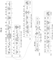
- FIG. 14 is a diagram showing an exemplary format of an A-control subfield of an HT control field to which the present disclosure may be applied.
- the HT Control field may be included in the MAC header.
- the HT Control field may be present in the control wrapper frame and may be present in the QoS Data, QoS Null, and management frames as determined by the +HTC subfield of the frame control field.
- the HT control field may have a format as shown in Table 1.
- Table 1 Variant B0 B1 B2-B29 B30 B31 HT 0 HT Control Middle AC Constraint RDG/More PPDU VHT 1 0 VHT Control Middle AC Constraint RDG/More PPDU HE 1 1 A-Control
- the HE variant HT control field may include an aggregated (A)-control subfield.
- the A-control subfield may have a length of 30 bits.
- the A-control subfield may include a control list subfield of variable length and a padding subfield of zero or more bits.
- the control list subfield may include one or more control subfields.
- the padding subfield may be set to a sequence of zero values such that the length of the A-control subfield included in the HT control field is 30, following the last control subfield (if present).
- a control subfield may include a 4-bit control ID subfield and a variable-length control information subfield.
- the control ID subfield can indicate the type of information included in the control information subfield.
- the length of the control information subfield may be defined as a fixed value for each value of the control ID subfield (excluding reserved values).
- the value of the control ID subfield and the length of the control information subfield associated therewith may be defined as shown in Table 2.
- Control ID value Meaning Length of the Control Information subfield (bits) 0 Triggered response scheduling (TRS) 26 1 Operating mode (OM) 12 2 HE link adaptation (HLA) 26 3 Buffer status report (BSR) 26 4 UL power headroom (UPH) 8 5 Bandwidth query report (BQR) 10 6 Command and status (CAS) 8 7 EHT operating mode (EHT OM) 6 8 Single response scheduling (SRS) 10 9 AP assistance request (AAR) 20 10 -14 Reserved 15 Ones need expansion surely (ONES) 26
- the length of the format (TRS, OM, HLA, BSR, UPH, BQR, CAS, EHT OM, SRS, AAR, etc.) of the control subfield indicated by the control ID value in Table 2 is shown.
- the ONES control subfield may have all 26 bits set to 1.
- the format of each other control subfield is defined separately, and FIG. 14 shows an exemplary format of an OM (operating mode) control subfield having a length of 12 bits.
- the Rx NSS subfield indicates the maximum number (N_SS) of spatial streams supported by the STA in reception for a PPDU bandwidth of 80 MHz or less, and may be set to the value of N_SS-1. If the operating channel of the STA is 80 MHz or less, the Rx NSS subfield indicates the maximum number of spatial streams supported by the STA in reception, N_SS, and may be set to the value of N_SS-1.
- the maximum number of spatial streams supported by the STA in reception for a PPDU bandwidth exceeding 80 MHz may be determined by a given equation considering MCS.
- the Channel Width subfield may indicate the operating channel width supported by the STA for both reception and transmission.
- the value of the Channel Width subfield may be set to 0 for 20 MHz, 1 for primary 40 MHz, 2 for primary 80 MHz, and 3 for 160 MHz or 80+80 MHz.
- a value of 0 in the Channel Width subfield may indicate negotiated 20 MHz when related to subchannel selective transmission (SST) operation, but may indicate primary 20 MHz otherwise.
- the frame type transmitted in response to a triggering frame and the allowed uplink multi-user (UL MU) operations may be determined based on the UL MU Disable subfield, the UL MU Data Disable subfield, and capability elements of the receiver side (e.g., the OM Control UL MU Data Disable Rx Support subfields) (see examples in Table 3). If the OM Control field is transmitted by the AP, the UL MU Disable subfield and the UL MU Data Disable subfield may be reserved.
- Trigger based UL MU transmissions remain enabled by the STA as defined in Transmit operating mode (TOM) indication .
- TOM Transmit operating mode
- a non-AP STA may set the value of the Tx NSTS subfield to N_STS-1, where N_STS is the maximum number of space-time streams that the non-AP STA ssupports in transmission.
- the Tx NSTS subfield may be reserved when the OM Control field is transmitted by the AP.
- a non-AP STA may indicate that 242-tone ER SU PPDU reception is disabled by setting the ER SU Disable subfield to 1, and may indicate that 242-tone ER SU PPDU reception is enabled by setting the value to 0.
- the ER SU Disable subfield may be reserved when the OM Control field is transmitted by the AP.
- a non-AP STA may suggest to the AP a channel resound or an increase in channel sounding frequency with the STA by setting the value of the DL MU-MIMO Resound Recommendation subfield to 1. If the value is set to 0, the STA may indicate to the AP that there is no suggestion for channel sounding frequency. If the OM Control field is transmitted by the AP, the DL MU-MIMO Resound Recommendation subfield may be reserved.
- FIG. 15 is a diagram showing an exemplary format of a control information subfield in an EHT OM Control subfield to which the present disclosure may be applied.
- control information subfield in the EHT OM Control subfield may include information related to OM change for a 320 MHz bandwidth, a Tx NSTS greater than 8, and an Rx NSS greater than 8 for an STA transmitting a frame including OM indication information.
- the Channel Width Extension subfield in the EHT OM Control subfield (e.g., see FIG. 15 ) combined with the Channel Width subfield in the OM control subfield (e.g., see FIG. 14 ) may indicate the operating channel width supported by the STA for both reception and transmission.
- Channel Width Extension subfield in the EHT OM Control subfield (e.g., see FIG. 15 ) combined with the Channel Width subfield in the OM control subfield (e.g., see FIG. 14 ) may be as shown in Table 4.
- Table 4 Channel Width Extension subfield in EHT OM Control subfield Channel Width subfield in OM Control subfield Indication of the operating channel width 0 0 Primary 20 MHz 0 1 Primary 40 MHz 0 2 Primary 80 MHz 0 3 Primary 160 MHz 1 0 320 MHz 1 1-3 Reserved
- an indication for an operating channel width i.e., a BW indication
- a BW indication may be performed using a combination of the Channel Width Extension subfield and the Channel Width subfield.
- signals may be transmitted and received using an extended BW.
- the extended BW may correspond to a 480 MHz bandwidth, a 560 MHz bandwidth, and/or a 640 MHz bandwidth.
- an indication for an extended BW operation may be required to transmit and receive signals for the extended BW.
- a definition of the extended BW in the operation mode (OM) is required.
- a non-legacy STA means an STA that supports a next-generation wireless LAN system, and may correspond to, for example, an STA after an EHT variant (e.g., next wi-fi, UHR, etc.).
- EHT variant e.g., next wi-fi, UHR, etc.
- the extended BW may be configured with the following channel combinations for RU/MRU allocation.
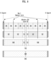
- the 480 MHz bandwidth may be configured with a 320 MHz channel and a 160 MHz channel.
- the 320 MHz channel may be configured as a primary channel.
- the primary channel may mean a 320 MHz channel in a relatively high frequency range within the 480 MHz bandwidth.
- the 480 MHz bandwidth may be configured with three 160 MHz channels.
- the 160 MHz channels may be configured as a primary (or first) 160 MHz channel, a secondary 160 MHz channel, and a third 160 MHz channel (or a 160 MHz channel in a relatively low frequency range within the secondary 320 MHz), respectively.
- the 560 MHz bandwidth may be configured with a 320 MHz channel and a 240 MHz channel.
- the 320 MHz channel may be configured as a primary channel.
- the 560 MHz bandwidth may be configured with three 160 MHz channels and one 80 MHz channel.
- the 160 MHz channels may be expressed as a primary (or first) 160 MHz channel, a secondary 160 MHz channel, and a third 160 MHz channel (or a 160 MHz channel in a relatively low frequency range within the secondary 320 MHz), and the 80 MHz channel may be expressed as a fourth channel, 80 MHz channel in a relatively low frequency range.
- the 640 MHz bandwidth may be composed of a 320 MHz channel and a 320 MHz channel.
- the two 320 MHz channels may be configured as a primary channel and a secondary channel, respectively.
- the secondary channel may mean a 320 MHz channel in a relatively low frequency range within the 640 MHz bandwidth.
- the 640 MHz bandwidth may be composed of four 160 MHz channels.
- the 160 MHz channels may be expressed as a primary (or first) 160 MHz channel, a secondary 160 MHz channel, a third 160 MHz channel, and a fourth 160 MHz channel, respectively.
- the indication for the extended BW may be performed based on at least one of the following embodiments.
- This embodiment relates to a method for performing an extended BW instruction for a non-legacy STA using an existing OM Control. This embodiment is described by considering a case where the existing OM Control corresponds to the EHT OM Control field described above.
- the OM Control field for the next generation wireless LAN system does not include BW information, and the indication may be performed using a reserved value among the combined information/values of the Channel Width Extension subfield of the EHT OM Control field (e.g., see FIG. 15 ) and the Channel Width subfield of the OM Control field (e.g., see FIG. 14 ).
- signaling overhead may be reduced since no separate information bit/field is set to indicate extended BW.
- Extended BW indication may be performed using the reserved values in Table 4 described above (e.g., when the Channel Width Extension subfield is set to the value 1 and the Channel Width subfield is set to the value 1 to 3).
- the Channel Width Extension subfield of the EHT OM Control field may always be set to the value 1.
- a 640 MHz bandwidth may be indicated using one of the reserved indication values in Table 4 described above. For example, a 640 MHz bandwidth may be indicated by setting the Channel Width Extension subfield to a value of 1 and setting the Channel Width subfield to a value of 1.
- the BW indication according to the combination of the Channel Width Extension subfield in the EHT OM Control subfield (e.g., see FIG. 15 ) combined with the Channel Width subfield in the OM control subfield (e.g., see FIG. 14 ) may be as shown in Table 5.
- Table 5 Channel Width Extension subfield in EHT OM Control subfield Channel Width subfield in OM Control subfield Indication of the operating channel width 0 0 Primary 20 MHz 0 1 Primary 40 MHz 0 2 Primary 80 MHz 0 3 Primary 160 MHz 1 0 320 MHz 1 1 640 MHz 1 2-3 Reserved
- EHT STA may recognize the corresponding BW as 320MHz because the Channel Width Extension subfield is set to the value 1, and only non-legacy STA may recognize that the corresponding BW is 640MHz.
- BW may be indicated using two values of the reserved indication values in Table 4 described above. For example, when the Channel Width Extension subfield is set to a value of 1, a 480 MHz bandwidth mays be indicated by setting the Channel Width subfield to a value of 1, and a 640 MHz bandwidth may be indicated by setting the Channel Width subfield to a value of 2.
- EHT STA may recognize the corresponding BW as 320MHz because the Channel Width Extension subfield is set to the value 1.
- non-legacy STA may recognize that the corresponding BW is 480MHz or 640MHz through the value of the Channel Width subfield in the OM Control subfield.
- the BW may be indicated by using all (i.e., three values) of the reserved indication values in Table 4 described above. For example, when the Channel Width Extension subfield is set to a value of 1, a 480 MHz bandwidth may be indicated by setting the Channel Width subfield to a value of 1, a 560 MHz bandwidth may be indicated by setting the Channel Width subfield to a value of 2, and a 560 MHz bandwidth may be indicated by setting the Channel Width subfield to a value of 3.
- the BW indication according to the combination of the Channel Width Extension subfield in the EHT OM Control subfield (e.g., see FIG. 15 ) combined with the Channel Width subfield in the OM control subfield (e.g., see FIG. 14 ) may be as shown in Table 7.
- Table 7 Channel Width Extension subfield in EHT OM Control subfield Channel Width subfield in OM Control subfield Indication of the operating channel width 0 0 Primary 20 MHz 0 1 Primary 40 MHz 0 2 Primary 80 MHz 0 3 Primary 160 MHz 1 0 320 MHz 1 1 1 480 MHz 1 2 560 MHz 1 3 640 MHz
- EHT STA may recognize the corresponding BW as 320MHz because the Channel Width Extension subfield is set to the value 1.
- non-legacy STA may recognize that the corresponding BW is 480MHz, 560MHz, or 640MHz through the value of the Channel Width subfield in the OM Control subfield.
- information on extended BW used in a next-generation wireless LAN system may be indicated using reserved bits in the EHT OM Control field (e.g., see FIG. 15 ).
- reserved 3-bit information e.g., B3 to B5
- the corresponding indication may be performed using 2 bits or 3 bits.
- the reserved 2-bit/3-bit of the EHT OM Control field may be defined and used as a Wide BW indication subfield. Since the subfield is defined for a next-generation wireless LAN system, it does not affect existing STAs (e.g., EHT STAs).
- the aforementioned Wide BW indication subfield may be set to a value of 0.
- FIG. 16 is an example of an EHT OM Control subfield considering an extended BW indication to which the present disclosure may be applied.
- the Wide BW indication may be performed based on 3 bits (e.g., B3 to B5). If 2 bits are considered, B3 and B4 may be assigned to the Wide BW indication subfield, and B5 may be reserved.
- the value of the subfield may be defined/set as in Table 8.
- Table 8 Value of Wide BW indication subfield Indication of the operating channel width 0 Equal to or smaller than 320 MHz 1 480 MHz 2 560 MHz 3 640 MHz
- the definitions/settings in Table 8 may apply when the extended BW considers all of 480 MHz, 560 MHz, and 640 MHz.
- the extended BW is configured with one or more BW combinations among 480 MHz, 560 MHz, and 640 MHz, the indications for the values may change depending on the combination.
- the value of the subfield may be defined/set as in Table 9.
- Table 9 Value of Wide BW indication subfield Indication of the operating channel width 0 Equal to or smaller than 320 MHz 1 480 MHz 2 560 MHz 3 640 MHz 4-7 Reserved
- the definitions/settings in Table 9 may apply when the extended BW considers all of 480 MHz, 560 MHz, and 640 MHz.
- the extended BW is configured with one or more BW combinations among 480 MHz, 560 MHz, and 640 MHz, the indications for the values may change depending on the combination.
- the present embodiment relates to a method for performing an extended BW indication through a non-legacy OM Control field to indicate an operation mode of a non-legacy STA.
- the non-legacy OM Control field may mean a newly defined OM Control field defined for a non-legacy STA (i.e., Next Wi-Fi STA).
- non-legacy STAs may also support legacy variants (e.g., EHT)
- the non-legacy OM Control field may be present in a frame together with the EHT OM Control field (e.g., see FIG. 15 ) and the OM control field (e.g., see FIG. 14 ).
- the Channel Width Extension subfield and the Channel Width subfield may be set to 1 and 0, respectively (i.e., indicating 320 MHz bandwidth) for channel protection for legacy devices (e.g., EHT variant devices).
- the non-legacy OM Control field contains a subfield for extended BW indication, which subfield may be constructed as described below.
- the subfield may be defined/designated as a Wide Channel Width subfield.
- the above name is an example and may be defined/designated as a field with a different name.
- the Wide Channel Width subfield may consist of 1 bit or 2 bits.
- the Wide Channel Width subfield consists of 1 bit, an indication of only 640 MHz bandwidth may be considered.
- the subfield is used to indicate a 640 MHz bandwidth, which is an extended BW, and in this case, the subfield may be defined as a 640 MHz bandwidth field.
- the subfield may be set to a value of 1. Otherwise, the subfield may be set to a value of 0.
- the BW may be determined/indicated by the values of the EHT OM Control field and the OM Control field as shown in Table 4 described above. That is, up to 320 MHz of bandwidth indication may be performed in the same manner as the existing method (e.g., EHT variant method).
- the Wide Channel Width subfield consists of 2 bits.
- bandwidth indication up to 320 MHz may be performed using the bandwidth information (e.g., Channel Width Extension subfield and Channel Width subfield) of the EHT OM Control field and the OM Control field, and 2-bit information may be used for extended BW indication.
- bandwidth information e.g., Channel Width Extension subfield and Channel Width subfield
- 2-bit information may be used for extended BW indication.
- the value of the Wide Channel Width subfield is set to 0.
- the bit settings according to the extended BW may be as follows.
- the 2-bit information may be defined as a Wide Bandwidth field as shown in Table 10.
- Table 10 Wide bandwidth subfield in next wi-fi OM Control subfield Indication of the operating channel width 0 Equal to or smaller than 320 MHz 1 640 MHz 2 Reserved 3 Reserved
- the 2-bit information is set to 00 (0 value), and for instructions for bandwidths of 640 MHz, the 2-bit information may be set to 01 (1 value). The remaining values may be reserved.
- the 2-bit information may be defined as in Table 11.
- Table 11 Wide bandwidth subfield in next wi-fi OM Control subfield Indication of the operating channel width 0 Equal to or smaller than 320 MHz 1 480 MHz 2 640 MHz 3 Reserved
- the 2-bit information may be set to a value of 0.
- the 2-bit information may be set to a value of 1 (01) for a 480 MHz bandwidth indication, and may be set to a value of 2 (10) for a 640 MHz bandwidth indication.
- the remaining values i.e., a value of 3 corresponding to 11 may be reserved.
- the 2-bit information may be defined as in Table 12.
- Table 14 Wide bandwidth subfield in next wi-fi OM Control subfield Indication of the operating channel width 0 Equal to or smaller than 320 MHz 1 480 MHz 2 560 MHz 3 640 MHz
- the 2-bit information may be set to a value of 0.
- the 2-bit information may be set to a value of 1 (01) for a 480 MHz bandwidth indication, a value of 2 (10) for a 560 MHz bandwidth indication, and a value of 3 (11) for a 640 MHz bandwidth indication.
- This embodiment is related to a method of indicating extended BW by defining an OM Control field for non-legacy (e.g. Next Wi-Fi).
- non-legacy e.g. Next Wi-Fi
- the OM Control field for non-legacy may be defined only for non-legacy STAs and may be configured independently from the existing OM Control field (e.g., FIG. 14 , FIG. 15 ).
- the OM Control field for non-legacy may be defined/designated as an extended OM Control field or an OM Control Extension field.
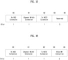
- reserved values of the Control ID subfield may be used to indicate newly defined OM Control fields.
- reserved values (e.g., 10 to 14) of the Control ID subfield may be used to indicate OM Control fields for non-legacy.
- ControlID value Meaning 0 Triggered response scheduling (TRS) 1 Operating mode (OM) 2 HE link adaptation (HLA) 3 Buffer status report (BSR) 4 UL power headroom (UPH) 5 Bandwidth query report (BQR) 6 Command and status (CAS) 7 EHT operating mode (EHT OM) 8 Single response scheduling (SRS) 9 AP assistance request (AAR) 10 extended OM control field or OM control extension field 11-14 Reserved 15 Ones need expansion surely (ONES)
- the newly defined extended OM Control field or OM Control Extension field as described above may be configured to include the following information.
- the extended OM Control field or OM Control Extension field may include Channel Width information.
- the Channel Width information may indicate a bandwidth supported by a non-legacy STA.
- the information may be composed of 3-bit information as shown in Table 14 below. [Table 14] Channel Width value Indication 0 20MHz 1 40MHz 2 80MHz 3 160MHz 4 320MHz 5 480MHz 6 560MHz 7 640MHz
- the indication information according to the value may be changed depending on whether 480MHz/560MHz/640MHz is supported in the STA.
- the extended OM Control field or OM Control Extension field may include Rx NSS (number of spatial streams) information.
- the information may indicate the maximum NSS supported upon reception and may be configured with 4 bits to support up to 16 ss.
- the extended OM Control field or OM Control Extension field may contain Tx NSS information.
- the information may indicate the maximum NSS supported during transmission and may be configured with 4 bits to support up to 16 ss.
- the extended OM Control field or OM Control Extension field may include a UL MU Disable subfield, a UL MU Data Disable subfield, an ER SU Disable subfield, and/or a DL MU-MIMO Resound Recommendation subfield as mentioned in FIG. 14 .
- FIG. 17 is an example of a non-legacy OM Control field considering an extended BW indication to which the present disclosure may be applied.
- the non-legacy OM Control field may include a 3-bit Channel Width subfield, a 4-bit Tx NSS subfield, a 4-bit Rx NSS subfield, a 1-bit ER SU Disable subfield, a 1-bit DL MU-MIMO Resound Recommendation subfield, a 1-bit UL MU Disable subfield, and a 1-bit UL MU Data Disable subfield.
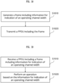
- FIG. 18 is a diagram for explaining an example of a method for transmitting bandwidth indication information according to the present disclosure.
- the STA may generate a frame including information on an indication of an operating channel width.
- information on the indication of the operating channel width may be included in an operating mode (OM) control subfield in an aggregated-control (A-control) field of the frame.
- the OM control subfield may include a specific subfield capable of indicating a wide bandwidth greater than 320 MHz.
- the OM control subfield may include a channel width extension subfield (e.g., a Channel Width Extension subfield in FIG. 15 ) related to the indication of an operating channel width of up to 320 MHz.
- the wide bandwidth may include one or more of a 480 MHz bandwidth, a 560 MHz bandwidth, or a 640 MHz bandwidth.
- the specific subfield may be constructed with at least two bits of B3 to B5 of the OM control subfield.
- the remaining 1 bit among B3 to B5 may be reserved.
- a specific subfield set to a value 0 may indicate a bandwidth less than or equal to 320 MHz
- a specific subfield set to a value 1 may indicate a bandwidth of 480 MHz
- a specific subfield set to a value 2 may indicate a bandwidth of 560 MHz
- a specific subfield set to a value 3 may indicate a bandwidth of 640 MHz.
- a specific subfield set to a value 0 indicates a bandwidth less than or equal to 320 MHz
- a specific subfield set to a value 1 indicates a bandwidth of 480 MHz
- a specific subfield set to a value 2 indicates a bandwidth of 560 MHz
- a specific subfield set to a value 3 indicates a bandwidth of 640 MHz
- values 4 to 7 may be reserved.
- an operating channel width for the STA may be determined based on a number of subfields included in the OM control subfield.
- the specific subfield may be located following the Tx NSTS (number of space time streams) extension subfield within the OM control subfield.
- the STA may transmit a PPDU including the aforementioned frame.
- the method performed by the STA described in the example of FIG. 18 may be performed by the first device (100) of FIG. 1 .
- one or more processors (102) of the first device (100) of FIG. 1 may be configured to generate a frame including information for an indication of an operating channel width, and transmit a PPDU including the frame via one or more transceivers (106).
- one or more memories (104) of the first device (100) may store commands for performing the method described in the example of FIG. 18 when executed by one or more processors (102).
- FIG. 19 is a diagram for explaining an example of a method for receiving bandwidth indication information according to the present disclosure.
- the STA may receive a physical protocol data unit (PPDU) including a frame including information for an indication of an operating channel width.
- PPDU physical protocol data unit
- information for the indication of the operating channel width may be included in an operating mode (OM) control subfield within an aggregated-control (A-control) field of the frame.
- the OM control subfield may include a specific subfield capable of indicating a wide bandwidth greater than 320 MHz.
- the STA may perform an operation (e.g., ACK/NACK feedback operation, etc.) based on information for the indication of the operating channel width.
- an operation e.g., ACK/NACK feedback operation, etc.
- Examples of information for indication on the width of the operating channel, examples of OM control subfields, and specific details for specific subfields are the same as those in the example of Fig. 18 described above, so redundant descriptions are omitted.
- the method performed by the STA described in the example of FIG. 19 may be performed by the second device (200) of FIG. 1 .
- one or more processors (202) of the second device (200) of FIG. 1 may be configured to receive a PPDU (physical protocol data unit) including a frame including information for an indication of an operating channel width through one or more transceivers (206), and perform an operation based on the information for the indication of the operating channel width.
- one or more memories (204) of the second device (200) may store commands for performing the method described in the example of FIG. 19 when executed by one or more processors (202).
- the operating channel width indication proposed in the present disclosure has a new feature of including more information for indicating the operating channel width for a wide bandwidth greater than 320 MHz.
- the throughput and efficiency aspects in the wireless LAN system may be enhanced.
- Embodiments described above are that elements and features of the present disclosure are combined in a predetermined form. Each element or feature should be considered to be optional unless otherwise explicitly mentioned. Each element or feature may be implemented in a form that it is not combined with other element or feature.
- an embodiment of the present disclosure may include combining a part of elements and/or features. An order of operations described in embodiments of the present disclosure may be changed. Some elements or features of one embodiment may be included in other embodiment or may be substituted with a corresponding element or a feature of other embodiment. It is clear that an embodiment may include combining claims without an explicit dependency relationship in claims or may be included as a new claim by amendment after application.
- a scope of the present disclosure includes software or machine-executable commands (e.g., an operating system, an application, a firmware, a program, etc.) which execute an operation according to a method of various embodiments in a device or a computer and a non-transitory computer-readable medium that such a software or a command, etc. are stored and are executable in a device or a computer.
- a command which may be used to program a processing system performing a feature described in the present disclosure may be stored in a storage medium or a computer-readable storage medium and a feature described in the present disclosure may be implemented by using a computer program product including such a storage medium.
- a storage medium may include a high-speed random-access memory such as DRAM, SRAM, DDR RAM or other random-access solid state memory device, but it is not limited thereto, and it may include a nonvolatile memory such as one or more magnetic disk storage devices, optical disk storage devices, flash memory devices or other nonvolatile solid state storage devices.
- a memory optionally includes one or more storage devices positioned remotely from processor(s).
- a memory or alternatively, nonvolatile memory device(s) in a memory include a non-transitory computer-readable storage medium.
- a feature described in the present disclosure may be stored in any one of machine-readable mediums to control a hardware of a processing system and may be integrated into a software and/or a firmware which allows a processing system to interact with other mechanism utilizing a result from an embodiment of the present disclosure.
- a software or a firmware may include an application code, a device driver, an operating system and an execution environment/container, but it is not limited thereto.
- a method proposed by the present disclosure is mainly described based on an example applied to an IEEE 802.11-based system, 5G system, but may be applied to various WLAN or wireless communication systems other than the IEEE 802.11-based system.
Landscapes
- Engineering & Computer Science (AREA)
- Signal Processing (AREA)
- Computer Networks & Wireless Communication (AREA)
- Mobile Radio Communication Systems (AREA)
Applications Claiming Priority (3)
| Application Number | Priority Date | Filing Date | Title |
|---|---|---|---|
| KR20220068364 | 2022-06-03 | ||
| KR20220070926 | 2022-06-10 | ||
| PCT/KR2023/007502 WO2023234720A1 (ko) | 2022-06-03 | 2023-06-01 | 무선랜 시스템에서 확장된 대역폭을 위한 동작 모드를 지시하는 방법 및 장치 |
Publications (1)
| Publication Number | Publication Date |
|---|---|
| EP4535898A1 true EP4535898A1 (de) | 2025-04-09 |
Family
ID=89025208
Family Applications (1)
| Application Number | Title | Priority Date | Filing Date |
|---|---|---|---|
| EP23816380.2A Pending EP4535898A1 (de) | 2022-06-03 | 2023-06-01 | Verfahren und vorrichtung zur steuerung des betriebsmodus für erweiterte bandbreite in einem wlan-system |
Country Status (5)
| Country | Link |
|---|---|
| EP (1) | EP4535898A1 (de) |
| JP (1) | JP2025518809A (de) |
| KR (1) | KR20250003875A (de) |
| CN (1) | CN119302020A (de) |
| WO (1) | WO2023234720A1 (de) |
Families Citing this family (2)
| Publication number | Priority date | Publication date | Assignee | Title |
|---|---|---|---|---|
| JP2024006492A (ja) * | 2022-07-01 | 2024-01-17 | キヤノン株式会社 | 通信装置、通信方法、及び、プログラム |
| WO2025151279A2 (en) * | 2024-01-11 | 2025-07-17 | Qualcomm Incorporated | Secure control frames in wireless communications |
Family Cites Families (4)
| Publication number | Priority date | Publication date | Assignee | Title |
|---|---|---|---|---|
| US11510098B2 (en) * | 2017-08-11 | 2022-11-22 | Intel Corporation | Determining a number of spatial streams and a bandwidth |
| US11115104B2 (en) * | 2018-05-25 | 2021-09-07 | Intel Corporation | Enhanced signaling and use of multiple transmission chains |
| US11160084B2 (en) * | 2018-07-05 | 2021-10-26 | Qualcomm Incorporated | Supporting 320 MHz operating BW |
| US11515982B2 (en) * | 2020-11-12 | 2022-11-29 | Qualcomm Incorporated | Special user information field for trigger frame |
-
2023
- 2023-06-01 EP EP23816380.2A patent/EP4535898A1/de active Pending
- 2023-06-01 JP JP2024571050A patent/JP2025518809A/ja active Pending
- 2023-06-01 KR KR1020247038282A patent/KR20250003875A/ko active Pending
- 2023-06-01 WO PCT/KR2023/007502 patent/WO2023234720A1/ko not_active Ceased
- 2023-06-01 CN CN202380044509.3A patent/CN119302020A/zh active Pending
Also Published As
| Publication number | Publication date |
|---|---|
| KR20250003875A (ko) | 2025-01-07 |
| WO2023234720A1 (ko) | 2023-12-07 |
| CN119302020A (zh) | 2025-01-10 |
| JP2025518809A (ja) | 2025-06-19 |
Similar Documents
| Publication | Publication Date | Title |
|---|---|---|
| EP4362588A1 (de) | Verfahren und vorrichtung zur durchführung von bandbreitensignalisierung eines auslöserrahmens in einem wlan-system | |
| EP4325970A1 (de) | Übertragungsverfahren und -vorrichtung auf der basis von präambelpunktierung in einem wlan-system | |
| EP4333527A1 (de) | Verfahren und vorrichtung zur durchführung eines sounding-verfahrens in einem wlan-system | |
| EP4462914A1 (de) | Verfahren und vorrichtung zur verteilten zuweisung mehrerer ressourceneinheiten in einem wlan-system | |
| EP4366368A1 (de) | Verfahren und vorrichtung zur durchführung eines erfassungsverfahrens in einem wlan-system | |
| EP4486046A1 (de) | Verfahren und vorrichtung zum senden oder empfangen auf der basis eines netzwerkzuweisungsvektors in einem wlan-system | |
| EP4525540A1 (de) | Triggerrahmenbasiertes ppdu-sende-/empfangsverfahren und -vorrichtung in einem wlan-system | |
| US12212999B2 (en) | Method and apparatus for transmitting and receiving protocol data unit-related information in wireless LAN system | |
| EP4322432A1 (de) | Verfahren und vorrichtung zur übertragung auf der basis eines duplikationsmodus in einem wlan-system | |
| EP4336763A1 (de) | Verfahren und vorrichtung zur durchführung eines sounding-verfahrens in einem wlan-system | |
| US12302418B2 (en) | Method and device for transmitting or receiving access point-related information in wireless LAN system | |
| EP4535898A1 (de) | Verfahren und vorrichtung zur steuerung des betriebsmodus für erweiterte bandbreite in einem wlan-system | |
| EP4513837A1 (de) | Verfahren und vorrichtung für breitbandige ppdu-übertragung oder -empfang in einem wlan-system | |
| EP4513838A1 (de) | Verfahren und vorrichtung für aggregierte übertragung und empfang einer protokolldateneinheit der physikalischen schicht in einem wlan-system | |
| EP4507257A1 (de) | Verfahren und vorrichtung zum senden oder empfangen von ppdu mit einer betriebsbezogenen präambel mit mehreren zugangspunkten in einem wlan-system | |
| EP4513841A1 (de) | Verfahren und vorrichtung zum senden oder empfangen von stf für neue numerologie in einem wlan-system | |
| EP4513839A1 (de) | Verfahren und vorrichtung zum senden oder empfangen von stf für neue numerologie in einem wlan-system | |
| EP4498743A1 (de) | Signalisierungsverfahren und -vorrichtung für ressourcenmultiplex-mehrfachzugriff auf basis des betriebs mehrerer zugangspunkte in einem wlan-system | |
| US20240298304A1 (en) | Method and apparatus for carrying out communication on basis of operating mode control information in wireless lan system | |
| US20240372645A1 (en) | Method and apparatus for signaling inactive frequency unit information in wireless lan system | |
| US20240172191A1 (en) | Method and apparatus for trigger-based resource adaptive transmission in wireless lan system | |
| EP4535895A1 (de) | Triggerrahmenbasiertes ppdu-übertragungs- oder empfangsverfahren und -vorrichtung in einem wlan-system | |
| EP4513795A1 (de) | Verfahren und vorrichtung zur durchführung einer auf präambelpunktierung basierenden kommunikation in einem wlan-system | |
| EP4513842A1 (de) | Verfahren und vorrichtung zum senden oder empfangen von stf für neue numerologie in einem wlan-system | |
| EP4525544A1 (de) | Verfahren und vorrichtung zur durchführung eines erfassungsverfahrens in einem wlan-system |
Legal Events
| Date | Code | Title | Description |
|---|---|---|---|
| STAA | Information on the status of an ep patent application or granted ep patent |
Free format text: STATUS: THE INTERNATIONAL PUBLICATION HAS BEEN MADE |
|
| PUAI | Public reference made under article 153(3) epc to a published international application that has entered the european phase |
Free format text: ORIGINAL CODE: 0009012 |
|
| STAA | Information on the status of an ep patent application or granted ep patent |
Free format text: STATUS: REQUEST FOR EXAMINATION WAS MADE |
|
| 17P | Request for examination filed |
Effective date: 20241220 |
|
| AK | Designated contracting states |
Kind code of ref document: A1 Designated state(s): AL AT BE BG CH CY CZ DE DK EE ES FI FR GB GR HR HU IE IS IT LI LT LU LV MC ME MK MT NL NO PL PT RO RS SE SI SK SM TR |
|
| DAV | Request for validation of the european patent (deleted) | ||
| DAX | Request for extension of the european patent (deleted) |