EP4525540A1 - Triggerrahmenbasiertes ppdu-sende-/empfangsverfahren und -vorrichtung in einem wlan-system - Google Patents
Triggerrahmenbasiertes ppdu-sende-/empfangsverfahren und -vorrichtung in einem wlan-system Download PDFInfo
- Publication number
- EP4525540A1 EP4525540A1 EP23803809.5A EP23803809A EP4525540A1 EP 4525540 A1 EP4525540 A1 EP 4525540A1 EP 23803809 A EP23803809 A EP 23803809A EP 4525540 A1 EP4525540 A1 EP 4525540A1
- Authority
- EP
- European Patent Office
- Prior art keywords
- ppdu
- value
- subfield
- legacy
- info field
- Prior art date
- Legal status (The legal status is an assumption and is not a legal conclusion. Google has not performed a legal analysis and makes no representation as to the accuracy of the status listed.)
- Pending
Links
Images


Classifications
-
- H—ELECTRICITY
- H04—ELECTRIC COMMUNICATION TECHNIQUE
- H04W—WIRELESS COMMUNICATION NETWORKS
- H04W74/00—Wireless channel access
- H04W74/002—Transmission of channel access control information
-
- H—ELECTRICITY
- H04—ELECTRIC COMMUNICATION TECHNIQUE
- H04W—WIRELESS COMMUNICATION NETWORKS
- H04W74/00—Wireless channel access
- H04W74/04—Scheduled access
- H04W74/06—Scheduled access using polling
-
- H—ELECTRICITY
- H04—ELECTRIC COMMUNICATION TECHNIQUE
- H04L—TRANSMISSION OF DIGITAL INFORMATION, e.g. TELEGRAPHIC COMMUNICATION
- H04L5/00—Arrangements affording multiple use of the transmission path
- H04L5/003—Arrangements for allocating sub-channels of the transmission path
- H04L5/0044—Allocation of payload; Allocation of data channels, e.g. PDSCH or PUSCH
-
- H—ELECTRICITY
- H04—ELECTRIC COMMUNICATION TECHNIQUE
- H04B—TRANSMISSION
- H04B7/00—Radio transmission systems, i.e. using radiation field
- H04B7/02—Diversity systems; Multi-antenna system, i.e. transmission or reception using multiple antennas
- H04B7/04—Diversity systems; Multi-antenna system, i.e. transmission or reception using multiple antennas using two or more spaced independent antennas
- H04B7/0413—MIMO systems
- H04B7/0452—Multi-user MIMO systems
-
- H—ELECTRICITY
- H04—ELECTRIC COMMUNICATION TECHNIQUE
- H04L—TRANSMISSION OF DIGITAL INFORMATION, e.g. TELEGRAPHIC COMMUNICATION
- H04L27/00—Modulated-carrier systems
- H04L27/26—Systems using multi-frequency codes
-
- H—ELECTRICITY
- H04—ELECTRIC COMMUNICATION TECHNIQUE
- H04L—TRANSMISSION OF DIGITAL INFORMATION, e.g. TELEGRAPHIC COMMUNICATION
- H04L5/00—Arrangements affording multiple use of the transmission path
- H04L5/003—Arrangements for allocating sub-channels of the transmission path
- H04L5/0053—Allocation of signalling, i.e. of overhead other than pilot signals
-
- H—ELECTRICITY
- H04—ELECTRIC COMMUNICATION TECHNIQUE
- H04L—TRANSMISSION OF DIGITAL INFORMATION, e.g. TELEGRAPHIC COMMUNICATION
- H04L5/00—Arrangements affording multiple use of the transmission path
- H04L5/0091—Signalling for the administration of the divided path, e.g. signalling of configuration information
- H04L5/0094—Indication of how sub-channels of the path are allocated
-
- H—ELECTRICITY
- H04—ELECTRIC COMMUNICATION TECHNIQUE
- H04W—WIRELESS COMMUNICATION NETWORKS
- H04W72/00—Local resource management
- H04W72/04—Wireless resource allocation
- H04W72/044—Wireless resource allocation based on the type of the allocated resource
-
- H—ELECTRICITY
- H04—ELECTRIC COMMUNICATION TECHNIQUE
- H04W—WIRELESS COMMUNICATION NETWORKS
- H04W72/00—Local resource management
- H04W72/04—Wireless resource allocation
- H04W72/044—Wireless resource allocation based on the type of the allocated resource
- H04W72/0453—Resources in frequency domain, e.g. a carrier in FDMA
-
- H—ELECTRICITY
- H04—ELECTRIC COMMUNICATION TECHNIQUE
- H04W—WIRELESS COMMUNICATION NETWORKS
- H04W72/00—Local resource management
- H04W72/20—Control channels or signalling for resource management
-
- H—ELECTRICITY
- H04—ELECTRIC COMMUNICATION TECHNIQUE
- H04W—WIRELESS COMMUNICATION NETWORKS
- H04W84/00—Network topologies
- H04W84/02—Hierarchically pre-organised networks, e.g. paging networks, cellular networks, WLAN [Wireless Local Area Network] or WLL [Wireless Local Loop]
- H04W84/10—Small scale networks; Flat hierarchical networks
- H04W84/12—WLAN [Wireless Local Area Networks]
Definitions
- the present disclosure relates to a method and device for transmitting or receiving a physical layer protocol data unit (PPDU) based on a trigger frame in a wireless local area network (WLAN) system.
- PPDU physical layer protocol data unit
- Wi-Fi Wireless LAN
- technologies recently introduced to WLAN include enhancements for Very High-Throughput (VHT) of the 802.11 ac standard, and enhancements for High Efficiency (HE) of the IEEE 802.11ax standard.
- VHT Very High-Throughput
- HE High Efficiency
- EHT Extremely High Throughput
- MIMO Multiple Input Multiple Output
- APs multiple access points
- UHR ultra high reliability
- a technical object of the present disclosure is to provide a method and device for transmitting or receiving a physical layer protocol data unit (PPDU) based on a trigger frame in a wireless LAN system.
- PPDU physical layer protocol data unit
- a technical object of the present disclosure is to provide a method and device for performing transmission or reception of a merged PPDU for different versions of PPDU based on a trigger frame.
- a method performed by a station (STA) in a wireless LAN system may comprise: receiving a trigger frame including a common info field from an access point (AP); and transmitting to the AP, a TB PPDU corresponding to one of one or more trigger based physical layer protocol data units (TB PPDU) triggered by the trigger frame.
- the common info field may include an aggregated PPDU (A-PPDU) related subfield
- A-PPDU aggregated PPDU
- a configuration of the one or more TB PPDUs may be indicated based on the A-PPDU related subfield and at least one other subfield included in the common info field.
- a method performed by an access point (AP) in a wireless LAN system may comprise: transmitting a trigger frame including a common info field to a station (STA); and receiving from the STA, a TB PPDU corresponding to one of one or more trigger based physical layer protocol data units (TB PPDU) triggered by the trigger frame.
- the common info field may include an aggregated PPDU (A-PPDU) related subfield, and a configuration of the one or more TB PPDUs may be indicated based on the A-PPDU related subfield and at least one other subfield included in the common info field.
- a method and device for allocating a resource unit in a wireless LAN system may be provided.
- a method and device for performing transmission or reception of a merged PPDU for different versions of PPDUs based on a trigger frame may be provided.
- known structures and devices may be omitted or may be shown in a form of a block diagram based on a core function of each structure and device in order to prevent a concept of the present disclosure from being ambiguous.
- an element when referred to as being “connected”, “combined” or “linked” to another element, it may include an indirect connection relation that yet another element presents therebetween as well as a direct connection relation.
- a term, “include” or “have”, specifies the presence of a mentioned feature, step, operation, component and/or element, but it does not exclude the presence or addition of one or more other features, stages, operations, components, elements and/or their groups.
- a term such as “first”, “second”, etc. is used only to distinguish one element from other element and is not used to limit elements, and unless otherwise specified, it does not limit an order or importance, etc. between elements. Accordingly, within a scope of the present disclosure, a first element in an embodiment may be referred to as a second element in another embodiment and likewise, a second element in an embodiment may be referred to as a first element in another embodiment.
- a term used in the present disclosure is to describe a specific embodiment, and is not to limit a claim. As used in a described and attached claim of an embodiment, a singular form is intended to include a plural form, unless the context clearly indicates otherwise.
- a term used in the present disclosure, "and/or”, may refer to one of related enumerated items or it means that it refers to and includes any and all possible combinations of two or more of them.
- "/" between words in the present disclosure has the same meaning as “and/or”, unless otherwise described.
- Examples of the present disclosure may be applied to various wireless communication systems.
- examples of the present disclosure may be applied to a wireless LAN system.
- examples of the present disclosure may be applied to an IEEE 802.11a/g/n/ac/ax standards-based wireless LAN.
- examples of the present disclosure may be applied to a wireless LAN based on the newly proposed IEEE 802.11be (or EHT) standard.
- Examples of the present disclosure may be applied to an IEEE 802.11be Release-2 standard-based wireless LAN corresponding to an additional enhancement technology of the IEEE 802.11be Release-1 standard.
- examples of the present disclosure may be applied to a next-generation standards-based wireless LAN after IEEE 802.11be.
- examples of this disclosure may be applied to a cellular wireless communication system. For example, it may be applied to a cellular wireless communication system based on Long Term Evolution (LTE)-based technology and 5G New Radio (NR)-based technology of the 3rd Generation Partnership Project (3GPP) standard.
- LTE Long Term Evolution
- FIG. 1 illustrates a block diagram of a wireless communication device according to an embodiment of the present disclosure.
- the first device 100 and the second device 200 illustrated in FIG. 1 may be replaced with various terms such as a terminal, a wireless device, a Wireless Transmit Receive Unit (WTRU), an User Equipment (UE), a Mobile Station (MS), an user terminal (UT), a Mobile Subscriber Station (MSS), a Mobile Subscriber Unit (MSU), a subscriber station (SS), an advanced mobile station (AMS), a wireless terminal (WT), or simply user, etc.
- WTRU Wireless Transmit Receive Unit
- UE User Equipment
- MS Mobile Station
- UT User terminal
- MSS Mobile Subscriber Station
- MSU Mobile Subscriber Unit
- SS subscriber station
- AMS advanced mobile station
- WT wireless terminal
- the first device 100 and the second device 200 include an access point (AP), a base station (BS), a fixed station, a Node B, a base transceiver system (BTS), a network, It may be replaced with various terms such as an Artificial Intelligence (AI) system, a road side unit (RSU), a repeater, a router, a relay, and a gateway.
- AP access point
- BS base station
- BTS base transceiver system
- AI Artificial Intelligence
- RSU road side unit
- RSU repeater
- router a relay
- gateway a gateway
- the devices 100 and 200 illustrated in FIG. 1 may be referred to as stations (STAs).
- the devices 100 and 200 illustrated in FIG. 1 may be referred to by various terms such as a transmitting device, a receiving device, a transmitting STA, and a receiving STA.
- the STAs 110 and 200 may perform an access point (AP) role or a non-AP role. That is, in the present disclosure, the STAs 110 and 200 may perform functions of an AP and/or a non-AP.
- AP access point
- the STAs 110 and 200 may perform functions of an AP and/or a non-AP.
- an AP may also be indicated as an AP STA.
- the first device 100 and the second device 200 may transmit and receive radio signals through various wireless LAN technologies (e.g., IEEE 802.11 series).
- the first device 100 and the second device 200 may include an interface for a medium access control (MAC) layer and a physical layer (PHY) conforming to the IEEE 802.11 standard.
- MAC medium access control
- PHY physical layer
- the first device 100 and the second device 200 may additionally support various communication standards (e.g., 3GPP LTE series, 5G NR series standards, etc.) technologies other than wireless LAN technology.
- the device of the present disclosure may be implemented in various devices such as a mobile phone, a vehicle, a personal computer, augmented reality (AR) equipment, and virtual reality (VR) equipment, etc.
- the STA of the present specification may support various communication services such as a voice call, a video call, data communication, autonomous-driving, machine-type communication (MTC), machine-to-machine (M2M), device-to-device (D2D), IoT (Internet-of-Things), etc.
- MTC machine-type communication
- M2M machine-to-machine
- D2D device-to-device
- IoT Internet-of-Things
- a first device 100 may include one or more processors 102 and one or more memories 104 and may additionally include one or more transceivers 106 and/or one or more antennas 108.
- a processor 102 may control a memory 104 and/or a transceiver 106 and may be configured to implement description, functions, procedures, proposals, methods and/or operation flow charts disclosed in the present disclosure.
- a processor 102 may transmit a wireless signal including first information/signal through a transceiver 106 after generating first information/signal by processing information in a memory 104.
- a processor 102 may receive a wireless signal including second information/signal through a transceiver 106 and then store information obtained by signal processing of second information/signal in a memory 104.
- one or more protocol layers may be implemented by one or more processors 102, 202.
- one or more processors 102, 202 may implement one or more layers (e.g., a functional layer such as PHY, MAC).
- One or more processors 102, 202 may generate one or more PDUs (Protocol Data Unit) and/or one or more SDUs (Service Data Unit) according to description, functions, procedures, proposals, methods and/or operation flow charts disclosed in the present disclosure.
- PDUs Protocol Data Unit
- SDUs Service Data Unit
- One or more processors 102, 202 may receive a signal (e.g., a baseband signal) from one or more transceivers 106, 206 and obtain a PDU, a SDU, a message, control information, data or information according to description, functions, procedures, proposals, methods and/or operation flow charts disclosed in the present disclosure.
- a signal e.g., a baseband signal
- One or more processors 102, 202 may be referred to as a controller, a micro controller, a micro processor or a micro computer.
- One or more processors 102, 202 may be implemented by a hardware, a firmware, a software, or their combination.
- one or more ASICs Application Specific Integrated Circuit
- one or more DSPs Digital Signal Processor
- one or more DSPDs Digital Signal Processing Device
- one or more PLDs PROgrammable Logic Device
- FPGAs Field Programmable Gate Arrays
- Description, functions, procedures, proposals, methods and/or operation flow charts disclosed in the present disclosure may be implemented by using a firmware or a software and a firmware or a software may be implemented to include a module, a procedure, a function, etc.
- a firmware or a software configured to perform description, functions, procedures, proposals, methods and/or operation flow charts disclosed in the present disclosure may be included in one or more processors 102, 202 or may be stored in one or more memories 104, 204 and driven by one or more processors 102, 202.
- Description, functions, procedures, proposals, methods and/or operation flow charts disclosed in the present disclosure may be implemented by using a firmware or a software in a form of a code, an instruction and/or a set of instructions.
- One or more memories 104, 204 may be connected to one or more processors 102, 202 and may store data, a signal, a message, information, a program, a code, an indication and/or an instruction in various forms.
- One or more memories 104, 204 may be configured with ROM, RAM, EPROM, a flash memory, a hard drive, a register, a cash memory, a computer readable storage medium and/or their combination.
- One or more memories 104, 204 may be positioned inside and/or outside one or more processors 102, 202.
- one or more memories 104, 204 may be connected to one or more processors 102, 202 through a variety of technologies such as a wire or wireless connection.
- One or more transceivers 106, 206 may transmit user data, control information, a wireless signal/channel, etc. mentioned in methods and/or operation flow charts, etc. of the present disclosure to one or more other devices.
- One or more transceivers 106, 206 may receiver user data, control information, a wireless signal/channel, etc. mentioned in description, functions, procedures, proposals, methods and/or operation flow charts, etc. disclosed in the present disclosure from one or more other devices.
- one or more transceivers 106, 206 may be connected to one or more processors 102, 202 and may transmit and receive a wireless signal.
- one or more processors 102, 202 may control one or more transceivers 106, 206 to transmit user data, control information or a wireless signal to one or more other devices.
- one or more processors 102, 202 may control one or more transceivers 106, 206 to receive user data, control information or a wireless signal from one or more other devices.
- one or more transceivers 106, 206 may be connected to one or more antennas 108, 208 and one or more transceivers 106, 206 may be configured to transmit and receive user data, control information, a wireless signal/channel, etc. mentioned in description, functions, procedures, proposals, methods and/or operation flow charts, etc.
- one or more antennas may be a plurality of physical antennas or a plurality of logical antennas (e.g., an antenna port).
- One or more transceivers 106, 206 may convert a received wireless signal/channel, etc. into a baseband signal from a RF band signal to process received user data, control information, wireless signal/channel, etc. by using one or more processors 102, 202.
- One or more transceivers 106, 206 may convert user data, control information, a wireless signal/channel, etc. which are processed by using one or more processors 102, 202 from a baseband signal to a RF band signal.
- one or more transceivers 106, 206 may include an (analogue) oscillator and/or a filter.
- one of the STAs 100 and 200 may perform an intended operation of an AP, and the other of the STAs 100 and 200 may perform an intended operation of a non-AP STA.
- the transceivers 106 and 206 of FIG. 1 may perform a transmission and reception operation of a signal (e.g., a packet or a physical layer protocol data unit (PPDU) conforming to IEEE 802.11a/b/g/n/ac/ax/be).
- a signal e.g., a packet or a physical layer protocol data unit (PPDU) conforming to IEEE 802.11a/b/g/n/ac/ax/be.
- PPDU physical layer protocol data unit
- an operation in which various STAs generate transmission/reception signals or perform data processing or calculation in advance for transmission/reception signals may be performed by the processors 102 and 202 of FIG. 1 .
- an example of an operation of generating a transmission/reception signal or performing data processing or calculation in advance for the transmission/reception signal may include 1) Determining / acquiring / configuring / calculating / decoding / encoding bit information of fields (signal (SIG), short training field (STF), long training field (LTF), Data, etc.) included in the PPDU, 2) Determining / configuring / acquiring time resources or frequency resources (e.g., subcarrier resources) used for fields (SIG, STF, LTF, Data, etc.) included in the PPDU; 3) Determining / configuring / acquiring a specific sequence (e.g., pilot sequence, STF/LTF sequence, extra sequence applied to SIG) used for fields (SIG, STF, LTF, Data, etc.) included in the PPDU action, 4) power control operation and/or power saving operation applied to the STA, 5) Operations related to ACK signal determination/acquisition/configuration/calculation/decoding/en
- various information e.g., information related to fields / subfields / control fields / parameters / power, etc.
- various STAs may be stored in the memories 104 and 204 of FIG. 1 .
- downlink may mean a link for communication from an AP STA to a non-AP STA, and a DL PPDU / packet / signal may be transmitted and received through the DL.
- a transmitter may be part of an AP STA, and a receiver may be part of a non-AP STA.
- Uplink may mean a link for communication from non-AP STAs to AP STAs, and a UL PPDU / packet / signal may be transmitted and received through the UL.
- a transmitter may be part of a non-AP STA, and a receiver may be part of an AP STA.
- FIG. 2 is a diagram illustrating an exemplary structure of a wireless LAN system to which the present disclosure may be applied.
- the structure of the wireless LAN system may consist of be composed of a plurality of components.
- a wireless LAN supporting STA mobility transparent to an upper layer may be provided by interaction of a plurality of components.
- a Basic Service Set (BSS) corresponds to a basic construction block of a wireless LAN.
- FIG. 2 exemplarily shows that two BSSs (BSS1 and BSS2) exist and two STAs are included as members of each BSS (STA1 and STA2 are included in BSS1, and STA3 and STA4 are included in BSS2).
- An ellipse representing a BSS in FIG. 2 may also be understood as representing a coverage area in which STAs included in the corresponding BSS maintain communication. This area may be referred to as a Basic Service Area (BSA).
- BSA Basic Service Area
- IBSS independent BSS
- IBSS may have a minimal form contaning only two STAs.
- BSS1 contaning only STA1 and STA2 or BSS2 contaning only STA3 and STA4 may respectively correspond to representative examples of IBSS.
- This configuration is possible when STAs may communicate directly without an AP.
- this type of wireless LAN it is not configured in advance, but may be configured when a LAN is required, and this may be referred to as an ad-hoc network. Since the IBSS does not include an AP, there is no centralized management entity. That is, in IBSS, STAs are managed in a distributed manner. In IBSS, all STAs may be made up of mobile STAs, and access to the distributed system (DS) is not allowed, forming a self-contained network.
- DS distributed system
- STA Membership of an STA in the BSS may be dynamically changed by turning on or off the STA, entering or exiting the BSS area, and the like.
- the STA may join the BSS using a synchronization process.
- the STA shall be associated with the BSS. This association may be dynamically established and may include the use of a Distribution System Service (DSS).
- DSS Distribution System Service
- a direct STA-to-STA distance in a wireless LAN may be limited by PHY performance. In some cases, this distance limit may be sufficient, but in some cases, communication between STAs at a longer distance may be required.
- a distributed system (DS) may be configured to support extended coverage.
- DS means a structure in which BSSs are interconnected.
- a BSS may exist as an extended form of a network composed of a plurality of BSSs.
- DS is a logical concept and may be specified by the characteristics of Distributed System Media (DSM).
- DSM Distributed System Media
- a wireless medium (WM) and a DSM may be logically separated.
- Each logical medium is used for a different purpose and is used by different components. These medium are not limited to being the same, nor are they limited to being different.
- the flexibility of the wireless LAN structure may be explained in that a plurality of media are logically different. That is, the wireless LAN structure may be implemented in various ways, and the corresponding wireless LAN structure may be independently specified by the physical characteristics of each embodiment.
- a DS may support a mobile device by providing seamless integration of a plurality of BSSs and providing logical services necessary to address an address to a destination.
- the DS may further include a component called a portal that serves as a bridge for connection between the wireless LAN and other networks (e.g., IEEE 802.X).
- the AP enables access to the DS through the WM for the associated non-AP STAs, and means an entity that also has the functionality of an STA.
- Data movement between the BSS and the DS may be performed through the AP.
- STA2 and STA3 shown in FIG. 2 have the functionality of STAs, and provide a function allowing the associated non-AP STAs (STA1 and STA4) to access the DS.
- all APs basically correspond to STAs, all APs are addressable entities.
- the address used by the AP for communication on the WM and the address used by the AP for communication on the DSM are not necessarily the same.
- a BSS composed of an AP and one or more STAs may be referred to as an infrastructure BSS.
- Data transmitted from one of the STA(s) associated with an AP to a STA address of the corresponding AP may be always received on an uncontrolled port and may be processed by an IEEE 802.1X port access entity.
- transmission data (or frames) may be delivered to the DS.
- an extended service set may be configured to provide wide coverage.
- An ESS means a network in which a network having an arbitrary size and complexity is composed of DSs and BSSs.
- the ESS may correspond to a set of BSSs connected to one DS. However, the ESS does not include the DS.
- An ESS network is characterized by being seen as an IBSS in the Logical Link Control (LLC) layer. STAs included in the ESS may communicate with each other, and mobile STAs may move from one BSS to another BSS (within the same ESS) transparently to the LLC.
- APs included in one ESS may have the same service set identification (SSID).
- the SSID is distinguished from the BSSID, which is an identifier of the BSS.
- the wireless LAN system does not assume anything about the relative physical locations of BSSs, and all of the following forms are possible.
- BSSs may partially overlap, which is a form commonly used to provide continuous coverage.
- BSSs may not be physically connected, and logically there is no limit on the distance between BSSs.
- the BSSs may be physically located in the same location, which may be used to provide redundancy.
- one (or more than one) IBSS or ESS networks may physically exist in the same space as one (or more than one) ESS network.
- an ad-hoc network When an ad-hoc network operates in a location where an ESS network exists, when physically overlapping wireless networks are configured by different organizations, or when two or more different access and security policies are required in the same location, this may correspond to the form of an ESS network in the like.
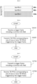
- FIG. 3 is a diagram for explaining a link setup process to which the present disclosure may be applied.
- an STA In order for an STA to set up a link with respect to a network and transmit/receive data, it first discovers a network, performs authentication, establishes an association, and need to perform the authentication process for security.
- the link setup process may also be referred to as a session initiation process or a session setup process.
- the processes of discovery, authentication, association, and security setting of the link setup process may be collectively referred to as an association process.
- the STA may perform a network discovery operation.
- the network discovery operation may include a scanning operation of the STA. That is, in order for the STA to access the network, it needs to find a network in which it can participate.
- the STA shall identify a compatible network before participating in a wireless network, and the process of identifying a network existing in a specific area is called scanning.
- FIG. 3 exemplarily illustrates a network discovery operation including an active scanning process.
- active scanning an STA performing scanning transmits a probe request frame to discover which APs exist around it while moving channels and waits for a response thereto.
- a responder transmits a probe response frame as a response to the probe request frame to the STA that has transmitted the probe request frame.
- the responder may be an STA that last transmitted a beacon frame in the BSS of the channel being scanned.
- the AP since the AP transmits the beacon frame, the AP becomes a responder, and in the IBSS, the STAs in the IBSS rotate to transmit the beacon frame, so the responder is not constant.
- a STA that transmits a probe request frame on channel 1 and receives a probe response frame on channel 1 may store BSS-related information included in the received probe response frame and may move to the next channel (e.g., channel 2) and perform scanning (i.e., transmission/reception of a probe request/response on channel 2) in the same manner.
- the next channel e.g., channel 2
- scanning i.e., transmission/reception of a probe request/response on channel 2
- the scanning operation may be performed in a passive scanning manner.
- a STA performing scanning waits for a beacon frame while moving channels.
- the beacon frame is one of the management frames defined in IEEE 802.11, and is periodically transmitted to notify the existence of a wireless network and to allow the STA performing scanning to find a wireless network and participate in the wireless network.
- the AP serves to transmit beacon frames periodically, and in the IBSS, STAs within the IBSS rotate to transmit beacon frames.
- the STA performing scanning receives a beacon frame, the STA stores information for the BSS included in the beacon frame and records beacon frame information in each channel while moving to another channel.
- the STA receiving the beacon frame may store BSS-related information included in the received beacon frame, move to the next channel, and perform scanning in the next channel in the same way. Comparing active scanning and passive scanning, active scanning has an advantage of having less delay and less power consumption than passive scanning.
- step S320 After the STA discovers the network, an authentication process may be performed in step S320.
- This authentication process may be referred to as a first authentication process in order to be clearly distinguished from the security setup operation of step S340 to be described later.
- the authentication process includes a process in which the STA transmits an authentication request frame to the AP, and in response to this, the AP transmits an authentication response frame to the STA.
- An authentication frame used for authentication request/response corresponds to a management frame.
- the authentication frame includes an authentication algorithm number, an authentication transaction sequence number, a status code, a challenge text, a robust security network (RSN), and a Finite Cyclic Group, etc. This corresponds to some examples of information that may be included in the authentication request/response frame, and may be replaced with other information or additional information may be further included.
- RSN robust security network
- the STA may transmit an authentication request frame to the AP.
- the AP may determine whether to allow authentication of the corresponding STA based on information included in the received authentication request frame.
- the AP may provide the result of the authentication process to the STA through an authentication response frame.
- an association process may be performed in step S330.
- the association process includes a process in which the STA transmits an association request frame to the AP, and in response, the AP transmits an association response frame to the STA.
- the association request frame may include information related to various capabilities, a beacon listen interval, a service set identifier (SSID), supported rates, supported channels, RSN, mobility domain, supported operating classes, Traffic Indication Map Broadcast request (TIM broadcast request), interworking service capability, etc.
- the association response frame may include information related to various capabilities, status code, association ID (AID), supported rates, enhanced distributed channel access (EDCA) parameter set, received channel power indicator (RCPI), received signal to noise indicator (RSNI), mobility domain, timeout interval (e.g., association comeback time), overlapping BSS scan parameters, TIM broadcast response, Quality of Service (QoS) map, etc. This corresponds to some examples of information that may be included in the association request/response frame, and may be replaced with other information or additional information may be further included.
- AID association ID
- EDCA enhanced distributed channel access
- RCPI received channel power indicator
- RSNI received signal to noise indicator
- timeout interval e.g., association comeback time
- overlapping BSS scan parameters
- a security setup process may be performed in step S340.
- the security setup process of step S340 may be referred to as an authentication process through Robust Security Network Association (RSNA) request/response, and the authentication process of step S320 is referred to as a first authentication process, and the security setup process of step S340 may also simply be referred to as an authentication process.
- RSNA Robust Security Network Association
- the security setup process of step S340 may include, for example, a process of setting up a private key through 4-way handshaking through an Extensible Authentication Protocol over LAN (EAPOL) frame.
- the security setup process may be performed according to a security scheme not defined in the IEEE 802.11 standard.
- FIG. 4 is a diagram for explaining a backoff process to which the present disclosure may be applied.
- a basic access mechanism of medium access control is a carrier sense multiple access with collision avoidance (CSMA/CA) mechanism.
- the CSMA/CA mechanism is also called Distributed Coordination Function (DCF) of IEEE 802.11 MAC, and basically adopts a "listen before talk" access mechanism.
- DCF Distributed Coordination Function
- the AP and/or STA may perform Clear Channel Assessment (CCA) sensing a radio channel or medium during a predetermined time interval (e.g., DCF Inter-Frame Space (DIFS)), prior to starting transmission.
- CCA Clear Channel Assessment
- DIFS DCF Inter-Frame Space
- the corresponding AP and/or STA does not start its own transmission and may set a delay period for medium access (e.g., a random backoff period) and attempt frame transmission after waiting.
- a delay period for medium access e.g., a random backoff period
- collision may be minimized.
- HCF Hybrid Coordination Function
- HCF is based on the DCF and Point Coordination Function (PCF).
- PCF is a polling-based synchronous access method and refers to a method in which all receiving APs and/or STAs periodically poll to receive data frames.
- HCF has Enhanced Distributed Channel Access (EDCA) and HCF Controlled Channel Access (HCCA).
- EDCA is a contention-based access method for a provider to provide data frames to multiple users, and HCCA uses a non-contention-based channel access method using a polling mechanism.
- the HCF includes a medium access mechanism for improving QoS (Quality of Service) of the wireless LAN, and may transmit QoS data in both a Contention Period (CP) and a Contention Free Period (CFP).
- QoS Quality of Service
- each of STAs may attempt to transmit data (or frames).
- each of STAs may respectively select a random backoff count and attempt transmission after waiting for a corresponding slot time.
- the random backoff count has a pseudo-random integer value and may be determined as one of values ranging from 0 to CW.
- CW is a contention window parameter value.
- the CW parameter is given CWmin as an initial value, but may take a value twice as large in case of transmission failure (e.g., when an ACK for the transmitted frame is not received).
- CW parameter value When the CW parameter value reaches CWmax, data transmission may be attempted while maintaining the CWmax value until data transmission is successful, and when data transmission is successful, the CWmin value is reset.
- the STA continuously monitors the medium while counting down the backoff slots according to the determined backoff count value.
- the medium is monitored for occupancy, it stops counting down and waits, and resumes the rest of the countdown when the medium becomes idle.
- STA3 may transmit the frame immediately after confirming that the medium is idle as much as DIFS. The remaining STAs monitor and wait for the medium to be occupied/busy. In the meantime, data to be transmitted may also occur in each of STA1, STA2, and STA5, and each STA waits as long as DIFS when the medium is monitored as idle, and then may perform a countdown of the backoff slot according to the random backoff count value selected by each STA. Assume that STA2 selects the smallest backoff count value and STA1 selects the largest backoff count value.
- STA1 and STA5 temporarily stop counting down and wait while STA2 occupies the medium.
- STA1 and STA5 wait for DIFS and resume the stopped backoff count. That is, frame transmission may be started after counting down the remaining backoff slots for the remaining backoff time. Since the remaining backoff time of STA5 is shorter than that of STA1, STA5 starts frame transmission. While STA2 occupies the medium, data to be transmitted may also occur in STA4.
- STA4 may wait for DIFS, and then may perform a countdown according to the random backoff count value selected by the STA4 and start transmitting frames.
- the example of FIG. 4 shows a case where the remaining backoff time of STA5 coincides with the random backoff count value of STA4 by chance. In this case, a collision may occur between STA4 and STA5. When a collision occurs, both STA4 and STA5 do not receive an ACK, so data transmission fails. In this case, STA4 and STA5 may double the CW value, select a random backoff count value, and perform a countdown.
- STA1 waits while the medium is occupied due to transmission of STA4 and STA5, waits for DIFS when the medium becomes idle, and then starts frame transmission after the remaining backoff time has elapsed.
- the data frame is a frame used for transmission of data forwarded to a higher layer, and may be transmitted after a backoff performed after DIFS elapses from when the medium becomes idle.
- the management frame is a frame used for exchange of management information that is not forwarded to a higher layer, and is transmitted after a backoff performed after an IFS such as DIFS or Point Coordination Function IFS (PIFS).
- IFS such as DIFS or Point Coordination Function IFS (PIFS).
- PIFS Point Coordination Function IFS
- a subtype frames of management frame there are a Beacon, an association request/response, a re-association request/response, a probe request/response, an authentication request/response, etc.
- a control frame is a frame used to control access to a medium.
- control frame As a subtype frames of control frame, there are Request-To-Send (RTS), Clear-To-Send (CTS), Acknowledgement (ACK), Power Save-Poll (PS-Poll), block ACK (BlockAck), block ACK request ( BlockACKReq), null data packet announcement (NDP announcement), and trigger, etc.
- RTS Request-To-Send
- CTS Clear-To-Send
- ACK Acknowledgement
- PS-Poll Power Save-Poll
- BlockAck block ACK
- BlockACKReq block ACK request
- NDP announcement null data packet announcement
- a Quality of Service (QoS) STA may perform the backoff that is performed after an arbitration IFS (AIFS) for an access category (AC) to which the frame belongs, that is, AIFS[i] (where i is a value determined by AC), and then may transmit the frame.
- AIFS arbitration IFS
- AC access category
- the frame in which AIFS[i] can be used may be a data frame, a management frame, or a control frame other than a response frame.
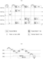
- FIG. 5 is a diagram for explaining a frame transmission operation based on CSMA/CA to which the present disclosure may be applied.
- the CSMA/CA mechanism includes virtual carrier sensing in addition to physical carrier sensing in which a STA directly senses a medium.
- Virtual carrier sensing is intended to compensate for problems that may occur in medium access, such as a hidden node problem.
- the MAC of the STA may use a Network Allocation Vector (NAV).
- NAV Network Allocation Vector
- the NAV is a value indicating, to other STAs, the remaining time until the medium is available for use by an STA currently using or having the right to use the medium. Therefore, the value set as NAV corresponds to a period in which the medium is scheduled to be used by the STA transmitting the frame, and the STA receiving the NAV value is prohibited from accessing the medium during the corresponding period.
- the NAV may be configured based on the value of the "duration" field of the MAC header of the frame.
- a STA1 intends to transmit data to a STA2, and a STA3 is in a position capable of overhearing some or all of frames transmitted and received between the STA1 and the STA2.
- a mechanism using RTS/CTS frames may be applied.
- the medium is in an idle state. That is, the STA1 may correspond to a hidden node to the STA3.
- it may be determined that the carrier sensing result medium of the STA3 is in an idle state while transmission of the STA2 is being performed. That is, the STA2 may correspond to a hidden node to the STA3.
- a STA outside the transmission range of one of the STA1 or the STA2, or a STA outside the carrier sensing range for transmission from the STA1 or the STA3 may not attempt to occupy the channel during data transmission and reception between the STA1 and the STA2.
- the STA1 may determine whether a channel is being used through carrier sensing. In terms of physical carrier sensing, the STA1 may determine a channel occupation idle state based on an energy level or signal correlation detected in a channel. In addition, in terms of virtual carrier sensing, the STA1 may determine a channel occupancy state using a network allocation vector (NAV) timer.
- NAV network allocation vector
- the STA1 may transmit an RTS frame to the STA2 after performing a backoff when the channel is in an idle state during DIFS.
- the STA2 may transmit a CTS frame as a response to the RTS frame to the STA1 after SIFS.
- the STA3 may set a NAV timer for a frame transmission period (e.g., SIFS + CTS frame + SIFS + data frame + SIFS + ACK frame) that is continuously transmitted thereafter, using the duration information included in the RTS frame.
- a NAV timer for a frame transmission period (e.g., SIFS + data frame + SIFS + ACK frame) that is continuously transmitted thereafter, using the duration information included in the CTS frame.
- the STA3 may set the NAV accordingly.
- the STA3 may update the NAV timer using duration information included in the new frame. The STA3 does not attempt channel access until the NAV timer expires.
- the STA1 may transmit the data frame to the STA2 after SIFS from the time point when the reception of the CTS frame is completed.
- the STA2 may transmit an ACK frame as a response to the data frame to the STA1 after SIFS.
- the STA3 may determine whether the channel is being used through carrier sensing when the NAV timer expires. When the STA3 determines that the channel is not used by other terminals during DIFS after expiration of the NAV timer, the STA3 may attempt channel access after a contention window (CW) according to a random backoff has passed.
- CW contention window
- FIG. 6 is a diagram for explaining an example of a frame structure used in a WLAN system to which the present disclosure may be applied.
- the PHY layer may prepare a MAC PDU (MPDU) to be transmitted. For example, when a command requesting transmission start of the PHY layer is received from the MAC layer, the PHY layer switches to the transmission mode and configures information (e.g., data) provided from the MAC layer in the form of a frame and transmits it. In addition, when the PHY layer detects a valid preamble of the received frame, the PHY layer monitors the header of the preamble and sends a command notifying the start of reception of the PHY layer to the MAC layer.
- MPDU MAC PDU
- a PHY layer protocol data unit (PPDU) frame format is defined.
- a basic PPDU frame may include a Short Training Field (STF), a Long Training Field (LTF), a SIGNAL (SIG) field, and a Data field.
- STF Short Training Field
- LTF Long Training Field
- SIG SIGNAL
- Data field e.g., Data field
- the most basic (e.g., non-High Throughput (HT)) PPDU frame format may consist of only L-STF (Legacy-STF), L-LTF (Legacy-LTF), SIG field, and data field.
- PPDU frame format e.g., HT-mixed format PPDU, HT-greenfield format PPDU, VHT (Very High Throughput) PPDU, etc.
- STF, LTF, and SIG fields may be included between the SIG field and the data field (this will be described later with reference to FIG. 7 ).
- the STF is a signal for signal detection, automatic gain control (AGC), diversity selection, precise time synchronization, and the like
- the LTF is a signal for channel estimation and frequency error estimation.
- the STF and LTF may be referred to as signals for synchronization and channel estimation of the OFDM physical layer.
- the SIG field may include a RATE field and a LENGTH field.
- the RATE field may include information on modulation and coding rates of data.
- the LENGTH field may include information on the length of data. Additionally, the SIG field may include a parity bit, a SIG TAIL bit, and the like.
- the data field may include a SERVICE field, a physical layer service data unit (PSDU), and a PPDU TAIL bit, and may also include padding bits if necessary.
- Some bits of the SERVICE field may be used for synchronization of the descrambler at the receiving end.
- the PSDU corresponds to the MAC PDU defined in the MAC layer, and may include data generated/used in the upper layer.
- the PPDU TAIL bit may be used to return the encoder to a 0 state.
- Padding bits may be used to adjust the length of a data field in a predetermined unit.
- a MAC PDU is defined according to various MAC frame formats, and a basic MAC frame consists of a MAC header, a frame body, and a Frame Check Sequence (FCS).
- the MAC frame may consist of MAC PDUs and be transmitted/received through the PSDU of the data part of the PPDU frame format.
- the MAC header includes a Frame Control field, a Duration/ID field, an Address field, and the like.
- the frame control field may include control information required for frame transmission/reception.
- the duration/ID field may be set to a time for transmitting a corresponding frame or the like.
- a null-data packet (NDP) frame format means a frame format that does not include a data packet. That is, the NDP frame refers to a frame format that includes a physical layer convergence procedure (PLCP) header part (i.e., STF, LTF, and SIG fields) in a general PPDU frame format and does not include the remaining parts (i.e., data field).
- PLCP physical layer convergence procedure
- a NDP frame may also be referred to as a short frame format.
- FIG. 7 is a diagram illustrating examples of PPDUs defined in the IEEE 802.11 standard to which the present disclosure may be applied.
- the basic PPDU format (IEEE 802.11a/g) includes L-LTF, L-STF, L-SIG and Data fields.
- the basic PPDU format may also be referred to as a non-HT PPDU format.
- the HT PPDU format (IEEE 802.11n) additionally includes HT-SIG, HT-STF, and HT-LFT(s) fields to the basic PPDU format.
- the HT PPDU format shown in FIG. 7 may be referred to as an HT-mixed format.
- an HT-greenfield format PPDU may be defined, and this corresponds to a format consisting of HT-GF-STF, HT-LTF1, HT-SIG, one or more HT-LTF, and Data field, not including L-STF, L-LTF, and L-SIG (not shown).
- VHT PPDU format (IEEE 802.11ac) additionally includes VHT SIG-A, VHT-STF, VHT-LTF, and VHT-SIG-B fields to the basic PPDU format.
- HE PPDU format (IEEE 802.11ax) additionally includes Repeated L-SIG (RL-SIG), HE-SIG-A, HE-SIG-B, HE-STF, HE-LTF(s), Packet Extension (PE) field to the basic PPDU format.
- R-SIG Repeated L-SIG
- HE-SIG-A HE-SIG-B
- HE-STF HE-LTF(s)
- PE Packet Extension
- Some fields may be excluded or their length may vary according to detailed examples of the HE PPDU format.
- the HE-SIG-B field is included in the HE PPDU format for multi-user (MU), and the HE-SIG-B is not included in the HE PPDU format for single user (SU).
- SU single user
- the RU may include a plurality of subcarriers (or tones).
- the RU may be used when transmitting signals to multiple STAs based on the OFDMA scheme.
- the RU may be defined even when a signal is transmitted to one STA.
- the RU may be used for STF, LTF, data field of the PPDU, etc.
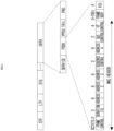
- FIG. 9 is a diagram illustrating an exemplary allocation of resource units (RUs) used on a 40 MHz band.
- 26-RU, 52-RU, 106-RU, 242-RU, 484-RU, 996-RU and the like may be used in the example of FIG. 10 as well.
- RU allocation of HE PPDUs and EHT PPDUs may be different, and the example of FIG. 10 shows an example of RU allocation for 80 MHz EHT PPDUs.
- HE PPDU 10 is the same in HE PPDU and EHT PPDU.
- EHT PPDU 23 DC tones are inserted into the DC band, and one 26-RU exists on the left and right sides of the DC band.
- one null subcarrier exists between 242-RUs rather than the center band, there are five null subcarriers in the EHT PPDU.
- one 484-RU does not include null subcarriers, but in the EHT PPDU, one 484-RU includes 5 null subcarriers.
- EHT PPDUs over 160 MHz may be configured with a plurality of 80 MHz subblocks in FIG. 10 .
- the RU allocation for each 80 MHz subblock may be the same as that of the 80 MHz EHT PPDU of FIG. 10 . If the 80 MHz subblock of the 160 MHz or 320 MHz EHT PPDU is not punctured and the entire 80 MHz subblock is used as part of RU or multiple RU (MRU), the 80 MHz subblock may use 996-RU of FIG. 10 .
- the MRU corresponds to a group of subcarriers (or tones) composed of a plurality of RUs, and the plurality of RUs constituting the MRU may be RUs having the same size or RUs having different sizes.
- a single MRU may be defined as 52+26-tone, 106+26-tone, 484+242-tone, 996+484-tone, 996+484+242-tone, 2X996+484-tone, 3X996-tone, or 3X996+484-tone.
- the 80 MHz subblock may use RU allocation other than the 996-tone RU.
- the RU of the present disclosure may be used for uplink (UL) and/or downlink (DL) communication.
- the STA transmitting the trigger e.g., AP
- trigger information e.g., trigger frame or triggered response scheduling (TRS)
- the first STA may transmit a first trigger-based (TB) PPDU based on the first RU
- the second STA may transmit a second TB PPDU based on the second RU.
- the first/second TB PPDUs may be transmitted to the AP in the same time period.
- the STA transmitting the DL MU PPDU may allocate a first RU (e.g., 26/52/106/242-RU, etc.) to a first STA and allocate a second RU (e.g., 26/52/106/242-RU, etc.) to a second STA. That is, the transmitting STA (e.g., AP) may transmit HE-STF, HE-LTF, and Data field for the first STA through the first RU and transmit HE-STF, HE-LTF, and Data field for the second STA through the second RU, in one MU PPDU,
- a first RU e.g., 26/52/106/242-RU, etc.
- a second RU e.g., 26/52/106/242-RU, etc.
- Information on the allocation of RUs may be signaled through HE-SIG-B in the HE PPDU format.
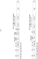
- FIG. 11 illustrates an example structure of a HE-SIG-B field.
- the HE-SIG-B field may include a common field and a user-specific field. If HE-SIG-B compression is applied (e.g., full-bandwidth MU-MIMO transmission), the common field may not be included in HE-SIG-B, and the HE-SIG-B content channel may include only a user-specific field. If HE-SIG-B compression is not applied, the common field may be included in HE-SIG-B.
- the common field may include information on RU allocation (e.g., RU assignment, RUs allocated for MU-MIMO, the number of MU-MIMO users (STAs), etc.)
- RU allocation e.g., RU assignment, RUs allocated for MU-MIMO, the number of MU-MIMO users (STAs), etc.
- the common field may include N*8 RU allocation subfields.
- One 8-bit RU allocation subfield may indicate the size (26, 52, 106, etc.) and frequency location (or RU index) of RUs included in the 20 MHz band.
- a value of the 8-bit RU allocation subfield is 00000000, it may indicate that nine 26-RUs are sequentially allocated in order from the leftmost to the rightmost in the example of FIG. 8 , if the value is 00000001, it may indicate that seven 26-RUs and one 52-RU are sequentially allocated in order from leftmost to rightest, and if the value is 00000010, it may indicate that five 26-RUs, one 52-RU, and two 26-RUs are sequentially allocated from the leftmost side to the rightmost side.
- one user/STA may be allocated to each of a plurality of RUs, and different users/STAs may be allocated to different RUs.
- a predetermined size e.g., 106, 242, 484, 996-tones, (7)
- a plurality of users/STAs may be allocated to one RU, and MU-MIMO scheme may be applied for the plurality of users/STAs.
- the set of user-specific fields includes information on how all users (STAs) of the corresponding PPDU decode their payloads.
- User-specific fields may contain zero or more user block fields.
- the non-final user block field includes two user fields (i.e., information to be used for decoding in two STAs).
- the final user block field contains one or two user fields.
- the number of user fields may be indicated by the RU allocation subfield of HE-SIG-B, the number of symbols of HE-SIG-B, or the MU-MIMO user field of HE-SIG-A.
- a User-specific field may be encoded separately from or independently of a common field.
- FIG. 12 is a diagram for explaining a MU-MIMO method in which a plurality of users/STAs are allocated to one RU.
- the user-specific field of HE-SIG-B may include 8 user fields (i.e., 4 user block fields). Eight user fields may be assigned to RUs as shown in FIG. 12 .
- the user field of the second format (i.e., the format for non-MU-MIMO allocation) may be constructed as follows. For example, out of all 21 bits of one user field, B0-B10 includes the user's identification information (e.g., STA-ID, AID, partial AID, etc.), B11-13 includes information on the number of spatial streams (NSTS) applied to the corresponding RU, B14 includes information indicating whether beamforming is performed (or whether a beamforming steering matrix is applied), B15-B18 includes Modulation and Coding Scheme (MCS) information applied to the Data field of the corresponding PPDU, B19 includes information indicating whether DCM (dual carrier modulation) is applied, and B20 may include information on a coding type (e.g., BCC or LDPC) applied to the Data field of the corresponding PPDU.
- B1-13 includes information on the number of spatial streams (NSTS) applied to the corresponding RU
- B14 includes information indicating whether beamforming is performed (or whether a beamforming steering matrix
- MCS MCS information
- MCS index MCS field, and the like used in the present disclosure may be indicated by a specific index value.
- MCS information may be indicated as index 0 to index 11.
- MCS information includes information on constellation modulation type (e.g., BPSK, QPSK, 16-QAM, 64-QAM, 256-QAM, 1024-QAM, etc.), and coding rate (e.g., 1/2, 2/ 3, 3/4, 5/6, etc.).
- coding rate e.g., 1/2, 2/ 3, 3/4, 5/6, etc.
- Information on a channel coding type e.g., BCC or LDPC
- BCC channel coding type
- FIG. 13 illustrates an example of a PPDU format to which the present disclosure may be applied.
- the EHT MU PPDU of FIG. 13 corresponds to a PPDU carrying one or more data (or PSDUs) for one or more users. That is, the EHT MU PPDU may be used for both SU transmission and MU transmission.
- the EHT MU PPDU may correspond to a PPDU for one receiving STA or a plurality of receiving STAs.
- the EHT-SIG is omitted compared to the EHT MU PPDU.
- the STA may perform UL transmission based on the EHT TB PPDU format.
- a Subcarrier frequency spacing of L-STF, L-LTF, L-SIG, RL-SIG, Universal SIGNAL (U-SIG), EHT-SIG field (these are referred to as pre-EHT modulated fields) may be set to 312.5 kHz.
- a subcarrier frequency spacing of the EHT-STF, EHT-LTF, Data, and PE field (these are referred to as EHT modulated fields) may be set to 78.125 kHz.
- the tone/subcarrier index of L-STF, L-LTF, L-SIG, RL-SIG, U-SIG, and EHT-SIG field may be indicated in units of 312.5 kHz
- the tone/subcarrier index of EHT-STF, EHT-LTF, Data, and PE field may be indicated in units of 78.125 kHz.
- the L-SIG field of FIG. 13 may be constructed with 24 bits and may be used to communicate rate and length information.
- the L-SIG field includes a 4-bit Rate field, a 1-bit Reserved bit, a 12-bit Length field, a 1-bit Parity field, and a 6-bit Tail field may be included.
- the 12-bit Length field may include information on a time duration or a length of the PPDU.
- a value of the 12-bit Length field may be determined based on the type of PPDU. For example, for a non-HT, HT, VHT, or EHT PPDU, the value of the Length field may be determined as a multiple of 3. For example, for the HE PPDU, the value of the Length field may be determined as a multiple of 3 + 1 or a multiple of 3 + 2.
- the transmitting STA may apply BCC encoding based on a coding rate of 1/2 to 24-bit information of the L-SIG field. Thereafter, the transmitting STA may obtain 48-bit BCC coded bits. BPSK modulation may be applied to 48-bit coded bits to generate 48 BPSK symbols. The transmitting STA may map 48 BPSK symbols to any location except for a pilot subcarrier (e,g,, ⁇ subcarrier index -21, -7, +7, +21 ⁇ ) and a DC subcarrier (e.g., ⁇ subcarrier index 0 ⁇ ).
- a pilot subcarrier e,g, ⁇ subcarrier index -21, -7, +7, +21 ⁇
- DC subcarrier e.g., ⁇ subcarrier index 0 ⁇
- 48 BPSK symbols may be mapped to subcarrier indices -26 to -22, -20 to -8, -6 to -1, +1 to +6, +8 to +20, and +22 to +26.
- the transmitting STA may additionally map the signals of ⁇ -1, -1, -1, 1 ⁇ to the subcarrier index ⁇ -28, -27, +27, +28 ⁇ .
- the above signal may be used for channel estimation in the frequency domain corresponding to ⁇ -28, -27, +27, +28 ⁇ .
- the transmitting STA may construct RL-SIG which is constructed identically to L-SIG.
- RL-SIG BPSK modulation is applied.
- the receiving STA may recognize that the received PPDU is a HE PPDU or an EHT PPDU based on the existence of the RL-SIG.
- the U-SIG may include N-bit information and may include information for identifying the type of EHT PPDU.
- U-SIG may be configured based on two symbols (e.g., two consecutive OFDM symbols).
- Each symbol (e.g., OFDM symbol) for the U-SIG may have a duration of 4us, and the U-SIG may have a total 8us duration.
- Each symbol of the U-SIG may be used to transmit 26 bit information.
- each symbol of the U-SIG may be transmitted and received based on 52 data tones and 4 pilot tones.
- a bit information (e.g., 52 un-coded bits) may be transmitted
- the first symbol of the U-SIG (e.g., U-SIG-1) may transmit the first X bit information (e.g., 26 un-coded bits) of the total A bit information
- the second symbol of the U-SIG (e.g., U-SIG-2) may transmit the remaining Y-bit information (e.g., 26 un-coded bits) of the total A-bit information.
- the transmitting STA may obtain 26 un-coded bits included in each U-SIG symbol.
- the A bit information (e.g., 52 un-coded bits) transmitted by the U-SIG includes a CRC field (e.g., a 4-bit field) and a tail field (e.g., 6 bit-length field).
- the CRC field and the tail field may be transmitted through the second symbol of the U-SIG.
- the CRC field may be constructed based on 26 bits allocated to the first symbol of U-SIG and 16 bits remaining except for the CRC/tail field in the second symbol, and may be constructed based on a conventional CRC calculation algorithm.
- the tail field may be used to terminate the trellis of the convolution decoder, and for example, the tail field may be set to 0.
- the version-independent bits of the U-SIG may include a 3-bit physical layer version identifier (PHY version identifier).
- the 3-bit PHY version identifier may include information related to the PHY version of the transmitted/received PPDU.
- the first value of the 3-bit PHY version identifier may indicate that the transmission/reception PPDU is an EHT PPDU.
- the transmitting STA may set the 3-bit PHY version identifier to a first value.
- the receiving STA may determine that the received PPDU is an EHT PPDU based on the PHY version identifier having the first value.
- the version-independent bits of U-SIG may include a 1-bit UL/DL flag field.
- a first value of the 1-bit UL/DL flag field is related to UL communication, and a second value of the UL/DL flag field is related to DL communication.
- EHT PPDU related to SU mode e.g., EHT PPDU related to MU mode
- EHT PPDU related to TB mode e.g., EHT PPDU related to Extended Range transmission, etc.
- information on the type of EHT PPDU may be included in the version-dependent bits of the U-SIG.
- the U-SIG may include information on 1) a bandwidth field containing information on a bandwidth, 2) a field containing information on a MCS scheme applied to EHT-SIG, 3) an indication field containing information related to whether the DCM technique is applied to the EHT-SIG, 4) a field containing information on the number of symbols used for EHT-SIG, 5) a field containing information on whether EHT-SIG is constructed over all bands, 6) a field containing information on the type of EHT-LTF/STF, and 7) a field indicating the length of EHT-LTF and CP length.
- Preamble puncturing may be applied to the PPDU of FIG. 13 .
- Preamble puncturing may mean transmission of a PPDU for which no signal is present in one or more 20 MHz subchannels among the bandwidth of the PPDU.
- Preamble puncturing may be applied to a PPDU transmitted to one or more users.
- the resolution of preamble puncturing may be 20 MHz for EHT MU PPDUs in OFDMA transmissions with bandwidths greater than 40 MHz and non-OFDMA transmissions with 80 MHz and 160 MHz bandwidths. That is, in the above case, puncturing on a subchannel smaller than 242-tone RU may not be allowed.
- the resolution of preamble puncturing may be 40 MHz. That is, puncturing for a subchannel smaller than 484-tone RU in a 320 MHz bandwidth may not be allowed. In addition, preamble puncturing may not be applied to the primary 20 MHz channel in the EHT MU PPDU.
- information on preamble puncturing may be included in the U-SIG and/or the EHT-SIG.
- the first field of the U-SIG may include information on the contiguous bandwidth of the PPDU
- the second field of the U-SIG may include information on preamble puncturing applied to the PPDU.
- the U-SIG and the EHT-SIG may include information on preamble puncturing based on the following method. If the bandwidth of the PPDU exceeds 80 MHz, the U-SIG may be individually constructed in units of 80 MHz. For example, if the bandwidth of the PPDU is 160 MHz, the PPDU may include a first U-SIG for a first 80 MHz band and a second U-SIG for a second 80 MHz band. In this case, the first field of the first U-SIG includes information on the 160 MHz bandwidth, and the second field of the first U-SIG includes information on preamble puncturing applied to the first 80 MHz band (i.e., information on a preamble puncturing pattern).
- the first field of the second U-SIG includes information on a 160 MHz bandwidth
- the second field of the second U-SIG includes information on preamble puncturing applied to a second 80 MHz band (i.e., information on a preamble puncturing pattern).
- the EHT-SIG following the first U-SIG may include information on preamble puncturing applied to the second 80 MHz band (i.e., information on a preamble puncturing pattern)
- the EHT-SIG following the second U-SIG may include information on preamble puncturing applied to the first 80 MHz band (i.e., information on a preamble puncturing pattern).
- the U-SIG and the EHT-SIG may include information on preamble puncturing based on the following method.
- the U-SIG may include information on preamble puncturing for all bands (i.e., information on a preamble puncturing pattern). That is, EHT-SIG does not include information on preamble puncturing, and only U-SIG may include information on preamble puncturing (ie, information on a preamble puncturing pattern).
- U-SIG may be constructed in units of 20 MHz. For example, if an 80 MHz PPDU is constructed, the U-SIG may be duplicated. That is, the same 4 U-SIGs may be included in the 80 MHz PPDU. PPDUs exceeding 80 MHz bandwidth may include different U-SIGs.
- the EHT-SIG of FIG. 13 may include control information for the receiving STA.
- EHT-SIG may be transmitted through at least one symbol, and one symbol may have a length of 4us.
- Information on the number of symbols used for EHT-SIG may be included in U-SIG.
- the EHT-SIG may include technical features of HE-SIG-B described through FIGS. 11 and 12 .
- EHT-SIG like the example of FIG. 8 , may include a common field and a user-specific field.
- the Common field of the EHT-SIG may be omitted, and the number of user-specific fields may be determined based on the number of users.
- the common field of the EHT-SIG and the user-specific field of the EHT-SIG may be coded separately.
- One user block field included in the user-specific field may contain information for two user fields, but the last user block field included in the user-specific field may contain one or two user fields. That is, one user block field of the EHT-SIG may contain up to two user fields.
- each user field may be related to MU-MIMO allocation or non-MU-MIMO allocation.
- the common field of the EHT-SIG may include a CRC bit and a Tail bit
- the length of the CRC bit may be determined as 4 bits
- the length of the tail bit is determined by 6 bits and may be set to 000000.
- the common field of the EHT-SIG may include RU allocation information.
- RU allocation information may mean information on the location of an RU to which a plurality of users (i.e., a plurality of receiving STAs) are allocated.
- RU allocation information may be configured in units of 9 bits (or N bits).
- a mode in which a common field of EHT-SIG is omitted may be supported.
- the mode in which the common field of the EHT-SIG is omitted may be referred as a compressed mode.
- a plurality of users (i.e., a plurality of receiving STAs) of the EHT PPDU may decode the PPDU (e.g., the data field of the PPDU) based on non-OFDMA. That is, a plurality of users of the EHT PPDU may decode a PPDU (e.g., a data field of the PPDU) received through the same frequency band.
- multiple users of the EHT PPDU may decode the PPDU (e.g., the data field of the PPDU) based on OFDMA. That is, a plurality of users of the EHT PPDU may receive the PPDU (e.g., the data field of the PPDU) through different frequency bands.
- EHT-SIG may be constructed based on various MCS scheme. As described above, information related to the MCS scheme applied to the EHT-SIG may be included in the U-SIG.
- the EHT-SIG may be constructed based on the DCM scheme.
- the DCM scheme may reuse the same signal on two subcarriers to provide an effect similar to frequency diversity, reduce interference, and improve coverage. For example, modulation symbols to which the same modulation scheme is applied may be repeatedly mapped on available tones/subcarriers.
- modulation symbols e.g., BPSK modulation symbols
- first contiguous half tones e.g., 1st to 26th tones
- modulation symbols e.g., BPSK modulation symbols
- the remaining contiguous half tones e.g., 27th to 52nd tones. That is, a modulation symbol mapped to the 1st tone and a modulation symbol mapped to the 27th tone are the same.
- the EHT-STF of FIG. 13 may be used to enhance automatic gain control (AGC) estimation in a MIMO environment or an OFDMA environment.
- the EHT-LTF of FIG. 13 may be used to estimate a channel in a MIMO environment or an OFDMA environment.
- Information on the type of STF and/or LTF may be included in the U-SIG field and/or the EHT-SIG field of FIG. 13 .
- GI guard interval
- the PPDU (i.e., EHT PPDU) of FIG. 13 may be constructed based on an example of RU allocation of FIGS. 8 to 10 .
- a EHT PPDU transmitted on a 20 MHz band may be constructed based on the RU of FIG. 8 . That is, a RU location of EHT-STF, EHT-LTF, and data field included in the EHT PPDU may be determined as shown in FIG. 8 .
- a EHT PPDU transmitted on a 40 MHz band that is, a 40 MHz EHT PPDU may be constructed based on the RU of FIG. 9 . That is, a RU location of EHT-STF, EHT-LTF, and data field included in the EHT PPDU may be determined as shown in FIG. 9 .
- the EHT PPDU transmitted on the 80 MHz band may be constructed based on the RU of FIG. 10 . That is, a RU location of EHT-STF, EHT-LTF, and data field included in the EHT PPDU may be determined as shown in FIG. 10 .
- the tone-plan for 80 MHz in FIG. 10 may correspond to two repetitions of the tone-plan for 40 MHz in FIG. 9 .
- the tone-plan for 160/240/320 MHz may be configured in the form of repeating the pattern of FIG. 9 or 10 several times.
- the PPDU of FIG. 13 may be identified as an EHT PPDU based on the following method.
- the receiving STA may determine the type of the received PPDU as the EHT PPDU based on the following. For example, when 1) the first symbol after the L-LTF signal of the received PPDU is BPSK, 2) RL-SIG in which the L-SIG of the received PPDU is repeated is detected, and 3) the result of applying the modulo 3 calculation to the value of the Length field of the L-SIG of the received PPDU (i.e., the remainder after dividing by 3) is detected as 0, the received PPDU may be determined as a EHT PPDU.
- the receiving STA may determine the type of the EHT PPDU based on bit information included in symbols subsequent to the RL-SIG of FIG. 13 . In other words, the receiving STA may determine the received PPDU as a EHT PPDU, based on 1) the first symbol after the L-LTF signal, which is BSPK, 2) RL-SIG contiguous to the L-SIG field and identical to the L-SIG, and 3) L-SIG including a Length field in which the result of applying modulo 3 is set to 0.
- the receiving STA may determine the type of the received PPDU as non-HT, HT, and VHT PPDU based on the following. For example, when 1) the first symbol after the L-LTF signal is BPSK and 2) RL-SIG in which L-SIG is repeated is not detected, the received PPDU may be determined as non-HT, HT, and VHT PPDU.
- the PPDU of FIG. 13 may be used to transmit and receive various types of frames.
- the PPDU of FIG. 13 may be used for (simultaneous) transmission and reception of one or more of a control frame, a management frame, or a data frame.
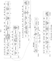
- FIG. 14 is a diagram representing an illustrative format of a trigger frame to which the present disclosure may be applied.
- a trigger frame may allocate a resource for at least one TB PPDU transmission and request TB PPDU transmission.
- a trigger frame may also include other information required by a STA which transmits a TB PPDU in response thereto.
- a trigger frame may include common information and a user information list field in a frame body.
- a common information field may include information commonly applied to at least one TB PPDU transmission requested by a trigger frame, e.g., a trigger type, a UL length, whether a subsequent trigger frame exists (e.g., More TF), whether channel sensing (CS) is required, a UL bandwidth (BW), etc.
- FIG. 14 illustratively shows a EHT variant common information field format.
- a trigger type subfield in a 4-bit size may have a value from 0 to 15.
- a value of a trigger type subfield, 0, 1, 2, 3, 4, 5, 6 and 7, is defined as corresponding to basic, Beamforming Report Poll (BFRP), multi user-block acknowledgment request (MU-BAR), multi user-request to send (MU-RTS), Buffer Status Report Poll (BSRP), groupcast with retries (GCR) MU-BAR, Bandwidth Query Report Poll (BQRP) and NDP Feedback Report Poll (NFRP) and a value of 8-15 is defined as being reserved.
- BFRP Beamforming Report Poll
- MU-BAR multi user-block acknowledgment request
- MU-RTS multi user-request to send
- BSRP Buffer Status Report Poll
- GCR groupcast with retries
- BQRP Bandwidth Query Report Poll
- NFRP NDP Feedback Report Poll
- a trigger dependent common information subfield may include information that is selectively included based on a trigger type.
- a special user information field may be included in a trigger frame.
- a special user information field does not include user-specific information, but includes extended common information which is not provided in a common information field.
- a user information list includes at least 0 user information field.
- FIG. 14 illustratively represents an EHT variant user information field format.
- a AID12 subfield is basically a user information field for a STA having a corresponding AID.
- a AID12 field may be utilized for other purpose including allocating a random access (RA)-RU or being configured in a form of a special user information field.
- a special user information field is a user information field which does not include user-specific information but includes extended common information not provided in a common information field. For example, a special user information field may be identified by an AID12 value of 2007 and a special user information field flag subfield in a common information field may represent whether a special user information field is included.
- a RU allocation subfield may represent a size and a position of a RU/a MRU.
- a RU allocation subfield may be interpreted with a PS160 (primary/secondary 160MHz) subfield of a user information field, a UL BW subfield of a common information field, etc.
- a tone plan may be related to a rule for determining the size and/or location of a resource unit (RU).
- a tone plan applied to a HE PPDU i.e., a PPDU according to the IEEE 802.1 1ax standard
- the RU size/location applied to the HE PPDU and the control information related to the RU applied to the HE PPDU are described.
- control information related to the RU may include control information onabout the size and location of the RU, information on the user STA allocated to a specific RU, a frequency bandwidth for a PPDU including the RU, and/or a modulation scheme applied to the specific RU.
- the control information related to the RU may be included in the SIG field.
- the control information related to the RU may be included in the HE-SIG-B field. That is, in the process of generating a transmission PPDU, the transmitting STA may include control information on the RU included in the PPDU in the HE-SIG-B field.
- the receiving STA may receive the HE-SIG-B included in the reception PPDU, obtain the control information included in the HE-SIG-B, determine whether there is an RU allocated to the corresponding receiving STA, and decode the allocated RU based on the HE-SIG-B.
- HE-STF In the existing wireless LAN system (e.g., IEEE 802.11ax standard), HE-STF, HE-LTF, and data fields can be configured in RU units. That is, when the first RU for the first receiving STA is configured, the STF/LTF/data fields for the first receiving STA may be transmitted and received through the first RU.
- IEEE 802.11ax standard e.g., IEEE 802.11ax standard
- a PPDU for one receiving STA i.e., SU PPDU
- a PPDU for multiple receiving STAs i.e., MU PPDU
- a tone plan for each may be defined separately.
- the RU may include multiple subcarriers.
- the RU may be expressed as an N-tone RU or N RU.
- the location of a specific RU may be indicated by a subcarrier index.
- the subcarrier index may be defined in units of subcarrier frequency spacing.
- the subcarrier frequency spacing may be 312.5 kHz or 78.125 kHz, and the subcarrier frequency spacing for the RU may be 78.125 kHz.
- the subcarrier index "+1" for the RU may mean a location that is increased by 78.125 kHz based on the DC tone
- the subcarrier index "-1" for the RU may mean a location that is decreased by 78.125 kHz based on the DC tone.
- the location of a specific RU is represented as [-121:-96]
- the RU is located in the region from subcarrier index -121 to subcarrier index -96, and as a result, the RU may include 26 subcarriers.
- the N-tone RU may include a pre-configured pilot tone.
- TB PPDU transmission corresponding to UL multi-user (MU) transmission may be possible through a trigger frame.
- the present disclosure proposes a trigger frame for TB PPDU transmission and reception in a next-generation wireless LAN system (e.g., Next 11 be, UHR, etc.) based on the trigger frame described above (e.g., related to FIG. 14 ).
- a next-generation wireless LAN system e.g., Next 11 be, UHR, etc.
- the trigger frame proposed in the present disclosure may be used to trigger/request (solocit) transmission of a TB PPDU in a next-generation wireless LAN system. Additionally or alternatively, the trigger frame proposed in the present disclosure may be used to trigger/request transmission of a TB A-PPDU.
- FIG. 15 illustrates an A-PPDU structure to which the present disclosure may be applied.
- non-legacy in the present disclosure may be applied by replacing it with a version/variant expression after the EHT version/variant (e.g., UHR).
- EHT version/variant e.g., UHR
- a trigger frame for a case where a wireless LAN system is defined to have a bandwidth of only 320 MHz (hereinafter, Embodiment 1)
- a trigger frame for a case where a wireless LAN system is defined to have a bandwidth of 480 MHz/640 MHz are described (hereinafter, Embodiment 2).
- Each subfield of the non-legacy variant common info field may be as follows.
- the LDPC Extra Segment subfield may be defined as in Fig. 14 .
- B54 and B55 in the non-legacy variant common info field can be used to distinguish which TB PPDU the corresponding non-legacy trigger frame triggers/requests.
- B54 in the legacy variant common info field (e.g., EHT variant common info field), B54 may correspond to the HE/EHT P160 subfield, and B55 may be a Special User Info Field Flag subfield.
- At least one specific bit included in the non-legacy variant common info field may be defined as an A-PPDU Flag subfield, and the subfield may be used to indicate an A-PPDU. Additionally, the subfield may be named as a non-legacy (i.e., next version) P160 subfield, or another name may be used.
- the subfield may be set to a value of 0 to indicate that the TB PPDU triggered/requested by the trigger frame corresponds to an A-PPDU, and the subfield may be set to a value of 1 to indicate that the TB PPDU triggered/requested by the trigger frame does not correspond to an A-PPDU.
- one of the bits B22, B26, and B53 may be used as an example of another reserved bit.
- B22, B26, and B53 it may be desirable not to use B22, B26, and B53 in terms of an information transmission error that may occur to a legacy STA (e.g., HE STA).
- B56 to B62 in the non-legacy variant common info field may be changed to non-legacy (i.e., next version) reserved subfields.
- some bits of B56 to B62 in the variant common info field may be defined as specific subfields, and the remaining bits may be changed to non-legacy (i.e., next version) reserved subfields.
- B63 within the non-legacy variant common info field may be a reserved field.
- the last row in that table enables a non-AP EHT STA to transmit a HE TB PPDU on the primary 160 MHz in response to a trigger frame containing a special user information field.
- various TB PPDUs may be triggered/requested through the trigger frame defined in FIG. 14 .
- HE TB PPDU, EHT TB PPDU, and P160 HE TB PPDU + S160 EHT TB PPDU can be triggered/requested through the trigger frame.
- P160 HE TB PPDU and S160 EHT TB PPDU represent HE TB PPDU in primary 160 MHz bandwidth and EHT TB PPDU in secondary 160 MHz bandwidth, respectively.
- the bandwidth actually used in P160 and S160 may be less than or equal to 160 MHz.
- PPDUs transmitted using B54, B55, and B39 of the user information field may be distinguished.
- the non-legacy trigger frame (i.e., the trigger frame in the next version) proposed in the present disclosure may be defined/configured to trigger/request not only the HE TB PPDU, EHT TB PPDU, and P160 HE TB PPDU + S160 EHT TB PPDU in the examples described above, but also additionally the non-legacy (i.e., next version) TB PPDU, P160 HE TB PPDU + S160 non-legacy TB PPDU, and P160 EHT TB PPDU + S160 non-legacy TB PPDU.
- the bandwidth actually used in P160 and S160 may be less than or equal to 160 MHz.
- the B54, B55, and A-PPDU flag subfields may be used to distinguish and trigger/request different TB PPDUs through non-legacy trigger frames. Additionally, the user info field variant and the allocated PPDU may be distinguished using B39 of the user info field.
- a bit setting method for each TB PPDU configuration is proposed when triggering TB PPDU/TB A-PPDU based on a non-legacy trigger frame.
- B54 may be set to the value 1
- B55 may be set to the value 1
- the A-PPDU flag subfield may be set to the value 1.
- B54 may be set to 0, B55 may be set to 0, and the A-PPDU Flags subfield may be set to 1. Additionally, the PHY version identifier subfield in the special user info field (e.g., EHT Variant Special User Info field) may indicate EHT.
- EHT Variant Special User Info field e.g., EHT Variant Special User Info field
- B54 is set to 1 value
- B55 is set to 0 value
- A-PPDU Flags subfield may be set to 1 value or 0 value.
- the PHY version identifier subfield in the special user info field e.g., EHT Variant Special User Information field
- EHT Variant Special User Information field may indicate EHT.
- variants of the user info field may be distinguished using B39 of the user info field, and B39 set to a value of 0 may indicate a HE variant, and B39 set to a value of 1 may indicate an EHT variant.
- the aforementioned TB PPDU configuration when decoding the trigger frame, (any) non-legacy (i.e., next version) STA may interpret it as a legacy trigger frame (e.g., the trigger frame in FIG. 14 ). In this case, the aforementioned TB PPDU configuration may not be a problem since it is not related to a non-legacy TB PPDU.
- B54 may be set to 0, B55 may be set to 1, and the A-PPDU flag subfield may be set to 1.
- non-legacy STA may interpret it as a non-legacy trigger frame (i.e., enhanced trigger frame).
- This method may be desirable from the perspective of power saving of legacy STAs (e.g., EHT STAs).
- legacy STAs e.g., EHT STAs.
- B54 may be set to 0 value
- B55 may be set to 1 value
- A-PPDU Flag subfield may be set to 0 value.
- non-legacy variant special user info field may exist.
- This setting is identical to a method of triggering the aforementioned P160 HE TB PPDU + S160 EHT TB PPDU, but may be distinguished using the PHY version identifier subfield of the special user info field.
- This method may require additional time for a non-legacy STA to recognize that the P160 HE TB PPDU + S160 non-legacy TB PPDU is a trigger frame, but has the advantage of reducing complexity while maintaining the existing design method.
- an EHT STA may be assigned to a HE TB PPDU and perform transmission, but an error may occur depending on the implementation because the EHT variant special user info field does not exist.
- non-legacy variant special user info field may exist.
- B54 may be set to 0 value
- B55 may be set to 0 value
- A-PPDU Flags subfield may be set to 0 value.
- EHT STA may interpret that the trigger frame triggers EHT TB PPDU on all channels. In this regard, since only non-legacy STAs will be allocated for S160, such interpretation may not be a problem.
- bit settings for triggering/indicating each TB PPDU configuration may be a preferable method.
- Table 2 Bit setting HE TB PPDU B54: 1, B55: 1, A-PPDU flag: 1 EHT TB PPDU B54: 0, B55: 0, A-PPDU flag: 1 P160 HE TB PPDU + S160 EHT TB PPDU B54: 1, B55: 0, A-PPDU flag: 1 non-legacy TB PPDU B54: 0, B55: 1, A-PPDU flag: 1 P160 HE TB PPDU + S160 non-legacy TB PPDU B54: 1, B55: 1, A-PPDU flag: 0 P160 EHT TB PPDU + S160 non-legacy TB PPDU B54: 0, B55: 0, A-PPDU flag: 0 P160 EHT TB PPDU + S160 non-legacy TB PPDU B54: 0, B55: 0, A-PPDU flag: 0
- B55 set to a value of 1 may indicate that the EHT variant special user info field does not exist, and B55 set to a value of 0 may indicate that the EHT variant special user info field exists.
- B55 may not be related to the existence of a non-legacy variant special user info field (e.g., a UHR variant special user info field). That is, in a next-generation wireless LAN system (e.g., a next version of a WiFi system), the meaning of B55 may have the same meaning as EHT.
- Non-legacy TB PPDU or an A-PPDU including a non-legacy TB PPDU may be transmitted in the non-legacy variant common info field and the non-legacy variant special user info field. Additionally, whether the non-legacy variant special user info field exists may be indicated in the non-legacy variant common info field.
- the subfield may consist of one bit (e.g., B57) from among B56 to B62 of the non-legacy variant common info field, excluding the A-PPDU flag subfield.
- the subfield set to a value of 0 may indicate that the non-legacy variant special user info field exists, and the subfield set to a value of 1 may indicate that the non-legacy variant special user info field does not exist.
- B22, B26, or B53 may be used, but when considering A-PPDU, an information transmission error may occur to the HE STA, and therefore it may be desirable not to use B22, B26, or B53.
- the non-legacy variant special user info field flag subfield may be unnecessary. Since a non-legacy STA may distinguish TB PPDUs triggered by the B54, B55 and A-PPDU flag subfields, it may determine the presence of the non-legacy variant special user info field using only that information (i.e., implicit indication).
- Non-legacy variant special user info fields may be defined based on a legacy special user info field (e.g., a special user info field in FIG. 14 ).
- the non-legacy variant special user info field may be used to indicate information of a non-legacy TB PPDU.
- the non-legacy variant special user info field may also indicate information of an EHT TB PPDU.
- the field may be located after the non-legacy common info field. If a legacy special user info field (e.g., EHT variant special user info field) exists in the trigger frame, the legacy special user info field may be located after the non-legacy common info field, and then the non-legacy variant special user info field may be located thereafter.
- a legacy special user info field e.g., EHT variant special user info field
- Each subfield of the non-legacy variant special user info field may be as follows.
- the AID12 subfield may be set to a value such as 2007 (same as the existing value) or 2008.
- the PHY version identifier subfield may indicate non-legacy (i.e., next version).
- the UL bandwidth extension subfield may indicate up to 320 MHz bandwidth together with the UL BW subfield, and may also indicate additional bandwidth using reserved values.
- EHT Spatial Reuse 1/2 subfield may be renamed to the non-legacy Spatial Reuse 1/2 subfield and defined in the same way as before.
- the U-SIG Disregard And Validate subfield may be set to a value that applies to the setting of the value of the U-SIG Disregard / Validate field of the non-legacy TB PPDU.
- the Disregard / Validate field defined in the (actual) non-legacy TB PPDU only some bits may be used, or some or all bits of the reserved subfields of B37 to B39 may be additionally used.
- both the EHT variant special user info field and the non-legacy variant special user info field may be present.
- the contents are nearly identical, only the non-legacy variant special user info field may be present.
- the AID12 subfield shall be set to 2007, and the EHT STA may interpret the non-legacy variant special user info field as if it were an EHT variant special user info field based on the legacy definition.
- the non-legacy STA may interpret the non-legacy variant special user info field based on the new definition.
- the non-legacy variant user info field may be used to indicate information of a user assigned to a non-legacy TB PPDU transmission.
- the non-legacy variant user info field may be located after the non-legacy variant special user info field. If a legacy user info field (e.g., HE/EHT variant user info field) exists in the trigger frame, the legacy user info field (e.g., HE/EHT variant user info field) may be located after the non-legacy variant special user info field, and the non-legacy variant user info field may be located thereafter.
- a legacy user info field e.g., HE/EHT variant user info field
- the legacy user info field e.g., HE/EHT variant user info field
- the non-legacy variant user info field may be located thereafter.
- Each subfield of the non-legacy variant user info field may be as follows.
- the AID12 subfield may indicate the AID of a non-legacy STA.
- the RU allocation subfield indicates RU allocation information, and the definition of the existing RU allocation subfield may be used as is, or some RU allocation information may be changed/added/excluded.
- the UL FEC coding type subfield may be defined in the same way as before.
- the UL EHT-MCS subfield may be renamed to UL non-legacy-MCS subfield (a different name may be used), defined in the same way as before, or some MCS may be changed/added/excluded.
- reserved subfields may be maintained in the same manner as before.
- the SS allocation subfield may be defined in the same way as before, or alternatively, up to 16 additional streams may be indicated.
- the RA-RU information subfield and the UL target reception power subfield may be defined in the same manner as in the existing manner.
- the PS160 subfield may be used to indicate RU allocation information together with the RU allocation subfield.
- the subfield may indicate information on whether the RU is within P160 or within S160.
- variant information of the user info field may be indicated in the case of A-PPDU.
- This embodiment is for non-legacy trigger frames defined up to 480 MHz or 640 MHz bandwidth/channel width.
- Next-generation wireless LAN systems may be defined to have bandwidths of up to 480 MHz or 640 MHz. Taking this into account, additional subfields, etc. may be defined as described in this embodiment, and the subfields may be used for bandwidth indication and PPDU/user information field variant differentiation.
- a method of indicating a bandwidth of up to 320 MHz is defined using the UL BW subfield of the EHT variant common info field and the UL BW extension subfield of the special user info field, and some combinations of values among them are reserved.
- a bandwidth of up to 320 MHz may be indicated using the same method as described above. Additionally, a specific reserved value may be used to indicate a wider bandwidth.
- a bandwidth of up to 320 MHz may be indicated by using the same combination of values as before, using the UL BW subfield of the non-legacy variant common info field and the UL BW extension subfield of the non-legacy variant special user info field.
- a wider bandwidth may be indicated by using the following combinations of various reserved bits.
- the UL BW subfield may be set to values 0 / 1 / 2, and the UL BW extension subfield may be set to value 1.
- the UL BW subfield may be set to values 0 / 1 / 2
- the UL BW extension subfield may be set to value 2.
- other combinations of values may follow the existing indication method.
- the UL BW subfield may be set to values 0 / 1 / 2, and the UL BW extension subfield may be set to value 1.
- the UL BW subfield may be set to values 0 / 1 / 2
- the UL BW extension subfield may be set to value 2.
- the UL BW subfield may be set to values 0 / 1 / 2
- the UL BW extension subfield may be set to value 3.
- other combinations of values may follow the existing indication method.
- the UL BW subfield may be set to the value 0 / 1, and the UL BW extension subfield may be set to the value 1.
- the UL BW subfield may be set to the value 1 / 2
- the UL BW extension subfield may be set to the value 1.
- other combinations of values may follow the existing indication method.
- the UL BW subfield may be set to the value 0 / 1, and the UL BW Extension subfield may be set to the value 1.
- the UL BW subfield may be set to the value 1 / 2
- the UL BW Extension subfield may be set to the value 1.
- the UL BW subfield may be set to the value 1 / 2
- the UL BW Extension subfield may be set to the value 2.
- other combinations of values may follow the existing indication method.
- the UL BW subfield may be set to a value of 0 / 1, and the UL BW Extension subfield may be set to a value of 1.
- the UL BW subfield may be set to a value of 1 / 2
- the UL BW Extension subfield may be set to a value of 1.
- the UL BW subfield may be set to a value of 1 / 2
- the UL BW Extension subfield may be set to a value of 2.
- the UL BW subfield may be set to a value of 1 / 2
- the UL BW Extension subfield may be set to a value of 3.
- other combinations of values may follow the existing indication method.
- the UL BW subfield may be set to a value of 0 / 1, and the UL BW extension subfield may be set to a value of 1.
- the UL BW subfield may be set to a value of 0 / 1
- the UL BW extension subfield may be set to a value of 2.
- the UL BW subfield may be set to a value of 1 / 2
- the UL BW extension subfield may be set to a value of 1.
- the UL BW subfield may be set to a value of 1 / 2
- the UL BW extension subfield may be set to a value of 2.
- other combinations of values may follow the existing indication method.
- the UL BW subfield may be set to a value of 0 / 1, and the UL BW extension subfield may be set to a value of 1.
- the UL BW subfield may be set to a value of 0 / 1
- the UL BW extension subfield may be set to a value of 2.
- the UL BW subfield may be set to a value of 1 / 2
- the UL BW extension subfield may be set to a value of 1.
- the UL BW subfield may be set to a value of 1 / 2, and the UL BW extension subfield may be set to a value of 2.
- the UL BW subfield may be set to a value of 1 / 2
- the UL BW extension subfield may be set to a value of 3.
- other combinations of values can follow the existing directives.
- the UL BW subfield may be set to a value of 0 / 1, and the UL BW Extension subfield may be set to a value of 1.
- the UL BW subfield may be set to a value of 0 / 1
- the UL BW Extension subfield may be set to a value of 2.
- the UL BW subfield may be set to a value of 0 / 1
- the UL BW Extension subfield may be set to a value of 3.
- the UL BW subfield may be set to a value of 1 / 2
- the UL BW Extension subfield may be set to a value of 1.
- other combinations of values may follow the existing indication method.
- the UL BW subfield may be set to a value of 0 / 1, and the UL BW extension subfield may be set to a value of 1.
- the UL BW subfield may be set to a value of 0 / 1
- the UL BW extension subfield may be set to a value of 2.
- the UL BW subfield may be set to a value of 0 / 1
- the UL BW extension subfield may be set to a value of 3.
- the UL BW subfield may be set to a value of 1 / 2, and the UL BW extension subfield may be set to a value of 1.
- the UL BW subfield may be set to a value of 1 / 2
- the UL BW extension subfield may be set to a value of 2.
- other combinations of values can follow the existing directives.
- the UL BW subfield may be set to a value of 0 / 1, and the UL BW extension subfield may be set to a value of 1.
- the UL BW subfield may be set to a value of 0 / 1
- the UL BW extension subfield may be set to a value of 2.
- the UL BW subfield may be set to a value of 0 / 1
- the UL BW extension subfield may be set to a value of 3.
- the UL BW subfield may be set to a value of 1 / 2, and the UL BW extension subfield may be set to a value of 1.
- the UL BW subfield may be set to a value of 1 / 2
- the UL BW extension subfield may be set to a value of 2.
- the UL BW subfield may be set to the value 1/2
- the UL BW Extension subfield may be set to the value 3.
- other combinations of values may follow the existing indication method.
- the UL BW subfield may be set to the values 0 / 1 / 2, and the UL BW Extension subfield may be set to the value 1.
- other combinations of values may follow the existing indication method.
- the UL BW subfield may be set to values 0 / 1 /2, and the UL BW extension subfield may be set to value 1.
- the UL BW subfield may be set to values 0 / 1 /2, and the UL BW extension subfield may be set to value 2.
- other combinations of values may follow the existing indication method.
- the UL BW subfield may be set to values 0 / 1 /2, and the UL BW extension subfield may be set to value 1.
- the UL BW subfield may be set to values 0 / 1 /2, and the UL BW extension subfield may be set to value 2.
- the UL BW subfield may be set to values 0 / 1 /2, and the UL BW extension subfield may be set to value 3.
- other combinations of values may follow the existing indication method.
- the UL BW subfield may be set to the values 0 / 1 /2, and the UL BW Extension subfield may be set to the value 1.
- other combinations of values may follow the existing indication method.
- the UL BW subfield may be set to values 0 / 1 /2, and the UL BW extension subfield may be set to value 1.
- the UL BW subfield may be set to values 0 / 1 /2, and the UL BW extension subfield may be set to value 2.
- other combinations of values may follow the existing indication method.
- the UL BW subfield may be set to values 0 / 1 /2, and the UL BW extension subfield may be set to value 1.
- the UL BW subfield may be set to values 0 / 1 /2, and the UL BW extension subfield may be set to value 2.
- the UL BW subfield may be set to values 0 / 1 /2, and the UL BW extension subfield may be set to value 3.
- other combinations of values may follow the existing indication method.
- a method may be considered to indicate additional bandwidth by using one or more bits corresponding to reserved subfields of the existing special user information field in the non-legacy variant special user information field (e.g., B37 to B39).
- the UL BW subfield of the non-legacy variant common info field and the UL BW extension subfield of the non-legacy variant special user info field may use the existing indication method.
- bandwidth When indicating bandwidth using the corresponding bits (e.g., B37 to B39), the bandwidth may be indicated independently. Alternatively, in this case, additional bandwidth may be indicated using a combination of the values of the UL BW subfield, the UL BW extension subfield, and the corresponding bit values, as in the existing method.
- non-legacy special user info fields may exist when triggering TB A-PPDU of EHT TB PPDU and non-legacy TB PPDU.
- EHT STA may interpret non-legacy special user info field as existing special user info field.
- non-legacy STA may interpret non-legacy special user info field according to newly defined method.
- the method may simultaneously indicate the bandwidth of EHT TB PPDU and non-legacy TB PPDU.
- the PHY version identifier subfield needs to be set to EHT, but non-legacy STA may interpret based on the new definition.
- non-legacy STA may be assigned to the EHT TB PPDU part, both interpretations need to be possible, which may increase the implementation complexity.
- the method of triggering/indicating the TB PPDU configuration in the aforementioned embodiment 1 may be used.
- bit combinations described below may be considered to indicate specific channels in various situations considering wider bandwidths (i.e. 480MHz/640MHz bandwidth).
- the RU allocation subfield of the non-legacy variant user info field may indicate RU allocation information within a 160MHz unit.
- the subfield may exceptionally indicate some large RUs/MRUs corresponding to channels exceeding 160MHz. Therefore, with respect to a specific channel indication, a method of indicating at least a 160MHz channel may be considered.
- non-legacy TB PPDU bandwidth indication may be performed using the UL BW subfield in the non-legacy variant common info field and the UL BW extension subfield and additional BW subfield (if present) in the non-legacy variant special user info field. That is, the bandwidth indication method described above may be used.
- indication up to 640 MHz may be possible.
- 160 and 320 may mean a 160 MHz band/channel and a 320 MHz band/channel, respectively. Additionally, lower 160/320 and higher 160/320 may mean 160/320 existing in a relatively low band in the frequency domain and 160/320 existing in a relatively high band in the frequency domain, respectively.
- a value of 0 in B25 may indicate P320 (or lower 320), and a value of 1 in B25 may indicate S320 (or higher 320).
- the combination of 0 value of B25 and 0 value of B39 may indicate P160.
- the combination of 0 value of B25 and 0 value of B39 may indicate lower 160 at P320, or lower 160 at lower 320, which may not be desirable when considering unification with other cases.
- a combination of 0 value of B25 and 1 value of B39 can indicate S160.
- a combination of 0 value of B25 and 1 value of B39 may indicate higher 160 at P320, or lower 320 to higher 160, which may not be desirable when considering integration with other cases.
- a combination of a 1 value of B25 and a 0 value of B39 may indicate 160 corresponding to the position of P160 in S320.
- a combination of a 1 value of B25 and a 0 value of B39 may indicate a lower 160 in S320, or a lower 160 in higher 320, the latter of which may not be desirable when considering integration with other cases.
- a combination of a 1 value of B25 and a 1 value of B39 may indicate 160 corresponding to a position of S160 in S320.
- a combination of a 1 value of B25 and a 1 value of B39 may indicate a higher 160 in S320, or a higher 160 in higher 320, the latter of which may not be desirable when considering integration with other cases.
- SS160 may mean the remaining 160MHz channel excluding P320 when transmitting at 480MHz.
- a combination of a 0 value of B25 and a 0 value of B39 may indicate P160.
- a combination of a 0 value of B25 and a 1 value of B39 may indicate S160.
- a combination of a 1 value of B25 and a 1 value (or a 0 value) of B39 may indicate SS160.
- a combination of a 1 value of B25 and a 0 value of B39 may be reserved.
- 0/1 value of B25 and 0 value of B39 may indicate P160.
- 0 value of B25 and 1 value of B39 may indicate S160.
- 1 value of B25 and 1 value of B39 may indicate SS160.
- a combination of a 0 value of B25 and a 0 value (or a 1 value) of B39 may indicate P160.
- a combination of a 0 value of B25 and a 1 value of B39 may be reserved.
- a combination of a 1 value of B25 and a 0 value of B39 may indicate 160 (or a lower 160 in S320) corresponding to a position of P160 in S320.
- a combination of a 1 value of B25 and a 1 value of B39 may indicate 160 (or a higher 160 in S320) corresponding to a position of S160 in S320.
- 0/1 value of B25 and 0 value of B39 may indicate P160.
- 0 value of B25 and 1 value of B39 may indicate 160 (or lower 160 in S320) corresponding to position of P160 in S320.
- a combination of 1 value of B25 and 1 value of B39 may indicate 160 (or higher 160 in S320) corresponding to position of S160 in S320.
- B54 of the non-legacy variant common info field may be set to 0, B55 may be set to 1, and the A-PPDU Flag subfield may be set to 0.
- B54 of the non-legacy variant common info field may be set to 1 value
- B55 may be set to 0 value
- A-PPDU Flags subfield may be set to 0 / 1 value
- PHY version identifier subfield in the special user info field (e.g., non-legacy special user info field) may be set to indicate non-legacy.
- the UL BW subfield within the non-legacy variant common info field may indicate 160 MHz
- A-PPDU bandwidth and non-legacy TB PPDU bandwidth indication may be performed using the UL BW subfield in the non-legacy variant common info field and the UL BW extension subfield and additional BW subfield (if present) in the non-legacy variant special user info field.
- TB A-PPDU at 640MHz may not be possible.
- B25 in the HE Variant User Info field is used as a DCM field with values of 0/1, and B39 is used when it is 0. That is, channel indication using a combination of 1 value of B25 and 0 value of B39 is not possible.
- channels, PPDUs and user info field variants may be distinguished using B39 of the user info field, and channels may be distinguished using B25 when B39 is set to a value of 1.
- a value of 0 in B39 may indicate P160, which may indicate a HE variant user info field (B25 may be a value of 0 or a value of 1).
- a value of 1 in B39 may indicate S160 or SS160, which may indicate a non-legacy variant user info field.
- a combination of a value of 0 in B25 and a value of 1 in B39 may indicate S160, and a combination of a value of 1 in B25 and a value of 1 in B39 may indicate SS160.
- channels, PPDUs and user info field variants may be distinguished using B39 of the user info field, and channels may be distinguished using B25 when B39 is set to a value of 1.
- a value of 0 of B39 may indicate P160, which may indicate a HE variant user info field (B25 may be a value of 0 or a value of 1).
- a value of 1 of B39 may indicate S320 or SS160, which may indicate a non-legacy variant user info field.
- a combination of a value of 0 of B25 and a value of 1 of B39 may indicate 160 (or a lower 160 in S320) corresponding to the position of P160 in S320.
- a combination of a value of 1 of B25 and a value of 1 of B39 may indicate 160 (or a higher 160 in S320) corresponding to the position of S160 in S320.
- B54 of the non-legacy variant common info field may be set to 0 value
- B55 may be set to 0 value
- A-PPDU flag subfield may be set to 0 value
- 320MHz indication may be performed in the UL BW subfield within the non-legacy variant common info field and the UL BW extension subfield within the special user info field (or the non-legacy variant special user info field).
- A-PPDU bandwidth and non-legacy TB PPDU bandwidth indication may be performed using the UL BW subfield in the non-legacy variant common info field and the UL BW extension subfield and additional BW subfield (if present) in the non-legacy variant special user info field.
- B25 in the EHT variant user info field is a reserved bit, it is possible to use B25 and B39 in the user info field to indicate channel positions up to 640 MHz.
- the channel, PPDU and user info field variants may be distinguished using the combination of B25 and B39 of the user information field.
- EHT STA may determine only using B39, and non-legacy STA will be allocated only to S320, so there may be no problem.
- a combination of a 0 value of B25 and a 0 value of B39 indicates P160, which may indicate an EHT variant user info field.
- a combination of a 0 value of B25 and a 1 value of B39 indicates S160, which may indicate an EHT variant user info field.
- a combination of a 1 value of B25 and a 0 value of B39 indicates 160 (or a lower 160 in S320) corresponding to the position of P160 in S320, which may indicate a non-legacy variant user info field.
- a combination of a 1 value of B25 and a 1 value of B39 indicates 160 (or a higher 160 in S320) corresponding to the position of S160 in S320, which may indicate a non-legacy variant user info field.
- 0/1 value of B25 and 0 value of B39 may indicate P160, which may indicate EHT variant user info field.
- 0 value of B25 and 1 value of B39 may indicate S160, which may indicate EHT variant user info field.
- a combination of 1 value of B25 and 1 value of B39 may indicate SS160, which may indicate non-legacy variant user info field.
- B54 of the non-legacy variant common information field may be set to 0 value
- B55 may be set to 0 value
- the A-PPDU Flag subfield may be set to 0 value.
- A-PPDU bandwidth and non-legacy TB PPDU bandwidth indication may be performed using the UL BW subfield in the non-legacy variant common info field and the UL BW extension subfield and additional BW subfield (if present) in the non-legacy variant special user info field.
- B25 in the EHT variant user info field is a reserved bit, it is possible to use B25 and B39 in the user info field to indicate channel positions up to 640 MHz.
- the channel, PPDU and user info field variants may be distinguished using the combination of B25 and B39 of the user info field.
- EHT STA may determine only using B39, and non-legacy STA will be allocated only to S160 and S320, so there may be no problem.
- a combination of a 0 value of B25 and a 0 value of B39 may indicate P160, which may indicate an EHT variant user info field.
- a combination of a 0 value of B25 and a 1 value of B39 may indicate S160, which may indicate a non-legacy variant user info field.
- a combination of a 1 value of B25 and a 0 value of B39 may indicate 160 (or a lower 160 in S320) corresponding to the position of P160 in S320, which may indicate a non-legacy variant user info field.
- a combination of a 1 value of B25 and a 1 value of B39 may indicate 160 (or a higher 160 in S320) corresponding to the position of S160 in S320, which may indicate a non-legacy variant user info field.
- the channel, PPDU, and user info field variants may be distinguished using the combination of B25 and B39 of the user info field.
- EHT STA may determine only using B39, and non-legacy STA will be allocated only to S160, SS160, so there may be no problem.
- a combination of 0 value of B25 and 0 value of B39 may indicate P160, which may indicate an EHT variant user info field.
- a combination of 0 value of B25 and 1 value of B39 may indicate S160, which may indicate a non-legacy variant user info field.
- a combination of 1 value of B25 and 1 value (or 0 value) of B39 may indicate SS160, which may indicate a non-legacy variant user info field.
- a combination of 1 value of B25 and 0 value of B39 may be reserved.
- 0/1 value of B25 and 0 value of B39 may indicate P160, which may indicate EHT variant user info field.
- 0 value of B25 and 1 value of B39 may indicate S160, which may indicate non-legacy variant user info field.
- a combination of 1 value of B25 and 1 value of B39 may indicate SS160, which may indicate non-legacy variant user info field.
- the channel, PPDU and user info field variants may be distinguished using the combination of B25 and B39 of the user info field.
- EHT STA may determie only using B39, and non-legacy STA will be allocated only to S320, so there may be no problem.
- a combination of a 0 value of B25 and a 0 value of B39 indicates P160, which may indicate an EHT variant user info field.
- a combination of a 0 value of B25 and a 1 value of B39 is reserved, and may indicate a non-legacy variant user info field.
- a combination of a 1 value of B25 and a 0 value of B39 indicates 160 (or a lower 160 in S320) corresponding to a position of P160 in S320, and may indicate a non-legacy variant user info field.
- a combination of a 1 value of B25 and a 1 value of B39 indicates 160 (or a higher 160 in S320) corresponding to a position of S160 in S320, and may indicate a non-legacy variant user info field.
- 0/1 value of B25 and 0 value of B39 may indicate P160, which may indicate an EHT variant user info field.
- 0 value of B25 and 1 value of B39 may indicate 160 (or lower 160 in S320) corresponding to the position of P160 in S320, which may indicate a non-legacy variant user info field.
- a combination of 1 value of B25 and 1 value of B39 may indicate 160 (or higher 160 in S320) corresponding to the position of S160 in S320, which may indicate a non-legacy variant user info field.
- B54 of the non-legacy variant common info field may be set to 1
- B55 may be set to 0
- the A-PPDU Flag subfield may be set to 0.
- the UL BW subfield within the non-legacy variant common info field may indicate 160 MHz.
- 320MHz indication or EHT TB PPDU bandwidth (160MHz) indication may be performed in the UL BW subfield in the non-legacy variant common info field and the UL BW extension subfield in the special user info field (or the non-legacy variant special user info field).
- TB A-PPDU at 640MHz may not be possible.
- B25 in the HE Variant User Info field is used as a DCM field with values of 0/1, and B39 is used when it is 0. That is, channel indication using a combination of 1 value of B25 and 0 value of B39 is not possible.
- the channel, PPDU and user info field variants may be distinguished using the combination of B25 and B39 of the user information field.
- EHT STA may determine only using B39, and non-legacy STA will be allocated only to SS160, so there may be no problem.
- a combination of 0/1 value of B25 and 0 value of B39 may indicate P160, which may indicate an HE variant user info field.
- a combination of 0 value of B25 and 1 value of B39 may indicate S160, which may indicate an EHT variant user info field.
- a combination of 1 value of B25 and 1 value of B39 may indicate SS160, which may indicate a non-legacy variant user info field.
- P160 + S320 may not be considered.
- the case may be the same as the P160 HE TB PPDU + S320 non-legacy TB PPDU case.
- FIG. 16 is a flowchart for illustrating the operation of an STA based on a trigger frame according to the present disclosure.
- the STA may receive a trigger frame including a common info field from an access point (AP).
- AP access point
- the STA may correspond to a non-AP STA.
- the STA may receive a trigger frame asssociated with a trigger of a non-legacy TB PPDU (e.g., a TB PPDU of a subsequent version of EHT).
- the trigger frame may include a non-legacy common info field.
- the common info field may include aggregated PPDU (A-PPDU) related subfields.
- A-PPDU aggregated PPDU
- a value of 0 in the A-PPDU related subfield indicates an A-PPDU containing a non-legacy TB PPDU
- a value of 1 in the A-PPDU related subfield may include at least one of a non-A-PPDU or an A-PPDU that does not contain a non-legacy TB PPDU (i.e., an A-PPDU constructed with only of legacy TB PPDUs).
- the STA may transmit to the AP a TB PPDU corresponding to one of one or more TB PPDUs triggered/requested by the trigger frame.
- the configuration of one or more TB PPDUs may be indicated based on the A-PPDU related subfields and at least one other subfield included in the common info field.
- the at least one other subfield may include B45 bits and B55 bits within the common info field.
- a value of 1 of B54 may indicate that the primary 160 MHz channel is allocated to a HE (high efficiency) TB PPDU, and a value of 0 of B54 may indicate that the primary 160 MHz channel is allocated to an EHT (extremely high throughput) TB PPDU or a non-legacy TB PPDU.
- the 0 and 1 values of the above B55 may be associated with the presence of a non-legacy variant special user info field (e.g., flag information).
- a non-legacy variant special user info field e.g., flag information
- the one or more TB PPDUs may correspond to a HE (high efficiency) TB PPDU. That is, in this case, the trigger frame in step S1610 may be a trigger frame that triggers/requests a HE TB PPDU.
- the one or more TB PPDUs may correspond to an EHT (extremely high throughput) TB PPDU. That is, in this case, the trigger frame in step S1610 may be a trigger frame that triggers/requests an EHT TB PPDU.
- the one or more TB PPDUs may correspond to HE TB PPDU and EHT TB PPDU. That is, in this case, the trigger frame in step S1610 may be a trigger frame that triggers/requests HE TB PPDU and EHT TB PPDU (e.g., an ssA-PPDU constructed with P160 HE TB PPDU + S160 EHT TB PPDU).
- the trigger frame in step S1610 may be a trigger frame that triggers/requests HE TB PPDU and EHT TB PPDU (e.g., an ssA-PPDU constructed with P160 HE TB PPDU + S160 EHT TB PPDU).
- the one or more TB PPDUs may correspond to non-legacy TB PPDUs. That is, in this case, the trigger frame in step S1610 may be a trigger frame that triggers/requests a non-legacy TB PPDU (e.g., a TB PPDU of a version following EHT).
- a non-legacy TB PPDU e.g., a TB PPDU of a version following EHT.
- the one or more TB PPDUs may correspond to a HE TB PPDU and a non-legacy TB PPDU. That is, in this case, the trigger frame in step S1610 may be a trigger frame that triggers/requests a HE TB PPDU and a non-legacy TB PPDU (e.g., an A-PPDU constructed with a P160 HE TB PPDU + a S160 non-legacy TB PPDU).
- the one or more TB PPDUs may correspond to an EHT TB PPDU and a non-legacy TB PPDU. That is, in this case, the trigger frame in step S1610 may be a trigger frame that triggers/requests an EHT TB PPDU and a non-legacy TB PPDU (e.g., an A-PPDU constructed with a P160 EHT TB PPDU + a S160 non-legacy TB PPDU).
- whether a non-legacy variant special user info field is present in the trigger frame in step S1610 may be (implicitly) indicated based on at least one other subfield included in the A-PPDU related subfield and the common info field.
- the trigger frame in step S1610 may include at least one of a special user info field (e.g., a non-legacy variant special user info field) related to information on a non-legacy TB PPDU or a user info field (e.g., a non-legacy variant user info field) related to information on an STA allocated to transmission of the non-legacy TB PPDU.
- a special user info field e.g., a non-legacy variant special user info field
- a user info field e.g., a non-legacy variant user info field
- the channel indication for the non-legacy TB PPDU may be based on a combination of a value of B25 and a value of B39 in the user info field.
- the method performed by the STA described in the example of FIG. 16 may be performed by the first device (100) of FIG. 1 .
- one or more processors (102) of the first device (100) of FIG. 1 may be configured to receive a trigger frame including a common info field from the AP (200) through one or more transceivers (106), and transmit to the AP (200) a TB PPDU corresponding to one of the one or more TB PPDUs triggered by the trigger frame.
- one or more memories (104) of the first device (100) may store commands for performing the method described in the example of FIG. 16 when executed by one or more processors (102).
- FIG. 17 is a flowchart for illustrating the operation of an AP based on a trigger frame according to the present disclosure.
- the AP may transmit a trigger frame including a common info field to the STA.
- the common info field may include aggregated PPDU (A-PPDU) related subfields.
- A-PPDU aggregated PPDU
- a value of 0 in the A-PPDU related subfield indicates an A-PPDU containing a non-legacy TB PPDU
- a value of 1 in the A-PPDU related subfield may include at least one of a non-A-PPDU or an A-PPDU that does not contain a non-legacy TB PPDU (i.e., an A-PPDU constructed with only of legacy TB PPDUs).
- the AP may receive a TB PPDU corresponding to one of one or more TB PPDUs triggered/requested by the trigger frame from the STA.
- the configuration of one or more TB PPDUs may be indicated based on the A-PPDU related subfields and at least one other subfield included in the common info field.
- At least one other subfield included in the common info field, the trigger/request/instruction for one or more TB PPDU configurations, and the specific details for the trigger frame are the same as those described with reference to FIG. 16 described above, so redundant description is omitted.
- the method performed by the AP described in the example of FIG. 17 may be performed by the second device (200) of FIG. 1 .
- one or more processors (202) of the second device (200) of FIG. 1 may be configured to transmit a trigger frame including a common info field to the STA (100) through one or more transceivers (206), and receive a TB PPDU corresponding to one of the one or more TB PPDUs triggered by the trigger frame from the STA (100).
- one or more memories (204) of the second device (200) may store commands for performing the method described in the example of FIG. 17 when executed by one or more processors (202).
- the trigger frame proposed in the present disclosure has a new feature that further includes information for triggering TB PPDU of a new version (e.g., next version of EHT, UHR) and aggregated PPDU (A-PPDU).
- a new version e.g., next version of EHT, UHR
- A-PPDU aggregated PPDU
- Embodiments described above are that elements and features of the present disclosure are combined in a predetermined form. Each element or feature should be considered to be optional unless otherwise explicitly mentioned. Each element or feature may be implemented in a form that it is not combined with other element or feature.
- an embodiment of the present disclosure may include combining a part of elements and/or features. An order of operations described in embodiments of the present disclosure may be changed. Some elements or features of one embodiment may be included in other embodiment or may be substituted with a corresponding element or a feature of other embodiment. It is clear that an embodiment may include combining claims without an explicit dependency relationship in claims or may be included as a new claim by amendment after application.
- a scope of the present disclosure includes software or machine-executable commands (e.g., an operating system, an application, a firmware, a program, etc.) which execute an operation according to a method of various embodiments in a device or a computer and a non-transitory computer-readable medium that such a software or a command, etc. are stored and are executable in a device or a computer.
- a command which may be used to program a processing system performing a feature described in the present disclosure may be stored in a storage medium or a computer-readable storage medium and a feature described in the present disclosure may be implemented by using a computer program product including such a storage medium.
- a storage medium may include a high-speed random-access memory such as DRAM, SRAM, DDR RAM or other random-access solid state memory device, but it is not limited thereto, and it may include a nonvolatile memory such as one or more magnetic disk storage devices, optical disk storage devices, flash memory devices or other nonvolatile solid state storage devices.
- a memory optionally includes one or more storage devices positioned remotely from processor(s).
- a memory or alternatively, nonvolatile memory device(s) in a memory include a non-transitory computer-readable storage medium.
- a feature described in the present disclosure may be stored in any one of machine-readable mediums to control a hardware of a processing system and may be integrated into a software and/or a firmware which allows a processing system to interact with other mechanism utilizing a result from an embodiment of the present disclosure.
- a software or a firmware may include an application code, a device driver, an operating system and an execution environment/container, but it is not limited thereto.
- a method proposed by the present disclosure is mainly described based on an example applied to an IEEE 802.11-based system, 5G system, but may be applied to various WLAN or wireless communication systems other than the IEEE 802.11-based system.
Landscapes
- Engineering & Computer Science (AREA)
- Signal Processing (AREA)
- Computer Networks & Wireless Communication (AREA)
- Mobile Radio Communication Systems (AREA)
Applications Claiming Priority (6)
| Application Number | Priority Date | Filing Date | Title |
|---|---|---|---|
| KR20220057449 | 2022-05-10 | ||
| KR20220059672 | 2022-05-16 | ||
| KR20230002389 | 2023-01-06 | ||
| KR20230002957 | 2023-01-09 | ||
| KR20230004887 | 2023-01-12 | ||
| PCT/KR2023/006272 WO2023219386A1 (ko) | 2022-05-10 | 2023-05-09 | 무선랜 시스템에서 트리거 프레임 기반 ppdu 송수신 방법 및 장치 |
Publications (2)
| Publication Number | Publication Date |
|---|---|
| EP4525540A1 true EP4525540A1 (de) | 2025-03-19 |
| EP4525540A4 EP4525540A4 (de) | 2026-04-29 |
Family
ID=88730723
Family Applications (1)
| Application Number | Title | Priority Date | Filing Date |
|---|---|---|---|
| EP23803809.5A Pending EP4525540A4 (de) | 2022-05-10 | 2023-05-09 | Triggerrahmenbasiertes ppdu-sende-/empfangsverfahren und -vorrichtung in einem wlan-system |
Country Status (6)
| Country | Link |
|---|---|
| US (1) | US20250300779A1 (de) |
| EP (1) | EP4525540A4 (de) |
| JP (1) | JP2025515713A (de) |
| KR (1) | KR20250008050A (de) |
| CN (1) | CN119174273A (de) |
| WO (1) | WO2023219386A1 (de) |
Families Citing this family (3)
| Publication number | Priority date | Publication date | Assignee | Title |
|---|---|---|---|---|
| WO2023237111A1 (en) * | 2022-06-10 | 2023-12-14 | Mediatek Inc. | Designs of multi-ru in wider bandwidth ppdu for next-generation wlan |
| US20240187170A1 (en) * | 2022-12-01 | 2024-06-06 | Comcast Cable Communications, Llc | Channel Reservation for Packet Transmission |
| WO2026043198A1 (ko) * | 2024-08-21 | 2026-02-26 | 엘지전자 주식회사 | 무선랜 시스템에서 트리거 프레임을 송신 또는 수신하는 방법 및 장치 |
Family Cites Families (4)
| Publication number | Priority date | Publication date | Assignee | Title |
|---|---|---|---|---|
| US11109278B2 (en) * | 2017-10-20 | 2021-08-31 | Qualcomm Incorporated | Multiplexing clients of different generations in trigger-based transmissions |
| US11638238B2 (en) * | 2020-01-04 | 2023-04-25 | Nxp Usa, Inc. | Trigger frame based method and device for communications |
| US12058230B2 (en) * | 2020-06-02 | 2024-08-06 | Samsung Electronics Co., Ltd. | Apparatus and method for signaling expansion in wireless local area network system |
| US20210266872A1 (en) * | 2021-05-12 | 2021-08-26 | Intel Corporation | Method and apparatus used in wlan networks |
-
2023
- 2023-05-09 JP JP2024566247A patent/JP2025515713A/ja active Pending
- 2023-05-09 EP EP23803809.5A patent/EP4525540A4/de active Pending
- 2023-05-09 WO PCT/KR2023/006272 patent/WO2023219386A1/ko not_active Ceased
- 2023-05-09 US US18/863,513 patent/US20250300779A1/en active Pending
- 2023-05-09 KR KR1020247036027A patent/KR20250008050A/ko active Pending
- 2023-05-09 CN CN202380039151.5A patent/CN119174273A/zh active Pending
Also Published As
| Publication number | Publication date |
|---|---|
| KR20250008050A (ko) | 2025-01-14 |
| JP2025515713A (ja) | 2025-05-20 |
| WO2023219386A1 (ko) | 2023-11-16 |
| CN119174273A (zh) | 2024-12-20 |
| EP4525540A4 (de) | 2026-04-29 |
| US20250300779A1 (en) | 2025-09-25 |
Similar Documents
| Publication | Publication Date | Title |
|---|---|---|
| EP4472118A1 (de) | Verfahren und vorrichtung zur verteilten zuweisung mehrerer ressourceneinheiten in einem wlan-system | |
| EP4462914A1 (de) | Verfahren und vorrichtung zur verteilten zuweisung mehrerer ressourceneinheiten in einem wlan-system | |
| EP4486046A1 (de) | Verfahren und vorrichtung zum senden oder empfangen auf der basis eines netzwerkzuweisungsvektors in einem wlan-system | |
| EP4525540A1 (de) | Triggerrahmenbasiertes ppdu-sende-/empfangsverfahren und -vorrichtung in einem wlan-system | |
| EP4429319A1 (de) | Verfahren und vorrichtung zur durchführung eines erfassungsverfahrens in einem wlan-system | |
| US20250203678A1 (en) | Method and device for transmitting or receiving access point-related information in wireless lan system | |
| US20250133437A1 (en) | Method and apparatus for transmitting and receiving protocol data unit-related information in wireless lan system | |
| EP4362542A1 (de) | Verfahren und vorrichtung zur durchführung von tid-zu-link-zuordnung in einem wlan-system | |
| US20240137155A1 (en) | Method and device for transmission based on duplication mode in wireless lan system | |
| EP4535898A1 (de) | Verfahren und vorrichtung zur steuerung des betriebsmodus für erweiterte bandbreite in einem wlan-system | |
| EP4513838A1 (de) | Verfahren und vorrichtung für aggregierte übertragung und empfang einer protokolldateneinheit der physikalischen schicht in einem wlan-system | |
| EP4507257A1 (de) | Verfahren und vorrichtung zum senden oder empfangen von ppdu mit einer betriebsbezogenen präambel mit mehreren zugangspunkten in einem wlan-system | |
| EP4513837A1 (de) | Verfahren und vorrichtung für breitbandige ppdu-übertragung oder -empfang in einem wlan-system | |
| EP4498743A1 (de) | Signalisierungsverfahren und -vorrichtung für ressourcenmultiplex-mehrfachzugriff auf basis des betriebs mehrerer zugangspunkte in einem wlan-system | |
| US20240298304A1 (en) | Method and apparatus for carrying out communication on basis of operating mode control information in wireless lan system | |
| EP4535895A1 (de) | Triggerrahmenbasiertes ppdu-übertragungs- oder empfangsverfahren und -vorrichtung in einem wlan-system | |
| EP4507427A1 (de) | Verfahren und vorrichtung zur ressourceneinheitszuweisung in einem wlan-system | |
| EP4513795A1 (de) | Verfahren und vorrichtung zur durchführung einer auf präambelpunktierung basierenden kommunikation in einem wlan-system | |
| US20250247279A1 (en) | Method and device for transmission or reception based on tone allocation for new numerology in wireless lan system | |
| EP4651610A1 (de) | Verfahren und vorrichtung zum senden und empfangen von triggerrahmenbasierter ppdu in einem wlan-system | |
| US20250106733A1 (en) | Method and device for performing communication on basis of ht control field in wireless lan system | |
| EP4535899A1 (de) | Verfahren und vorrichtung zum senden und empfangen von triggerrahmenbasierten ppdu in einem drahtlosen lan-system | |
| EP4507231A1 (de) | Verfahren und vorrichtung zur zuweisung mehrerer frequenzeinheiten in einem wlan-system | |
| US20250301458A1 (en) | Method and device for transmission or reception on wide bandwidth channel in wireless lan system | |
| EP4376525A1 (de) | Verfahren und vorrichtung zum senden und empfangen verfügbarer frequenzeinheitsinformationen in einem wlan-system |
Legal Events
| Date | Code | Title | Description |
|---|---|---|---|
| STAA | Information on the status of an ep patent application or granted ep patent |
Free format text: STATUS: THE INTERNATIONAL PUBLICATION HAS BEEN MADE |
|
| PUAI | Public reference made under article 153(3) epc to a published international application that has entered the european phase |
Free format text: ORIGINAL CODE: 0009012 |
|
| STAA | Information on the status of an ep patent application or granted ep patent |
Free format text: STATUS: REQUEST FOR EXAMINATION WAS MADE |
|
| 17P | Request for examination filed |
Effective date: 20241203 |
|
| AK | Designated contracting states |
Kind code of ref document: A1 Designated state(s): AL AT BE BG CH CY CZ DE DK EE ES FI FR GB GR HR HU IE IS IT LI LT LU LV MC ME MK MT NL NO PL PT RO RS SE SI SK SM TR |
|
| DAV | Request for validation of the european patent (deleted) | ||
| DAX | Request for extension of the european patent (deleted) |