EP4535814A2 - System und verfahren zur erfassung und erzeugung panoramischer dreidimensionaler bilder - Google Patents
System und verfahren zur erfassung und erzeugung panoramischer dreidimensionaler bilder Download PDFInfo
- Publication number
- EP4535814A2 EP4535814A2 EP25160112.6A EP25160112A EP4535814A2 EP 4535814 A2 EP4535814 A2 EP 4535814A2 EP 25160112 A EP25160112 A EP 25160112A EP 4535814 A2 EP4535814 A2 EP 4535814A2
- Authority
- EP
- European Patent Office
- Prior art keywords
- image
- images
- capture
- image capture
- environment
- Prior art date
- Legal status (The legal status is an assumption and is not a legal conclusion. Google has not performed a legal analysis and makes no representation as to the accuracy of the status listed.)
- Pending
Links
Images


Classifications
-
- H—ELECTRICITY
- H04—ELECTRIC COMMUNICATION TECHNIQUE
- H04N—PICTORIAL COMMUNICATION, e.g. TELEVISION
- H04N23/00—Cameras or camera modules comprising electronic image sensors; Control thereof
- H04N23/58—Means for changing the camera field of view without moving the camera body, e.g. nutating or panning of optics or image sensors
-
- G—PHYSICS
- G01—MEASURING; TESTING
- G01S—RADIO DIRECTION-FINDING; RADIO NAVIGATION; DETERMINING DISTANCE OR VELOCITY BY USE OF RADIO WAVES; LOCATING OR PRESENCE-DETECTING BY USE OF THE REFLECTION OR RERADIATION OF RADIO WAVES; ANALOGOUS ARRANGEMENTS USING OTHER WAVES
- G01S17/00—Systems using the reflection or reradiation of electromagnetic waves other than radio waves, e.g. lidar systems
- G01S17/02—Systems using the reflection of electromagnetic waves other than radio waves
- G01S17/06—Systems determining position data of a target
- G01S17/42—Simultaneous measurement of distance and other co-ordinates
-
- G—PHYSICS
- G01—MEASURING; TESTING
- G01S—RADIO DIRECTION-FINDING; RADIO NAVIGATION; DETERMINING DISTANCE OR VELOCITY BY USE OF RADIO WAVES; LOCATING OR PRESENCE-DETECTING BY USE OF THE REFLECTION OR RERADIATION OF RADIO WAVES; ANALOGOUS ARRANGEMENTS USING OTHER WAVES
- G01S17/00—Systems using the reflection or reradiation of electromagnetic waves other than radio waves, e.g. lidar systems
- G01S17/86—Combinations of lidar systems with systems other than lidar, radar or sonar, e.g. with direction finders
-
- G—PHYSICS
- G01—MEASURING; TESTING
- G01S—RADIO DIRECTION-FINDING; RADIO NAVIGATION; DETERMINING DISTANCE OR VELOCITY BY USE OF RADIO WAVES; LOCATING OR PRESENCE-DETECTING BY USE OF THE REFLECTION OR RERADIATION OF RADIO WAVES; ANALOGOUS ARRANGEMENTS USING OTHER WAVES
- G01S17/00—Systems using the reflection or reradiation of electromagnetic waves other than radio waves, e.g. lidar systems
- G01S17/88—Lidar systems specially adapted for specific applications
- G01S17/89—Lidar systems specially adapted for specific applications for mapping or imaging
- G01S17/894—3D imaging with simultaneous measurement of time-of-flight at a 2D array of receiver pixels, e.g. time-of-flight cameras or flash lidar
-
- G—PHYSICS
- G01—MEASURING; TESTING
- G01S—RADIO DIRECTION-FINDING; RADIO NAVIGATION; DETERMINING DISTANCE OR VELOCITY BY USE OF RADIO WAVES; LOCATING OR PRESENCE-DETECTING BY USE OF THE REFLECTION OR RERADIATION OF RADIO WAVES; ANALOGOUS ARRANGEMENTS USING OTHER WAVES
- G01S17/00—Systems using the reflection or reradiation of electromagnetic waves other than radio waves, e.g. lidar systems
- G01S17/88—Lidar systems specially adapted for specific applications
- G01S17/93—Lidar systems specially adapted for specific applications for anti-collision purposes
- G01S17/931—Lidar systems specially adapted for specific applications for anti-collision purposes of land vehicles
-
- G—PHYSICS
- G01—MEASURING; TESTING
- G01S—RADIO DIRECTION-FINDING; RADIO NAVIGATION; DETERMINING DISTANCE OR VELOCITY BY USE OF RADIO WAVES; LOCATING OR PRESENCE-DETECTING BY USE OF THE REFLECTION OR RERADIATION OF RADIO WAVES; ANALOGOUS ARRANGEMENTS USING OTHER WAVES
- G01S7/00—Details of systems according to groups G01S13/00, G01S15/00, G01S17/00
- G01S7/48—Details of systems according to groups G01S13/00, G01S15/00, G01S17/00 of systems according to group G01S17/00
- G01S7/481—Constructional features, e.g. arrangements of optical elements
- G01S7/4811—Constructional features, e.g. arrangements of optical elements common to transmitter and receiver
- G01S7/4813—Housing arrangements
-
- G—PHYSICS
- G01—MEASURING; TESTING
- G01S—RADIO DIRECTION-FINDING; RADIO NAVIGATION; DETERMINING DISTANCE OR VELOCITY BY USE OF RADIO WAVES; LOCATING OR PRESENCE-DETECTING BY USE OF THE REFLECTION OR RERADIATION OF RADIO WAVES; ANALOGOUS ARRANGEMENTS USING OTHER WAVES
- G01S7/00—Details of systems according to groups G01S13/00, G01S15/00, G01S17/00
- G01S7/48—Details of systems according to groups G01S13/00, G01S15/00, G01S17/00 of systems according to group G01S17/00
- G01S7/481—Constructional features, e.g. arrangements of optical elements
- G01S7/4814—Constructional features, e.g. arrangements of optical elements of transmitters alone
- G01S7/4815—Constructional features, e.g. arrangements of optical elements of transmitters alone using multiple transmitters
-
- G—PHYSICS
- G01—MEASURING; TESTING
- G01S—RADIO DIRECTION-FINDING; RADIO NAVIGATION; DETERMINING DISTANCE OR VELOCITY BY USE OF RADIO WAVES; LOCATING OR PRESENCE-DETECTING BY USE OF THE REFLECTION OR RERADIATION OF RADIO WAVES; ANALOGOUS ARRANGEMENTS USING OTHER WAVES
- G01S7/00—Details of systems according to groups G01S13/00, G01S15/00, G01S17/00
- G01S7/48—Details of systems according to groups G01S13/00, G01S15/00, G01S17/00 of systems according to group G01S17/00
- G01S7/481—Constructional features, e.g. arrangements of optical elements
- G01S7/4817—Constructional features, e.g. arrangements of optical elements relating to scanning
-
- G—PHYSICS
- G03—PHOTOGRAPHY; CINEMATOGRAPHY; ANALOGOUS TECHNIQUES USING WAVES OTHER THAN OPTICAL WAVES; ELECTROGRAPHY; HOLOGRAPHY
- G03B—APPARATUS OR ARRANGEMENTS FOR TAKING PHOTOGRAPHS OR FOR PROJECTING OR VIEWING THEM; APPARATUS OR ARRANGEMENTS EMPLOYING ANALOGOUS TECHNIQUES USING WAVES OTHER THAN OPTICAL WAVES; ACCESSORIES THEREFOR
- G03B17/00—Details of cameras or camera bodies; Accessories therefor
- G03B17/56—Accessories
- G03B17/561—Support related camera accessories
-
- G—PHYSICS
- G03—PHOTOGRAPHY; CINEMATOGRAPHY; ANALOGOUS TECHNIQUES USING WAVES OTHER THAN OPTICAL WAVES; ELECTROGRAPHY; HOLOGRAPHY
- G03B—APPARATUS OR ARRANGEMENTS FOR TAKING PHOTOGRAPHS OR FOR PROJECTING OR VIEWING THEM; APPARATUS OR ARRANGEMENTS EMPLOYING ANALOGOUS TECHNIQUES USING WAVES OTHER THAN OPTICAL WAVES; ACCESSORIES THEREFOR
- G03B37/00—Panoramic or wide-screen photography; Photographing extended surfaces, e.g. for surveying; Photographing internal surfaces, e.g. of pipe
- G03B37/02—Panoramic or wide-screen photography; Photographing extended surfaces, e.g. for surveying; Photographing internal surfaces, e.g. of pipe with scanning movement of lens or cameras
-
- H—ELECTRICITY
- H04—ELECTRIC COMMUNICATION TECHNIQUE
- H04N—PICTORIAL COMMUNICATION, e.g. TELEVISION
- H04N13/00—Stereoscopic video systems; Multi-view video systems; Details thereof
- H04N13/20—Image signal generators
- H04N13/204—Image signal generators using stereoscopic image cameras
- H04N13/207—Image signal generators using stereoscopic image cameras using a single 2D image sensor
- H04N13/221—Image signal generators using stereoscopic image cameras using a single 2D image sensor using the relative movement between cameras and objects
-
- H—ELECTRICITY
- H04—ELECTRIC COMMUNICATION TECHNIQUE
- H04N—PICTORIAL COMMUNICATION, e.g. TELEVISION
- H04N13/00—Stereoscopic video systems; Multi-view video systems; Details thereof
- H04N13/20—Image signal generators
- H04N13/204—Image signal generators using stereoscopic image cameras
- H04N13/254—Image signal generators using stereoscopic image cameras in combination with electromagnetic radiation sources for illuminating objects
-
- H—ELECTRICITY
- H04—ELECTRIC COMMUNICATION TECHNIQUE
- H04N—PICTORIAL COMMUNICATION, e.g. TELEVISION
- H04N13/00—Stereoscopic video systems; Multi-view video systems; Details thereof
- H04N13/20—Image signal generators
- H04N13/271—Image signal generators wherein the generated image signals comprise depth maps or disparity maps
-
- H—ELECTRICITY
- H04—ELECTRIC COMMUNICATION TECHNIQUE
- H04N—PICTORIAL COMMUNICATION, e.g. TELEVISION
- H04N23/00—Cameras or camera modules comprising electronic image sensors; Control thereof
- H04N23/50—Constructional details
- H04N23/51—Housings
-
- H—ELECTRICITY
- H04—ELECTRIC COMMUNICATION TECHNIQUE
- H04N—PICTORIAL COMMUNICATION, e.g. TELEVISION
- H04N23/00—Cameras or camera modules comprising electronic image sensors; Control thereof
- H04N23/50—Constructional details
- H04N23/54—Mounting of pick-up tubes, electronic image sensors, deviation or focusing coils
-
- H—ELECTRICITY
- H04—ELECTRIC COMMUNICATION TECHNIQUE
- H04N—PICTORIAL COMMUNICATION, e.g. TELEVISION
- H04N23/00—Cameras or camera modules comprising electronic image sensors; Control thereof
- H04N23/50—Constructional details
- H04N23/55—Optical parts specially adapted for electronic image sensors; Mounting thereof
-
- H—ELECTRICITY
- H04—ELECTRIC COMMUNICATION TECHNIQUE
- H04N—PICTORIAL COMMUNICATION, e.g. TELEVISION
- H04N23/00—Cameras or camera modules comprising electronic image sensors; Control thereof
- H04N23/60—Control of cameras or camera modules
- H04N23/695—Control of camera direction for changing a field of view, e.g. pan, tilt or based on tracking of objects
-
- H—ELECTRICITY
- H04—ELECTRIC COMMUNICATION TECHNIQUE
- H04N—PICTORIAL COMMUNICATION, e.g. TELEVISION
- H04N23/00—Cameras or camera modules comprising electronic image sensors; Control thereof
- H04N23/60—Control of cameras or camera modules
- H04N23/698—Control of cameras or camera modules for achieving an enlarged field of view, e.g. panoramic image capture
Definitions
- Embodiments of the present invention(s) are generally related to capturing and stitching panoramic images of scenes in a physical environment.
- An example apparatus comprises a housing and a mount configured to be coupled to a motor to horizontally move the apparatus, a wide-angle lens coupled to the housing, the wide-angle lens being positioned above the mount thereby being along an axis of rotation, the axis of rotation being the axis along which the apparatus rotates when coupled to the motor, an image capture device within the housing, the image capture device configured to receive two-dimensional images through the wide-angle lens of an environment, and a LiDAR device within the housing, the LiDAR device configured to generate depth data based on the environment.
- An image capture device may comprise a housing, first motor, a wide-angle lens, an image sensor, a mount, a LiDAR, a second motor, and a mirror.
- the housing may have a front side and a back side.
- the first motor may be coupled to the housing at a first position between the front side and the back side of the housing, the first motor being configured to horizontally turn the image capture device substantially 270 degrees about a vertical axis.
- the wide-angle lens may be coupled to the housing at a second position between the front side and the back side of the housing along the vertical axis, the second position being a no-parallax point and the wide-angle lens having a field of view away from the front side of the housing.
- the image sensor may be coupled to the housing and configured to generate image signals from light received by the wide-angle lens.
- the mount may be coupled to the first motor.
- the LiDAR may be coupled to the housing at a third position, the LiDAR configured to generate laser pulses and generate depth signals.
- the second motor may be coupled to the housing.
- the mirror may be coupled to the second motor, the second motor may be configured to rotate the mirror around a horizontal axis, the mirror including an angled surface configured to receive the laser pulses from the LiDAR and direct the laser pulses about the horizontal axis.
- the image sensor is configured to generate a first plurality of images at different exposures when the image capture device is stationary and pointed in a first direction.
- the first motor may be configured to turn the image capture device about the vertical axis after the first plurality of images are generated.
- the image sensor does not generate images while the first motor turns the image capture device and wherein the LiDAR generates depth signals based on the laser pulses while the first motor turns the image capture device.
- the image sensor may be configured to generate a second plurality of images at the different exposures when the image capture device is stationary and pointed in a second direction and the first motor is configured to turn the image capture device 90 degrees about the vertical axis after the second plurality of images are generated.
- An example method comprises receiving light from a wide-angle lens of an image capture device, the wide-angel lens being coupled to a housing of the image capture device, the light being received at a field of view of the wide-angle lens, the field of view extending away from a front side of the housing, generating a first plurality of images by an image sensor of an image capture device using the light from the wide-angle lens, the image sensor being coupled to the housing, the first plurality of images being at different exposures, horizontally turning the image capture device by a first motor substantially 270 degrees about a vertical axis, the first motor being coupled to the housing in a first position between the front side and a back side of the housing, the wide-angle lens being at a second position along the vertical axis, the second position being a no-parallax point, rotating a mirror with an angled surface around horizontal axis by a second motor, the second motor being coupled to the housing, generating laser pulses by a LiDAR, the LiDAR being coupled to the housing at a
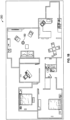
- FIG. 1b depicts a floorplan view of the first floor of the house according to some embodiments.
- the floorplan view is a top-down view of the first floor of the house.
- the user may interact with areas of the floorplan view, such as the area 150, to trigger an eye-level view of a particular portion of the floorplan, such as a living room.
- An example of the eye-level view of the living room can be found in FIG. 2 which may be part of a virtual walkthrough.
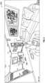
- FIG. 3 depicts one example of an environment capture system 300 according to some embodiments.
- the environment capture system 300 includes lens 310, a housing 320, a mount attachment 330, and a moveable cover 340.
- a user may command the environment capture system 300 to start a sweep.
- the sweep may be as follows:
- the housing 320 may protect the electronic components of the environment capture system 300 and may provide an interface for user interaction, with a power button, a scan button, and others.
- the housing 320 may include the moveable cover 340, which may be moveable to uncover the LiDAR.
- the housing 320 may include electronic interfaces, such as a power adapter and indicator lights.
- the housing 320 is a molded plastic housing.
- the housing 320 is a combination of one or more of plastic, metal, and polymer.
- a panoramic image of the physical environment is generated based on four images captured by the environment capture system 300 with a 25% overlap between images of the panoramic image. If there is no parallax, then 25% of one image may overlap exactly with another image of the same area of the physical environment. Eliminating or reducing the parallax effect of the multiple images captured by an image sensor through the lens 310 may aid in stitching multiple images into a 2D panoramic image.
- the lens 310 may include a large field of view (e.g., lens 310 may be a fisheye lens).
- the lens may have a horizontal FOV (HFOV) of at least 148 degrees and a vertical FOV (VFOV) of at least 94 degrees.
- HFOV horizontal FOV
- VFOV vertical FOV
- the mount attachment 330 may allow the environment capture system 300 to be attached to a mount.
- the mount may allow for the environment capture system 300 to be coupled with a tripod, flat surface, or motorized mount (e.g., to move the environment capture system 300).
- the mount may allow the environment capture system 300 to rotate along a horizontal axis.
- the environment capture system 300 may include a motor for turning the environment capture system 300 horizontally about the mount attachment 330.
- a motorized mount may move the environment capture system 300 along a horizontal axis, vertical axis, or both. In some embodiments, the motorized mount may rotate or move in the x-y plane.
- the use of a mount attachment 330 may allow for the environment capture system 300 to be coupled to a motorized mount, tripod, or the like to stabilize the environment capture system 300 to reduce or minimize shaking.
- the mount attachment 330 may be coupled to a motorized mount that allows the 3D, and environment capture system 300 to rotate at a steady, known speed, which aids the LiDAR in determine the (x, y, z) coordinates of each laser pulse of the LiDAR.
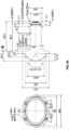
- FIG. 4 depicts a rendering of a environment capture system 400 in some embodiments.
- the rendering shows the environment capture system 400 (which may be an example of the environment capture system 300 of FIG. 3 ) from a variety of views, such as a front view 410, a top view 420, a side view 430, and a back view 440.
- the environment capture system 400 may include an optional hollow portion depicted in the side view 430.
- the housing of the 3D and 4environment capture system 400 may protect the electronic components of the environment capture system 400 and may provide an interface (e.g., screen on back view 440) for user interaction. Furthermore, the housing may include electronic interfaces, such as a power adapter and indicator lights. In some embodiments, the housing is a molded plastic housing. In various embodiments, the housing is a combination of one or more of plastic, metal, and polymer.
- the environment capture system 400 may include a moveable cover, which may be moveable to uncover the LiDAR and protect the LiDAR from the elements when not in use.
- the mount attachment at the base of the environment capture system 400 may allow the environment capture system to be attached to a mount.
- the mount may allow for the environment capture system 400 to be coupled with a tripod, flat surface, or motorized mount (e.g., to move the environment capture system 400). in some embodiments, the mount may be coupled to an internal motor for turning the environment capture system 400 about the mount.
- the mount may allow the environment capture system 400 to rotate along a horizontal axis.
- a motorized mount may move the environment capture system 400 along a horizontal axis, vertical axis, or both.
- the use of a mount attachment may allow for the environment capture system 400 to be coupled to a motorized mount, tripod, or the like to stabilize the environment capture system 400 to reduce or minimize shaking.
- the mount attachment may be coupled to a motorized mount that allows the environment capture system 400 to rotate at a steady, known speed, which aids the LiDAR in determining the (x, y, z) coordinates of each laser pulse of the LiDAR.
- a LiDAR may emit a laser pulse to the mirror (in a direction that is opposite the lens view).
- the laser pulse may hit the mirror 450 which may be angled (e.g., at a 90 degree angle)
- the mirror 450 may be coupled to an internal motor that turns the mirror such at the laser pulses of the LiDAR may be emitted and/or received at many different angles around the environment capture system 400.
- FIG. 5 is a depiction of the laser pulses from the LiDAR about the environment capture system 400 in some embodiments.
- the laser pulses are emitted at the spinning mirror 450.
- the laser pulses may be emitted and received perpendicular to a horizontal axis 602 (see FIG. 6 ) of the environment capture system 400.
- the mirror 450 may be angled such that laser pulses from the LiDAR are directed away from the environment capture system 400.
- the angle of the angled surface of the mirror may be 90 degrees or be at or between 60 degree to 120 degrees.
- the depth data may be associated with coordinates about the environment capture system 400.
- pixels or parts of images may be associated with the coordinates about the environment capture system 400 to enable the creation of the 3D visualization (e.g., an image from different directions, a 3D walkthrough, or the like) to be generated using the images and the depth data.
- the LiDAR pulses may be blocked by the bottom portion of the environment capture system 400.
- the mirror 450 may spin consistently while the environment capture system 400 moves about the mount or the mirror 450 may spin more slowly when the environment capture system 400 starts to move and again when the environment capture system 400 slows to stop (e.g., maintaining a constant speed between the starting and stopping of the mount motor).
- the LiDAR may receive depth data from the pulses. Due to movement of the environment capture system 400 and/or the increase or decrease of the speed of the mirror 450, the density of depth data about the environment capture system 400 may be inconsistent (e.g., more dense in some areas and less dense in others).
- the LiDAR pulses are discussed as being perpendicular to the horizontal axis 602, it will be appreciated that the LiDAR pulses may be at any angle relative to the horizontal axis 602 (e.g., the mirror angle may be at any angle including between 60 to 120 degrees).
- the LiDAR emits pulses opposite a front side (e.g., front side 604) of the environment capture system 400 (e.g., in a direction opposite of the center of the field of view of the lens or towards the back side 606).
- the images from a single sweep (e.g., the four sets of images) of the environment capture system 400 is sufficient along with the depth data acquired during the same sweep to generate the 3D visualization without any additional sweeps or turns of the environment capture system 400.
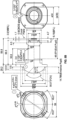
- LiDAR pulses are emitted and directed by the spinning mirror in a position that is distant from the point of rotation of the environment capture system 400.
- the distance from the point of rotation of the mount is 608 (e.g., the lens may be at the no-parallax point while the lens may be in a position behind the lens relative to the front of the environment capture system 400).
- the LiDAR pulses are directed by the mirror 450 at a position that is off the point of rotation, the LiDAR may not receive depth data from a cylinder running from above the environment capture system 400 to below the environment capture system 400.
- the radius of the cylinder e.g., the cylinder being a lack of depth information
- cavity 610 is depicted.
- the environment capture system 400 includes the spinning mirror within the body of the housing of the environment capture system 400. There is a cut-out section from the housing. The laser pulses may be reflected by the mirror out of the housing and then reflections may be received by the mirror and directed back to the LiDAR to enable the LiDAR to create depth signals and/or depth data.
- the base of the body of the environment capture system 400 below the cavity 610 may block some of the laser pulses.
- the cavity 610 ma be defined by the base of the environment capture system 400 and the rotating mirror. As depicted in FIG. 6b , there may still be a space between an edge of the angled mirror and the housing of the environment capture system 400 containing the LiDAR.
- the LiDAR is configured to stop emitting laser pulses if the speed of rotation of the mirror drops below a rotating safety threshold (e.g., if there is a failure of the motor spinning the mirror or the mirror is held in place). In this way, the LiDAR may be configured for safety and reduce the possibility that a laser pulse will continue to be emitted in the same direction (e.g., at a user's eyes).
- a rotating safety threshold e.g., if there is a failure of the motor spinning the mirror or the mirror is held in place.
- FIG. 6b depicts a view from above the environment capture system 400 in some embodiments.
- the front of the environment capture system 400 is depicted with the lens recessed and above directly above the center of the point of rotation (e.g., above the center of the mount).
- the front of the camera is recessed for the lends and the front of the housing is flared to allow the field of view of the image sensor to be unobstructed by the housing.
- the mirror 450 is depicted as pointing upwards.
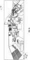
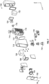
- FIG. 7 depicts a rendering of the components of one example of the environment capture system 300 according to some embodiments.
- the environment capture system 700 includes a front cover 702, a lens assembly 704, a structural frame 706, a LiDAR 708, a front housing 710, a mirror assembly 712, a GPS antenna 714, a rear housing 716, a vertical motor 718, a display 720 a battery pack 722, a mount 724, and a horizontal motor 726.
- the environment capture system 700 may be configured to scan, align, and create 3D mesh outdoors in full sun as well as indoors. This removes a barrier to the adoption of other systems which are an indoor-only tool.
- the environment capture system 700 may be able to scan large spaces more quickly than other devices.
- the environment capture system 700 may, in some embodiments, provide an improved depth accuracy by improving single scan depth accuracy at 90m.
- the environment capture system 700 may weigh 1 kg or about 1 kg. In one example, the environment capture system 700 may weigh between 1-3 kg.
- the front cover 702, the front housing 710, and the rear housing 716 make up a part of the housing.
- the front cover may have a width, w, of 75 mm.
- the lens assembly 704 may include a camera lens that focuses light onto an image capture device.
- the image capture device may capture an image of a physical environment.
- the user may place the environment capture system 700 to capture one portion of a floor of a building, such as the second building 422 of FIG. 1 to obtain a panoramic image of the one portion of the floor.
- the environment capture system 700 may be moved to another portion of the floor of the building to obtain a panoramic image of another portion of the floor.
- the depth of field of the image capture device is 0.5 meters to infinity.
- FIG. 8a depicts example lens dimensions in some embodiments.
- the image capture device is a complementary metal-oxide-semiconductor (CMOS) image sensor (e.g., a Sony IMX283 ⁇ 20 Megapixel CMOS MIPI sensor with the NVidia Jetson Nano SOM).
- CMOS complementary metal-oxide-semiconductor
- the image capture device is a charged coupled device (CCD).
- the image capture device is a red-green-blue (RGB) sensor.
- the image capture device is an infrared (IR) sensor.
- the lens assembly 704 may be give the image capture device a wide field of view.
- the image sensor may have many different specifications.
- the image sensor includes the following: Pixels per Column pixels 5496 Pixels per Row pixels 3694 Resolution MP > 20 Image circle diameter mm 15.86 mm Pixel pitch um 2.4 um Pixels Per Degree (PPD) PPD > 37 Chief ray angle at full height degree s 3.0° Output Interface - MIPI Green Sensitivity V/lux*s > 1.7 SNR (100 lux, 1x gain) dB > 65 Dynamic Range dB > 70
- the focus shift in looking at the MTF at F0 relative field (ie., the center), the focus shift may vary from +28 microns at 0.5m to -25 microns at infinity for a total through focus shift of 53 microns.
- FIG. 8b depicts example lens design specifications in some embodiments.
- the lens assembly 704 has an HFOV of at least 148 degrees and a VFOV of at least 94 degrees. In one example, the lens assembly 704 has a field of view of 150°, 180°, or be within a range of 145° to 180°. Image capture of a 360° view around the environment capture system 700 may be obtained, in one example, with three or four separate image captures from the image capture device of environment capture system 700. In various embodiments, the image capture device may have a resolution of at least 37 pixels per degree. In some embodiments, the environment capture system 700 includes a lens cap (not shown) to protect the lens assembly 704 when it is not in use. The output of the lens assembly 704 may be a digital image of one area of the physical environment.
- the images captured by the lens assembly 704 may be stitched together to form a 2D panoramic image of the physical environment.
- a 3D panoramic may be generated by combining the depth data captured by the LiDAR 708 with the 2D panoramic image generated by stitching together multiple images from the lens assembly 704.
- the images captured by the environment capture system 402 are stitched together by the image processing system 406.
- the environment capture system 402 generates a "preview" or "thumbnail” version of a 2D panoramic image.
- the preview or thumbnail version of the 2D panoramic image may be presented on a user system 1110 such as an iPad, personal computer, smartphone, or the like.
- the environment capture system 402 may generate a mini-map of a physical environment representing an area of the physical environment.
- the image processing system 406 generates the mini-map representing the area of the physical environment.
- the images captured by the lens assembly 704 may include capture device location data that identifies or indicates a capture location of a 2D image.
- the capture device location data can include a global positioning system (GPS) coordinates associated with a 2D image.
- GPS global positioning system
- the capture device location data can include position information indicating a relative position of the capture device (e.g., the camera and/or a 3D sensor) to its environment, such as a relative or calibrated position of the capture device to an object in the environment, another camera in the environment, another device in the environment, or the like.
- this type of location data can be determined by the capture device (e.g., the camera and/or a device operatively coupled to the camera comprising positioning hardware and/or software) in association with the capture of an image and received with the image.
- the capture device e.g., the camera and/or a device operatively coupled to the camera comprising positioning hardware and/or software
- the placement of the lens assembly 704 is not solely by design. By placing the lens assembly 704 at the center, or substantially at the center, of the axis of rotation, the parallax effect may be reduced.
- the structural frame 706 holds the lens assembly 704 and the LiDAR 708 in a particular position and may help protect the components of the example of the environment capture system.
- the structural frame 706 may serve to aid in rigidly mounting the LiDAR 708 and place the LiDAR 708 in a fixed position.
- the fixed position of the lens assembly 704 and the LiDAR 708 enable a fixed relationship to align the depth data with the image information to assist with creating the 3D images.
- the 2D image data and depth data captured in the physical environment can be aligned relative to a common 3D coordinate space to generate a 3D model of the physical environment.
- the LiDAR 708 may return depth data points every 10useconds with a timestamp (of an internal clock).
- the LiDAR 708 may sample a partial sphere (small holes at top and bottom) every 0.25 degrees.
- the LiDAR 708 specification may be as follows: Range (10% reflectance) m 90 Range (20% reflectance) m 130 Range (100% reflectance) m 260 Range Precision (1 ⁇ @ 20 m) cm 2 Wavelength nm 905 Laser Safety -- Class 1 Point Rate points/ s 100,000 Beam Divergence degree s 0.28 ⁇ 0.03 Angular Resolution deg 0.1 Collimated Beam Dimensions (@ 10cm) mm 14.71 ⁇ 8.46 Operating Temperature deg C -20 to 65 Power (normal mode, active) W 4.83 Power (normal mode, idle) W 4.38 Power (standby mode) W 4.07 Time to Active from Off s 3.898 Time to Active from Standby s 0.289 Time to Active from Normal Idle s 0.003 Voltage V 10-15.6 Data synchronization -- Pulse Per Second (PPS) Dimensions mm 60 ⁇ 58 ⁇ 56 Weight g 230 Data Latency ms 2 False Alarm Rate (@ 100 klx) % ⁇ 0.01%
- LiDAR a LiDAR at the lower wavelength (e.g., 905 nm, 900-940 nm, or the like) it may allow the environment capture system 700 to determine depth information for an outdoor environment or an indoor environment with bright light.
- the placement of the lens assembly 704 and the LiDAR 708 may allow the environment capture system 700 or a digital device in communication with the environment capture system 700 to generate a 3D panoramic image using the depth data from the LiDAR 708 and the lens assembly 704.
- the 2D and 3D panoramic images are not generated on the environment capture system 402.
- the output of the LiDAR 708 may include attributes associated with each laser pulse sent by the LiDAR 708.
- the attributes include the intensity of the laser pulse, number of returns, the current return number, classification point, RGC values, GPS time, scan angle, the scan direction, or any combination therein.
- the depth of field may be (0.5 m; infinity), (1 m; infinity), or the like. In some embodiments, the depth of field is 0.2 m to 1 m and infinity.
- the environment capture system 700 captures four separate RBG images using the lens assembly 704 while the environment capture system 700 is stationary.
- the LiDAR 708 captures depth data in four different instances while the environment capture system 700 is in motion, moving from one RBG image capture position to another RBG image capture position.
- the 3D panoramic image is captured with a 360° rotation of the environment capture system 700, which may be called a sweep. In various embodiments, the 3D panoramic image is captured with a less than 360° rotation of the environment capture system 700.
- the output of the sweep may be a sweep list (SWL), which includes image data from the lens assembly 704 and depth data from the LiDAR 708 and properties of the sweep, including the GPS location and a timestamp of when the sweep took place.
- SWL sweep list
- a single sweep e.g., a single 360 degree turn of the environment capture system 700 captures sufficient image and depth information to generate a 3D visualization (e.g., by the digital device in communication with the environment capture system 700 that receives the imagery and depth data from the environment capture system 700 and creates the 3D visualization using only the imagery and depth data from the environment capture system 700 captured in the single sweep).
- the images captured by the environment capture system 402 may be blended, stitched together, and combined with the depth data from the LiDAR 708 by an image stitching and processing system discussed herein.
- the environment capture system 402 may generate a top-down view of the physical environment. A user may use this information to determine areas of the physical environment in which the user has not captured or generated 3D panoramic images.
- the environment capture system 700 may interleave image capture with the image capture device of the lens assembly 704 with depth information capture with the LiDAR 708.
- the image capture device may capture an image of section 1605, as seen in FIG. 16 , of the physical environment with the image capture device, and then LiDAR 708 obtains depth information from section 1605.
- the image capture device may move on to capture an image of another section 1610, and then LiDAR 708 obtains depth information from section 1610, thereby interleaving image capture and depth information capture.
- the LiDAR 708 may have a field of view of at least 145°, depth information of all objects in a 360° view of the environment capture system 700 may be obtained by the environment capture system 700 in three or four scans. In another example, the LiDAR 708 may have a field of view of at least 150°, 180°, or between 145 ° to 180 °.
- the LiDAR 708 has a minimum depth range of 0.5m. In one embodiment, the LiDAR 708 has a maximum depth range of greater than 8 meters.
- the LiDAR 708 may utilize the mirror assembly 712 to direct the laser in different scan angles.
- the optional vertical motor 718 has the capability to move the mirror assembly 712 vertically.
- the mirror assembly 712 may be a dielectric mirror with a hydrophobic coating or layer.
- the mirror assembly 712 may be coupled to the vertical motor 718 that rotates the mirror assembly 712 when in use.
- the mirror of the mirror assembly 712 may, for example, include the following specification for materials and coatings: S1L1 material Dielectric S1L2 material Hydrophobic S2L1 material Black Paint Emulsion Powdersuspendedinpaint Substrate material Schott B270I
- the hydrophobic coating of the mirror of the mirror assembly 712 may, for example, include a Contact Angle deg >105.
- the mirror of the mirror assembly 712 may include the following quality specifications: Scratch/Dig Standard 3 HTS: 80C, 50hrs. 3 LTS: -30C, 1000hrs. 3 THS: 60C/90%RH, 1000hrs. 3 TC: -30 to 70C, 50 eye (30min./5min./30min.) 3 (Solvent Resistance), Side a, 50 wipes with ethanol, alcohol, 300g (Solvent Resistance), Side b, 10 wipes with ethanol, alcohol, 200g 3 (Abrasion Resistance), Side a, 50 wipes, 300g (Abrasion Resistance), Side b, 10 wipes, 200g 3 (Durability), Side a, 10 tape peels (CT-18) (Durability), Side b, 5 tape peels (CT-18) 3 UV Resistance (Outdoor environment 3 simulation, 340nm, 0.35 W/m ⁇ 2/nm irradiance, 306 min light at 125C BTP 54 min. light and deionized water spray (uncontrolled temp) 6h dark at 9
- the vertical motor may include, for example, the following specifications: Maximum Speed RPM 4000 and 6500 Maximum Acceleration deg/sec ⁇ 2 300 Durability Cycle 70000 Motor Driver Accuracy 1 revolution time variance standard deviation of ⁇ 5 ⁇ sec
- the environment capture system 700 may capture images outside in bright sunlight or inside with bright lights or sunlight glare from windows.
- devices e.g., structured light devices
- they may not be able to operate in bright environments, whether inside or outside. Those devices are often limited to use only inside and only during dawn or sunset to control light. Otherwise, bright spots in a room create artifacts or "holes" in images that must be filled or corrected.
- the environment capture system 700 may be utilized in bright sunlight both inside and outside.
- the capture device and the LiDAR 708 may be able to capture image and depth data in bright environments without artifacts or holes caused by glare or bright light.
- the GPS antenna 714 receives global positioning system (GPS) data.
- GPS global positioning system
- the GPS data may be used to determine the location of the environment capture system 700 at any given time.
- the battery pack 722 provides power to the environment capture system 700.
- the battery pack 722 may be removable and rechargeable, thereby allowing a user to put in a fresh battery pack 722 while charging a depleted battery pack.
- the battery pack 722 may allow at least 1000 SWLs or at least 250 SWLs of continuous use before recharging.
- the environment capture system 700 may utilize a USB-C plug for recharging.
- the mount 724 provides a connector for the environment capture system 700 to connect to a platform such as a tripod or mount.
- the horizontal motor 726 may rotate the environment capture system 700 around an x-y plane.
- the horizontal motor 726 may provide information to a grid coordinate system to determine (x, y, z) coordinates associated with each laser pulse.
- the horizontal motor 726 may enable the environment capture system 700 to scan quickly.
- the mount 724 may include a quick release adapter.
- the holding torque may be, for example, >2.0 Nm and the durability of the capture operation may be up to or beyond 70,000 cycles.
- these components provide the environment capture system 700 the ability to align scan positions outdoor as well as indoor and therefore create seamless walk-through experiences between indoor and outdoor (this may be a high priority for hotels, vacation rentals, real estate, construction documentation, CRE, and as-built modeling and verification.
- the environment capture system 700 may also create an "outdoor dollhouse" or outdoor mini-map.
- the environment capture system 700 may also improve the accuracy of the 3D reconstruction, mainly from a measurement perspective. For scan density, the ability for the user to tune it may also be a plus.
- These components may also enable the environment capture system 700 the ability to capture wide empty spaces (e.g., longer range). In order to generate a 3D model of wide empty spaces may require the environment capture system to scan and capture 3D data and depth data from a greater distance range than generating a 3D model of smaller spaces.
- these components enable the environment capture system 700 to align SWLs and reconstruct the 3D model in a similar way for indoor as well as outdoor use. These components may also enable the environment capture system 700 to perform geo-localization of 3D models (which may ease integration to Google street view and help align outdoor panoramas if needed).
- the image capture device of the environment capture system 700 may be able to provide a DSLR-like Image with quality printable at 8.5" ⁇ 11" for 70° VFOV and an RGB image style.
- the environment capture system 700 may take an RGB image with the image capture device (e.g., using the wide-angle lens) and then move the lens before taking the next RGB image (for a total of four movements using the motor). While the horizontal motor 726 rotates the environment capture system 90 degrees, the LiDAR 708 may capture depth data. In some embodiments, the LiDAR 708 includes an APD array.
- the image and depth data may then be sent to a capture application (e.g., a device in communication with the environment capture system 700, such as a smart device or an image capture system on a network).
- the environment capture system 700 may send the image and depth data to the image processing system 406 for processing and generating the 2D panoramic image or the 3D panoramic image.
- the environment capture system 700 may generate a sweep list of the captured RGB image and the depth data from a 360-degree revolution of the environment capture system 700.
- the sweep list may be sent to the image processing system 406 for stitching and aligning.
- the output of the sweep may be a SWL, which includes image data from the lens assembly 704 and depth data from the LiDAR 708 and properties of the sweep, including the GPS location and a timestamp of when the sweep took place.
- the LIDAR, vertical mirror, RGB lens, tripod mount, and horizontal drive are rigidly mounted within the housing to allow the housing to be opened without requiring the system to be recalibrated.
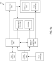
- FIG. 9a depicts a block diagram 900 of an example of an environment capture system according to some embodiments.
- the block diagram 900 includes a power source 902, a power converter 904, an input/output (I/O) printed circuit board assembly (PCBA), a system on module (SOM) PCBA, a user interface 910, a LiDAR 912, a mirror brushless direct current (BLCD) motor 914, a drive train 916, wide FOV (WFOV) lens 918, and an image sensor 920.
- I/O input/output
- PCBA input/output printed circuit board assembly
- SOM system on module
- the power source 902 may be the battery pack 722 of FIG. 7 .
- the power source may be a removable, rechargeable battery, such as a lithium-ion battery (e.g., 4x 18650 Li-Ion cell) capable of providing power to the environment capture system.
- a lithium-ion battery e.g., 4x 18650 Li-Ion cell
- the power converter 904 may change the voltage level from the power source 902 to a lower or higher voltage level so that it may be utilized by the electronic components of the environment capture system.
- the environment capture system may utilize 4x 18650 Li-Ion cells in 4S1P configuration, or four series connections and one parallel connection configuration.
- the I/O PCBA 906 may include elements that provide IMU, Wi-Fi, GPS, Bluetooth, inertial measurement unit (IMU), motor drivers, and microcontrollers.
- the I/O PCBA 906 includes a microcontroller for controlling the horizontal motor and encoding horizontal motor controls as well as controlling the vertical motor and encoding vertical motor controls.
- the SOM PCBA 908 may include a central processing unit (CPU) and/or graphics processing unit (GPU), memory, and mobile interface.
- the SOM PCBA 908 may control the LiDAR 912, the image sensor 920, and the I/O PCBA 906.
- the SOM PCBA 908 may determine the (x, y, z) coordinates associated with each laser pulse of the LiDAR 912 and store the coordinates in a memory component of the SOM PCBA 908. In some embodiments, the SOM PCBA 908 may store the coordinates in the image processing system of the environment capture system 400.
- the SOM PCBA 908 may determine additional attributes associated with each laser pulse, including the intensity of the laser pulse, number of returns, the current return number, classification point, RGC values, GPS time, scan angle, and the scan direction.
- the SOM PCBA 908 include an Nvidia SOM PCBA w/ CPU/GPU, DDR, eMMC, Ethernet.
- the user interface 910 may include physical buttons or switches with which the user may interact with.
- the buttons or switches may provide functions such as turn the environment capture system on and off, scan a physical environment, and others.
- the user interface 910 may include a display such as the display 720 of FIG. 7 .
- the LiDAR 912 captures depth information of the physical environment.
- the LiDAR 912 includes an optical sensing module that can measure the distance to a target or objects in a scene by irradiating the target or scene with light, using pulses from a laser.
- the optical sensing module of the LiDAR 912 measures the time it takes photons to travel to said target or object and return after reflection to a receiver in the LiDAR 912, thereby giving a distance of the LiDAR from the target or object.
- the SOM PCBA 908 may determine the (x, y, z) coordinates associated with each laser pulse.
- the LiDAR 912 may fit within a width of 58 mm, a height of 55 mm, and a depth of 60 mm.
- the LiDAR 912 may include a range (10% reflectance) of 90 m, range (20% reflectance) 130 m, range (100% reflectance) 260 m, a range precision (1 ⁇ @ 900 m) of 2 cm, a wavelength 1705 nm, and beam divergence of 0.28 ⁇ 0.03 degrees.
- the SOM PCBA 908 may determine the coordinates based on the location of the drive train 916.
- the LiDAR 912 may include one or more LiDAR devices. Multiple LiDAR devices may be utilized to increase the LiDAR resolution.
- the mirror brushless direct current (BLCD) motor 914 may control the mirror assembly 712 of FIG. 7 .
- the drive train 916 may include the horizontal motor 726 of FIG. 7 .
- the drive train 916 may provide rotation of the environment capture system when it is mounted on a platform such as a tripod.
- the drive train 916 may include a stepper motor Nema 14, worm & plastic wheel drive train, clutch, bushing bearing, and a backlash prevention mechanism.
- the environment capture system may be able to complete a scan in less than 17 seconds.
- the drive train 916 has a maximum speed of 60 degrees /second, a maximum acceleration of 300 degrees /seconds 2 , a maximum torque of 0.5 nm, an angular position accuracy of less than 0.1 degrees, and an encoder resolution of about 4096 counts per revolution.
- the WFOV lens 918 may be the lens of the lens assembly 704 of FIG. 7 .
- the WFOV lens 918 focuses light onto an image capture device.
- the WFOV lens may have a FOV of at least 145 degrees. With such a wide FOV, an image capture of a 360-degree view around the environment capture system may be obtained with three separate image captures of the image capture device.
- the WFOV lens 918 may be about ⁇ 60mm diameter and ⁇ 80mm total track length (TTL).
- the WFOV lens 918 may include a horizontal field of view that is greater than or equal to 148.3 degrees and a vertical field of view that is greater than or equal to 94 degrees.
- An image capture device may include the WFOV lens 918 and the image sensor 920.
- the image sensor 920 may be a CMOS image sensor.
- the image sensor 920 is a charged coupled device (CCD).
- the image sensor 920 is a red-green-blue (RGB) sensor.
- the image sensor 920 is an IR sensor.
- the image capture device may have a resolution of at least 35 pixels per degree (PPD).
- the lens may include F-number 2.8, Image circle diameter 15.86 mm, Pixels per degree > 37, Chief ray angle at sensor full height 3.0, L1 diameter ⁇ 60 mm, TTL ⁇ 80 mm, and Relative illumination > 50 %,.
- the lens may include 52 lp/mm (on-axis) > 85%, 104 lp/mm (on-axis) > 66%, 1308 lp/mm (on-axis) > 45%, 52 lp/mm (83% field) > 75%, 104 lp/mm (83% field) > 41%, and 1308 lp/mm (83% field) > 25 %.
- the environment capture system may have a resolution of >20 MP, green sensitivity >1.7 V/lux*s, SNR (100 lux, 1x gain) >65dB, and a dynamic range of >70 dB.
- the communication component 922 may send and receive requests or data between any of the components of the SOM PCBA 1008 and components of the environment capture system of FIG. 9a .
- the LiDAR control component 924 may control various aspects of the LiDAR. For example, the LiDAR control component 924 may send a control signal to the LiDAR 912 to start sending out a laser pulse. The control signal sent by the LiDAR control component 924 may include instructions on the frequency of the laser pulses.
- the LiDAR location component 926 may utilize GPS data to determine the location of the environment capture system. In various embodiments, the LiDAR location component 926 utilizes the position of the mirror assembly to determine the scan angle and (x, y, z) coordinates associated with each laser pulse. The LiDAR location component 926 may also utilize the IMU to determine the orientation of the environment capture system.
- the user interface component 928 may facilitate user interaction with the environment capture system.
- the user interface component 928 may provide one or more user interface elements with which a user may interact.
- the user interface provided by the user interface component 928 may be sent to the user system 1110.
- the user interface component 928 may provide to the user system (e.g., a digital device) a visual representation of an area of a floorplan of a building.
- the environment capture system may generate the visual representation of the floorplan.
- the user may place the environment capture system in an area of the physical environment to capture and generate 3D panoramic images in that region of the house.
- the user interface component may update the floorplan view with a top-down view of the living room area depicted in FIG. 1b .
- the floorplan view 200 may be generated by the user system 1110 after a second sweep of the same home, or floor of a building has been captured.
- the classification component 930 may classify the type of physical environment.
- the classification component 930 may analyze objects in the images or objects in images to classify the type of physical environment was captured by the environment capture system.
- the image processing system may be responsible for classifying the type of physical environment that was captured by the environment capture system 400.
- the LiDAR datastore 932 may be any structure and/or structures suitable for captured LiDAR data (e.g., an active database, a relational database, a self-referential database, a table, a matrix, an array, a flat file, a documented-oriented storage system, a non-relational No-SQL system, an FTS-management system such as Lucene/Solar, and/or the like).
- the image datastore 408 may store the captured LiDAR data.
- the LiDAR datastore 932 may be utilized to cache the captured LiDAR data in cases where the communication network 404 is non-functional.
- the LiDAR datastore 932 may store the captured LiDAR data until they can be transferred to the image datastore 934.
- the captured image datastore 934 may be any structure and/or structures suitable for captured images (e.g., an active database, a relational database, a self-referential database, a table, a matrix, an array, a flat file, a documented-oriented storage system, a non-relational No-SQL system, an FTS-management system such as Lucene/Solar, and/or the like).
- the image datastore 934 may store the captured images.
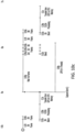
- FIG. 10a-10c depicts a process for the environment capture system 400 for taking images in some embodiments.
- the environment capture system 400 may take a burst of images at different exposures.
- a burst of images may be a set of images, each with different exposures.
- the first image burst happens at time 0.0.
- the environment capture system 400 may receive the first frame and then assess the frame while waiting for the second frame.
- FIG. 10a indicates that the first frame is blended before the second frame arrives.
- the environment capture system 400 may process each frame to identify pixels, color, and the like. Once the next frame arrives, the environment capture system 400 may process the recently received frame and then blend the two frames together.
- the environment capture system 400 performs image processing to blend the sixth frame and further assess the pixels in the blended frame (e.g., the frame that may include elements from any number of the frames of the image burst).
- the environment capture system 400 may optionally transfer the blended image from the graphic processing unit to CPU memory.
- FIG. 10b The process continues in FIG. 10b .
- the environment capture system 400 may compress the blended frames and/or all or parts of the captured frames using JxR).
- a burst of images may be a set of images, each with different exposures (the length of exposure for each frame the set may the same and in the same order as other bursts covered in FIG. 10a and 10c ).
- the second image burst happens at time 2 second.
- the environment capture system 400 may receive the first frame and then assess the frame while waiting for the second frame.
- FIG. 10b indicates that the first frame is blended before the second frame arrives.
- the environment capture system 400 may process each frame to identify pixels, color, and the like. Once the next frame arrives, the environment capture system 400 may process the recently received frame and then blend the two frames together.
- the environment capture system 400 performs image processing to blend the sixth frame and further assess the pixels in the blended frame (e.g., the frame that may include elements from any number of the frames of the image burst).
- the environment capture system 400 may optionally transfer the blended image from the graphic processing unit to CPU memory.
- the environment capture system 400 may continue the process by conducting another color burst (e.g., after turning 180 degrees) at about time 3.5 seconds.
- the environment capture system 400 may compress the blended frames and/or all or parts of the captured frames using JxR).
- the burst of images may be a set of images, each with different exposures (the length of exposure for each frame the set may the same and in the same order as other bursts covered in FIG. 10a and 10c ).
- the environment capture system 400 may receive the first frame and then assess the frame while waiting for the second frame.
- FIG. 10b indicates that the first frame is blended before the second frame arrives.
- the environment capture system 400 may process each frame to identify pixels, color, and the like. Once the next frame arrives, the environment capture system 400 may process the recently received frame and then blend the two frames together.
- the environment capture system 400 performs image processing to blend the sixth frame and further assess the pixels in the blended frame (e.g., the frame that may include elements from any number of the frames of the image burst).
- the environment capture system 400 may optionally transfer the blended image from the graphic processing unit to CPU memory.
- the dynamic range of an image capture device is a measure of how much light an image sensor can capture.
- the dynamic range is the difference between the darkest area to the brightest area of an image.
- There are many ways to increase the dynamic range of the image capture device one of which is to capture multiple images of the same physical environment using different exposures. An image captured with a short exposure will capture brighter areas of the physical environment, while a long exposure will capture darker physical environment areas.
- the environment capture system may capture multiple images with six different exposure times. Some or all of the images captured by the environment capture system are used to generate 2D images with high dynamic range (HDR).
- HDR high dynamic range
- One or more of the captured images may be used for other functions such as ambient light detection, flicker detection, and the like.
- a 3D panoramic image of the physical environment may be generated based on four separate image captures of the image capture device and four separate depth data capture of the LiDAR device of the environment capture system. Each of the four separate image captures may include a series of image captures of different exposure times.
- a blending algorithm may be used to blend the series of image captures with the different exposure times to generate one of four RGB image captures, which may be utilized to generate a 2D panoramic image.
- the environment capture system may be used to capture a 3D panoramic image of a kitchen. Images of one wall of the kitchen may include a window, an image with an image captured with a shorter exposure may provide the view out the window but may leave the rest of the kitchen underexposed. In contrast, another image captured with a longer exposure may provide the view of the interior of the kitchen.
- the blending algorithm may generate a blended RGB image by blending the view out the window of the kitchen from one image with the rest of the kitchen's view from another image.
- the 3D panoramic image may be generated based on three separate image captures of the image capture device and four separate depth data captures of the LiDAR device of the environment capture system.
- the number of image captures, and the number of depth data captures may be the same. In one embodiment, the number of image captures, and the number of depth data captures may be different.
- a blending algorithm receives the first of the series of images, calculate initial intensity weights for that image, and set that image as a baseline image for combining the subsequently received images.
- the blending algorithm may utilize a graphic processing unit (GPU) image processing routine such as a "blend_kernel" routine.
- the blending algorithm may receive subsequent images that may be blended with previously received images.
- the blending algorithm may utilize a variation of the blend_kernel GPU image processing routine.
- the blending algorithm utilizes other methods of blending multiple images, such as determining the difference between the darkest and brightest part, or contrast, of the baseline image to determine if the baseline image may be overexposed or under-exposed. For example, a contrast value less than a predetermine contrast threshold means that the baseline image is overexposed or under-exposed.
- the contrast of the baseline image may be calculated by taking an average of the image's light intensity or a subset of the image.
- the blending algorithm calculates an average light intensity for each row or column of the image.
- the blending algorithm may determine a histogram of each of the images received from the image capture device and analyze the histogram to determine light intensities of the pixels which make up each of the images.
- the blending may involve sampling colors within two or more images of the same scene, including along objects and seems. If there is a significant difference in color between the two images (e.g., within a predetermined threshold of color, hue, brightness, saturation, and/or the like), a blending module (e.g., on the environment capture system 400 or the user device 1110) may blend a predetermined size of both images along the position where there is the difference. In some embodiments, the greater the difference in color or image at a position in the image, the greater the amount of space around or near the position may be blended.
- a blending module e.g., on the environment capture system 400 or the user device 1110 may blend a predetermined size of both images along the position where there is the difference. In some embodiments, the greater the difference in color or image at a position in the image, the greater the amount of space around or near the position may be blended.
- the blending module may re-scan and sample colors along the image(s) to determine if there are other differences in image or color that exceed the predetermined threshold of color, hue, brightness, saturation, and/or the like. If so, the blending module may identify the portions within the image(s) and continue to blend that portion of the image. The blending module may continue to resample the images along the seam until there are no further portions of the images to blend (e.g., any differences in color are below the predetermined threshold(s).)
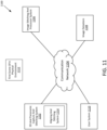
- FIG. 11 depicts a block diagram of an example environment 1100 capable of capturing and stitching images to form 3D visualizations according to some embodiments.
- the example environment 1100 includes 3D and panoramic capture and stitching system 1102, a communication network 1104, an image stitching and processor system 1106, an image datastore 1108, a user system 1110, and a first scene of a physical environment 1112.
- the 3D and panoramic capture and stitching system 1102 and/or the user system 1110 may include an image capture device (e.g., environment capture system 400) that may be used to capture images of an environment (e.g., the physical environment 1112).
- an image capture device e.g., environment capture system 400
- the 3D and panoramic capture and stitching system 1102 and the image stitching and processor system 1106 may be a part of the same system (e.g., part of one or more digital devices) that are communicatively coupled to the environment capture system 400. In some embodiments, one or more of the functionality of the components of the 3D and panoramic capture and stitching system 1102 and the image stitching and processor system 1106 may be performed by the environment capture system 400. Similarly or alternatively, 3D and panoramic capture and stitching system 1102 and the image stitching and processor system 1106 may be performed by the user system 1110 and/or the image stitching and processor system 1106
- the 3D panoramic capture and stitching system 1102 may be utilized by a user to capture multiple 2D images of an environment, such as the inside of a building and/or and outside of the building.
- the user may utilize the 3D and panoramic capture and stitching system 1102 to capture multiple 2D images of the first scene of the physical environment 1112 provided by the environment capture system 400.
- the 3D and panoramic capture and stitching system 1102 may include an aligning and stitching system 1114.
- the user system 1110 may include the aligning and stitching system 1114.
- the aligning and stitching system 1114 may be software, hardware, or a combination of both configured to provide guidance to the user of an image capture system (e.g., on the 3D and panoramic capture and stitching system 1102 or the user system 1110) and/or process images to enable improved panoramic pictures to be made (e.g., through stitching, aligning, cropping, and/or the like).
- the aligning and stitching system 1114 may be on a computer-readable media (described herein).
- the aligning and stitching system 1114 may include a processor for performing functions.
- An example of the first scene of the physical environment 1112 may be any room, real estate, or the like (e.g., a representation of a living room).
- the 3D and panoramic capture and stitching system 1102 is utilized to generate 3D panoramic images of indoor environments.
- the 3D panoramic capture and stitching system 1102 may, in some embodiments, be the environment capture system 400 discussed with regard to FIG. 4 .
- the 3D panoramic capture and stitching system 1102 may in communication with a device for capturing images and depth data as well as software (e.g., the environment capture system 400). All or part of the software may be installed on the 3D panoramic capture and stitching system 1102, the user system 1110, the environment capture system 400, or both. In some embodiments, the user may interact with the 3D and panoramic capture and stitching system 1102 via the user system 1110.
- the guidance may allow the user to capture multiple images of the physical environment without the help of a stabilizing platform such as a tripod.
- the image capture device may be a personal device such as a smartphone, tablet, media tablet, laptop, and the like.
- the application may provide direction on position for each sweep, to approximate the no-parallax point based on position of the image capture device, location information from the image capture device, and/or previous image of the image capture device.
- the visual and/or auditory guidance enables the capture of images that can be stitched together to form panoramas without a tripod and without camera positioning information (e.g., indicating a location, position, and/or orientation of the camera from a sensor, GPS device, or the like).
- camera positioning information e.g., indicating a location, position, and/or orientation of the camera from a sensor, GPS device, or the like.
- the aligning and stitching system 1114 may align or stitch 2D images (e.g., captured by the user system 1110 or the 3D panoramic capture and stitching system 1102) to obtain a 2D panoramic image.
- the aligning and stitching system 1114 utilizes a machine learning algorithm to align or stitch multiple 2D images into a 2D panoramic image.
- the parameters of the machine learning algorithm may be managed by the aligning and stitching system 1114.
- the 3D and panoramic capture and stitching system 1102 and/or the aligning and stitching system 1114 may recognize objects within the 2D images to aid in aligning the images into a 2D panoramic image.
- the aligning and stitching system 1114 may utilize depth data and the 2D panoramic image to obtain a 3D panoramic image.
- the 3D panoramic image may be provided to the 3D and panoramic stitching system 1102 or the user system 1110.
- the aligning and stitching system 1114 determines 3D/depth measurements associated with recognized objects within a 3D panoramic image and/or sends one or more 2D images, depth data, 2D panoramic image(s), 3D panoramic image(s) to the image stitching and processor system 106 to obtain a 2D panoramic image or a 3D panoramic image with pixel resolution that is greater than the 2D panoramic image or the 3D panoramic image provided by the 3D and panoramic capture and stitching system 1102.
- the communication network 1104 may represent one or more computer networks (e.g., LAN, WAN, or the like) or other transmission mediums.
- the communication network 1104 may provide communication between systems 1102, 1106-1110, and/or other systems described herein.
- the communication network 104 includes one or more digital devices, routers, cables, buses, and/or other network topologies (e.g., mesh, and the like).
- the communication network 1104 may be wired and/or wireless.
- the communication network 1104 may include the Internet, one or more wide area networks (WANs) or local area networks (LANs), one or more networks that may be public, private, IP-based, non-IP based, and so forth.
- the image stitching and processor system 1106 may process 2D images captured by the image capture device (e.g., the environment capture system 400 or a user device such as a smartphone, personal computer, media tablet, or the like) and stitch them into a 2D panoramic image.
- the 2D panoramic image processed by the image stitching and processor system 106 may have a higher pixel resolution than the panoramic image obtained by the 3D and panoramic capture and stitching system 1102.
- the image stitching and processor system 1106 receives and processes the 3D panoramic image to create a 3D panoramic image with pixel resolution that is higher than that of the received 3D panoramic image.
- the higher pixel resolution panoramic images may be provided to an output device with a higher screen resolution than the user system 1110, such as a computer screen, projector screen, and the like.
- the higher pixel resolution panoramic images may provide to the output device a panoramic image in greater detail and may be magnified.
- the image datastore 1108 may be any structure and/or structures suitable for captured images and/or depth data (e.g., an active database, a relational database, a self-referential database, a table, a matrix, an array, a flat file, a documented-oriented storage system, a non-relational No-SQL system, an FTS-management system such as Lucene/Solar, and/or the like).
- the image datastore 1108 may store images captured by the image capture device of the user system 1110.
- the image datastore 1108 stores depth data captured by one or more depth sensors of the user system 1110.
- the user system 1110 may communicate between users and other associated systems.
- the user system 1110 may be or include one or more mobile devices (e.g., smartphones, cell phones, smartwatches, or the like).
- the user system 1110 may include one or more image capture devices.
- the one or more image capture devices can include, for example, RGB cameras, HDR cameras, video cameras, IR cameras, and the like.
- the 3D and panoramic capture and stitching system 1102 and/or the user system 1110 may include two or more capture devices may be arranged in relative positions to one another on or within the same mobile housing such that their collective fields of view span up to 360°.
- pairs of image capture devices can be used capable of generating stereo-image pairs (e.g., with slightly offset yet partially overlapping fields of view).
- the user system 1110 may include two image capture devices with vertical stereo offset fields-of-view capable of capturing vertical stereo image pairs.
- the user system 1110 can comprise two image capture devices with vertical stereo offset fields-of-view capable of capturing vertical stereo image pairs.
- the user system 1110, environment capture system 400, or the 3D and panoramic capture and stitching system 1102 may generate and/or provide image capture position and location information.
- the user system 1110 or the 3D and panoramic capture and stitching system 1102 may include an inertial measurement unit (IMU) to assist in determining position data in association with one or more image capture devices that capture the multiple 2D images.
- the user system 1110 may include a global positioning sensor (GPS) to provide GPS coordinate information in association with the multiple 2D images captured by one or more image capture devices.
- GPS global positioning sensor
- users may interact with the aligning and stitching system 1114 using a mobile application installed in the user system 1110.
- the 3D and panoramic capture and stitching system 1102 may provide images to the user system 1110.
- a user may utilize the aligning and stitching system 1114 on the user system 1110 to view images and previews.
- the aligning and stitching system 1114 may be configured to provide or receive one or more 3D panoramic images from the 3D and panoramic capture and stitching system 1102 and/or the image stitching and processor system 1106.
- the 3D and panoramic capture and stitching system 1102 may provide a visual representation of a portion of a floorplan of a building, which has been captured by the 3D and panoramic capture and stitching system 1102 to the user system 1110.
- the user of the system 1110 may navigate the space around the area and view different rooms of the house.
- the user of the user system 1110 may display the 3D panoramic images, such as the example 3D panoramic image, as the image stitching and processor system 1106 completes the generation of the 3D panoramic image.
- the user system 1110 generates a preview or thumbnail of the 3D panoramic image.
- the preview 3D panoramic image may have an image resolution that is lower than a 3D panoramic image generated by the 3D and panoramic capture and stitching system 1102.
- FIG. 12 is a block diagram of an example of the align and stitching system 1114 according to some embodiments.
- the align and stitching system 1114 includes a communication module 1202, an image capture position module 1204, a stitching module 1206, a cropping module 1208, a graphical cut module 1210, a blending module 1211, a 3D image generator 1214, a captured 2D image datastore 1216, a 3D panoramic image datastore 1218, and a guidance module 220. It may be appreciated that there may be any number of modules of the aligning and stitching system 1114 that perform one or more different functions as described herein.
- the aligning and stitching system 1114 includes an image capture module configured to receive images from one or more image capture devices (e.g., cameras).
- the aligning and stitching system 1114 may also include a depth module configured to receive depth data from a depth device such as a LiDAR if available.
- the image capture position module 1204 may determine image capture device position data of an image capture device (e.g., a camera which may be a stand-alone camera, smartphone, media tablet, laptop, or the like). Image capture device position data may indicate a position and orientation of an image capture device and/or lens. In one example, the image capture position module 1204 may utilize the IMU of the user system 1110, camera, digital device with a camera, or the 3D and panoramic capture and stitching system 1102 to generate position data of the image capture device. The image capture position module 1204 may determine the current direction, angle, or tilt of one or more image capture devices (or lenses). The image capture position module 1204 may also utilize the GPS of the user system 1110 or the 3D and panoramic capture and stitching system 1102.
- an image capture device e.g., a camera which may be a stand-alone camera, smartphone, media tablet, laptop, or the like.
- Image capture device position data may indicate a position and orientation of an image capture device and/or lens.
- the aligning and stitching system 1114 may receive position information (e.g., from the IMU) to determine the position of the image capture device or lens.
- the aligning and stitching system 1114 may receive and store a field of view of the lens.
- the guidance module 1220 may provide visual and/or audio information regarding a recommended initial position of the image capture device.
- the guidance module 1220 may make recommendations for positioning the image capture device for subsequent images.
- the guidance module 1220 may provide guidance to the user to rotate and position the image capture device such that the image capture device rotates close to a center of rotation. Further, the guidance module 1220 may provide guidance to the user to rotate and position the image capture device such that subsequent images are substantially aligned based on characteristics of the field of view and/or image capture device.
- the guidance module 1220 may provide the user with visual guidance.
- the guidance module 1220 may place markers or an arrow in a viewer or display on the user system 1110 or the 3D and panoramic capture and stitching system 1102.
- the user system 1110 may be a smartphone or tablet computer with a display.
- the guidance module 1220 may position one or more markers (e.g., different color markers or the same markers) on an output device and/or in a viewfinder. The user may then use the markers on the output device and/or viewfinder to align the next image.
- the image capture position module 1204 and the guidance module 1220 may assist the user in taking multiple images in positions that improve the quality, time efficiency, and effectiveness of image stitching for the desired panorama.
- the display of the user system 1110 may include two or more objects, such as circles. Two circles may appear to be stationary relative to the environment and two circles may move with the user system 1110. When the two stationary circles are aligned with the two circles that move with the user system 1110, the image capture device and/or the user system 1110 may be aligned for the next image.
- the image capture position module 1204 may take a sensor measurement of the position of the image capture device (e.g., including orientation, tilt, and the like). The image capture position module 1204 may determine one or more edges of the image that was taken by calculating the location of the edge of a field of view based on the sensor measurement. Additionally, or alternatively, the image capture position module 1204 may determine one or more edges of the image by scanning the image taken by the image capture device, identifying objects within that image (e.g., using machine learning models discussed herein), determining one or more edges of the image, and positioning objects (e.g., circles or other shapes) at the edge of a display on the user system 1110.
- identifying objects within that image e.g., using machine learning models discussed herein
- positioning objects e.g., circles or other shapes
- the image capture position module 1204 may display two objects within a display of the user system 1110 that indicates the positioning of the field of view for the next picture. These two objects may indicate positions in the environment that represent where there is an edge of the last image.
- the image capture position module 1204 may continue to receive sensor measurements of the position of the image capture device and calculate two additional objects in the field of view.
- the two additional objects may be the same width apart as the previous two objects. While the first two objects may represent an edge of the taken image (e.g., the far right edge of the image), the next two additional objects representing an edge of the field of view may be on the opposite edge (e.g., the far left edge of the field of view).
- the image capture device may be positioned to take another image that can be more effectively stitched together without a tripod. This process can continue for each image until the user determines the desired panorama has been captured.
- the image capture position module 1204 may calculate the position of one or more objects for positioning the image capture device.
- the objects may be any shape (e.g., circular, oblong, square, emoji, arrows, or the like). In some embodiments, the objects may be of different shapes.
- the user may be guided to move forward to move away to enable there to be sufficient distance between the objects.
- the size of the objects in the field of view may change to match a size of the objects that represent an edge of a captured image as the image capture device approaches the correct position (e.g., by coming closer or farther away from a position that will enable the next image to be taken in a position that will improve stitching of images.
- the image capture position module 1204 may include a 2D machine learning model to convert 2D images into 2D panoramic images.
- the image capture position module 1204 may include a 3D machine learning model to convert 2D images to 3D representations.
- a 3D representation may be utilized to display a three-dimensional walkthrough or visualization of an interior and/or exterior environment.
- the 2D machine learning model may be trained to stitch or assist in stitching two or more 2D images together to form a 2D panorama image.
- the 2D machine learning model may, for example, be a neural network trained with 2D images that include physical objects in the images as well as object identifying information to train the 2D machine learning model to identify objects in subsequent 2D images.
- the objects in the 2D images may assist in determining position(s) within a 2D image to assist in determining edges of the 2D image, warping in the 2D image, and assist in alignment of the image. Further, the objects in the 2D images may assist in determining artifacts in the 2D image, blending of an artifact or border between two images, positions to cut images, and/or crop the images.
- the 2D machine learning model may, for example, be a neural network trained with 2D images that include depth information (e.g., from a LiDAR device or structured light device of the user system 1110 or the 3D and panoramic capture and stitching system 1102) of the environment as well as include physical objects in the images to identify the physical objects, position of the physical objects, and/or position of the image capture device/field of view.
- the 2D machine learning model may identify physical objects as well as their depth relative to other aspects of the 2D images to assist in the alignment and position of two 2D images for stitching (or to stitch the two 2D images).
- the 2D machine learning model may include any number of machine learning models (e.g., any number of models generated by neural networks or the like).
- the 2D machine learning model may be stored on the 3D and panoramic capture and stitching system 1102, the image stitching and processor system 1106, and/or the user system 1110. In some embodiments, the 2D machine learning model may be trained by the image stitching and processor system 1106.
- the stitching module 1206 may combine two or more 2D images to generate a 2D panoramic. Based on the seam between two or more 2D images from the stitching module 1206, the image warping from the cropping module 1208, and/or a graphical cut, which has a field of view that is greater than the field of views of each of the two or more images.
- the stitching module 1206 may be configured to align or "stitch together" two different 2D images providing different perspectives of the same environment to generate a panoramic 2D image of the environment.
- the stitching module 1206 can employ known or derived (e.g., using techniques described herein) information regarding the capture positions and orientations of respective 2D images to assist in stitching two images together.
- the stitching module 1206 may utilize a 2D machine learning module for scanning both images to recognize objects within both images, including objects (or parts of objects) that may be shared by both images. For example, the stitching module 1206 may identify a corner, pattern on a wall, furniture, or the like shared at opposite edges of both images.
- the stitching module 1206 may align edges of the two 2D images based on the positioning of the shared objects (or parts of objects), positioning data from the IMU, positioning data from the GPS, and/or information provided by the user and then combine the two edges of the images (i.e., "stitch" them together). In some embodiments, the stitching module 1206 may identify a portion of the two 2D images that overlap each other and stitch the images at the position that is overlapped (e.g., using the positioning data and/or the results of the 2D machine learning model.
- the 2D machine learning model may be trained to use the positioning data from the IMU, positioning data from the GPS, and/or information provided by the user to combine or stitch the two edges of the images.
- the 2D machine learning model may be trained to identify common objects in both 2D images to align and position the 2D images and then combine or stitch the two edges of the images.
- the 2D machine learning model may be trained to use the positioning data and object recognition to align and position the 2D images and then stitch the two edges of the images together to form all or part of the panoramic 2D image.
- the stitching module 1206 may utilize depth information for the respective images (e.g., pixels in the respective images, objects in the respective images, or the like) to facilitate aligning the respective 2D images to one another in association with generating a single 2D panoramic image of the environment.
- depth information for the respective images e.g., pixels in the respective images, objects in the respective images, or the like
- the cropping module 1208 may resolve issues with two or more 2D images where the image capture device was not held in the same position when 2D images were captured. For example, while capturing an image, the user may position the user system 1110 in a vertical position. However, while capturing another image, the user may position the user system at an angle. The resultant images may not be aligned and may suffer from parallax effects. Parallax effects may occur when foreground and background objects do not line up in the same way in the first image and the second image.
- the cropping module 1208 may utilize the 2D machine learning model (by applying positioning information, depth information, and/or object recognition) to detect changes in the position of the image capture device in two or more images and then measure the amount of change in position of the image capture device.
- the cropping module 1208 may warp one or multiple 2D images so that the images may be able to line up together to form a panoramic image when the images are stitched, and while at the same time preserving certain characteristics of the images such as keeping a straight line straight.
- the output of the cropping module 1208 may include the number of pixel columns and rows to offset each pixel of the image to straighten out the image.
- the amount of offset for each image may be outputted in the form of a matrix representing the number of pixel columns and pixel rows to offset each pixel of the image.
- the graphical cut module 1210 may determine where to cut or slice one or more of the 2D images captured by the image capture device. For example, the graphical cut module 1210 may utilize the 2D machine learning model to identify objects in both images and determine that they are the same object. The image capture position module 1204, the cropping module 1208, and/or the graphical cut module 1210 may determine that the two images cannot be aligned, even if warped. The graphical cut module 1210 may utilize the information from the 2D machine learning model to identify sections of both images that may be stitched together (e.g., by cutting out a part of one or both images to assist in alignment and positioning). In some embodiments, the two 2D images may overlap at least a portion of the physical world represented in the images.
- the graphical cut module 1210 may identify an object, such as the same chair, in both images. However, the images of the chair may not line up to generate a panoramic that is not distorted and would not correctly represent the portion of the physical world, even after image capture positioning and image wrapping by the cropping module 1208.
- the graphical cut module 1210 may select one of the two images of the chair to be the correct representation (e.g., based on misalignment, positioning, and/or artifacts of one image when compared to the other) and cut the chair from the image with misaligning, errors in positioning, and/or artifacts.
- the stitching module 1206 may subsequently stitch the two images together.
- the graphical cut module 1210 may try both combinations, for example, cutting the image of the chair from the first image and stitching the first image, minus the chair to the second image, to determine which graphical cut generates a more accurate panoramic image.
- the output of the graphical cut module 1210 may be a location to cut one or more of the multiple 2D images which correspond to the graphical cut, which generates a more accurate panoramic image.
- the graphical cut module 1210 may determine how to cut or slice one or more of the 2D images captured by the image capture device based on one or more image capture position from the image capture position module 1204, stitching, or seam between two or more 2D images from the stitching module 1206, the image warping from the cropping module 1208, and the graphical cut from the graphical cut module 1210.
- the blending module 1211 may colors at the seams (e.g., stitching) between two images so that the seams are invisible. Variation in lighting and shadows may cause the same object or surface to be outputted in slightly different colors or shades.
- the blending module may determine the amount of color blending required based on one or more image capture position from the image capture position module 1204, stitching, image colors along the seams from both images, the image warping from the cropping module 1208, and/or the graphical cut from the graphical cut module 1210.
- the blending module 1211 may receive a panorama from a combination of two 2D images and then sample colors along the seam of the two 2D images.
- the blending module 1211 may receive seam location information from the image capture position module 1204 to enable the blending module 1211 to sample colors along the seam and determine differences. If there is a significant difference in color along a seam between the two images (e.g., within a predetermined threshold of color, hue, brightness, saturation, and/or the like), the blending module 1211 may blend a predetermined size of both images along the seam at the position where there is the difference. In some embodiments, the greater the difference in color or image along the seam, the greater the amount of space along the seam of the two images that may be blended.
- the 3D image generator 1214 may receive 2D panoramic images and generate 3D representations.
- the 3D image generator 1214 utilizes a 3D machine learning model to transform the 2D panoramic images into 3D representations.
- the 3D machine learning model may be trained using 2D panoramic images and depth data (e.g., from a LiDAR sensor or structured light device) to create 3D representations.
- the 3D representations may be tested and reviewed for curation and feedback.
- the 3D machine learning model may be used with 2D panoramic images and depth data to generate the 3D representations.
- the accuracy, speed of rendering, and quality of the 3D representation generated by the 3D image generator 1214 are greatly improved by utilizing the systems and methods described herein. For example, by rendering a 3D representation from 2D panoramic images that have been aligned, positioned, and stitched using methods described herein (e.g., by alignment and positioning information provided by hardware, by improved positioning caused by the guidance provided to the user during image capture, by cropping and changing warping of images, by cutting images to avoid artifacts and overcome warping, by blending images, and/or any combination), the accuracy, speed of rendering, and quality of the 3D representation are improved.
- the 3D machine learning model may be greatly improved (e.g., in terms of speed and accuracy). Further, in some embodiments, the 3D machine learning model may be smaller and less complex because of the reduction of processing and learning that would have been used to overcome misalignments, errors in positioning, warping, poor graphic cutting, poor blending, artifacts, and the like to generate reasonably accurate 3D representations.
- the trained 3D machine learning model may be stored in the 3D and panoramic capture and stitching system 1102, image stitching and processor system 106, and/or the user system 1110.
- the 3D machine learning model may be trained using multiple 2D images and depth data from the image capture device of the user system 1110 and/or the 3D and panoramic capture and stitching system 1102.
- the 3D image generator 1214 may be trained using image capture position information associated with each of the multiple 2D images from the image capture position module 1204, seam locations to align or stitch each of the multiple 2D images from the stitching module 1206, pixel offset(s) for each of the multiple 2D images from the cropping module 1208, and/or the graphical cut from the graphical cut module 1210.
- the 3D machine learning model may be used with 2D panoramic images, depth data, image capture position information associated with each of the multiple 2D images from the image capture position module 1204, seam locations to align or stitch each of the multiple 2D images from the stitching module 1206, pixel offset(s) for each of the multiple 2D images from the cropping module 1208, and/or the graphical cut from the graphical cut module 1210 to generate the 3D representations.
- the stitching module 1206 may be a part of a 3D model that converts multiple 2D images into 2D panoramic or 3D panoramic images.
- the 3D model is a machine learning algorithm, such as a 3D-from-2D prediction neural network model.
- the cropping module 1208 may be a part of a 3D model that converts multiple 2D images into 2D panoramic or 3D panoramic images.
- the 3D model is a machine learning algorithm, such as a 3D-from-2D prediction neural network model.
- the graphical cut module 1210 may be a part of a 3D model that converts multiple 2D images into 2D panoramic or 3D panoramic images.
- the 3D model is a machine learning algorithm, such as a 3D-from-2D prediction neural network model.
- the blending module 1211 may be a part of a 3D machine learning model that converts multiple 2D images into 2D panoramic or 3D panoramic images.
- the 3D model is a machine learning algorithm, such as a 3D-from-2D prediction neural network model.
- the 3D image generator 1214 may generate a weighting for each of the image capture position module 1204, the cropping module 1208, the graphical cut module 1210, and the blending module 1211, which may represent the reliability or a "strength" or “weakness” of the module. In some embodiments, the sum of the weightings of the modules equals 1.
- the 3D image generator 1214 may determine depth data for one or more objects in the multiple 2D images captured by the image capture device of the user system 1110. In some embodiments, the 3D image generator 1214 may derive the depth data based on images captured by stereo-image pairs. The 3D image generator can evaluate stereo image pairs to determine data about the photometric match quality between the images at various depths (a more intermediate result), rather than determining depth data from a passive stereo algorithm.
- the 3D image generator 1214 may be a part of a 3D model that converts multiple 2D images into 2D panoramic or 3D panoramic images.
- the 3D model is a machine learning algorithm, such as a 3D-from-2D prediction neural network model.
- the captured 2D image datastore 1216 may be any structure and/or structures suitable for captured images and/or depth data (e.g., an active database, a relational database, a self-referential database, a table, a matrix, an array, a flat file, a documented-oriented storage system, a non-relational No-SQL system, an FTS-management system such as Lucene/Solar, and/or the like).
- the captured 2D image datastore 1216 may store images captured by the image capture device of the user system 1110. In various embodiments, the captured 2D image datastore 1216 stores depth data captured by one or more depth sensors of the user system 1110.
- the captured 2D image datastore 1216 stores image capture device parameters associated with the image capture device, or capture properties associated with each of the multiple image captures, or depth captures used to determine the 2D panoramic image.
- the image datastore 1108 stores panoramic 2D panoramic images.
- the 2D panoramic images may be determined by the 3D and panoramic capture and stitching system 1102 or the image stitching and processor system 106.
- Image capture device parameters may include lighting, color, image capture lens focal length, maximum aperture, angle of tilt, and the like.
- Capture properties may include pixel resolution, lens distortion, lighting, and other image metadata.
- the 3D panoramic image datastore 1218 may be any structure and/or structures suitable for 3D panoramic images (e.g., an active database, a relational database, a self-referential database, a table, a matrix, an array, a flat file, a documented-oriented storage system, a non-relational No-SQL system, an FTS-management system such as Lucene/Solar, and/or the like).
- the 3D panoramic image datastore 1218 may store 3D panoramic images generated by the 3D and panoramic capture and stitching system 1102.
- the 3D panoramic image datastore 1218 stores properties associated with the image capture device or properties associated with each of the multiple image capture or depth capture used to determine the 3D panoramic image.
- the 3D panoramic image datastore 1218 stores the 3D panoramic images.
- the 2D or 3D panoramic images may be determined by the 3D and panoramic capture and stitching system 1102 or the image stitching and processor system 106.
- FIG. 13 depicts a flow chart 1300 of a 3D panoramic image capture and generation process according to some embodiments.
- the image capture device may capture multiple 2D images using the image sensor 920 and the WFOV lens 918 of FIG. 9 .
- the wider FOV means that the environment capture system 402 will require fewer scans to obtain a 360° view.
- the WFOV lens 918 may also be wider horizontally as well as vertically.
- the image sensor 920 captures RGB images. In one embodiment, the image sensor 920 captures black and white images.
- the environment capture system may send the captured 2D images to the image stitching and processor system 1106.
- the image stitching and processor system 1106 may apply a 3D modeling algorithm to the captured 2D images to generate a panoramic 2D image.
- the 3D modeling algorithm is a machine learning algorithm to stitch the captured 2D images into a panoramic 2D image.
- step 1304 may be optional.
- the LiDAR 912 and WFOV lens 918 of FIG. 9 may capture LiDAR data.
- the wider FOV means that the environment capture system 400 will require fewer scans to obtain a 360° view.
- the LiDAR data may be sent to the image stitching and processor system 1106.
- the image stitching and processor system 1106 may input the LiDAR data and the captured 2D image into the 3D modeling algorithm to generate the 3D panoramic image.
- the 3D modeling algorithm is a machine learning algorithm.
- the image stitching and processor system 1106 generates the 3D panoramic image.
- the 3D panoramic image may be stored in the image datastore 408.
- the 3D panoramic image generated by the 3D modeling algorithm is stored in the image stitching and processor system 1106.
- the 3D modeling algorithm may generate a visual representation of the floorplan of the physical environment as the environment capture system is utilized to capture various parts of the physical environment.
- the order of one or more steps of the flow chart 1300 may be changed without affecting the end product of the 3D panoramic image.
- the environment capture system may interleave image capture with the image capture device with LiDAR data or depth information capture with the LiDAR 912.
- the image capture device may capture an image of section of the physical environment with the image capture device, and then LiDAR 912 obtains depth information from section 1605.
- the image capture device may move on to capture an image of another section, and then LiDAR 912 obtains depth information from section, thereby interleaving image capture and depth information capture.
- the devices and/or systems discussed herein employ one image capture device to capture 2D input images.
- the one or more image capture devices 1116 can represent a single image capture device (or image capture lens).
- the user of the mobile device housing the image capture device can be configured to rotate about an axis to generate images at different capture orientations relative to the environment, wherein the collective fields of view of the images span up to 360° horizontally.
- the devices and/or systems discussed herein may employ two or more image capture devices to capture 2D input images.
- the two or more image capture devices can be arranged in relative positions to one another on or within the same mobile housing such that their collective fields of view span up to 360°.
- pairs of image capture devices can be used capable of generating stereo-image pairs (e.g., with slightly offset yet partially overlapping fields of view).
- the user system 1110 e.g., the device the comprises the one or more image capture devices used to capture the 2D input images
- the positioning component 1118 may include any hardware and/or software configured to capture user system position data and/or user system location data.
- the positioning component 1118 includes an IMU to generate the user system 1110 position data in association with the one or more image capture devices of the user system 1110 used to capture the multiple 2D images.
- the positioning component 1118 may include a GPS unit to provide GPS coordinate information in association with the multiple 2D images captured by one or more image capture devices.
- the positioning component 1118 may correlate position data and location data of the user system with respective images captured using the one or more image capture devices of the user system 1110.
- the apparatus provide users with 3D panoramic images of indoor as well as outdoor environments.
- the apparatus may efficiently and quickly provide users with 3D panoramic images of indoor and outdoor environments using a single wide field-of-view (FOV) lens and a single light and detection and ranging sensors (LiDAR sensor).
- FOV wide field-of-view
- LiDAR sensor LiDAR sensor
- the following is an example use case of an example apparatus described herein.
- the following use case is of one of the embodiments.
- Different embodiments of the apparatus, as discussed herein, may include one or more similar features and capabilities as that of the use case.
- FIG. 14 depicts a flow chart of a 3D and panoramic capture and stitching process 1400 according to some embodiments.
- the flow chart of FIG. 14 refers to the 3D and panoramic capture and stitching system 1102 as including the image capture device, but, in some embodiments, the data capture device may be the user system 1110.
- the 3D and panoramic capture and stitching system 1102 may receive multiple 2D images from at least one image capture device.
- the image capture device of the 3D and panoramic capture and stitching system 1102 may be or include a complementary metal-oxide-semiconductor (CMOS) image sensor.
- CMOS complementary metal-oxide-semiconductor
- the image capture device is a charged coupled device (CCD).
- the image capture device is a red-green-blue (RGB) sensor.
- the image capture device is an IR sensor.
- Each of the multiple 2D images may have partially overlapping fields of view with at least one other image of the multiple 2D images.
- at least some of the multiple 2D images combine to create a 360° view of the physical environment (e.g., indoor, outdoor, or both).
- all of the multiple 2D images are received from the same image capture device.
- at least a portion of the multiple 2D images is received from two or more image capture devices of the 3D and panoramic capture and stitching system 1102.
- the multiple 2D images include a set of RGB images and a set of IR images, where the IR images provide depth data to the 3D and panoramic capture and stitching system 1102.
- each 2D image may be associated with depth data provided from a LiDAR device.
- Each of the 2D images may, in some embodiments, be associated with positioning data.
- the 3D and panoramic capture and stitching system 1102 may receive capture parameters and image capture device parameters associated with each of the received multiple 2D images.
- Image capture device parameters may include lighting, color, image capture lens focal length, maximum aperture, a field of view, and the like.
- Capture properties may include pixel resolution, lens distortion, lighting, and other image metadata.
- the 3D and panoramic capture and stitching system 1102 may also receive the positioning data and the depth data.
- the 3D and panoramic capture and stitching system 1102 may apply a 3D machine learning model to generate a 3D representation.
- the 3D representation may be stored in a 3D panoramic image datastore.
- the 3D representation is generated by the image stitching and processor system 1106
- the 3D machine learning model may generate a visual representation of the floorplan of the physical environment as the environment capture system is utilized to capture various parts of the physical environment.
- the user system 1110 may send the multiple 2D images, capture parameters, and image capture parameters to the image stitching and processor system 1106.
- the 3D and panoramic capture and stitching system 1102 may send the multiple 2D images, capture parameters, and image capture parameters to the image stitching and processor system 1106.
- the image stitching and processor system 1106 may process the multiple 2D images captured by the image capture device of the user system 1110 and stitch them into a 2D panoramic image.
- the 2D panoramic image processed by the image stitching and processor system 1106 may have a higher pixel resolution than the 2D panoramic image obtained by the 3D and panoramic capture and stitching system 1102.
- the image stitching and processor system 106 may receive the 3D representation and output a 3D panoramic image with pixel resolution that is higher than that of the received 3D panoramic image.
- the higher pixel resolution panoramic images may be provided to an output device with a higher screen resolution than the user system 1110, such as a computer screen, projector screen, and the like.
- the higher pixel resolution panoramic images may provide to the output device a panoramic image in greater detail and may be magnified.
- FIG. 15 depicts a flow chart showing further detail of one step of the 3D and panoramic capture and stitching process of FIG. 14 .
- the image capture position module 1204 may determine image capture device position data associated with each image captured by the image capture device.
- the image capture position module 1204 may utilize the IMU of the user system 1110 to determine the position data of the image capture device (or the field of view of the lens of the image capture device).
- the position data may include the direction, angle, or tilt of one or more image capture devices when taking one or more 2D images.
- One or more of the cropping module 1208, the graphical cut module 1210, or the blending module 1212 may utilize the direction, angle, or tilt associated with each of the multiple 2D images to determine how to warp, cut, and/or blend the images.
- the cropping module 1208 may warp one or more of the multiple 2D images so that two images may be able to line up together to form a panoramic image and while at the same time preserving specific characteristics of the images such as keeping a straight line straight.
- the output of the cropping module 1208 may include the number of pixel columns and rows to offset each pixel of the image to straighten out the image.
- the amount of offset for each image may be outputted in the form of a matrix representing the number of pixel columns and pixel rows to offset each pixel of the image.
- the cropping module 1208 may determine the amount of warping each of the multiple 2D images requires based on the image capture pose estimation of each of the multiple 2D images.
- the graphical cut module 1210 determines where to cut or slice one or more of the multiple 2D images.
- the graphical cut module 1210 may determine where to cut or slice each of the multiple 2D images based on the image capture pose estimation and the image warping of each of the multiple 2D images.
- the stitching module 1206 may stitch two or more images together using the edges of the images and/or the cuts of the images.
- the stitching module 1206 may align and/or position images based on objects detected within the images, warping, cutting of the image, and/or the like.
- the blending module 1212 may adjust the color at the seams (e.g., stitching of two images) or the location on one image that touches or connects to another image.
- the blending module 1212 may determine the amount of color blending required based on one or more image capture positions from the image capture position module 1204, the image warping from the cropping module 1208, and the graphical cut from the graphical cut module 1210.
- the order of one or more steps of the 3D and panoramic capture and stitching process 1400 may be changed without affecting the end product of the 3D panoramic image.
- the environment capture system may interleave image capture with the image capture device with LiDAR data or depth information capture.
- the image capture device may capture an image of a section 1605 of FIG. 16 of the physical environment with the image capture device, and then LiDAR 612 obtains depth information from the section 1605.
- the image capture device may move on to capture an image of another section 1610, and then LiDAR 612 obtains depth information from the section 1610, thereby interleaving image capture and depth information capture.
- FIG. 16 depicts a block diagram of an example digital device 1602 according to some embodiments.
- Any of the user system 1110, the 3D panoramic capture and stitching system 1102, and the image stitching and processor system may comprise an instance of the digital device 1602.
- Digital device 1602 comprises a processor 1604, a memory 1606, a storage 1608, an input device 1610, a communication network interface 1612, an output device 1614, an image capture device 1616, and a positioning component 1618.
- Processor 1604 is configured to execute executable instructions (e.g., programs).
- the processor 1604 comprises circuitry or any processor capable of processing the executable instructions.
- Memory 1606 stores data. Some examples of memory 1606 include storage devices, such as RAM, ROM, RAM cache, virtual memory, etc. In various embodiments, working data is stored within memory 1606. The data within memory 1606 may be cleared or ultimately transferred to storage 1608.
- Storage 1608 includes any storage configured to retrieve and store data. Some examples of storage 1608 include flash drives, hard drives, optical drives, and/or magnetic tape. Each of memory 1606 and storage 1608 comprises a computer-readable medium, which stores instructions or programs executable by processor 1604.
- the communication network interface 1612 may be coupled to a network (e.g., communication network 104) via communication network interface 1612.
- Communication network interface 1612 may support communication over an Ethernet connection, a serial connection, a parallel connection, and/or an ATA connection.
- Communication network interface 1612 may also support wireless communication (e.g., 802.16 a/b/g/n, WiMAX, LTE, Wi-Fi). It will be apparent that the communication network interface 1612 may support many wired and wireless standards.
- a component may be hardware or software.
- the component may configure one or more processors to perform functions associated with the component.
- the server system may include any number of components performing any or all functionality discussed herein.
- the digital device 1602 may include one or more image capture devices 1616.
- the one or more image capture devices 1616 can include, for example, RGB cameras, HDR cameras, video cameras, and the like.
- the one or more image capture devices 1616 can also include a video camera capable of capturing video in accordance with some embodiments.
- one or more image capture devices 1616 can include an image capture device that provides a relatively standard field-of-view (e.g., around 75°).
- the one or more image capture devices 1616 can include cameras that provide a relatively wide field-of-view (e.g., from around 120° up to 360°), such as a fisheye camera, and the like (e.g., the digital device 1602 may include or be included in the environment capture system 400).
- a component may be hardware or software.
- the component may configure one or more processors to perform functions associated with the component.
- the server system may include any number of components performing any or all functionality discussed herein.
Landscapes
- Engineering & Computer Science (AREA)
- Physics & Mathematics (AREA)
- General Physics & Mathematics (AREA)
- Multimedia (AREA)
- Signal Processing (AREA)
- Remote Sensing (AREA)
- Radar, Positioning & Navigation (AREA)
- Computer Networks & Wireless Communication (AREA)
- Electromagnetism (AREA)
- Optical Radar Systems And Details Thereof (AREA)
- Stereoscopic And Panoramic Photography (AREA)
- Studio Devices (AREA)
- Exposure Control For Cameras (AREA)
- Accessories Of Cameras (AREA)
- Theoretical Computer Science (AREA)
Applications Claiming Priority (3)
| Application Number | Priority Date | Filing Date | Title |
|---|---|---|---|
| US201962955414P | 2019-12-30 | 2019-12-30 | |
| PCT/US2020/067474 WO2021138427A1 (en) | 2019-12-30 | 2020-12-30 | System and method of capturing and generating panoramic three-dimensional images |
| EP20909333.5A EP4085302B1 (de) | 2019-12-30 | 2020-12-30 | System und verfahren zur erfassung und erzeugung von dreidimensionalen panoramabildern |
Related Parent Applications (1)
| Application Number | Title | Priority Date | Filing Date |
|---|---|---|---|
| EP20909333.5A Division EP4085302B1 (de) | 2019-12-30 | 2020-12-30 | System und verfahren zur erfassung und erzeugung von dreidimensionalen panoramabildern |
Publications (2)
| Publication Number | Publication Date |
|---|---|
| EP4535814A2 true EP4535814A2 (de) | 2025-04-09 |
| EP4535814A3 EP4535814A3 (de) | 2025-06-18 |
Family
ID=76546077
Family Applications (2)
| Application Number | Title | Priority Date | Filing Date |
|---|---|---|---|
| EP20909333.5A Active EP4085302B1 (de) | 2019-12-30 | 2020-12-30 | System und verfahren zur erfassung und erzeugung von dreidimensionalen panoramabildern |
| EP25160112.6A Pending EP4535814A3 (de) | 2019-12-30 | 2020-12-30 | System und verfahren zur erfassung und erzeugung panoramischer dreidimensionaler bilder |
Family Applications Before (1)
| Application Number | Title | Priority Date | Filing Date |
|---|---|---|---|
| EP20909333.5A Active EP4085302B1 (de) | 2019-12-30 | 2020-12-30 | System und verfahren zur erfassung und erzeugung von dreidimensionalen panoramabildern |
Country Status (9)
| Country | Link |
|---|---|
| US (5) | US11640000B2 (de) |
| EP (2) | EP4085302B1 (de) |
| JP (2) | JP7670720B2 (de) |
| KR (4) | KR20250160225A (de) |
| CN (5) | CN119520961A (de) |
| AU (6) | AU2020417796B2 (de) |
| CA (1) | CA3165230C (de) |
| ES (1) | ES3009013T3 (de) |
| WO (1) | WO2021138427A1 (de) |
Families Citing this family (7)
| Publication number | Priority date | Publication date | Assignee | Title |
|---|---|---|---|---|
| US11475526B2 (en) | 2019-08-02 | 2022-10-18 | John F. Groom | Multi-dimensional interaction with data stores related to tangible property |
| CN119520961A (zh) | 2019-12-30 | 2025-02-25 | 马特波特公司 | 捕获并生成全景三维图像的系统和方法 |
| US11943539B2 (en) | 2019-12-30 | 2024-03-26 | Matterport, Inc. | Systems and methods for capturing and generating panoramic three-dimensional models and images |
| US11789125B2 (en) * | 2021-09-10 | 2023-10-17 | Li Zhijian | Position locator |
| US20230326098A1 (en) * | 2022-03-22 | 2023-10-12 | Faro Technologies, Inc. | Generating a digital twin representation of an environment or object |
| US20240020897A1 (en) * | 2022-07-12 | 2024-01-18 | Nvidia Corporation | Neural network-based image lighting |
| US20250355338A1 (en) | 2024-05-20 | 2025-11-20 | Topcon Corporation | Wide-angle camera device and survey system |
Family Cites Families (43)
| Publication number | Priority date | Publication date | Assignee | Title |
|---|---|---|---|---|
| US6192196B1 (en) * | 1994-10-11 | 2001-02-20 | Keller James Mcneel | Panoramic camera |
| JP4004316B2 (ja) | 2002-03-20 | 2007-11-07 | 株式会社トプコン | 測量装置及び測量装置を用いて画像データを取得する方法 |
| DE20320216U1 (de) | 2003-12-29 | 2004-03-18 | Iqsun Gmbh | Laserscanner |
| DE202006005643U1 (de) * | 2006-03-31 | 2006-07-06 | Faro Technologies Inc., Lake Mary | Vorrichtung zum dreidimensionalen Erfassen eines Raumbereichs |
| GB0625442D0 (en) * | 2006-12-20 | 2007-01-31 | Csl Surveys Stevenage Ltd | Profiling device |
| CN101394487B (zh) * | 2008-10-27 | 2011-09-14 | 华为技术有限公司 | 一种合成图像的方法与系统 |
| US20110308576A1 (en) * | 2010-06-18 | 2011-12-22 | General Electric Company | Hybrid photovoltaic system and method thereof |
| DE102010032726B3 (de) | 2010-07-26 | 2011-11-24 | Faro Technologies, Inc. | Vorrichtung zum optischen Abtasten und Vermessen einer Umgebung |
| CN101963751B (zh) * | 2010-08-19 | 2011-11-30 | 西北工业大学 | 高分辨率实时全景高动态范围图像获取装置及方法 |
| JP5655667B2 (ja) * | 2011-03-31 | 2015-01-21 | カシオ計算機株式会社 | 撮像装置及び撮像制御方法、画像処理装置及び画像処理方法、並びにプログラム |
| US10848731B2 (en) * | 2012-02-24 | 2020-11-24 | Matterport, Inc. | Capturing and aligning panoramic image and depth data |
| CN104603575A (zh) | 2012-09-06 | 2015-05-06 | 法罗技术股份有限公司 | 具有附加的感应装置的激光扫描仪 |
| CA2884771C (en) * | 2012-09-10 | 2021-06-29 | Aemass, Inc. | Multi-dimensional data capture of an environment using plural devices |
| WO2014043461A1 (en) | 2012-09-14 | 2014-03-20 | Faro Technologies, Inc. | Laser scanner with dynamical adjustment of angular scan velocity |
| WO2014152855A2 (en) * | 2013-03-14 | 2014-09-25 | Geerds Joergen | Camera system |
| WO2015051282A2 (en) * | 2013-10-03 | 2015-04-09 | Jingyi Yu | Xslit camera |
| KR101525006B1 (ko) * | 2013-10-10 | 2015-06-03 | (주)하이비젼시스템 | 카메라 모듈 검사용 가진 모듈 및 장치 |
| US20150116691A1 (en) | 2013-10-25 | 2015-04-30 | Planitar Inc. | Indoor surveying apparatus and method |
| KR101625409B1 (ko) * | 2014-02-26 | 2016-05-30 | 황영수 | 손 떨림 보정 시험을 위한 진동 발생 장치 |
| JP5776812B1 (ja) * | 2014-04-01 | 2015-09-09 | 日本精工株式会社 | テーブル装置、及び搬送装置 |
| US9294672B2 (en) * | 2014-06-20 | 2016-03-22 | Qualcomm Incorporated | Multi-camera system using folded optics free from parallax and tilt artifacts |
| US9918073B2 (en) * | 2014-12-22 | 2018-03-13 | Google Llc | Integrated camera system having two dimensional image capture and three dimensional time-of-flight capture with movable illuminated region of interest |
| US10692234B2 (en) * | 2015-02-12 | 2020-06-23 | Nextvr Inc. | Methods and apparatus for making environmental measurements and/or using such measurements |
| US10175360B2 (en) * | 2015-03-31 | 2019-01-08 | Faro Technologies, Inc. | Mobile three-dimensional measuring instrument |
| CN107923567B (zh) * | 2015-07-02 | 2020-07-31 | 深圳市大疆灵眸科技有限公司 | 用于图像捕捉的云台 |
| DE102016119150A1 (de) * | 2015-10-14 | 2017-04-20 | Faro Technologies Inc. | Registrierungsberechnung zwischen dreidimensionalen (3D) Abtastungen auf Basis zweidimensionaler (2D) Abtastungsdaten von einem 3D-Scanner |
| US10056210B2 (en) * | 2016-01-14 | 2018-08-21 | Rockwell Automation Switzerland Gmbh | Arc chamber assembly and method |
| US11140318B2 (en) | 2016-02-23 | 2021-10-05 | Mie University | Laser endoscope device |
| US10451740B2 (en) * | 2016-04-26 | 2019-10-22 | Cepton Technologies, Inc. | Scanning lidar systems for three-dimensional sensing |
| CN106289104B (zh) * | 2016-09-26 | 2020-04-10 | 深圳市速腾聚创科技有限公司 | 彩色三维激光扫描仪 |
| US11009605B2 (en) | 2017-01-05 | 2021-05-18 | Innovusion Ireland Limited | MEMS beam steering and fisheye receiving lens for LiDAR system |
| EP3425333B1 (de) * | 2017-07-04 | 2020-10-14 | Hexagon Technology Center GmbH | Überwachungsinstrument zum abtasten eines objekts und bilderfassung des objekts |
| US10586342B2 (en) * | 2017-08-31 | 2020-03-10 | Facebook Technologies, Llc | Shifting diffractive optical element for adjustable depth sensing resolution |
| US10506217B2 (en) | 2017-10-09 | 2019-12-10 | Facebook Technologies, Llc | Head-mounted display tracking system |
| US10451716B2 (en) * | 2017-11-22 | 2019-10-22 | Luminar Technologies, Inc. | Monitoring rotation of a mirror in a lidar system |
| US10791268B2 (en) | 2018-02-07 | 2020-09-29 | Structionsite Inc. | Construction photograph integration with 3D model images |
| US10782118B2 (en) * | 2018-02-21 | 2020-09-22 | Faro Technologies, Inc. | Laser scanner with photogrammetry shadow filling |
| US11109822B2 (en) | 2018-08-20 | 2021-09-07 | Yissum Research Development Company Of The Hebrew University Of Jerusalem Ltd | Method of needle localization via partial computerized tomographic scanning and system thereof |
| US11943539B2 (en) * | 2019-12-30 | 2024-03-26 | Matterport, Inc. | Systems and methods for capturing and generating panoramic three-dimensional models and images |
| CN119520961A (zh) | 2019-12-30 | 2025-02-25 | 马特波特公司 | 捕获并生成全景三维图像的系统和方法 |
| KR102835485B1 (ko) * | 2020-02-28 | 2025-07-17 | 엘지전자 주식회사 | 카메라 모듈의 ois 모듈 검사장치 |
| KR102166062B1 (ko) * | 2020-04-29 | 2020-10-15 | (주)이즈미디어 | 진동 크기 조절 장치 및 이를 이용한 카메라 흔들림 보정기능 검사장치 |
| JP7079886B1 (ja) | 2021-11-01 | 2022-06-02 | パナソニックIpマネジメント株式会社 | 撮像装置 |
-
2020
- 2020-12-30 CN CN202411959198.6A patent/CN119520961A/zh active Pending
- 2020-12-30 KR KR1020257036038A patent/KR20250160225A/ko active Pending
- 2020-12-30 CN CN202310017851.6A patent/CN116017164B/zh active Active
- 2020-12-30 JP JP2022540653A patent/JP7670720B2/ja active Active
- 2020-12-30 CA CA3165230A patent/CA3165230C/en active Active
- 2020-12-30 KR KR1020227026261A patent/KR102732334B1/ko active Active
- 2020-12-30 KR KR1020247038060A patent/KR102882335B1/ko active Active
- 2020-12-30 ES ES20909333T patent/ES3009013T3/es active Active
- 2020-12-30 EP EP20909333.5A patent/EP4085302B1/de active Active
- 2020-12-30 CN CN202411961002.7A patent/CN119520963A/zh active Pending
- 2020-12-30 AU AU2020417796A patent/AU2020417796B2/en active Active
- 2020-12-30 CN CN202080084506.9A patent/CN114830030B/zh active Active
- 2020-12-30 EP EP25160112.6A patent/EP4535814A3/de active Pending
- 2020-12-30 CN CN202411960746.7A patent/CN119520962A/zh active Pending
- 2020-12-30 WO PCT/US2020/067474 patent/WO2021138427A1/en not_active Ceased
- 2020-12-30 KR KR1020247038061A patent/KR102805693B1/ko active Active
-
2022
- 2022-05-23 US US17/664,602 patent/US11640000B2/en active Active
- 2022-06-10 US US17/806,447 patent/US11630214B2/en active Active
-
2023
- 2023-04-03 US US18/295,258 patent/US11852732B2/en active Active
- 2023-12-14 AU AU2023282280A patent/AU2023282280B2/en active Active
-
2024
- 2024-03-22 AU AU2024201887A patent/AU2024201887C1/en active Active
- 2024-03-28 US US18/621,003 patent/US12140680B1/en active Active
- 2024-03-28 US US18/620,966 patent/US12140679B2/en active Active
- 2024-12-04 AU AU2024278096A patent/AU2024278096B2/en active Active
- 2024-12-04 AU AU2024278097A patent/AU2024278097B2/en active Active
-
2025
- 2025-04-17 JP JP2025068080A patent/JP2025111555A/ja active Pending
- 2025-05-27 AU AU2025203952A patent/AU2025203952A1/en active Pending
Also Published As
Similar Documents
| Publication | Publication Date | Title |
|---|---|---|
| US12140679B2 (en) | System and method of capturing and generating panoramic three-dimensional images | |
| US12192641B2 (en) | Systems and methods for capturing and generating panoramic three-dimensional models and images | |
| US12498488B2 (en) | System and method of capturing and generating panoramic three-dimensional images | |
| KR20250163397A (ko) | 파노라마 3차원 이미지를 캡처 및 생성하는 시스템 및 방법 |
Legal Events
| Date | Code | Title | Description |
|---|---|---|---|
| PUAI | Public reference made under article 153(3) epc to a published international application that has entered the european phase |
Free format text: ORIGINAL CODE: 0009012 |
|
| STAA | Information on the status of an ep patent application or granted ep patent |
Free format text: STATUS: REQUEST FOR EXAMINATION WAS MADE |
|
| 17P | Request for examination filed |
Effective date: 20250225 |
|
| AC | Divisional application: reference to earlier application |
Ref document number: 4085302 Country of ref document: EP Kind code of ref document: P |
|
| AK | Designated contracting states |
Kind code of ref document: A2 Designated state(s): AL AT BE BG CH CY CZ DE DK EE ES FI FR GB GR HR HU IE IS IT LI LT LU LV MC MK MT NL NO PL PT RO RS SE SI SK SM TR |
|
| REG | Reference to a national code |
Ref country code: DE Ref legal event code: R079 Free format text: PREVIOUS MAIN CLASS: H04N0023698000 Ipc: G01S0017420000 |
|
| PUAL | Search report despatched |
Free format text: ORIGINAL CODE: 0009013 |
|
| AK | Designated contracting states |
Kind code of ref document: A3 Designated state(s): AL AT BE BG CH CY CZ DE DK EE ES FI FR GB GR HR HU IE IS IT LI LT LU LV MC MK MT NL NO PL PT RO RS SE SI SK SM TR |
|
| RIC1 | Information provided on ipc code assigned before grant |
Ipc: H04N 23/698 20230101ALI20250513BHEP Ipc: H04N 23/695 20230101ALI20250513BHEP Ipc: H04N 23/58 20230101ALI20250513BHEP Ipc: H04N 23/55 20230101ALI20250513BHEP Ipc: H04N 23/51 20230101ALI20250513BHEP Ipc: G03B 37/02 20210101ALI20250513BHEP Ipc: G03B 17/56 20210101ALI20250513BHEP Ipc: G01S 7/481 20060101ALI20250513BHEP Ipc: G01S 17/89 20200101ALI20250513BHEP Ipc: G01S 17/86 20200101ALI20250513BHEP Ipc: G01S 17/42 20060101AFI20250513BHEP |