EP4535604A1 - Stromversorgungssystem und elektrofahrzeug - Google Patents
Stromversorgungssystem und elektrofahrzeug Download PDFInfo
- Publication number
- EP4535604A1 EP4535604A1 EP23931189.7A EP23931189A EP4535604A1 EP 4535604 A1 EP4535604 A1 EP 4535604A1 EP 23931189 A EP23931189 A EP 23931189A EP 4535604 A1 EP4535604 A1 EP 4535604A1
- Authority
- EP
- European Patent Office
- Prior art keywords
- output
- electric vehicle
- cover
- power supply
- display region
- Prior art date
- Legal status (The legal status is an assumption and is not a legal conclusion. Google has not performed a legal analysis and makes no representation as to the accuracy of the status listed.)
- Pending
Links
Images


Classifications
-
- A—HUMAN NECESSITIES
- A01—AGRICULTURE; FORESTRY; ANIMAL HUSBANDRY; HUNTING; TRAPPING; FISHING
- A01D—HARVESTING; MOWING
- A01D69/00—Driving mechanisms or parts thereof for harvesters or mowers
- A01D69/02—Driving mechanisms or parts thereof for harvesters or mowers electric
-
- A—HUMAN NECESSITIES
- A01—AGRICULTURE; FORESTRY; ANIMAL HUSBANDRY; HUNTING; TRAPPING; FISHING
- A01D—HARVESTING; MOWING
- A01D34/00—Mowers; Mowing apparatus of harvesters
- A01D34/001—Accessories not otherwise provided for
-
- A—HUMAN NECESSITIES
- A01—AGRICULTURE; FORESTRY; ANIMAL HUSBANDRY; HUNTING; TRAPPING; FISHING
- A01D—HARVESTING; MOWING
- A01D34/00—Mowers; Mowing apparatus of harvesters
- A01D34/006—Control or measuring arrangements
-
- A—HUMAN NECESSITIES
- A01—AGRICULTURE; FORESTRY; ANIMAL HUSBANDRY; HUNTING; TRAPPING; FISHING
- A01D—HARVESTING; MOWING
- A01D34/00—Mowers; Mowing apparatus of harvesters
- A01D34/006—Control or measuring arrangements
- A01D34/008—Control or measuring arrangements for automated or remotely controlled operation
-
- A—HUMAN NECESSITIES
- A01—AGRICULTURE; FORESTRY; ANIMAL HUSBANDRY; HUNTING; TRAPPING; FISHING
- A01D—HARVESTING; MOWING
- A01D34/00—Mowers; Mowing apparatus of harvesters
- A01D34/01—Mowers; Mowing apparatus of harvesters characterised by features relating to the type of cutting apparatus
- A01D34/412—Mowers; Mowing apparatus of harvesters characterised by features relating to the type of cutting apparatus having rotating cutters
- A01D34/63—Mowers; Mowing apparatus of harvesters characterised by features relating to the type of cutting apparatus having rotating cutters having cutters rotating about a vertical axis
- A01D34/64—Mowers; Mowing apparatus of harvesters characterised by features relating to the type of cutting apparatus having rotating cutters having cutters rotating about a vertical axis mounted on a vehicle, e.g. a tractor, or drawn by an animal or a vehicle
-
- A—HUMAN NECESSITIES
- A01—AGRICULTURE; FORESTRY; ANIMAL HUSBANDRY; HUNTING; TRAPPING; FISHING
- A01D—HARVESTING; MOWING
- A01D34/00—Mowers; Mowing apparatus of harvesters
- A01D34/01—Mowers; Mowing apparatus of harvesters characterised by features relating to the type of cutting apparatus
- A01D34/412—Mowers; Mowing apparatus of harvesters characterised by features relating to the type of cutting apparatus having rotating cutters
- A01D34/63—Mowers; Mowing apparatus of harvesters characterised by features relating to the type of cutting apparatus having rotating cutters having cutters rotating about a vertical axis
- A01D34/82—Other details
-
- B—PERFORMING OPERATIONS; TRANSPORTING
- B60—VEHICLES IN GENERAL
- B60L—PROPULSION OF ELECTRICALLY-PROPELLED VEHICLES; SUPPLYING ELECTRIC POWER FOR AUXILIARY EQUIPMENT OF ELECTRICALLY-PROPELLED VEHICLES; ELECTRODYNAMIC BRAKE SYSTEMS FOR VEHICLES IN GENERAL; MAGNETIC SUSPENSION OR LEVITATION FOR VEHICLES; MONITORING OPERATING VARIABLES OF ELECTRICALLY-PROPELLED VEHICLES; ELECTRIC SAFETY DEVICES FOR ELECTRICALLY-PROPELLED VEHICLES
- B60L1/00—Supplying electric power to auxiliary equipment of vehicles
- B60L1/006—Supplying electric power to auxiliary equipment of vehicles to power outlets
-
- B—PERFORMING OPERATIONS; TRANSPORTING
- B60—VEHICLES IN GENERAL
- B60L—PROPULSION OF ELECTRICALLY-PROPELLED VEHICLES; SUPPLYING ELECTRIC POWER FOR AUXILIARY EQUIPMENT OF ELECTRICALLY-PROPELLED VEHICLES; ELECTRODYNAMIC BRAKE SYSTEMS FOR VEHICLES IN GENERAL; MAGNETIC SUSPENSION OR LEVITATION FOR VEHICLES; MONITORING OPERATING VARIABLES OF ELECTRICALLY-PROPELLED VEHICLES; ELECTRIC SAFETY DEVICES FOR ELECTRICALLY-PROPELLED VEHICLES
- B60L3/00—Electric devices on electrically-propelled vehicles for safety purposes; Monitoring operating variables, e.g. speed, deceleration or energy consumption
- B60L3/0092—Electric devices on electrically-propelled vehicles for safety purposes; Monitoring operating variables, e.g. speed, deceleration or energy consumption with use of redundant elements for safety purposes
-
- B—PERFORMING OPERATIONS; TRANSPORTING
- B60—VEHICLES IN GENERAL
- B60L—PROPULSION OF ELECTRICALLY-PROPELLED VEHICLES; SUPPLYING ELECTRIC POWER FOR AUXILIARY EQUIPMENT OF ELECTRICALLY-PROPELLED VEHICLES; ELECTRODYNAMIC BRAKE SYSTEMS FOR VEHICLES IN GENERAL; MAGNETIC SUSPENSION OR LEVITATION FOR VEHICLES; MONITORING OPERATING VARIABLES OF ELECTRICALLY-PROPELLED VEHICLES; ELECTRIC SAFETY DEVICES FOR ELECTRICALLY-PROPELLED VEHICLES
- B60L50/00—Electric propulsion with power supplied within the vehicle
- B60L50/50—Electric propulsion with power supplied within the vehicle using propulsion power supplied by batteries or fuel cells
- B60L50/60—Electric propulsion with power supplied within the vehicle using propulsion power supplied by batteries or fuel cells using power supplied by batteries
-
- B—PERFORMING OPERATIONS; TRANSPORTING
- B60—VEHICLES IN GENERAL
- B60L—PROPULSION OF ELECTRICALLY-PROPELLED VEHICLES; SUPPLYING ELECTRIC POWER FOR AUXILIARY EQUIPMENT OF ELECTRICALLY-PROPELLED VEHICLES; ELECTRODYNAMIC BRAKE SYSTEMS FOR VEHICLES IN GENERAL; MAGNETIC SUSPENSION OR LEVITATION FOR VEHICLES; MONITORING OPERATING VARIABLES OF ELECTRICALLY-PROPELLED VEHICLES; ELECTRIC SAFETY DEVICES FOR ELECTRICALLY-PROPELLED VEHICLES
- B60L53/00—Methods of charging batteries, specially adapted for electric vehicles; Charging stations or on-board charging equipment therefor; Exchange of energy storage elements in electric vehicles
- B60L53/10—Methods of charging batteries, specially adapted for electric vehicles; Charging stations or on-board charging equipment therefor; Exchange of energy storage elements in electric vehicles characterised by the energy transfer between the charging station and the vehicle
- B60L53/11—DC charging controlled by the charging station, e.g. mode 4
-
- B—PERFORMING OPERATIONS; TRANSPORTING
- B60—VEHICLES IN GENERAL
- B60L—PROPULSION OF ELECTRICALLY-PROPELLED VEHICLES; SUPPLYING ELECTRIC POWER FOR AUXILIARY EQUIPMENT OF ELECTRICALLY-PROPELLED VEHICLES; ELECTRODYNAMIC BRAKE SYSTEMS FOR VEHICLES IN GENERAL; MAGNETIC SUSPENSION OR LEVITATION FOR VEHICLES; MONITORING OPERATING VARIABLES OF ELECTRICALLY-PROPELLED VEHICLES; ELECTRIC SAFETY DEVICES FOR ELECTRICALLY-PROPELLED VEHICLES
- B60L53/00—Methods of charging batteries, specially adapted for electric vehicles; Charging stations or on-board charging equipment therefor; Exchange of energy storage elements in electric vehicles
- B60L53/10—Methods of charging batteries, specially adapted for electric vehicles; Charging stations or on-board charging equipment therefor; Exchange of energy storage elements in electric vehicles characterised by the energy transfer between the charging station and the vehicle
- B60L53/14—Conductive energy transfer
- B60L53/16—Connectors, e.g. plugs or sockets, specially adapted for charging electric vehicles
-
- B—PERFORMING OPERATIONS; TRANSPORTING
- B60—VEHICLES IN GENERAL
- B60L—PROPULSION OF ELECTRICALLY-PROPELLED VEHICLES; SUPPLYING ELECTRIC POWER FOR AUXILIARY EQUIPMENT OF ELECTRICALLY-PROPELLED VEHICLES; ELECTRODYNAMIC BRAKE SYSTEMS FOR VEHICLES IN GENERAL; MAGNETIC SUSPENSION OR LEVITATION FOR VEHICLES; MONITORING OPERATING VARIABLES OF ELECTRICALLY-PROPELLED VEHICLES; ELECTRIC SAFETY DEVICES FOR ELECTRICALLY-PROPELLED VEHICLES
- B60L8/00—Electric propulsion with power supply from forces of nature, e.g. sun or wind
- B60L8/003—Converting light into electric energy, e.g. by using photo-voltaic systems
-
- G—PHYSICS
- G10—MUSICAL INSTRUMENTS; ACOUSTICS
- G10K—SOUND-PRODUCING DEVICES; METHODS OR DEVICES FOR PROTECTING AGAINST, OR FOR DAMPING, NOISE OR OTHER ACOUSTIC WAVES IN GENERAL; ACOUSTICS NOT OTHERWISE PROVIDED FOR
- G10K11/00—Methods or devices for transmitting, conducting or directing sound in general; Methods or devices for protecting against, or for damping, noise or other acoustic waves in general
- G10K11/16—Methods or devices for protecting against, or for damping, noise or other acoustic waves in general
- G10K11/175—Methods or devices for protecting against, or for damping, noise or other acoustic waves in general using interference effects; Masking sound
- G10K11/178—Methods or devices for protecting against, or for damping, noise or other acoustic waves in general using interference effects; Masking sound by electro-acoustically regenerating the original acoustic waves in anti-phase
- G10K11/1781—Methods or devices for protecting against, or for damping, noise or other acoustic waves in general using interference effects; Masking sound by electro-acoustically regenerating the original acoustic waves in anti-phase characterised by the analysis of input or output signals, e.g. frequency range, modes, transfer functions
-
- H—ELECTRICITY
- H02—GENERATION; CONVERSION OR DISTRIBUTION OF ELECTRIC POWER
- H02J—ELECTRIC POWER NETWORKS; CIRCUIT ARRANGEMENTS OR SYSTEMS FOR SUPPLYING OR DISTRIBUTING ELECTRIC POWER; SYSTEMS FOR STORING ELECTRIC ENERGY
- H02J50/00—Circuit arrangements or systems for wireless supply or distribution of electric power
-
- H—ELECTRICITY
- H02—GENERATION; CONVERSION OR DISTRIBUTION OF ELECTRIC POWER
- H02J—ELECTRIC POWER NETWORKS; CIRCUIT ARRANGEMENTS OR SYSTEMS FOR SUPPLYING OR DISTRIBUTING ELECTRIC POWER; SYSTEMS FOR STORING ELECTRIC ENERGY
- H02J7/00—Circuit arrangements for charging or discharging batteries or for supplying loads from batteries
- H02J7/70—Circuit arrangements for charging or discharging batteries or for supplying loads from batteries characterised by the mechanical construction
-
- H—ELECTRICITY
- H02—GENERATION; CONVERSION OR DISTRIBUTION OF ELECTRIC POWER
- H02J—ELECTRIC POWER NETWORKS; CIRCUIT ARRANGEMENTS OR SYSTEMS FOR SUPPLYING OR DISTRIBUTING ELECTRIC POWER; SYSTEMS FOR STORING ELECTRIC ENERGY
- H02J7/00—Circuit arrangements for charging or discharging batteries or for supplying loads from batteries
- H02J7/80—Circuit arrangements for charging or discharging batteries or for supplying loads from batteries including monitoring or indicating arrangements
- H02J7/82—Control of state of charge [SOC]
-
- H—ELECTRICITY
- H02—GENERATION; CONVERSION OR DISTRIBUTION OF ELECTRIC POWER
- H02J—ELECTRIC POWER NETWORKS; CIRCUIT ARRANGEMENTS OR SYSTEMS FOR SUPPLYING OR DISTRIBUTING ELECTRIC POWER; SYSTEMS FOR STORING ELECTRIC ENERGY
- H02J7/00—Circuit arrangements for charging or discharging batteries or for supplying loads from batteries
- H02J7/855—Circuit arrangements for charging or discharging batteries or for supplying loads from batteries with circuits adapted for supplying loads from the battery
-
- H—ELECTRICITY
- H02—GENERATION; CONVERSION OR DISTRIBUTION OF ELECTRIC POWER
- H02J—ELECTRIC POWER NETWORKS; CIRCUIT ARRANGEMENTS OR SYSTEMS FOR SUPPLYING OR DISTRIBUTING ELECTRIC POWER; SYSTEMS FOR STORING ELECTRIC ENERGY
- H02J7/00—Circuit arrangements for charging or discharging batteries or for supplying loads from batteries
- H02J7/865—Battery or charger load switching, e.g. concurrent charging and load supply
-
- H—ELECTRICITY
- H02—GENERATION; CONVERSION OR DISTRIBUTION OF ELECTRIC POWER
- H02J—ELECTRIC POWER NETWORKS; CIRCUIT ARRANGEMENTS OR SYSTEMS FOR SUPPLYING OR DISTRIBUTING ELECTRIC POWER; SYSTEMS FOR STORING ELECTRIC ENERGY
- H02J7/00—Circuit arrangements for charging or discharging batteries or for supplying loads from batteries
- H02J7/90—Regulation of charging or discharging current or voltage
-
- A—HUMAN NECESSITIES
- A01—AGRICULTURE; FORESTRY; ANIMAL HUSBANDRY; HUNTING; TRAPPING; FISHING
- A01D—HARVESTING; MOWING
- A01D34/00—Mowers; Mowing apparatus of harvesters
- A01D34/01—Mowers; Mowing apparatus of harvesters characterised by features relating to the type of cutting apparatus
- A01D34/412—Mowers; Mowing apparatus of harvesters characterised by features relating to the type of cutting apparatus having rotating cutters
- A01D34/63—Mowers; Mowing apparatus of harvesters characterised by features relating to the type of cutting apparatus having rotating cutters having cutters rotating about a vertical axis
- A01D34/64—Mowers; Mowing apparatus of harvesters characterised by features relating to the type of cutting apparatus having rotating cutters having cutters rotating about a vertical axis mounted on a vehicle, e.g. a tractor, or drawn by an animal or a vehicle
- A01D34/66—Mowers; Mowing apparatus of harvesters characterised by features relating to the type of cutting apparatus having rotating cutters having cutters rotating about a vertical axis mounted on a vehicle, e.g. a tractor, or drawn by an animal or a vehicle with two or more cutters
-
- B—PERFORMING OPERATIONS; TRANSPORTING
- B60—VEHICLES IN GENERAL
- B60K—ARRANGEMENT OR MOUNTING OF PROPULSION UNITS OR OF TRANSMISSIONS IN VEHICLES; ARRANGEMENT OR MOUNTING OF PLURAL DIVERSE PRIME-MOVERS IN VEHICLES; AUXILIARY DRIVES FOR VEHICLES; INSTRUMENTATION OR DASHBOARDS FOR VEHICLES; ARRANGEMENTS IN CONNECTION WITH COOLING, AIR INTAKE, GAS EXHAUST OR FUEL SUPPLY OF PROPULSION UNITS IN VEHICLES
- B60K1/00—Arrangement or mounting of electrical propulsion units
- B60K1/04—Arrangement or mounting of electrical propulsion units of the electric storage means for propulsion
-
- B—PERFORMING OPERATIONS; TRANSPORTING
- B60—VEHICLES IN GENERAL
- B60K—ARRANGEMENT OR MOUNTING OF PROPULSION UNITS OR OF TRANSMISSIONS IN VEHICLES; ARRANGEMENT OR MOUNTING OF PLURAL DIVERSE PRIME-MOVERS IN VEHICLES; AUXILIARY DRIVES FOR VEHICLES; INSTRUMENTATION OR DASHBOARDS FOR VEHICLES; ARRANGEMENTS IN CONNECTION WITH COOLING, AIR INTAKE, GAS EXHAUST OR FUEL SUPPLY OF PROPULSION UNITS IN VEHICLES
- B60K15/00—Arrangement in connection with fuel supply of combustion engines or other fuel consuming energy converters, e.g. fuel cells; Mounting or construction of fuel tanks
- B60K15/03—Fuel tanks
- B60K15/04—Tank inlets
- B60K15/05—Inlet covers
- B60K2015/0515—Arrangements for closing or opening of inlet cover
- B60K2015/053—Arrangements for closing or opening of inlet cover with hinged connection to the vehicle body
-
- B—PERFORMING OPERATIONS; TRANSPORTING
- B60—VEHICLES IN GENERAL
- B60K—ARRANGEMENT OR MOUNTING OF PROPULSION UNITS OR OF TRANSMISSIONS IN VEHICLES; ARRANGEMENT OR MOUNTING OF PLURAL DIVERSE PRIME-MOVERS IN VEHICLES; AUXILIARY DRIVES FOR VEHICLES; INSTRUMENTATION OR DASHBOARDS FOR VEHICLES; ARRANGEMENTS IN CONNECTION WITH COOLING, AIR INTAKE, GAS EXHAUST OR FUEL SUPPLY OF PROPULSION UNITS IN VEHICLES
- B60K15/00—Arrangement in connection with fuel supply of combustion engines or other fuel consuming energy converters, e.g. fuel cells; Mounting or construction of fuel tanks
- B60K15/03—Fuel tanks
- B60K15/04—Tank inlets
- B60K15/05—Inlet covers
- B60K2015/0546—Arrangements for checking the position of the inlet cover
-
- B—PERFORMING OPERATIONS; TRANSPORTING
- B60—VEHICLES IN GENERAL
- B60K—ARRANGEMENT OR MOUNTING OF PROPULSION UNITS OR OF TRANSMISSIONS IN VEHICLES; ARRANGEMENT OR MOUNTING OF PLURAL DIVERSE PRIME-MOVERS IN VEHICLES; AUXILIARY DRIVES FOR VEHICLES; INSTRUMENTATION OR DASHBOARDS FOR VEHICLES; ARRANGEMENTS IN CONNECTION WITH COOLING, AIR INTAKE, GAS EXHAUST OR FUEL SUPPLY OF PROPULSION UNITS IN VEHICLES
- B60K15/00—Arrangement in connection with fuel supply of combustion engines or other fuel consuming energy converters, e.g. fuel cells; Mounting or construction of fuel tanks
- B60K15/03—Fuel tanks
- B60K15/04—Tank inlets
- B60K15/05—Inlet covers
- B60K2015/0553—Details concerning the inlet box or bowl in the vehicle car body panel
-
- B—PERFORMING OPERATIONS; TRANSPORTING
- B60—VEHICLES IN GENERAL
- B60K—ARRANGEMENT OR MOUNTING OF PROPULSION UNITS OR OF TRANSMISSIONS IN VEHICLES; ARRANGEMENT OR MOUNTING OF PLURAL DIVERSE PRIME-MOVERS IN VEHICLES; AUXILIARY DRIVES FOR VEHICLES; INSTRUMENTATION OR DASHBOARDS FOR VEHICLES; ARRANGEMENTS IN CONNECTION WITH COOLING, AIR INTAKE, GAS EXHAUST OR FUEL SUPPLY OF PROPULSION UNITS IN VEHICLES
- B60K15/00—Arrangement in connection with fuel supply of combustion engines or other fuel consuming energy converters, e.g. fuel cells; Mounting or construction of fuel tanks
- B60K15/03—Fuel tanks
- B60K15/04—Tank inlets
- B60K15/05—Inlet covers
- B60K2015/0561—Locking means for the inlet cover
-
- B—PERFORMING OPERATIONS; TRANSPORTING
- B60—VEHICLES IN GENERAL
- B60L—PROPULSION OF ELECTRICALLY-PROPELLED VEHICLES; SUPPLYING ELECTRIC POWER FOR AUXILIARY EQUIPMENT OF ELECTRICALLY-PROPELLED VEHICLES; ELECTRODYNAMIC BRAKE SYSTEMS FOR VEHICLES IN GENERAL; MAGNETIC SUSPENSION OR LEVITATION FOR VEHICLES; MONITORING OPERATING VARIABLES OF ELECTRICALLY-PROPELLED VEHICLES; ELECTRIC SAFETY DEVICES FOR ELECTRICALLY-PROPELLED VEHICLES
- B60L2200/00—Type of vehicles
- B60L2200/12—Bikes
-
- B—PERFORMING OPERATIONS; TRANSPORTING
- B60—VEHICLES IN GENERAL
- B60L—PROPULSION OF ELECTRICALLY-PROPELLED VEHICLES; SUPPLYING ELECTRIC POWER FOR AUXILIARY EQUIPMENT OF ELECTRICALLY-PROPELLED VEHICLES; ELECTRODYNAMIC BRAKE SYSTEMS FOR VEHICLES IN GENERAL; MAGNETIC SUSPENSION OR LEVITATION FOR VEHICLES; MONITORING OPERATING VARIABLES OF ELECTRICALLY-PROPELLED VEHICLES; ELECTRIC SAFETY DEVICES FOR ELECTRICALLY-PROPELLED VEHICLES
- B60L2250/00—Driver interactions
- B60L2250/16—Driver interactions by display
-
- B—PERFORMING OPERATIONS; TRANSPORTING
- B60—VEHICLES IN GENERAL
- B60Y—INDEXING SCHEME RELATING TO ASPECTS CROSS-CUTTING VEHICLE TECHNOLOGY
- B60Y2200/00—Type of vehicle
- B60Y2200/20—Off-Road Vehicles
- B60Y2200/22—Agricultural vehicles
- B60Y2200/223—Ridable lawn mowers
-
- H—ELECTRICITY
- H02—GENERATION; CONVERSION OR DISTRIBUTION OF ELECTRIC POWER
- H02J—ELECTRIC POWER NETWORKS; CIRCUIT ARRANGEMENTS OR SYSTEMS FOR SUPPLYING OR DISTRIBUTING ELECTRIC POWER; SYSTEMS FOR STORING ELECTRIC ENERGY
- H02J2105/00—Networks for supplying or distributing electric power characterised by their spatial reach or by the load
- H02J2105/30—Networks for supplying or distributing electric power characterised by their spatial reach or by the load the load networks being external to vehicles, i.e. exchanging power with vehicles
- H02J2105/33—Networks for supplying or distributing electric power characterised by their spatial reach or by the load the load networks being external to vehicles, i.e. exchanging power with vehicles exchanging power with road vehicles
- H02J2105/37—Networks for supplying or distributing electric power characterised by their spatial reach or by the load the load networks being external to vehicles, i.e. exchanging power with vehicles exchanging power with road vehicles exchanging power with electric vehicles [EV] or with hybrid electric vehicles [HEV]
-
- H—ELECTRICITY
- H02—GENERATION; CONVERSION OR DISTRIBUTION OF ELECTRIC POWER
- H02J—ELECTRIC POWER NETWORKS; CIRCUIT ARRANGEMENTS OR SYSTEMS FOR SUPPLYING OR DISTRIBUTING ELECTRIC POWER; SYSTEMS FOR STORING ELECTRIC ENERGY
- H02J50/00—Circuit arrangements or systems for wireless supply or distribution of electric power
- H02J50/10—Circuit arrangements or systems for wireless supply or distribution of electric power using inductive coupling
-
- H—ELECTRICITY
- H02—GENERATION; CONVERSION OR DISTRIBUTION OF ELECTRIC POWER
- H02J—ELECTRIC POWER NETWORKS; CIRCUIT ARRANGEMENTS OR SYSTEMS FOR SUPPLYING OR DISTRIBUTING ELECTRIC POWER; SYSTEMS FOR STORING ELECTRIC ENERGY
- H02J7/00—Circuit arrangements for charging or discharging batteries or for supplying loads from batteries
- H02J7/34—Parallel operation in networks using both storage and other DC sources, e.g. providing buffering
- H02J7/35—Parallel operation in networks using both storage and other DC sources, e.g. providing buffering with light sensitive cells
-
- H—ELECTRICITY
- H02—GENERATION; CONVERSION OR DISTRIBUTION OF ELECTRIC POWER
- H02J—ELECTRIC POWER NETWORKS; CIRCUIT ARRANGEMENTS OR SYSTEMS FOR SUPPLYING OR DISTRIBUTING ELECTRIC POWER; SYSTEMS FOR STORING ELECTRIC ENERGY
- H02J7/00—Circuit arrangements for charging or discharging batteries or for supplying loads from batteries
- H02J7/80—Circuit arrangements for charging or discharging batteries or for supplying loads from batteries including monitoring or indicating arrangements
-
- Y—GENERAL TAGGING OF NEW TECHNOLOGICAL DEVELOPMENTS; GENERAL TAGGING OF CROSS-SECTIONAL TECHNOLOGIES SPANNING OVER SEVERAL SECTIONS OF THE IPC; TECHNICAL SUBJECTS COVERED BY FORMER USPC CROSS-REFERENCE ART COLLECTIONS [XRACs] AND DIGESTS
- Y02—TECHNOLOGIES OR APPLICATIONS FOR MITIGATION OR ADAPTATION AGAINST CLIMATE CHANGE
- Y02T—CLIMATE CHANGE MITIGATION TECHNOLOGIES RELATED TO TRANSPORTATION
- Y02T10/00—Road transport of goods or passengers
- Y02T10/60—Other road transportation technologies with climate change mitigation effect
- Y02T10/70—Energy storage systems for electromobility, e.g. batteries
-
- Y—GENERAL TAGGING OF NEW TECHNOLOGICAL DEVELOPMENTS; GENERAL TAGGING OF CROSS-SECTIONAL TECHNOLOGIES SPANNING OVER SEVERAL SECTIONS OF THE IPC; TECHNICAL SUBJECTS COVERED BY FORMER USPC CROSS-REFERENCE ART COLLECTIONS [XRACs] AND DIGESTS
- Y02—TECHNOLOGIES OR APPLICATIONS FOR MITIGATION OR ADAPTATION AGAINST CLIMATE CHANGE
- Y02T—CLIMATE CHANGE MITIGATION TECHNOLOGIES RELATED TO TRANSPORTATION
- Y02T10/00—Road transport of goods or passengers
- Y02T10/60—Other road transportation technologies with climate change mitigation effect
- Y02T10/7072—Electromobility specific charging systems or methods for batteries, ultracapacitors, supercapacitors or double-layer capacitors
Definitions
- the present disclosure relates to the field of electric vehicles, and in particular, to a power supply system and electric vehicle.
- An electric vehicle is widely used in the field of gardening tools.
- the electric vehicle is usually provided with a power device that can drive the electric vehicle to travel and functional components configured to perform specific tasks.
- the power device and the functional components can use the same power source or different power sources according to a specific design of a product.
- the tasks that can be performed by the functional components typically include mowing, fertilization, snow sweeping, and the like.
- the present disclosure provides a power supply system and electric vehicle, which has various electric energy inputting forms, so that the power supply system and electric vehicle can obtain electric energy outdoors and can also be used as an emergency power supply for a user to cope with outdoor emergencies.
- this embodiment provides a power supply system and electric vehicle, including:
- a rated voltage of the battery is not less than 36 V, and alternating current output power of the battery is not less than 500 W.
- the input component includes a photovoltaic input interface configured to be connected to a photovoltaic panel; the power supply system and electric vehicle further includes a Maximum Power Point Tracking (MPPT); and the photovoltaic input interface, the MPPT, and the inverter are electrically connected to each other in sequence.
- MPPT Maximum Power Point Tracking
- the output component includes an output panel; the output panel is arranged at a housing portion of the electric vehicle; and the output panel is further provided with an openable cover plate.
- the cover plate is provided with a light-emitting element and/or a wireless charging component.
- the output panel is provided with an alternating current output region and a direct current output region which are arranged at an interval; an alternating current output interface is arranged at a position, corresponding to the alternating current output region, on the output panel; and a direct current output interface is arranged at a position, corresponding to the direct current output region, on the output panel.
- a display element configured to display parameter information of the electric vehicle is mounted on the output panel.
- a switch button is arranged on the output panel and is configured to control turning on and turning off of all the interfaces and/or the display element on the output panel.
- a display region of the display element includes a battery state display region, another state display region, and an output state display region; the battery state display region is located in the middle of the display region; the another state display region and the output state display region are located on an upper side and a lower side of the battery state display region respectively; or, the another state display region and the output state display region are located on a left side and a right side of the battery state display region respectively;
- the information displayed on the another state display region includes a battery temperature, an ambient temperature, a state of a heat dissipater, a volume of sound source equipment, charging time, a Bluetooth connection state, and a wireless connection state.
- the cover plate includes at least two cover bodies that are independently openable; and the at least two cover bodies can cover the entire output panel after being closed.
- the cover plate includes at least two cover bodies that are independently openable; and the at least two cover bodies are configured to cover the alternating current output region and the direct current output region respectively after being closed.
- the cover plate includes an upper cover and a lower cover; a lighting component is arranged on an inner side of the upper cover; and the wireless charging component is arranged on an inner side of the lower cover.
- a maximum opening and closing angle of the above upper cover does not exceed 270 degrees; a maximum opening and closing angle of the lower cover does not exceed 180 degrees; and when the electric vehicle stops on a horizontal plane, the lower cover is in the maximum opening and closing angle, and an inner side surface of the lower cover is horizontal.
- an auxiliary switch is arranged at a position, corresponding to the switch button, on the cover plate, and the auxiliary switch is configured to control the turning on and turning off of all the interfaces and/or the display element on the output panel by being in direct or indirect contact with the switch button.
- a transparent view element made of a transparent material is arranged on the cover plate; and the transparent view element is configured to view information on the display element through the transparent view element when the cover plate is closed.
- the upper cover and the lower cover are further provided with switch buttons configured to control the lighting component and the wireless charging component.
- a sensor is mounted in the upper cover and/or the lower cover; the sensor is configured to detect an opening state of the upper cover and/or the lower cover; and when the upper cover and/or the lower cover is opened, the lighting component on the upper cover and/or the wireless charging component on the lower cover is automatically turned on.
- the power supply system and electric vehicle further includes a voice module configured to: receive and process external sound information, and form instructions to control the turning on and turning off of the alternating current output interface and the direct current output interface.
- a voice module configured to: receive and process external sound information, and form instructions to control the turning on and turning off of the alternating current output interface and the direct current output interface.
- the cover plate is movably connected to the output panel through a connecting structure to enable the cover plate to switch between a closed state and an opened state.
- the connecting structure includes a wrapping member, a rotating member, and a fixing member; the wrapping member is connected to the output panel, and the wrapping member and the output panel cooperate with each other to define a mounting chamber; the rotating member is rotatably mounted in the mounting chamber; and the cover plate is connected to the rotating member to enable the cover plate to rotate relative to the output panel.
- the connecting structure is configured as a damping hinge.
- both the wrapping member and the cover plate are provided with routing notches configured to allow a wiring harness to pass through.
- a magnetic suction component is arranged between the cover plate and the output panel.
- the auxiliary switch is connected to the lower cover through an elastic member, and the elastic member is configured to enable the auxiliary switch to have a movement trend away from the switch button.
- the beneficial effects of the embodiments of the present disclosure include, for example:
- alternating current and direct current can be converted, thereby selectively using the alternating current input interface, the direct current input interface, the direct current output interface, and the alternating current output interface to achieve inputting and outputting of various electric energy forms.
- the product is used flexibly and has a wide range of application.
- the overall structure is compact, small in size, lightweight, and cost-effective.
- inside and outside in the present disclosure mean that a direction from a signal line to the interior of a working region relative to the signal line itself is inside, and vice versa. They are not specific limitations on devices and mechanisms of the present disclosure.
- orientations or positional relationships indicated by the terms “center”, “upper”, “lower”, “left”, “right”, “vertical”, “horizontal”, “inner”, “outer”, and the like are orientations or positional relationships as shown in the drawings or orientations or positional relationships where this invention product is often located during use, and are only for the purpose of facilitating and simplifying the description of the present disclosure instead of indicating or implying that devices or elements indicated must have particular orientations, and be constructed and operated in the particular orientations, so that these terms are not construed as limiting the present disclosure.
- the terms “first”, “second”, “third”, and the like are only for the purpose of description, and may not be understood as indicating or implying the relative importance.
- horizontal does not mean that a component is required to be absolutely horizontal or suspended, but can slightly tilt.
- horizontal only refers to a direction being more horizontal relative to “vertical”, and it does not mean that the structure needs to be completely horizontal, but can slightly tilt.
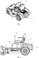
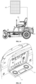
- FIG. 1 shows a power supply system and electric vehicle.
- the electric vehicle may be, but is not limited to, a sitting lawn mower.
- the sitting lawn mower is taken as an example for further explanation.
- the sitting lawn mower includes a vehicle body 100, and a power supply, a driving component, a steering component, a control component, a functional component, an input component, an output component, and the like which are all arranged on the vehicle body 100.
- the power supply may be configured as a battery.
- the power supply may be a lithium battery.
- the driving component may be configured as a motor.
- the functional component may be configured as a mowing cutterhead driven by the motor.
- the input component and the output component 200 are both mounted outside the vehicle body.
- the input component is configured to be connected to external energy source, which can charge the lithium battery of the sitting lawn mower.
- the output component 200 is provided with a port configured to be electrically connected to external equipment, thereby supplying power to the external equipment.
- the external equipment may be a tablet, a mobile phone, a power bank, or the like.
- the three output components may be arranged at different positions outside the sitting lawn mower.
- the three output components 200 are respectively arranged at a rear part, a side part, and a top behind a seat of the lawn mower.
- the output component 200b is located at the rear part of the lawn mower;
- the output component 200c is located at the side part of the lawn mower;
- the output component 200a is located at the top behind the seat of the lawn mower.
- positions below the seat, on a surface of a pedal, on armrests next to the seat, and the like that are not shown in FIG. 2 can also be used to arrange output components 200.
- This embodiment takes the output component 200b arranged at the rear part of the vehicle body 100 as an example for further explanation.
- FIG. 3 is a schematic diagram of a control system of a power supply system and electric vehicle.
- the battery of the lawn mower is simultaneously connected to an alternating current (AC) input, an AC output, a direct current (DC) input, a DC output, other inputs, other outputs, and functional modules.
- AC alternating current
- DC direct current
- other inputs may include a photovoltaic panel input and the like, and other outputs may include an output of wireless charging equipment.
- the functional modules may include electronic components such as a driving module and a cutting module that require electric energy on the lawn mower.
- FIG. 4 A block diagram shown in FIG. 4 is used to explain a power supply system inside the electric vehicle.
- the power supply system inside the lawn mower includes a battery, an inverter, and a control module.
- the battery is electrically connected to the inverter, and the inverter is electrically connected to the AC input.
- the AC input may be configured to be connected to a connecting port of alternating current charging equipment.
- the control module is electrically connected to the inverter, and the control module is electrically connected to the AC output and the DC output to output electric energy.
- the battery itself can be directly electrically connected to the DC output, and a necessary electronic element can be arranged to adjust output parameters. This embodiment will not describe this in detail.
- the battery is electrically connected to the control module, and the control module can obtain battery parameters and is configure to: display a battery usage state and control the battery and other functional units.
- Both the battery and the control module can be electrically connected to the DC input, and the DC input charges the battery by connecting to DC charging equipment.
- Other elements that require electric energy in the lawn mower can obtain electric energy by being directly connected to the battery or electrically connected to the control module.
- Other elements include but are not limited to a driving motor, light source equipment, sound equipment, loudspeaker, and the like.
- the photovoltaic panel arranged on the vehicle body can charge the battery.
- the inverter portion of the lawn mower is connected to MPPT.
- the MPPT is connected to and arranged at an input interface on the lawn mower. After the external photovoltaic panel is connected to the input interface, the battery of the lawn mower can be charged. In this way, the solar energy is used reasonably, the energy utilization efficiency can be improved, and the operation cost can be reduced.
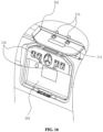
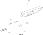
- the output component 200 is arranged at the rear part of the vehicle body 100.
- the output component 200 includes an output panel 201 and a cover body arranged outside the output panel 201.
- the cover body may cover the output panel 201 and play a protection role.
- the cover may be a single independent cover body or a combination of a plurality of cover bodies.
- the two cover bodies are an upper cover 202 and a lower cover 203.
- the two cover bodies are arranged at the top and bottom relative to the rear of the vehicle.
- the upper cover 202 is located above the lower cover 203, and the two cover bodies may be opened independently in opposite directions.
- one side of the upper cover 202 away from the lower cover 203 is rotatably connected to the rear of the vehicle; and one side of the lower cover 203 away from the upper cover is rotatably connected to the rear of the vehicle.
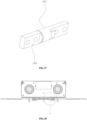
- both the upper cover 202 and the lower cover 203 are at a position of closing the output panel 201
- one side of the upper cover 202 close to the lower cover 203 is docked to one side of the lower cover 203 close to the upper cover 202, so that the upper cover and the lower cover cooperate to achieve an effect of protecting the output panel 201.
- a groove may be arranged in a middle position of the side of the upper cover 202 close to the lower cover 203, and a groove may also be arranged in a middle position on the side of the lower cover 203 close to the upper cover 202.
- An operator can put the fingers into the grooves, so that slippage can be avoided in processes of opening and closing the upper cover 202 or the lower cover 203, and the operation is convenient and quick.
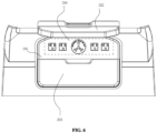
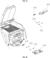
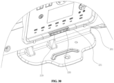
- FIG. 6 shows a state where only the upper cover 202 is opened. In this state, an upper region of the output panel 201 is exposed. This region is an alternating current output region 204. Alternating current output ports can be arranged in this region.
- the alternating current output ports may include a 110 V output port, a 120 V output port, and a 220 V output port.
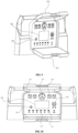
- FIG. 7 and FIG. 8 show a state where only the lower cover 203 is opened. In this state, a lower region of the output panel 201 is exposed. This region is a direct current output region 205. Direct current output ports can be arranged in this region.
- the direct current output ports can include a USB port, a Type-C port, a DC5521 port, a cigarette lighter socket 208, and the like.
- a display element 206 and a switch button 207 are arranged on the output panel 201.
- the display element 206 is configured to display a battery usage state.
- the switch button 207 is configured to control turning on and turning off of the output component 200.
- the switch button 207 may be configured to control turning on and turning off of the display element 206 and/or the output ports. It should be understood that the switch button 207 may be a touch key, a button, a knob, or the like.
- a 120 V socket 209 and a 125 V socket 210 are arranged in the alternating current output region 204 of the output panel 201.
- the 125 V socket 210 may output current of 30 A and is configured to supply power to a recreational vehicle.
- a Type-A port 211, a Type-C port 212, a DC5521 port, and a cigarette lighter socket 208 are arranged in the direct current output region 205 of the output panel 201.
- the display element 206 and the switch button 207 are arranged in a region that can be covered by the lower cover 203 on the output panel 201.
- a groove is arranged on the output panel 201.
- the alternating current output ports, the direct current output ports, the display element 206, the switch button 207, and the like are all arranged on a groove bottom wall of the groove. In this way, after the upper cover 202 and the lower cover 203 are closed, a size of the electric vehicle in a lengthwise direction can be reduced. Meanwhile, the alternating current output ports, the direct current output ports, the display element 206, the switch button 207, and the like are hidden in the groove, making them less likely to collide with objects in an external environment and difficult to damage.
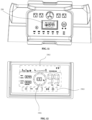
- a display region of the display element 206 includes a battery state display region 2061, another state display region 2062, and an output state display region 2063.
- the battery state display region 2061 is located in the middle of the display region.
- the battery state display region 2061 is configured to display parameters such as a battery level and usable time.
- the battery state display region may also display input power, output power, and whether the input power and the output power are overloaded.
- the another state display region 2062 and the output state display region 2063 are located on an upper side and a lower side of the battery state display region 2061 respectively.
- the output state display region 2063 displays a working state of an output port; the working state includes: whether the output port is faulty and whether the output port is in use, and each type of port may be indicated by a separate icon.
- the another state display region 2062 is configured to display other information except information contained in the battery state display region 2061 and the output state display region 2063, specifically including a battery temperature, an ambient temperature, a state of a heat dissipater, a volume of sound source equipment, charging time, a Bluetooth connection state, a wireless connection state, and the like.
- the input component is arranged on a housing of the vehicle body 100, and the input component includes a cover plate 301.
- the cover plate 301 is movably connected to the housing to switch between an opened state and a closed state.
- the cover body 301 may be rotatably connected to the housing. After the cover plate is rotatably opened, the alternating current input interfaces and the direct current input interfaces may be exposed. Similarly, after the cover plate is rotatably closed, the alternating current input interfaces and the direct current input interfaces may be blocked. In this embodiment, optionally, there may be one alternating current input interface and a plurality of direct current input interfaces.
- the plurality of direct current input interfaces are arranged around the alternating current input interface, namely, the plurality of direct current inputs are arranged at a periphery of the alternating current input interface at intervals.
- the direct current input interfaces include a port connected to the photovoltaic panel.
- the photovoltaic panel may be connected to the vehicle body 100 through the direct current input interface, and the battery is charged using the photovoltaic panel.
- the photovoltaic panel may be placed in a storage space of the vehicle body 100 or fixedly arranged on the exposed housing of the vehicle body 100, for example, in a space above the rear part of the vehicle body 100.
- a foldable photovoltaic panel can be used.
- the photovoltaic panel can be used to charge the battery of the vehicle body 100 to help a user get out of trouble.
- an upper cover 202 and a lower cover 203 are also arranged outside the output panel 201.
- a wireless charging element 213 is further arranged on an inner side of the lower cover 203 and is configured to wirelessly charge electronic equipment.
- a light source component 214 is arranged on an inner side of the upper cover 202 and is configured for lighting.
- the light source component 214 may be a light-emitting diode (LED) lamp or another light-emitting element.
- the upper cover 202 and the lower cover 203 are both hollow.
- the wireless charging element 213 and the light source component 214 are arranged in inner chambers of the upper cover 202 and the lower cover 203. Meanwhile, wires can be arranged through a hinge at a connection between the upper cover 202 and the output panel 201 and a hinge at a connection between the lower cover 203 and the output panel 201.
- This hinge connection and routing mode is relatively common in electronic equipment, and will not be described in detail in this embodiment.
- a pull rod or another component may be further added at a connection of the lower cover 203, so that the stability after opening can be improved.
- the lower cover can be at a zero-degree angle with a horizontal plane, which means that after the lower cover 203 is opened, the lower cover is basically parallel to the horizontal plane.
- an inner side plane of the lower cover 203 faces upwards and is horizontally, making it convenient for electronic equipment such as a mobile phone to be placed on the inner side plane of the lower cover 203 for charging.
- the electronic equipment is placed horizontally and fits stably with the lower cover 203, so that the electronic equipment is hard to fall off and is safe and reliable.
- a positioning groove may be further arranged on the inner side plane of the lower cover 203, and the wireless charging element 213 is arranged in the positioning groove.
- a limiting column may be further arranged on the inner side plane of the lower cover 203, and electronic equipment to be charged may be arranged on the inner side plane and in contact with the limiting column.
- the limiting column can play a role of limiting the position of the electronic equipment and avoid the electronic equipment from sliding off.
- There may be a plurality of limiting columns that are arranged annularly. The electronic equipment to be charged is located in a region encircled by the plurality of limiting columns.
- the limiting column may alternatively be configured as an elastic column.
- the elastic column is in elastic contact with the electronic equipment to be charged, so that this has little wear, difficultly scratches the electronic equipment, and is used safely and reliably. Moreover, since the limiting column is the elastic column, the limiting column can generate deformation, so as to adapt to clamp and position electronic equipment with different sizes.
- the limiting column has a wide range of application and a good limiting effect.
- opening and closing angles of the upper cover 202 and the lower cover 203 there is a certain limitation on opening and closing angles of the upper cover 202 and the lower cover 203.
- the opening and closing angle of the lower cover 203 does not exceed 180 degrees.
- the inner side plane of the lower cover 203 remains horizontal with a forward motion direction of the vehicle body 100 in the maximum opening and closing state of the lower cover 203.
- a maximum opening and closing angle of the upper cover 202 does not exceed 270 degrees.
- the opening and closing angle of the upper cover 202 does not exceed 180 degrees, or when the upper cover 202 is opened and closed to a vertical state, the upper cover can be fixed through a limiting structure.
- the limiting structure includes a positioning buckle arranged on a hinge connecting the upper cover 202 to the vehicle body 100, or an additional bracket.
- the bracket can be used to keep fixing the upper cover.
- the lower cover 203 when the lower cover 203 is rotated to the maximum opening and closing state, the lower cover may also be positioned through the positioning buckle or bracket, thereby improving the stability.
- an inclination angle of the upper cover 202 and/or the lower cover 203 may be detected to determine the opened and closed states of the upper cover 202 and/or the lower cover 203.
- the Hall sensor When the Hall sensor is used, the Hall sensor and a magnetic material may be arranged on the upper cover 202 and the output panel 201 respectively. Whether the upper cover 202 is separated from the output panel 201 may be determined by detecting parameters of the Hall sensor, thereby determining the opened state of the upper cover 202.
- the lower cover 203 may also be detected using the same mode.
- a sensor may be arranged on the upper cover 202 and is configured to be linked with a turn-on switch of the light source component 214, which means that when the sensor on the upper cover 202 obtains that the upper cover 202 is opened to a preset angle, the light source component 214 is directly turned on.
- a sensor may be arranged on the lower cover 203 and is configured to be linked with a turn-on switch of the wireless charging element 213, which means that when the sensor on the lower cover 203 obtains that the lower cover 203 is opened to a preset angle, the wireless charging element 213 is directly turned on.
- sensors may be simultaneously arranged on the upper cover 202 and the lower cover 203 to correspondingly obtain opening angles of the upper cover 202 and the lower cover 203, thereby controlling an electronic element.
- a locking component may be further arranged between the cover body and the output panel 201 to position the cover body.
- a first suction accessory 215 and a second suction accessory 216 are respectively correspondingly arranged on the upper cover 202 and the output panel 201, so that the upper cover and the output panel are magnetically sucked.
- the upper cover 202 is sucked and fixed by the first suction accessory 215 and the second suction accessory 216 when it is closed.
- a magnetic suction structure may be used between the lower cover 203 and the output panel 201 to lock the lower cover 203 when the lower cover is at the closed position.
- both the first suction accessory 215 and the second suction accessory 216 may be configured as strong magnets.
- first suction accessories 215 and two second suction accessories 216 there are two first suction accessories 215 and two second suction accessories 216.
- the first suction accessories 215 are located on one side of the upper cover 202 close to the lower cover 203.
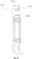
- the lower cover 203 is further provided with a transparent view element 217 and an auxiliary switch 218.
- the transparent view element 217 is made of a transparent material.
- the auxiliary switch 218 is configured to control turning on and turning off of the output component 200.
- the auxiliary switch 218 may be configured to control turning on and turning off of the display element 206 and/or the output ports.
- the auxiliary switch 218 may be an independent electronic switch.
- the auxiliary switch 218 may alternatively be a component that can slide relative to the lower cover 203. When the lower cover 203 is closed, the auxiliary switch 218 is pushed to slide relative to the lower cover 203 to an end portion to be in contact with the switch button 207 on the output panel 201, thereby controlling the switch button 207.
- a voice module may be further arranged in the lawn mower.
- the voice module is configured to receive external sound information.
- the voice module may further process the received external sound information and generate, after the processing, a control instruction to control the display component 206 and control turning on and turning off of an alternating current output interface and a direct current output interface.
- This embodiment also provides a power supply system and electric vehicle.
- This embodiment is a further improvement on the technical solutions of Embodiment I and Embodiment II. To avoid repeated descriptions, the technical solutions of Embodiment I and Embodiment II that have been disclosed will not be explained in detail in this embodiment.
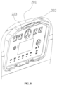
- This embodiment mainly explains connection structures between the upper cover, as well as the lower cover, and the output panel. As shown in FIG. 18 and FIG. 19 , the output panel 201 at the rear part of the vehicle body 100 is movably connected to the upper cover 202 and the lower cover 203.
- FIG. 20 shows a schematic exploded diagram of a connection structure between the upper cover 202 and the output panel 201, as well as a connection structure between the lower cover 203 and the output panel 201.
- Both the upper cover 202 and the lower cover 203 are movably connected to the output panel 201 through wrapping members 219, rotating members 220, and fixing members 221.
- the connection structure between the upper cover 202 and the output panel 201 and the connection structure between the lower cover 203 and the output panel 201 are the same.
- mounting windows 222 and mounting seats 223 are arranged at positions, corresponding to the upper cover 202 and the lower cover 203, on the output panel 201.
- a mounting window 222 and a mounting seat 223 are arranged at a mounting position, corresponding to the upper cover 202, on an upper side of the output panel 201
- a mounting window 222 and a mounting seat 223 are arranged at a mounting position, corresponding to the lower cover 203, on a lower side of the output panel 201.
- the mounting window 222 is a strip-shaped open slot that penetrates through the output panel 201.
- FIG. 22 shows an exploded diagram of the connection structure of the lower cover 203
- FIG. 23 shows an exploded diagram of the connection structure of the upper cover 202.
- the connection structures for mounting the upper cover 202 and the lower cover 203 are set to be the same. To avoid repeated descriptions, this embodiment takes one connection structure as an example for explanation.
- the connecting structure includes a wrapping member 219, a rotating member 220, and a fixing member 221.
- the mounting seats 223 include a rotary mounting seat 2231 and a fixed mounting seat 2232, and the rotary mounting seat 2231 is arranged close to the mounting window 222.
- FIG. 26 shows a specific structure of the fixing member 221.
- the fixing member 221 is provided with a fixing seat 2211 and is configured to be connected to the fixed mounting seat 2232.
- FIG. 27 shows a specific structure of the rotating member 220.
- the rotating member 220 includes a first rotating portion 2201 and a second rotating portion 2202.
- the first rotating portion 2201 and the second rotating portion 2202 are movably connected, and the first rotating portion 2201 and the second rotating portion 2202 may rotate relative to each other around the same rotation axis.
- the first rotating portion 2201 and the second rotating portion 2202 are each provided with a mounting hole and are configured to be fixedly connected to a connecting seat 224 and the rotary mounting seat 2231, respectively.
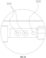
- FIG. 28 shows a sectional diagram of a connecting portion during connection between the lower cover 203 and the output panel 201
- FIG. 29 shows a schematic diagram of a partially enlarged structure in FIG. 28
- a connection mode of the upper cover 202 is basically the same as that of the lower cover 203.
- the connection portion of the lower cover 203 may be taken as an example for further explanation.
- the mounting hole on the first rotating portion 2201 is docked to a hole on the connecting seat 224 in the lower cover 203, and is fixed and connected by a bolt, a screw, a rivet, or the like.
- the mounting hole on the second rotating portion 2202 is docked to a hole on the rotary mounting seat 2231 in the output panel 201, and is fixed and connected by a bolt/screw/rivet.
- the fixing seat 2211 on the fixing member 221 is docked to the fixed mounting seat 2232 in the output panel 201.
- a mounting direction of the fixing member such as the bolt/screw/rivet that fixes the second rotating portion 2202 is opposite to a mounting direction of the fixing member 221.
- the lower cover 203 is connected to the wrapping member 219 through a buckle/bolt or in another way to form a chamber for wrapping the rotating member 220.
- the lower cover 203 is fixedly connected to the wrapping member 219 through the buckle.
- the wrapping member 219 after being mounted, the wrapping member 219 also covers a space of the mounting window 222.
- both the wrapping member 219 and the lower cover 203 are provided with routing notches 230 configured for wiring arrangement.
- Wiring harnesses required to be connected to the electronic components in the lower cover 203 are introduced into the vehicle body 100 through the routing notches 230 and are connected to the relevant electronic components.
- the upper cover 202 is also provided with a routing notch 230 configured for wiring arrangement, so as to reduce a length of a wiring harness and facilitate wire arrangement.
- an auxiliary switch 218 is arranged on the lower cover 203.
- the lower cover 203 includes a housing 2031 and a bottom plate 2032.
- the auxiliary switch 218 is movably connected to the lower cover 203, and an elastic member is arranged between the housing 2031 and the bottom plate 2032 to provide potential energy for the auxiliary switch 218 to move towards an outer side of the housing 2031.
- the elastic member is always in a compressed state, which can make the auxiliary switch 218 have a trend to move in a direction from the bottom plate 2032 to the housing 2031.
- the elastic member may be a spring 225.
- the auxiliary switch 218 moves towards the output panel 201 and can be in contact with the switch button 207 on the output panel 201 to control the switch button 207. After the auxiliary switch 218 is released, under the action of the elastic member, the auxiliary switch 218 is reset, and the auxiliary switch 218 is separated from the switch button 207 on the output panel 201.
- a limiting protrusion is arranged on the housing 2031.
- the auxiliary switch 218 is provided with an abutment protrusion.
- the abutment protrusion is in contact with one side of the limiting protrusion close to the bottom plate 2032. Therefore, under an elastic force of the elastic member, the auxiliary switch 218 may not be separated from the housing 2032.
- a cavity is arranged inside the vehicle body 100.
- the cavity can accommodate a battery pack and other relevant electronic elements, such as the inverter and the MPPT assembly.
- the vehicle body 100 includes a frame 101 that plays a supporting role.
- a vertical rear bracket 102 is arranged at a rear end of the frame 101, and a rear covering member 103 is mounted on the rear bracket 102.
- the output panel 201 is located on the rear covering member 103.
- an auxiliary bracket 228 is further arranged at the rear end of the frame 101, and a bottom end of the auxiliary bracket 228 is fixedly connected to the frame 101.
- the entire auxiliary bracket 228 is of a closed ringlike structure, and its contour is close to an outer contour of the output panel 201.
- a plurality of connecting points are uniformly arranged at a circle of the outer contour of the auxiliary bracket 228, and the plurality of connecting points are simultaneously fixedly connected to the rear covering member 103.
- a space between adjacent connecting points does not exceed 20 cm.
- the structural setting of the auxiliary bracket 228 can improve the overall strength of the output panel 201 and reduce the deformation of the output panel during use.
- Interfaces and electronic elements related to the output panel 201 are integrated on a PCB 227.
- the PCB 227 is fixedly connected to an inner side of rear covering member 103.
- the PCB 227 is located in an inner circle enclosed by the auxiliary bracket 228.
- a cooling element 226 is further arranged in the cavity of the vehicle body 100. The cooling element 226 is configured to cool the PCB 227.
- the cooling element 226 may be a cooling fan.
- a distance between the PCB 227 and an edge of a battery pack 104 is not less than 5 cm.
- the distance between the PCB 227 and the edge of the battery pack 104 is set to 10 cm.
- the cooling element 226 is the cooling fan, the cooling element 226 is placed in a manner of being staggered from a cooling fan in the battery pack 104.
- the power supply system and the electric vehicle provided in this embodiment have diversified functions, are used conveniently and flexibly, and has a wide range of application.
Landscapes
- Engineering & Computer Science (AREA)
- Power Engineering (AREA)
- Life Sciences & Earth Sciences (AREA)
- Environmental Sciences (AREA)
- Transportation (AREA)
- Mechanical Engineering (AREA)
- Sustainable Energy (AREA)
- Sustainable Development (AREA)
- Physics & Mathematics (AREA)
- Acoustics & Sound (AREA)
- Multimedia (AREA)
- Computer Networks & Wireless Communication (AREA)
- Charge And Discharge Circuits For Batteries Or The Like (AREA)
Applications Claiming Priority (2)
| Application Number | Priority Date | Filing Date | Title |
|---|---|---|---|
| CN202311012952 | 2023-08-13 | ||
| PCT/CN2023/142319 WO2025035682A1 (zh) | 2023-08-13 | 2023-12-27 | 一种电源系统及电动载具 |
Publications (2)
| Publication Number | Publication Date |
|---|---|
| EP4535604A1 true EP4535604A1 (de) | 2025-04-09 |
| EP4535604A4 EP4535604A4 (de) | 2026-04-29 |
Family
ID=90749792
Family Applications (1)
| Application Number | Title | Priority Date | Filing Date |
|---|---|---|---|
| EP23931189.7A Pending EP4535604A4 (de) | 2023-08-13 | 2023-12-27 | Stromversorgungssystem und elektrofahrzeug |
Country Status (5)
| Country | Link |
|---|---|
| EP (1) | EP4535604A4 (de) |
| CN (3) | CN117918128A (de) |
| AU (1) | AU2023433478A1 (de) |
| CA (1) | CA3247948A1 (de) |
| WO (1) | WO2025035682A1 (de) |
Family Cites Families (14)
| Publication number | Priority date | Publication date | Assignee | Title |
|---|---|---|---|---|
| JP2007295684A (ja) * | 2006-04-24 | 2007-11-08 | Sanyo Electric Co Ltd | ポータブル電源装置 |
| KR20080065798A (ko) * | 2007-01-10 | 2008-07-15 | 강현철 | 다기능 파워팩 |
| US20120024552A1 (en) * | 2010-07-30 | 2012-02-02 | Hitachi Koki Co., Ltd. | Inverter Device and Electrical Power Tool |
| CN202602352U (zh) * | 2012-04-19 | 2012-12-12 | 中国人民解放军第三二三医院 | 一种基于薄膜太阳能电池野战便携式多功能应急电源 |
| WO2015143088A1 (en) * | 2014-03-19 | 2015-09-24 | Motivo Engineering LLC | Mobile power conversion and distribution system |
| CN104505848A (zh) * | 2014-12-18 | 2015-04-08 | 北京四方继保自动化股份有限公司 | 基于分布式能源交直流混合接入的储能电源装置 |
| CN206041585U (zh) * | 2016-09-27 | 2017-03-22 | 北京飞亚视科技发展有限公司 | 一种多功能便携式锂电源箱 |
| CN208656493U (zh) * | 2018-08-07 | 2019-03-26 | 深圳市中科能电子技术有限公司 | 一种太阳能应急电源 |
| CN211530818U (zh) * | 2020-04-10 | 2020-09-18 | 深圳市华信通高科技有限公司 | 一种移动应急电源接入装置 |
| CN111532156A (zh) * | 2020-05-15 | 2020-08-14 | 戴姆勒股份公司 | 用于控制充电连接装置的方法、控制装置及车辆 |
| CN214755612U (zh) * | 2021-04-08 | 2021-11-16 | 东莞市超凡锂能科技有限公司 | 多功能便携式储能电源 |
| CN216290240U (zh) * | 2021-09-13 | 2022-04-12 | 深圳市泰德炜电子科技有限公司 | 一种多功能户外正弦波逆变移动储能电源 |
| CN218386814U (zh) * | 2022-09-30 | 2023-01-24 | 格力博(江苏)股份有限公司 | 能源站系统及能源站 |
| CN219247498U (zh) * | 2022-11-22 | 2023-06-23 | 宁波甬菲特电子科技有限公司 | 一种户外电源 |
-
2023
- 2023-12-27 CN CN202311819578.5A patent/CN117918128A/zh active Pending
- 2023-12-27 EP EP23931189.7A patent/EP4535604A4/de active Pending
- 2023-12-27 CA CA3247948A patent/CA3247948A1/en active Pending
- 2023-12-27 WO PCT/CN2023/142319 patent/WO2025035682A1/zh active Pending
- 2023-12-27 AU AU2023433478A patent/AU2023433478A1/en active Pending
- 2023-12-27 CN CN202311820084.9A patent/CN118383148A/zh active Pending
- 2023-12-27 CN CN202311819830.2A patent/CN118216313A/zh active Pending
Also Published As
| Publication number | Publication date |
|---|---|
| WO2025035682A1 (zh) | 2025-02-20 |
| CA3247948A1 (en) | 2025-07-09 |
| CN118383148A (zh) | 2024-07-26 |
| CN118216313A (zh) | 2024-06-21 |
| AU2023433478A1 (en) | 2025-02-27 |
| EP4535604A4 (de) | 2026-04-29 |
| CN117918128A (zh) | 2024-04-26 |
Similar Documents
| Publication | Publication Date | Title |
|---|---|---|
| US10583504B2 (en) | Tabletop cutting device | |
| JP7027490B2 (ja) | 電動工具 | |
| EP2711228A1 (de) | Steuermodul für einen elektrischen Rollstuhl | |
| EP3892081B1 (de) | Aufsitzrasenmäher | |
| EP3736483A1 (de) | Handhaltbare gimbal-vorrichtung | |
| US11027344B2 (en) | Cutting device | |
| WO2013027599A1 (ja) | 電源装置 | |
| US20240077181A1 (en) | Elevated lighting device and storage system | |
| US5673173A (en) | Portable computer having a modular power conversion unit | |
| EP4535604A1 (de) | Stromversorgungssystem und elektrofahrzeug | |
| CN210469313U (zh) | 一种便携式手持控制器 | |
| JP2013046512A (ja) | 電源装置 | |
| WO2018225379A1 (ja) | せん孔装置 | |
| CN219165151U (zh) | 一种骑乘式割草机 | |
| JP2018043372A (ja) | 携帯用加工機 | |
| CN114110459B (zh) | 一种可栓接固定的近远光手电筒 | |
| CN224184212U (zh) | 车载支架 | |
| CN114110458B (zh) | 一种可适配多种充电接口的近远光手电筒 | |
| CN119481363A (zh) | 电池包 | |
| CN114110456B (zh) | 一种近远光手电筒 | |
| CN224007947U (zh) | 一种拉杆机构及电动行李箱 | |
| CN223599520U (zh) | 车载充电支架 | |
| CN223589424U (zh) | 一种触摸手指机器人组件 | |
| CN221113728U (zh) | 车载充电支架 | |
| WO2025169829A1 (ja) | アダプタ、アダプタシステム、電池パック、及び、電気機器システム |
Legal Events
| Date | Code | Title | Description |
|---|---|---|---|
| STAA | Information on the status of an ep patent application or granted ep patent |
Free format text: STATUS: UNKNOWN |
|
| STAA | Information on the status of an ep patent application or granted ep patent |
Free format text: STATUS: THE INTERNATIONAL PUBLICATION HAS BEEN MADE |
|
| PUAI | Public reference made under article 153(3) epc to a published international application that has entered the european phase |
Free format text: ORIGINAL CODE: 0009012 |
|
| STAA | Information on the status of an ep patent application or granted ep patent |
Free format text: STATUS: REQUEST FOR EXAMINATION WAS MADE |
|
| 17P | Request for examination filed |
Effective date: 20241010 |
|
| AK | Designated contracting states |
Kind code of ref document: A1 Designated state(s): AL AT BE BG CH CY CZ DE DK EE ES FI FR GB GR HR HU IE IS IT LI LT LU LV MC ME MK MT NL NO PL PT RO RS SE SI SK SM TR |
|
| RIC1 | Information provided on ipc code assigned before grant |
Ipc: H02J 7/00 20060101AFI20251223BHEP Ipc: H02J 9/00 20060101ALI20251223BHEP Ipc: B60K 15/05 20060101ALI20251223BHEP Ipc: B60L 50/60 20190101ALI20251223BHEP Ipc: B60L 53/16 20190101ALI20251223BHEP |