EP4535520A1 - Knopfzelle und elektronische vorrichtung - Google Patents
Knopfzelle und elektronische vorrichtung Download PDFInfo
- Publication number
- EP4535520A1 EP4535520A1 EP22949803.5A EP22949803A EP4535520A1 EP 4535520 A1 EP4535520 A1 EP 4535520A1 EP 22949803 A EP22949803 A EP 22949803A EP 4535520 A1 EP4535520 A1 EP 4535520A1
- Authority
- EP
- European Patent Office
- Prior art keywords
- virtual line
- button cell
- region
- edge
- electrode plate
- Prior art date
- Legal status (The legal status is an assumption and is not a legal conclusion. Google has not performed a legal analysis and makes no representation as to the accuracy of the status listed.)
- Pending
Links
Images


Classifications
-
- H—ELECTRICITY
- H01—ELECTRIC ELEMENTS
- H01M—PROCESSES OR MEANS, e.g. BATTERIES, FOR THE DIRECT CONVERSION OF CHEMICAL ENERGY INTO ELECTRICAL ENERGY
- H01M50/00—Constructional details or processes of manufacture of the non-active parts of electrochemical cells other than fuel cells, e.g. hybrid cells
- H01M50/10—Primary casings; Jackets or wrappings
- H01M50/102—Primary casings; Jackets or wrappings characterised by their shape or physical structure
- H01M50/109—Primary casings; Jackets or wrappings characterised by their shape or physical structure of button or coin shape
-
- H—ELECTRICITY
- H01—ELECTRIC ELEMENTS
- H01M—PROCESSES OR MEANS, e.g. BATTERIES, FOR THE DIRECT CONVERSION OF CHEMICAL ENERGY INTO ELECTRICAL ENERGY
- H01M10/00—Secondary cells; Manufacture thereof
- H01M10/05—Accumulators with non-aqueous electrolyte
- H01M10/058—Construction or manufacture
- H01M10/0587—Construction or manufacture of accumulators having only wound construction elements, i.e. wound positive electrodes, wound negative electrodes and wound separators
-
- H—ELECTRICITY
- H01—ELECTRIC ELEMENTS
- H01M—PROCESSES OR MEANS, e.g. BATTERIES, FOR THE DIRECT CONVERSION OF CHEMICAL ENERGY INTO ELECTRICAL ENERGY
- H01M50/00—Constructional details or processes of manufacture of the non-active parts of electrochemical cells other than fuel cells, e.g. hybrid cells
- H01M50/50—Current conducting connections for cells or batteries
- H01M50/531—Electrode connections inside a battery casing
- H01M50/533—Electrode connections inside a battery casing characterised by the shape of the leads or tabs
-
- Y—GENERAL TAGGING OF NEW TECHNOLOGICAL DEVELOPMENTS; GENERAL TAGGING OF CROSS-SECTIONAL TECHNOLOGIES SPANNING OVER SEVERAL SECTIONS OF THE IPC; TECHNICAL SUBJECTS COVERED BY FORMER USPC CROSS-REFERENCE ART COLLECTIONS [XRACs] AND DIGESTS
- Y02—TECHNOLOGIES OR APPLICATIONS FOR MITIGATION OR ADAPTATION AGAINST CLIMATE CHANGE
- Y02E—REDUCTION OF GREENHOUSE GAS [GHG] EMISSIONS, RELATED TO ENERGY GENERATION, TRANSMISSION OR DISTRIBUTION
- Y02E60/00—Enabling technologies; Technologies with a potential or indirect contribution to GHG emissions mitigation
- Y02E60/10—Energy storage using batteries
-
- Y—GENERAL TAGGING OF NEW TECHNOLOGICAL DEVELOPMENTS; GENERAL TAGGING OF CROSS-SECTIONAL TECHNOLOGIES SPANNING OVER SEVERAL SECTIONS OF THE IPC; TECHNICAL SUBJECTS COVERED BY FORMER USPC CROSS-REFERENCE ART COLLECTIONS [XRACs] AND DIGESTS
- Y02—TECHNOLOGIES OR APPLICATIONS FOR MITIGATION OR ADAPTATION AGAINST CLIMATE CHANGE
- Y02P—CLIMATE CHANGE MITIGATION TECHNOLOGIES IN THE PRODUCTION OR PROCESSING OF GOODS
- Y02P70/00—Climate change mitigation technologies in the production process for final industrial or consumer products
- Y02P70/50—Manufacturing or production processes characterised by the final manufactured product
Definitions
- This application relates to the field of energy storage technology, particularly to a button cell and an electronic device.
- a button cell is a device that converts external energy into electrical energy and stores it internally, to power external devices (such as portable electronic devices) when needed.
- a button cell includes a housing, an electrode assembly accommodated in the housing, and tabs.
- the electrode assembly includes a first electrode plate, a second electrode plate, and a separator.
- the first electrode plate and the second electrode plate have opposite polarities, and a separator is disposed between them for separation.
- the electrode assembly is wound in a spiral shape to be accommodated in a cylindrical housing.
- the inventors of this application have discovered that: when viewed along the central axis of the wound electrode assembly in a button cell, the dimensions from the central axis to various edges of the electrode assembly are uneven, resulting in uneven pressures on different parts of the electrode assembly during manufacturing and use. This leads to poor interfaces between the first electrode plate and the second electrode plate, resulting in a relatively low capacity retention rate after a preset number of charge and discharge cycles, and affecting the service life of the button cell.
- the third virtual line is located in the fourth region, and the fourth virtual line is located in the second region.
- This arrangement makes the third virtual line and the fourth virtual line located in opposite regions and not in the same region as the first virtual ray, with a relatively large distance between them, which helps to improve the overall flatness of the button cell.
- the second current collector includes a second starting edge and a second ending edge arranged opposite to each other in the winding direction.
- a ray using the central axis as an endpoint and passing through the first starting edge is defined as a first virtual ray
- a ray using the central axis as an endpoint and passing through the second starting edge is defined as a fifth virtual line
- an included angle between the fifth virtual line and the first virtual ray along the winding direction is ⁇ 2 , where 90° ⁇ 2 ⁇ 180°.
- the first ending edge and the second ending edge are not located in the same region, which helps to alleviate the influence of the terminating ends of the first current collector and the second current collector on the overall flatness of the button cell, and also helps to reduce the impact of the cycling swelling of one of the electrode plates on the reliability of the terminating end of the button cell caused by the first ending edge and the second ending edge being too close to each other.
- mounting includes fixing or limiting an element or apparatus to a specific position or place by welding, screwing, clamping, bonding, or the like.
- the element or apparatus may stay still at the specific position or place, or may move within a limited range. After being fixed or limited to the specific position or place, the element or apparatus can be disassembled or cannot be disassembled. This is not limited in some embodiments of this application.
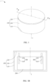
- FIG. 1 is a schematic diagram of a button cell 1 according to an embodiment of this application
- FIG. 1B is a schematic cross-sectional view of a button cell along M-M
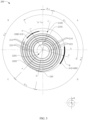
- FIG. 2 is a schematic diagram of an electrode assembly 200 when viewed along a first direction Z
- FIG. 3 is a schematic diagram after the separator in FIG. 2 is hidden.
- the button cell 1 includes an electrode assembly 200, a first tab 300, and a second tab 400.
- the electrode assembly 200 is a core component of the button cell 1 for implementing charge and discharge.
- the first tab 300 is connected to the electrode assembly 200 to form one electrode of the button cell 1; and the second tab 400 is connected to the electrode assembly 200 to form the other electrode of the button cell 1.
- the button cell 1 further includes a housing 100, which is used to accommodate the above-mentioned electrode assembly 200, the first tab 300, the second tab 400, and an electrolyte.
- a housing 100 which is used to accommodate the above-mentioned electrode assembly 200, the first tab 300, the second tab 400, and an electrolyte.
- the specific structures of the housing 100, the electrode assembly 200, the first tab 300, and the second tab 400 are described below in order.
- the housing 100 is cylindrical in shape, and includes a first wall portion 110, a second wall portion 120, and a connecting wall portion 130.
- the first wall portion 110 and the second wall portion 120 are both flat cylindrical, and are arranged opposite each other along a first direction Z as shown.
- the connecting wall portion 130 extends from the first wall portion 110 to the second wall portion 120.
- the first wall portion 110, the second wall portion 120, and the connecting wall portion 130 together enclose an accommodating cavity for accommodating the electrode assembly 200, the first tab 300, and the second tab 400.
- the electrode assembly 200 is cylindrical in shape, and includes a first electrode plate 210, a second electrode plate 220, and a separator 230.
- the first electrode plate 210, the second electrode plate 220, and the separator 230 are stacked and wound in a spiral shape around a central axis O.
- the separator 230 is disposed between the first electrode plate 210 and the second electrode plate 220 for separation.
- the electrode assembly 200 is cylindrical in shape, and the "central axis" in this application document refers to an axis of the electrode assembly 200 in the wound state; and the "first direction Z" in this application document is an extending direction of the central axis O and perpendicular to a winding direction W of the electrode assembly 200.
- FIG. 2 is a view from the first direction Z.
- the related elements of the button cell appear as planar shapes, for example, the central axis O appears as a point.
- the method for determining the central axis O may be: obtaining an image of the electrode assembly 200 viewed from the first direction Z, and processing the image to draw a circumscribed circle of the electrode assembly 200, where a line extending along the first direction Z from the center of the circumscribed circle is the central axis O.
- the electrode assembly 200 is described by using an example in which the first electrode plate 210 is a cathode plate and the second electrode plate 220 is an anode plate. It can be understood that in other embodiments of this application, the first electrode plate 210 may alternatively be an anode plate, and correspondingly, the second electrode plate 220 is a cathode plate.
- the first electrode plate 210 includes a first current collector 211 and a first active material layer 212 applied on a surface of the first current collector 211.
- the first current collector 211 includes a first starting edge 2101 and a first ending edge 2102 arranged opposite to each other along a second direction X, and two first long edges 2103 arranged opposite to each other along a third direction Y.
- the first electrode plate 210 is wound around the first starting edge 2101, that is, the first electrode plate includes a first starting edge 2101 and a first ending edge 2102 arranged opposite to each other along the winding direction W of the electrode assembly 200 as shown in FIG. 3 .
- the first long edges 2103 extend along the winding direction W
- the first starting edge 2101 is an edge line of the first current collector 211 located at a center position of the first electrode plate 210
- the first ending edge 2102 is an edge line of the first current collector 211 located at an outer turn of the first electrode plate 210.
- the first long edges 2103 extend along the second direction X.
- the first current collector 211 includes a first coated film segment 2111, a first uncoated foil segment 2112, and a second uncoated foil segment 2113. From the first starting edge 2101 to the first ending edge 2102 along the winding direction W of the electrode assembly 200, the first uncoated foil segment 2112, the first coated film segment 2111, and the second uncoated foil segment 2113 are arranged in sequence.
- the first coated film segment 2111 is a region with the first active material layer 212 on both sides.
- the first uncoated foil segment 2112 and the second uncoated foil segment 2113 are regions with at least one side not coated with the first active material layer 212.
- the first starting edge 2101 is arranged as an edge line of the first uncoated foil segment 2112, meaning that the first uncoated foil segment 2112 is located in an inner layer region of the electrode assembly 200 in the wound state.
- the first ending edge 2102 is arranged as an edge line of the second uncoated foil segment 2113, meaning that the second uncoated foil segment 2113 is located in an outer layer region of the electrode assembly 200 in the wound state.
- the "winding direction W" in this application document means an extending direction of the electrode assembly 200 in the wound state from the inside to the outside. For example, when viewed along the first direction Z, the first electrode plate 210 extends from the first starting edge 2101 to the first ending edge 2102 along the winding direction W.
- the second electrode plate 220 includes a second current collector 221 and a second active material layer 222 applied on a surface of the second current collector 221.
- the second current collector 221 includes a second starting edge 2201 and a second ending edge 2202 arranged opposite to each other along the second direction X, and two second long edges 2203 arranged opposite to each other along the third direction Y.
- the second electrode plate 210 is wound around the second starting edge 2201, that is, the second electrode plate includes a second starting edge 2201 and a second ending edge 2202 arranged opposite to each other along the winding direction W of the electrode assembly 200 as shown in FIG. 3 .
- the second long edges 2203 extend along the winding direction W
- the second starting edge 2201 is an edge line of the second current collector 221 located at a center position of the second electrode plate 220
- the second ending edge 2202 is an edge line of the second current collector 221 located at an outer turn of the second electrode plate 220.
- the second long edges 2203 extend along the second direction X.
- the innermost turn of the electrode assembly 200 in the wound state is a part of the second electrode plate 220, that is, when viewed from the first direction Z, one end of the second electrode plate 220 located in the central region of the electrode assembly 200 extends beyond one end of the first electrode plate 210 located in the central region of the electrode assembly 200.
- the outermost turn of the electrode assembly 200 in the wound state is a part of the second electrode plate 220, that is, when viewed from the first direction Z, one end of the second electrode plate 220 facing away from the central region of the electrode assembly 200 extends beyond one end of the first electrode plate 210 facing away from the central region of the electrode assembly 200.
- the second tab 400 is connected to the second electrode plate 220.
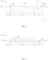
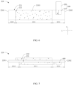
- the second tab 400 includes a second connection segment 410 and a second extension segment 420 arranged in sequence along the first direction Z.
- the second connection segment 410 extends along the first direction Z and is connected to the second current collector 221.
- the second connection segment 410 is connected to the fourth uncoated foil segment 2213.
- the second extension segment 420 is connected to the second connection segment 410 and is located outside the second current collector 221.
- the second connection segment 410 has a second centerline Q extending along the first direction Z. When viewed along the first direction Z, the second centerline Q passes through the midpoint of the second tab 400.
- a ray using the central axis O as an endpoint and passing through the first ending edge 2102 is defined as a sixth virtual line f.
- a ray using the central axis O as an endpoint and passing through the second ending edge 2202 is defined as a seventh virtual line g.
- a smaller included angle formed between the third virtual line c and the fourth virtual line d is ⁇ 1 .
- ⁇ 1 is that included angle.
- An included angle between the fifth virtual line e and the first virtual ray a' along the winding direction W is ⁇ 2 ; an included angle between the sixth virtual line f and the seventh virtual line g along the winding direction W is ⁇ 3 ; and a smaller included angle formed between the first virtual ray a and the sixth virtual line f is ⁇ 4 .
- ⁇ 4 is that included angle.
- a smaller included angle formed between the fifth virtual line e and the seventh virtual line g is ⁇ 5 .
- ⁇ 5 is that included angle.
- the arrangement of the first tab 300 and the second tab 400 easily makes the dimensions of the electrode assembly 200 uneven in various places, which in turn causes the pressure on the surfaces of the first electrode plate 210 and the second electrode plate 220 to be inconsistent at different parts. Consequently, there may be poor interfaces between the first electrode plate 210 and the second electrode plate 220, which affects the cycle life of the button cell 1. Therefore, there should be a proper distance between the first tab 300 and the second tab 400 to reduce the risk of the two being too close and leading to excessive local deformation of the electrode assembly 200.
- the third virtual line c and the fourth virtual line d are not simultaneously located in one of the first region, the second region, the third region, and the fourth region, so that there is a relatively large distance between the first tab 300 and the second tab 400.
- the “included angle between cathode and anode tabs” described in this application document means an included angle between the first tab 300 and the second tab 400 when viewed along the first direction, that is, a smaller included angle between the third virtual line c and the fourth virtual line d, denoted as ⁇ 1 .
- the “included angle between the starting positions of the cathode and anode plates” described in this application document means an included angle formed by the staggered portions of the first electrode plate 210 and the second electrode plate 220 at the head and the central axis O when viewed along the first direction, that is, the included angle of the fifth virtual line e rotating along the winding direction W to the first virtual ray a', denoted as ⁇ 2 .
- the “included angle between the head and tail of the cathode” described in this application document means an included angle formed jointly by the first starting edge 2101, the central axis O, and the first ending edge 2102 of the first electrode plate 210 when viewed along the first direction Z, that is, a smaller included angle formed between the first virtual ray a and the sixth virtual line f, denoted as ⁇ 4 .
- the “included angle between the head and tail of the anode” described in this application document means an included angle formed jointly by the second starting edge 2201, the central axis O, and the second ending edge 2202 of the second electrode plate 220 when viewed along the first direction Z, that is, a smaller included angle formed between the fifth virtual line e and the seventh virtual line g, denoted as ⁇ 5 .
- the cell After a button cell is manufactured, the cell is charged at a constant current of 0.5C to 4.45 V at 25°C, left standing for 30 minutes, and then discharged at 0.5C to 3.0 V. After 500 such charge-discharge cycles, the capacity of the fully discharged cell is C 2 .
- the battery capacity at the first full discharge after manufacturing is C 1 .
- the "capacity retention rate after 500 cycles" described in this application document means a percentage of the battery capacity C 2 to the battery capacity C 1 .
- the "capacity retention rate after 500 cycles" of the button cell 1 is 80%.
- Lithium cobalt oxide, polyvinylidene fluoride, and conductive carbon black (SP) were added into N-methylpyrrolidone (NMP) at a weight ratio of 97:1.5:1.5 and fully stirred and mixed to produce a uniform positive electrode slurry.
- NMP N-methylpyrrolidone
- the positive electrode slurry was applied on both surfaces of a positive current collector (aluminum foil, with a thickness of 12 ⁇ m and a width of 4.0 mm) to form a uniform coating. After drying and cold pressing, the coating thickness was 50 ⁇ m on a single side. Then a conductive plate was welded to the positive electrode plate to obtain a positive electrode plate.
- Graphite material, styrene-butadiene rubber (SBR), and sodium carboxymethyl cellulose (CMC) were added into deionized water at a weight ratio of 97.4:1.2:1.4 and fully stirred an mixed to produce a uniform negative electrode slurry.
- the negative electrode slurry was applied to a negative current collector (copper foil, with a thickness of 10 ⁇ m and a width of 4.5 mm) pre-coated with a primer layer. After drying and cold pressing, the coating thickness was 60 ⁇ m on a single side. Thus, a negative electrode plate was obtained.
- the primer layer was formed by mixing SP, CMC, and SBR at a mass ratio of 60:5:35 and then applying the obtained slurry to two surfaces of the current collector in the gravure coating method. Then a conductive plate was welded to the negative electrode plate to obtain a negative electrode plate.
- the substrate layer of a single-layer film made of polyethylene (PE) was selected as a separator.
- the separator had a thickness of 16 ⁇ m.
- the prepared positive electrode plate, separator, and negative electrode plate were stacked in sequence, so that the separator was sandwiched between the positive electrode plate and the negative electrode plate for separation. Then the resulting stack was wound to obtain an electrode assembly.
- the electrode assembly was placed into the first housing, the second housing was fitted onto the top of the first housing, and moisture removal was performed at 80°C.
- EC ethylene carbonate
- PC propylene carbonate
- DEC diethyl carbonate
- the included angle ⁇ 1 between the cathode and anode tabs was 80°; the included angle ⁇ 2 between the starting positions of the heads of the cathode and anode plates was 120°; the included angle ⁇ 4 between the head and tail of the cathode was 20°; and the included angle ⁇ 5 between the head and tail of the anode was 20°.
- the button cell provided in Example 1 is substantially the same as that in Comparative example 1.
- the main difference from the button cell provided in Comparative example 1 is: in the button cell of Example 1, the included angle ⁇ 1 between the cathode and anode tabs is 90°.
- the button cell provided in Example 2 is substantially the same as that in Comparative example 1.
- the main difference from the button cell provided in Comparative example 1 is: in the button cell of Example 2, the included angle ⁇ 1 between the cathode and anode tabs is 100°.
- the button cell provided in Example 3 is substantially the same as that in Comparative example 1.
- the main difference from the button cell provided in Comparative example 1 is: in the button cell of Example 3, the included angle ⁇ 1 between the cathode and anode tabs is 110°.
- the button cell provided in Example 4 is substantially the same as that in Comparative example 1.
- the main difference from the button cell provided in Comparative example 1 is: in the button cell of Example 4, the included angle ⁇ 1 between the cathode and anode tabs is 120°.
- the button cell provided in Example 5 is substantially the same as that in Comparative example 1.
- the main difference from the button cell provided in Comparative example 1 is: in the button cell of Example 5, the included angle ⁇ 1 between the cathode and anode tabs is 130°.
- the button cell provided in Example 6 is substantially the same as that in Comparative example 1.
- the main difference from the button cell provided in Comparative example 1 is: in the button cell of Example 6, the included angle ⁇ 1 between the cathode and anode tabs is 150°.
- the button cell provided in Example 7 is substantially the same as that in Comparative example 1.
- the main difference from the button cell provided in Comparative example 1 is: in the button cell of Example 7, the included angle ⁇ 1 between the cathode and anode tabs is 180°.
- Table 1 shows the relationship between the relative position relationship between the first tab 300 and the second tab 400 and the capacity retention rate of the button cell 1 after 500 cycles.
- Table 1 shows the relationship between the relative position relationship between the first tab 300 and the second tab 400 and the capacity retention rate of the button cell 1 after 500 cycles.
- the included angle ⁇ 1 between the first tab 300 and the second tab 400 is ⁇ 90°
- the capacity retention rate of the button cell 1 after 500 cycles is significantly lower than 90%
- 90 ⁇ 1 ⁇ 180° the capacity retention rate of the button cell 1 after 500 cycles is close to or higher than 90%, and its service life is longer.
- the setting of 90 ⁇ 1 ⁇ 180° allows for a relatively large distance between the first tab 300 and the second tab 400, which can also reduce the current noise phenomenon caused by the first tab 300 and the second tab 400 being too close to each other.
- Table 1 Relationship between the relative position relationship between the first tab and the second tab and the capacity retention rate of the button cell after 500 cycles Included angle between cathode and anode tabs ⁇ 1 (°) Included angle between starting positions of heads of cathode and anode electrode plates ⁇ 2 (°) Included angle between head and tail of cathode ⁇ 4 (°) Included angle between head and tail of anode ⁇ 5 (°) Capacity retention rate after 500 cycles Comparative example 1 80 120 20 20 79% Example 1 90 120 20 20 20 89% Example 2 100 120 20 20 90% Example 3 110 120 20 20 90% Example 4 120 120 20 20 20 90% Example 5 130 120 20 20 91% Example 6 150 120 20 20 91% Example 7 180 120 20 20 90%
- the first electrode plate 210, the second electrode plate 220, and the separator 230 are stacked in the above stacking manner, and one end of the stacked electrode assembly 200 is wound around a winding mandrel, and then the winding mandrel is rotated to wind the electrode assembly 200 into a spiral shape. If the heads of the first electrode plate 210 and the second electrode plate 220 are flush, or the staggered distance between them is small, it is difficult to wind the electrode assembly 200.
- the end of the second coated film segment 2211 close to the third uncoated foil segment 2212 may not extend beyond the end of the first coated film segment 2111 close to the first uncoated foil segment 2112, which may cause lithium precipitation, and further lead to a low capacity retention rate of the button cell 1 after 500 cycles.
- the button cell provided in Example 11 is substantially the same as that in Example 8.
- the main difference from the button cell provided in Example 8 is: in the button cell of Example 11, the included angle ⁇ 2 between the starting positions of cathode and anode plates is 140°.
- the button cell provided in Example 12 is substantially the same as that in Example 8.
- the main difference from the button cell provided in Example 8 is: in the button cell of Example 12, the included angle ⁇ 2 between the starting positions of cathode and anode plates is 160°.
- Table 2 shows a relationship between the included angle ⁇ 2 and the capacity retention rate of the button cell 1 after 500 cycles.
- ⁇ 2 ⁇ 90° it is difficult to wind the electrode assembly 200 using a winding mandrel, there is slight lithium precipitation at the head of the second electrode plate 220, and the cycling capacity retention rate of the button cell 1 after 500 cycles is lower than 90%.
- 90° ⁇ 2 ⁇ 180° it is easy to wind the electrode assembly 200 using a winding mandrel, there is no lithium precipitation at the head of the second electrode plate 220, and the cycling capacity retention rate of the button cell 1 after 500 cycles is close to or higher than 90%.
- the first connection segment 310 and the second connection segment 410 are both spaced from the fifth virtual line e. If the first connection segment 310 and the second connection segment 410 both intersect with the fifth virtual line e, the arrangement of the first tab 300 and the second tab 400 causes compressive stress on the electrode assembly 200 at this position, and this force is transmitted along a radial direction of the electrode assembly 200 to the head of the second electrode plate 220, which in turn causes the second active material layer 222 near the second starting edge 2201 to fall off.
- the arrangement that neither the first connection segment 310 nor the second connection segment 410 intersect with the fifth virtual line e can better reduce the above risk.
- first connection segment 310 or the second connection segment 410 may be spaced from the fifth virtual line e. As long as at least one of the first connection segment 310 or the second connection segment 410 is spaced from the fifth virtual line e, the above risk can be reduced to some extent.
- the button cell 1 further includes a fixing adhesive 240.
- the fixing adhesive 240 is fixed to an outer surface of the electrode assembly 200 and is located at the second ending edge 2202 to fix the second ending edge 2202.
- 90° ⁇ 3 ⁇ 180° This arrangement aims to ensure a proper distance between the second ending edge 2202 and the first ending edge 2102. If the distance is small, that is, the tail ends of the first electrode plate 210 and the second electrode plate 220 are stacked together, due to the relatively large thickness at this position, it is difficult for the adhesive 240 to fix the second ending edge 2202. Moreover, during operation, the electrode assembly 200 is prone to swell due to heat. Therefore, the simultaneous swelling of the tail ends of the first electrode plate 210 and the second electrode plate 220 can easily cause the fixing effect of the adhesive 240 to attenuate or even fail.
- the setting of 90° ⁇ 3 ⁇ 180° can ensure an appropriate distance between the tail ends of the first electrode plate 210 and the second electrode plate 220, thus overcoming the shortcomings mentioned above.
- the first ending edge 2102 is located in the first region A
- the second ending edge 2202 is located in the third region, that is, the sixth virtual line f is located in the first region A
- the seventh virtual line g is located in the third region C.
- 0° ⁇ 4 ⁇ 30° This setting aims to ensure that the first electrode plate 210 is wound approximately in an integer number of turns, thus improving the uniformity of the thickness of the electrode assembly in various places to some extent. Specifically, the preparation of the button cell provided in Examples 14 to 17 is described below.
- the button cell provided in Example 17 is substantially the same as that in Example 14.
- the main difference from the button cell provided in Example 14 is: in the button cell 1 of Example 17, the included angle ⁇ 4 between the head and tail of the cathode is 30°.
- Table 3 shows a relationship between the included angle between the head and tail of the first electrode plate 210 and the capacity retention rate of the button cell 1 after 500 cycles. As can be seen from Table 3, in the case of ⁇ 4 >30°, the capacity retention rate of the button cell 1 after 500 cycles is below 85%. In the case of 0° ⁇ 4 ⁇ 30°, the capacity retention rate of the button cell 1 after 500 cycles is close to or higher than 90%, showing a significant improvement.
- 0° ⁇ 5 ⁇ 30° This arrangement aims to ensure that the second electrode plate 220 is wound in a generally whole number of turns, thereby improving the uniformity of the thickness of the electrode assembly 200 in various places to a certain extent. Specifically, the preparation of the button cell provided in Examples 18 to 21 is described below.
- the button cell provided in Example 18 is substantially the same as that in Comparative example 1.
- the main difference from the button cell provided in Comparative example 1 is: in the button cell 1 of Example 18, the included angle ⁇ 1 between the cathode and anode tabs is 130°; and the included angle ⁇ 5 between the head and tail of the anode is 40°.
- the button cell provided in Example 19 is substantially the same as that in Example 18.
- the main difference from the button cell provided in Example 18 is: in the button cell of Example 19, the included angle ⁇ 5 between the head and tail of the anode is 0°.
- the button cell provided in Example 20 is substantially the same as that in Example 18.
- the main difference from the button cell provided in Example 18 is: in the button cell of Example 20, the included angle ⁇ 5 between the head and tail of the anode is 10°.
- the button cell provided in Example 21 is substantially the same as that in Example 18.
- the main difference from the button cell provided in Example 18 is: in the button cell of Example 21, the included angle ⁇ 5 between the head and tail of the anode is 30°.
- Table 4 shows a relationship between the included angle between the head and tail of the second electrode plate 220 and the capacity retention rate of the button cell 1 after 500 cycles. As can be seen from Table 4, in the case of ⁇ 5 >30°, the capacity retention rate of the button cell 1 after 500 cycles is below 85%. In the case of 0° ⁇ 5 ⁇ 30°, the capacity retention rate of the button cell 1 after 500 cycles is close to or higher than 90%, showing a significant improvement.
- one of the first tab 300 and the second tab 400 is located in the fifth region; where the fifth region is a region between the fifth virtual line and the first virtual ray, and along the winding direction W, the fifth virtual line, the fifth region, and the first virtual ray are arranged in sequence.
- the first electrode plate 210 includes multiple first arcuate portions 213 located in the fifth region, and the first arcuate portions 213 are arranged in sequence from inside to outside.
- the second electrode plate 220 includes multiple second arcuate portions 223 located in the fifth region, and the second arcuate portions 223 are arranged in sequence from inside to outside. Since there is no first arcuate portion 213 between the two innermost second arcuate portions 223, arranging the first tab 300 or the second tab 400 in the fifth region helps to balance the overall thickness of the electrode assembly 200.
- one of the first tab 300 and the second tab 400 is located in the sixth region; where the sixth region is a region between the sixth virtual line f and the seventh virtual line g, and along the winding direction W, the sixth virtual line f, the sixth region, and the seventh virtual line g are arranged in sequence.
- the first electrode plate 210 includes multiple third arcuate portions 214 located in the sixth region, and the third arcuate portions 214 are arranged in sequence from inside to outside.
- the second electrode plate 220 includes multiple fourth arcuate portions 224 located in the sixth region, and the fourth arcuate portions 224 are arranged in sequence from inside to outside. Since there is no third arcuate portion 214 between the two outermost fourth arcuate portions 224, arranging the first tab 300 or the second tab 400 in the sixth region helps to balance the overall thickness of the electrode assembly 200.
- the button cell 1 provided in the embodiments of this application includes an electrode assembly 200, a first tab 300, and a second tab 400.
- the electrode assembly 200 includes a first electrode plate 210 and a second electrode plate 220, and the first electrode plate 210 and the second electrode plate 220 are stacked and wound in a spiral shape around a central axis.
- the first electrode plate 210 includes a first current collector 211, and the first current collector 211 includes a first starting edge 2101 and a first ending edge 2102 arranged opposite to each other in the winding direction W.
- the second electrode plate 220 includes a second current collector.
- the first virtual line a and the second virtual line b divide the electrode assembly 200 into a first region A, a second region B, a third region C, and a fourth region D that are sequentially connected from the first starting edge along the winding direction W.
- the first tab 300 includes a first connection segment 310 extending along the first direction Z and connected to the first current collector 211, and the first connection segment 310 has a first centerline P extending along the first direction Z.
- the second tab 400 includes a second connection segment 410 extending along the first direction Z and connected to the second current collector 221, and the second connection segment 410 has a second centerline Q extending along the first direction Z.
- the third virtual line c starts from the central axis O and passes through the first centerline P
- the fourth virtual line d starts from the central axis O and passes through the second centerline Q.
- the electronic device 2 since the electronic device 2 includes the foregoing button cell 1, the electronic device 2 can also alleviate the current situation that the capacity retention rate of the button cell after 500 cycles is relatively low.
Landscapes
- Chemical & Material Sciences (AREA)
- Chemical Kinetics & Catalysis (AREA)
- Electrochemistry (AREA)
- General Chemical & Material Sciences (AREA)
- Engineering & Computer Science (AREA)
- Manufacturing & Machinery (AREA)
- Connection Of Batteries Or Terminals (AREA)
- Secondary Cells (AREA)
Applications Claiming Priority (1)
| Application Number | Priority Date | Filing Date | Title |
|---|---|---|---|
| PCT/CN2022/104211 WO2024007217A1 (zh) | 2022-07-06 | 2022-07-06 | 扣式电池与电子装置 |
Publications (2)
| Publication Number | Publication Date |
|---|---|
| EP4535520A1 true EP4535520A1 (de) | 2025-04-09 |
| EP4535520A4 EP4535520A4 (de) | 2025-12-31 |
Family
ID=87009110
Family Applications (1)
| Application Number | Title | Priority Date | Filing Date |
|---|---|---|---|
| EP22949803.5A Pending EP4535520A4 (de) | 2022-07-06 | 2022-07-06 | Knopfzelle und elektronische vorrichtung |
Country Status (5)
| Country | Link |
|---|---|
| US (1) | US20250141061A1 (de) |
| EP (1) | EP4535520A4 (de) |
| JP (1) | JP2025519973A (de) |
| CN (1) | CN116406484A (de) |
| WO (1) | WO2024007217A1 (de) |
Families Citing this family (3)
| Publication number | Priority date | Publication date | Assignee | Title |
|---|---|---|---|---|
| USD1096608S1 (en) * | 2020-06-29 | 2025-10-07 | Zhuhai Cosmx Battery Co., Ltd. | Button cell |
| USD1093278S1 (en) * | 2021-01-25 | 2025-09-16 | Zhuhai Cosmx Battery Co., Ltd. | Battery |
| USD1104945S1 (en) * | 2021-02-23 | 2025-12-09 | Zhuhai Cosmx Battery Co., Ltd. | Battery |
Family Cites Families (16)
| Publication number | Priority date | Publication date | Assignee | Title |
|---|---|---|---|---|
| US4255500A (en) * | 1979-03-29 | 1981-03-10 | General Electric Company | Vibration resistant electrochemical cell having deformed casing and method of making same |
| JP2000048797A (ja) * | 1998-07-29 | 2000-02-18 | Sony Corp | 非水電解液二次電池 |
| JP4333103B2 (ja) * | 2002-08-27 | 2009-09-16 | ソニー株式会社 | 非水電解質電池及びその製造方法 |
| JP4591674B2 (ja) * | 2004-11-08 | 2010-12-01 | ソニー株式会社 | リチウムイオン二次電池 |
| JP5311861B2 (ja) * | 2008-03-31 | 2013-10-09 | 三洋電機株式会社 | リチウム二次電池 |
| CN202977592U (zh) * | 2012-12-06 | 2013-06-05 | 湖北宇隆新能源有限公司 | 锂离子电池用极片及卷绕电芯体及锂离子电池 |
| CN108172883B (zh) * | 2017-12-20 | 2020-03-17 | 惠州亿纬锂能股份有限公司 | 一种电池卷芯参数的计算方法、装置、设备及存储介质 |
| CN208970673U (zh) * | 2018-08-31 | 2019-06-11 | 深圳市比克动力电池有限公司 | 锂离子电池及其卷芯 |
| JP7320738B2 (ja) * | 2018-10-26 | 2023-08-04 | パナソニックIpマネジメント株式会社 | 円筒型二次電池 |
| CN109361010B (zh) * | 2018-12-08 | 2024-06-18 | 广东维都利新能源有限公司 | 一种卷绕式圆盘状聚合物锂电池及其制作方法 |
| CN210837916U (zh) * | 2019-09-29 | 2020-06-23 | 荆门亿纬创能锂电池有限公司 | 焊接结构及其电池 |
| CN111490220B (zh) * | 2020-05-07 | 2025-05-13 | 赣州诺威科技有限公司 | 纽扣电池用极片、纽扣电池及其制备方法 |
| KR102883363B1 (ko) * | 2020-09-25 | 2025-11-07 | 주식회사 엘지에너지솔루션 | 버튼형 이차전지 및 그 제조방법 |
| CN213816269U (zh) * | 2020-12-21 | 2021-07-27 | 珠海冠宇电池股份有限公司 | 电池 |
| CN112803125B (zh) * | 2021-02-01 | 2023-08-29 | 广州鹏辉能源科技股份有限公司 | 软包扣式锂离子电池及其制作方法 |
| CN214043928U (zh) * | 2021-02-01 | 2021-08-24 | 广州鹏辉能源科技股份有限公司 | 极耳及软包扣式锂离子电池 |
-
2022
- 2022-07-06 EP EP22949803.5A patent/EP4535520A4/de active Pending
- 2022-07-06 CN CN202280007192.1A patent/CN116406484A/zh active Pending
- 2022-07-06 WO PCT/CN2022/104211 patent/WO2024007217A1/zh not_active Ceased
- 2022-07-06 JP JP2024576468A patent/JP2025519973A/ja active Pending
-
2025
- 2025-01-06 US US19/010,479 patent/US20250141061A1/en active Pending
Also Published As
| Publication number | Publication date |
|---|---|
| EP4535520A4 (de) | 2025-12-31 |
| CN116406484A (zh) | 2023-07-07 |
| WO2024007217A1 (zh) | 2024-01-11 |
| JP2025519973A (ja) | 2025-06-26 |
| US20250141061A1 (en) | 2025-05-01 |
Similar Documents
| Publication | Publication Date | Title |
|---|---|---|
| EP4535520A1 (de) | Knopfzelle und elektronische vorrichtung | |
| EP3907800A1 (de) | Negatives elektrodenblech, verfahren zu seiner herstellung und lithium-ionen-batterie damit | |
| EP2130263B1 (de) | Jelly-rolle mit einer aktivmaterialschicht mit unterschiedlicher eintragsmenge | |
| CN111009682B (zh) | 一种全固态电池及其制备方法 | |
| CN117638254B (zh) | 一种电极组件及电池 | |
| WO2025157028A1 (zh) | 一种极片、电极组件及电池 | |
| EP4131475A1 (de) | Negativelektrodenplatte, herstellungsverfahren dafür und batterie | |
| KR20070040853A (ko) | 리튬 2차 전지용 음극과 그 제조방법 및 그것을 사용한리튬 2차 전지 | |
| US20240243339A1 (en) | Electrochemical apparatus, manufacturing method thereof, and electronic apparatus | |
| US20100330405A1 (en) | Nonaqueous electrolyte secondary battery | |
| US20230207969A1 (en) | Lithium-ion cell, battery and power device | |
| CN117637990B (zh) | 极片、电极组件及电池 | |
| CN117637989B (zh) | 极片、电极组件及电池 | |
| WO2023206417A1 (zh) | 一种电极组件、纽扣电池及纽扣电池的制造方法 | |
| US20110212364A1 (en) | Positive electrode for non-aqueous electrolyte secondary battery and method of manufacturing the same, and non-aqueous electrolyte secondary battery using the positive electrode and method of manufacturing the same | |
| CN119581565B (zh) | 一种电极组件及电池 | |
| WO2025201079A1 (zh) | 二次电池以及电子装置 | |
| WO2025112515A1 (zh) | 电化学装置和用电设备 | |
| EP4199235A1 (de) | Einheitszelle und batteriezelle damit | |
| EP4503171A1 (de) | Elektrochemische vorrichtung, modul und elektronische vorrichtung | |
| CN119905680B (zh) | 二次电池及用电设备 | |
| WO2026000253A1 (zh) | 电芯、二次电池及电子装置 | |
| WO2026044770A1 (zh) | 电芯及终端装置 | |
| EP4726819A1 (de) | Elektrochemische vorrichtung und elektrische vorrichtung damit | |
| CN120092327A (zh) | 负极极片及其制备方法、二次电池及用电装置 |
Legal Events
| Date | Code | Title | Description |
|---|---|---|---|
| STAA | Information on the status of an ep patent application or granted ep patent |
Free format text: STATUS: THE INTERNATIONAL PUBLICATION HAS BEEN MADE |
|
| PUAI | Public reference made under article 153(3) epc to a published international application that has entered the european phase |
Free format text: ORIGINAL CODE: 0009012 |
|
| STAA | Information on the status of an ep patent application or granted ep patent |
Free format text: STATUS: REQUEST FOR EXAMINATION WAS MADE |
|
| 17P | Request for examination filed |
Effective date: 20241230 |
|
| AK | Designated contracting states |
Kind code of ref document: A1 Designated state(s): AL AT BE BG CH CY CZ DE DK EE ES FI FR GB GR HR HU IE IS IT LI LT LU LV MC MK MT NL NO PL PT RO RS SE SI SK SM TR |
|
| DAV | Request for validation of the european patent (deleted) | ||
| DAX | Request for extension of the european patent (deleted) | ||
| REG | Reference to a national code |
Ref country code: DE Ref legal event code: R079 Free format text: PREVIOUS MAIN CLASS: H01M0050109000 Ipc: H01M0010058700 |
|
| A4 | Supplementary search report drawn up and despatched |
Effective date: 20251203 |
|
| RIC1 | Information provided on ipc code assigned before grant |
Ipc: H01M 10/0587 20100101AFI20251127BHEP Ipc: H01M 50/109 20210101ALI20251127BHEP Ipc: H01M 50/533 20210101ALI20251127BHEP |