EP4535517A1 - Buffering material for batteries - Google Patents
Buffering material for batteries Download PDFInfo
- Publication number
- EP4535517A1 EP4535517A1 EP23815635.0A EP23815635A EP4535517A1 EP 4535517 A1 EP4535517 A1 EP 4535517A1 EP 23815635 A EP23815635 A EP 23815635A EP 4535517 A1 EP4535517 A1 EP 4535517A1
- Authority
- EP
- European Patent Office
- Prior art keywords
- battery
- heat insulating
- elastic member
- buffering member
- battery buffering
- Prior art date
- Legal status (The legal status is an assumption and is not a legal conclusion. Google has not performed a legal analysis and makes no representation as to the accuracy of the status listed.)
- Pending
Links
Images




Classifications
-
- H—ELECTRICITY
- H01—ELECTRIC ELEMENTS
- H01M—PROCESSES OR MEANS, e.g. BATTERIES, FOR THE DIRECT CONVERSION OF CHEMICAL ENERGY INTO ELECTRICAL ENERGY
- H01M10/00—Secondary cells; Manufacture thereof
- H01M10/60—Heating or cooling; Temperature control
- H01M10/65—Means for temperature control structurally associated with the cells
- H01M10/658—Means for temperature control structurally associated with the cells by thermal insulation or shielding
-
- H—ELECTRICITY
- H01—ELECTRIC ELEMENTS
- H01M—PROCESSES OR MEANS, e.g. BATTERIES, FOR THE DIRECT CONVERSION OF CHEMICAL ENERGY INTO ELECTRICAL ENERGY
- H01M10/00—Secondary cells; Manufacture thereof
- H01M10/60—Heating or cooling; Temperature control
- H01M10/62—Heating or cooling; Temperature control specially adapted for specific applications
- H01M10/625—Vehicles
-
- H—ELECTRICITY
- H01—ELECTRIC ELEMENTS
- H01M—PROCESSES OR MEANS, e.g. BATTERIES, FOR THE DIRECT CONVERSION OF CHEMICAL ENERGY INTO ELECTRICAL ENERGY
- H01M50/00—Constructional details or processes of manufacture of the non-active parts of electrochemical cells other than fuel cells, e.g. hybrid cells
- H01M50/20—Mountings; Secondary casings or frames; Racks, modules or packs; Suspension devices; Shock absorbers; Transport or carrying devices; Holders
- H01M50/233—Mountings; Secondary casings or frames; Racks, modules or packs; Suspension devices; Shock absorbers; Transport or carrying devices; Holders characterised by physical properties of casings or racks, e.g. dimensions
- H01M50/24—Mountings; Secondary casings or frames; Racks, modules or packs; Suspension devices; Shock absorbers; Transport or carrying devices; Holders characterised by physical properties of casings or racks, e.g. dimensions adapted for protecting batteries from their environment, e.g. from corrosion
-
- H—ELECTRICITY
- H01—ELECTRIC ELEMENTS
- H01M—PROCESSES OR MEANS, e.g. BATTERIES, FOR THE DIRECT CONVERSION OF CHEMICAL ENERGY INTO ELECTRICAL ENERGY
- H01M50/00—Constructional details or processes of manufacture of the non-active parts of electrochemical cells other than fuel cells, e.g. hybrid cells
- H01M50/20—Mountings; Secondary casings or frames; Racks, modules or packs; Suspension devices; Shock absorbers; Transport or carrying devices; Holders
- H01M50/233—Mountings; Secondary casings or frames; Racks, modules or packs; Suspension devices; Shock absorbers; Transport or carrying devices; Holders characterised by physical properties of casings or racks, e.g. dimensions
- H01M50/242—Mountings; Secondary casings or frames; Racks, modules or packs; Suspension devices; Shock absorbers; Transport or carrying devices; Holders characterised by physical properties of casings or racks, e.g. dimensions adapted for protecting batteries against vibrations, collision impact or swelling
-
- H—ELECTRICITY
- H01—ELECTRIC ELEMENTS
- H01M—PROCESSES OR MEANS, e.g. BATTERIES, FOR THE DIRECT CONVERSION OF CHEMICAL ENERGY INTO ELECTRICAL ENERGY
- H01M50/00—Constructional details or processes of manufacture of the non-active parts of electrochemical cells other than fuel cells, e.g. hybrid cells
- H01M50/20—Mountings; Secondary casings or frames; Racks, modules or packs; Suspension devices; Shock absorbers; Transport or carrying devices; Holders
- H01M50/289—Mountings; Secondary casings or frames; Racks, modules or packs; Suspension devices; Shock absorbers; Transport or carrying devices; Holders characterised by spacing elements or positioning means within frames, racks or packs
- H01M50/291—Mountings; Secondary casings or frames; Racks, modules or packs; Suspension devices; Shock absorbers; Transport or carrying devices; Holders characterised by spacing elements or positioning means within frames, racks or packs characterised by their shape
-
- H—ELECTRICITY
- H01—ELECTRIC ELEMENTS
- H01M—PROCESSES OR MEANS, e.g. BATTERIES, FOR THE DIRECT CONVERSION OF CHEMICAL ENERGY INTO ELECTRICAL ENERGY
- H01M50/00—Constructional details or processes of manufacture of the non-active parts of electrochemical cells other than fuel cells, e.g. hybrid cells
- H01M50/20—Mountings; Secondary casings or frames; Racks, modules or packs; Suspension devices; Shock absorbers; Transport or carrying devices; Holders
- H01M50/289—Mountings; Secondary casings or frames; Racks, modules or packs; Suspension devices; Shock absorbers; Transport or carrying devices; Holders characterised by spacing elements or positioning means within frames, racks or packs
- H01M50/293—Mountings; Secondary casings or frames; Racks, modules or packs; Suspension devices; Shock absorbers; Transport or carrying devices; Holders characterised by spacing elements or positioning means within frames, racks or packs characterised by the material
-
- Y—GENERAL TAGGING OF NEW TECHNOLOGICAL DEVELOPMENTS; GENERAL TAGGING OF CROSS-SECTIONAL TECHNOLOGIES SPANNING OVER SEVERAL SECTIONS OF THE IPC; TECHNICAL SUBJECTS COVERED BY FORMER USPC CROSS-REFERENCE ART COLLECTIONS [XRACs] AND DIGESTS
- Y02—TECHNOLOGIES OR APPLICATIONS FOR MITIGATION OR ADAPTATION AGAINST CLIMATE CHANGE
- Y02E—REDUCTION OF GREENHOUSE GAS [GHG] EMISSIONS, RELATED TO ENERGY GENERATION, TRANSMISSION OR DISTRIBUTION
- Y02E60/00—Enabling technologies; Technologies with a potential or indirect contribution to GHG emissions mitigation
- Y02E60/10—Energy storage using batteries
Definitions
- the present invention relates to a battery buffering member. More specifically, the present invention relates to a battery buffering member used in a battery such as a secondary battery used in an electric vehicle or the like.
- a battery (secondary battery) is widely used as an energy source of an electric vehicle or the like.
- the battery includes a plurality of battery cells, a buffering member (a battery buffering member), and the like.
- a configuration of the battery cell there is known a configuration which has an electrode assembly that is formed by laminating a positive electrode, a negative electrode, and a separator, and accommodates the electrode assembly in a housing case thereof.
- the battery may be a lithium ion battery.
- the battery includes a restraining portion that laminates a plurality of the housing cases (the battery cells) in which an electrode assembly constituting the battery is housed and restrains the housing cases in the laminating direction.
- the restraining portion is disposed outside of the housing cases to restrain the housing cases from the outside.
- a plurality of housing cases are arranged so as to be restrained by the restraining portion, and expand or contract due to heat generated during charging and discharging.
- electrodes Electrodes
- the life of the battery tends to be shortened.
- the temperature of the battery will continue to rise, which may cause a thermal runaway of the battery or a fire.
- a buffering member (battery buffering member) including an elastic body having thermal resistance and a heat insulating material for ensuring heat insulating property is disposed between adjacent battery cells (see, for example, Patent Document 1).
- the spacing between the cells constituting the battery (that is, the arrangement space of the battery buffering member) is very narrow, and when one cell generates heat, the heat is easily transmitted to the adjacent cell, so that it is desirable to prevent even the slightest deterioration in the heat insulating performance. Therefore, in the battery buffering member having heat insulating performance, it has been desired to develop a battery buffering member that does not easily deteriorate the heat insulating performance even when compressed under an external force in the thickness direction.
- the present invention has been made in view of such a prior art, and an object of the present invention is to develop a battery buffering member that has heat insulating performance by including heat insulating members, and the heat insulating performance is hardly deteriorated even when the buffering member is compressed under an external force in the thickness direction.
- the following battery buffering member is provided.
- the battery buffering member of the present invention is a battery buffering member having heat insulating performance by including a heat insulating member, and has an effect that the heat insulating performance is hardly deteriorated even when the buffering member is compressed under an external force in the thickness direction.
- the battery buffering member of the present invention includes an elastic member disposed between two articles in which at least one of the articles expands and contracts and compressed and deformed under an external force caused by the expansion of the article that expands and contracts, and a heat insulating member that does not receive an external force from the article and is not compressed and deformed even when the elastic member is compressed and deformed.
- Such a battery buffering member is a battery buffering member having heat insulating performance by including a heat insulating member, and the heat insulating performance is hardly deteriorated even when the buffering member is compressed under an external force in a thickness direction thereof.
- FIG. 19 shows a conventional battery buffering member 110.
- the conventional battery buffering member 110 has a configuration in which an elastic member 120 and a heat insulating member 130 are laminated, and is compressed in the thickness direction as shown in FIG. 20 when the battery cell 210 (see FIG. 17 ) expands, for example.
- the heat insulating performance of the heat insulating member 130 deteriorates when the heat insulating member 130 is compressed.
- a space between battery cells constituting the battery i.e., an arrangement space of the battery buffering member
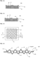
- FIG. 1 to FIG. 3 show a battery buffering member 100, which is an embodiment of the battery buffering member of the present invention.
- the battery buffering member 100 includes an elastic member 20 disposed between two articles in which at least one of the articles expands and contracts, such as battery cells 210 and 210 (see FIG. 17 ), and compressed and deformed under an external force caused by the expansion of the article that expands and contracts, and a heat insulating member 30 that does not receive an external force from the battery cells 210 and 210 and is not compressed and deformed even when the elastic member 20 is compressed and deformed.
- the battery buffering member 100 has an elastic member 20 having protruding portions 22 (a plate-like structure).
- the heat insulating members 30 are plate-like structures having through-holes 31 formed thereon, and the heat insulating member 30 is disposed on one surface 20a side and the other surface 20b side of the elastic member 20, respectively, and the protruding portions 22 of the elastic member 20 protrude from the through-holes 31 of the heat insulating members 30.
- the material of the elastic member 20 is not particularly limited, and examples thereof include rubbers, foamed bodies, and resin-based elastomers.
- the contact area between the battery buffering member and an article such as a battery cell is reduced, and the amount of heat transferred from the contact surface with the article can be reduced. Further, when the protruding portion 22 supports a compressive load caused by the expansion of the article, it is possible to prevent the load from being directly applied to the heat insulating member, and consequently, the heat insulating member can be effectively prevented from being compressed.
- the shape of the protruding portion 22 is not particularly limited, and may be columnar (specifically, cylindrical) as in the protruding portions 22 of the elastic member 20 of the battery buffering member 100 shown in FIG. 1 , and examples thereof include a cylinder, a middle shaft, a spherical shape, a hexagonal pillar shape, a square pillar shape, a triangular prism shape, or a conical shape.
- FIG. 4A shows a protruding portion 22a of a cylinder
- FIG. 4B shows a protruding portion 22b of a middle shaft
- FIG. 4C shows a protruding portion 22c of a spherical shape
- FIG. 4D shows a protruding portion 22d of a hexagonal pillar shape
- FIG. 4E shows a protruding portion 22e of a square pillar shape
- FIG. 4F shows a protruding portion 22f of a triangular prism shape
- FIG. 4G shows a protruding portion 22g of a conical shape.
- the protruding portions 22g of a conical shape may have a protruding shape that tapers toward an apex 24.
- an air layer is formed between the elastic member 20 and an article such as a battery cell, and this air layer further improves the thermal insulation.
- the number and the arrangement state of the protruding portions 22 of the elastic member 20 are not particularly limited, and for example, the same number (four in FIG. 2 ) of protruding parts 22 may be arranged in a plurality of rows (three rows in FIG. 2 ) in parallel as shown in FIG. 2 , or may be arranged as the battery buffering member 101 shown in FIG. 5 . In the battery buffering member 101 shown in FIG. 5 , protruding parts 22 are further arranged between adjacent rows with being shifted.
- the shape of the elastic member 20 is not particularly limited, and for example, the elastic member may have a planar part 21 and protruding portions 22 protruding from the planar part 21 as shown in FIG. 3 .
- the elastic member may have a plate-like part 25 on which an elastic through-hole 23 is formed.
- the elastic member may have a plate-like part 29 on which an elastic recess 27 is formed.
- the elastic member 20 may be a corrugated shape (a corrugated plate shape) with repeated unevenness in a cross section in the thickness direction.
- the heat insulating member 30 does not receive an external force from the above-described articles such as the battery cells 210 and 210 (see FIG. 17 ) and is not compressed and deformed, even when the elastic member 20 is compressed and deformed.
- heat insulating member 30 a conventionally known heat insulating material having heat insulating performance can be used as appropriate, and examples of the material include a fibrous material (glass wool, rock wool, and the like) and a porous material (silica aerogel, and the like).
- a heat insulating member made of such a material is compressed, its heat insulating performance tends to deteriorate.
- the shape of the heat insulating member 30 is not particularly limited, but may be a plate shape in which through-holes 31 are formed, such as the battery buffering members 100 and 106 shown in FIGs. 1 to 3 , 14, and 15 .
- the battery buffering member 103 shown in FIG. 9 it may be a plate shape disposed in the elastic through-hole 23.
- the battery buffering members 104 and 105 shown in FIGs. 12 and 13 it may be a plate shape disposed in the elastic recess 27 of the plate-like part 29.
- a gap that enables compressive deformation of the elastic member that is, a gap that prevents the elastic member (in particular, protruding portions of the elastic member) and the heat insulating member from contacting each other and interfering with each other when the elastic member is compressed and deformed, is formed between the elastic member (in particular, the protruding portions of the elastic member) and the heat insulating member. Since the gap is formed in this manner, a load applied to the heat insulating member 30 can be further avoided when the battery cell or the like expand.
- FIGs. 6 to 8 show a battery buffering member 102 in which a gap 40 that enables compressive deformation of the elastic member 20 is formed between the elastic member 20 and the heat insulating member 30.
- a gap 40 is formed between the heat insulating member 30 and the protruding portion 22 of the elastic member 20, and when the battery buffering member 100 is compressed as shown in FIG. 8 , the protruding portion 22 of the elastic member 20 in particular is deformed to collapse.
- the gap 40 since the gap 40 is formed, it is possible to prevent the heat insulating member 30 from being pressurized by the elastic member 20 (in particular, the protruding portions 22 thereof) even when the battery buffering member 100 is compressed.
- a space is provided between the heat insulating member 30 and elastic member 20 by the deformation amount of the elastic member 20 (the protruding portions 22), and the elastic member 20 is less likely to interfere with the heat insulating member 30 even when the elastic member 20 is deformed.
- FIG. 13 shows a battery buffering member 105 in which a gap 40 that enables compressive deformation of the elastic member 20 is formed between the elastic member 20 and the heat insulating member 30.
- a gap 40 is formed between the heat insulating member 30 and the protruding portion 22 of the elastic member 20. Since the gap 40 is formed, it is possible to prevent the heat insulating member 30 from being pressurized by the elastic member 20 even when the battery buffering member 105 is compressed.
- FIGs. 14 to 16 show a battery buffering member 106 in which a gap 40 that enables compressive deformation of the elastic member 20 is formed between the elastic member 20 and the heat insulating member 30.
- a gap 40 is formed between the heat insulating member 30 and the protruding portions 22g of the elastic member 20, and when the battery buffering member 106 is compressed as shown in FIG. 16 , the protruding portions 22g of the elastic member 20 in particular is deformed to collapse.
- the gap 40 since the gap 40 is formed, it is possible to prevent the heat insulating member 30 from being pressurized by the elastic member 20 (in particular, the protruding portions 22g thereof) even when the battery buffering member 106 is compressed.
- a space is provided between the heat insulating member 30 and the elastic member 20 by the deformation amount of the elastic member 20 (the protruding portions 22g), and the elastic member 20 is less likely to interfere with the heat insulating member 30 even when the elastic member 20 is deformed.
- a battery buffering member 106 shown in FIGs. 14 and 15 can be shown.
- the battery buffering member 106 has an elastic member 20 having protruding portions 22g.
- the heat insulating member 30 is plate-like structure having through-holes 31 formed thereon, the heat insulating member 30 is disposed on one surface 20a side and the other surface 20b side of the elastic member 20, respectively, and the protruding portions 22g of the elastic member 20 protrude from the through-holes 31 of the heat insulating member 30.
- the elastic member 20 has a corrugated shape with repeated unevenness in a cross section in the thickness direction.
- the elastic member and the heat insulating members are preferably separate bodies.
- the elastic member 20 is even less likely to interfere with the heat insulating members 30 even when the elastic member 20 is deformed.
- the battery buffering member of the present invention may be disposed between two articles in which at least one of the articles expands and contracts, and examples of the article may include a battery cell 210 as shown in FIG. 17 , and the battery buffering member may be disposed between adjacent battery cells 210 as in a battery 200 shown in FIG. 17 .
- the battery buffering member may be disposed between a laminated body including the plurality of battery cells 210 and a restraining portion 230 as in a battery 201 shown in FIG. 18 .
- the battery buffering member of the present invention is not limited to one, and a plurality of the buffering members may be used.
- a plurality of the battery buffering members may be laminated to use, or may be disposed on a flat surface to use, or a combination thereof may be used.
- the battery is not limited to an all-solid-state battery, and may be a liquid electrolyte battery.
- the battery buffering member of the present invention absorbs expansion force generated when the battery cell (battery) expands, or functions as a buffering member when the battery receives an impact from an external force.
- the battery buffering member of the present invention can be employed as a battery buffering member such as a lithium battery used in an electric vehicle or the like.
Landscapes
- Chemical & Material Sciences (AREA)
- Chemical Kinetics & Catalysis (AREA)
- Electrochemistry (AREA)
- General Chemical & Material Sciences (AREA)
- Engineering & Computer Science (AREA)
- Manufacturing & Machinery (AREA)
- Battery Mounting, Suspending (AREA)
- Secondary Cells (AREA)
Applications Claiming Priority (2)
| Application Number | Priority Date | Filing Date | Title |
|---|---|---|---|
| JP2022090743 | 2022-06-03 | ||
| PCT/JP2023/016308 WO2023233874A1 (ja) | 2022-06-03 | 2023-04-25 | バッテリー用緩衝材 |
Publications (1)
| Publication Number | Publication Date |
|---|---|
| EP4535517A1 true EP4535517A1 (en) | 2025-04-09 |
Family
ID=89026261
Family Applications (1)
| Application Number | Title | Priority Date | Filing Date |
|---|---|---|---|
| EP23815635.0A Pending EP4535517A1 (en) | 2022-06-03 | 2023-04-25 | Buffering material for batteries |
Country Status (6)
| Country | Link |
|---|---|
| US (1) | US20250105428A1 (https=) |
| EP (1) | EP4535517A1 (https=) |
| JP (2) | JP7591694B2 (https=) |
| KR (1) | KR20250006969A (https=) |
| CN (1) | CN119156731A (https=) |
| WO (1) | WO2023233874A1 (https=) |
Families Citing this family (1)
| Publication number | Priority date | Publication date | Assignee | Title |
|---|---|---|---|---|
| JP2025105240A (ja) * | 2023-12-28 | 2025-07-10 | ソフトバンク株式会社 | 拘束具、電池システム、及び飛行体 |
Family Cites Families (4)
| Publication number | Priority date | Publication date | Assignee | Title |
|---|---|---|---|---|
| JP5036971B2 (ja) * | 2004-10-08 | 2012-09-26 | 本田技研工業株式会社 | バッテリボックス構造 |
| CN113906615B (zh) * | 2019-06-28 | 2024-04-23 | 三洋电机株式会社 | 电源装置和具有该电源装置的电动车辆以及蓄电装置 |
| JP7441643B2 (ja) * | 2019-12-23 | 2024-03-01 | 信越ポリマー株式会社 | セルユニット、それを備えるバッテリー、およびバッテリーの製造方法 |
| JP7292231B2 (ja) | 2020-03-06 | 2023-06-16 | ニチアス株式会社 | 電池用断熱材及び電池 |
-
2023
- 2023-04-25 JP JP2024524243A patent/JP7591694B2/ja active Active
- 2023-04-25 US US18/852,890 patent/US20250105428A1/en active Pending
- 2023-04-25 KR KR1020247039645A patent/KR20250006969A/ko active Pending
- 2023-04-25 EP EP23815635.0A patent/EP4535517A1/en active Pending
- 2023-04-25 CN CN202380038654.0A patent/CN119156731A/zh active Pending
- 2023-04-25 WO PCT/JP2023/016308 patent/WO2023233874A1/ja not_active Ceased
-
2024
- 2024-11-18 JP JP2024200660A patent/JP2025026933A/ja active Pending
Also Published As
| Publication number | Publication date |
|---|---|
| KR20250006969A (ko) | 2025-01-13 |
| US20250105428A1 (en) | 2025-03-27 |
| CN119156731A (zh) | 2024-12-17 |
| WO2023233874A1 (ja) | 2023-12-07 |
| JP7591694B2 (ja) | 2024-11-28 |
| JP2025026933A (ja) | 2025-02-26 |
| JPWO2023233874A1 (https=) | 2023-12-07 |
Similar Documents
| Publication | Publication Date | Title |
|---|---|---|
| JP7174923B2 (ja) | 蓄電装置 | |
| US9214658B2 (en) | Battery pack | |
| JP2020004556A (ja) | 電池モジュール用緩衝シート | |
| US11870089B2 (en) | Battery cell pack | |
| US12261313B2 (en) | Buffer member and power storage module | |
| US11139540B2 (en) | Battery module and battery pack | |
| JP5521442B2 (ja) | 組電池 | |
| CN113924687A (zh) | 缓冲构件、蓄电模块以及缓冲构件的制造方法 | |
| CN209217069U (zh) | 二次电池以及电池模组 | |
| EP4535517A1 (en) | Buffering material for batteries | |
| WO2020110448A1 (ja) | 電池モジュール | |
| JP6463471B2 (ja) | バッテリーケース、バッテリーモジュールおよびバッテリーモジュールの製造方法 | |
| US11563254B2 (en) | Battery module and battery pack | |
| JP6031388B2 (ja) | 組電池 | |
| KR102935055B1 (ko) | 조전지 | |
| US20250329842A1 (en) | Battery buffering material | |
| WO2020059299A1 (ja) | 電池モジュール | |
| US11177542B2 (en) | Secondary battery and battery module | |
| JP2022075152A (ja) | リチウムイオン電池 | |
| JP6380080B2 (ja) | 電池モジュール | |
| US20250192261A1 (en) | Battery module | |
| JP7680927B2 (ja) | セル積層体、及びバッテリモジュール | |
| EP4498480A2 (en) | Battery assembly | |
| KR20250149897A (ko) | 개선된 엔드 스페이서를 갖는 전지 시스템과 이를 포함하는 차량 | |
| JP2026068619A (ja) | 蓄電装置 |
Legal Events
| Date | Code | Title | Description |
|---|---|---|---|
| STAA | Information on the status of an ep patent application or granted ep patent |
Free format text: STATUS: THE INTERNATIONAL PUBLICATION HAS BEEN MADE |
|
| PUAI | Public reference made under article 153(3) epc to a published international application that has entered the european phase |
Free format text: ORIGINAL CODE: 0009012 |
|
| STAA | Information on the status of an ep patent application or granted ep patent |
Free format text: STATUS: REQUEST FOR EXAMINATION WAS MADE |
|
| 17P | Request for examination filed |
Effective date: 20240927 |
|
| AK | Designated contracting states |
Kind code of ref document: A1 Designated state(s): AL AT BE BG CH CY CZ DE DK EE ES FI FR GB GR HR HU IE IS IT LI LT LU LV MC ME MK MT NL NO PL PT RO RS SE SI SK SM TR |
|
| DAV | Request for validation of the european patent (deleted) | ||
| DAX | Request for extension of the european patent (deleted) |