EP4535506A1 - Battery pack for preventing overheating misdiagnosis due to environmental temperature and method for preventing misdiagnosis - Google Patents
Battery pack for preventing overheating misdiagnosis due to environmental temperature and method for preventing misdiagnosis Download PDFInfo
- Publication number
- EP4535506A1 EP4535506A1 EP24819446.6A EP24819446A EP4535506A1 EP 4535506 A1 EP4535506 A1 EP 4535506A1 EP 24819446 A EP24819446 A EP 24819446A EP 4535506 A1 EP4535506 A1 EP 4535506A1
- Authority
- EP
- European Patent Office
- Prior art keywords
- battery pack
- pack
- temperature
- overheating
- battery
- Prior art date
- Legal status (The legal status is an assumption and is not a legal conclusion. Google has not performed a legal analysis and makes no representation as to the accuracy of the status listed.)
- Pending
Links
Images




Classifications
-
- H—ELECTRICITY
- H01—ELECTRIC ELEMENTS
- H01M—PROCESSES OR MEANS, e.g. BATTERIES, FOR THE DIRECT CONVERSION OF CHEMICAL ENERGY INTO ELECTRICAL ENERGY
- H01M10/00—Secondary cells; Manufacture thereof
- H01M10/42—Methods or arrangements for servicing or maintenance of secondary cells or secondary half-cells
- H01M10/48—Accumulators combined with arrangements for measuring, testing or indicating the condition of cells, e.g. the level or density of the electrolyte
- H01M10/486—Accumulators combined with arrangements for measuring, testing or indicating the condition of cells, e.g. the level or density of the electrolyte for measuring temperature
-
- H—ELECTRICITY
- H01—ELECTRIC ELEMENTS
- H01M—PROCESSES OR MEANS, e.g. BATTERIES, FOR THE DIRECT CONVERSION OF CHEMICAL ENERGY INTO ELECTRICAL ENERGY
- H01M10/00—Secondary cells; Manufacture thereof
- H01M10/42—Methods or arrangements for servicing or maintenance of secondary cells or secondary half-cells
- H01M10/425—Structural combination with electronic components, e.g. electronic circuits integrated to the outside of the casing
-
- H—ELECTRICITY
- H01—ELECTRIC ELEMENTS
- H01M—PROCESSES OR MEANS, e.g. BATTERIES, FOR THE DIRECT CONVERSION OF CHEMICAL ENERGY INTO ELECTRICAL ENERGY
- H01M10/00—Secondary cells; Manufacture thereof
- H01M10/42—Methods or arrangements for servicing or maintenance of secondary cells or secondary half-cells
- H01M10/48—Accumulators combined with arrangements for measuring, testing or indicating the condition of cells, e.g. the level or density of the electrolyte
- H01M10/482—Accumulators combined with arrangements for measuring, testing or indicating the condition of cells, e.g. the level or density of the electrolyte for several batteries or cells simultaneously or sequentially
-
- H—ELECTRICITY
- H01—ELECTRIC ELEMENTS
- H01M—PROCESSES OR MEANS, e.g. BATTERIES, FOR THE DIRECT CONVERSION OF CHEMICAL ENERGY INTO ELECTRICAL ENERGY
- H01M50/00—Constructional details or processes of manufacture of the non-active parts of electrochemical cells other than fuel cells, e.g. hybrid cells
- H01M50/20—Mountings; Secondary casings or frames; Racks, modules or packs; Suspension devices; Shock absorbers; Transport or carrying devices; Holders
- H01M50/204—Racks, modules or packs for multiple batteries or multiple cells
-
- H—ELECTRICITY
- H01—ELECTRIC ELEMENTS
- H01M—PROCESSES OR MEANS, e.g. BATTERIES, FOR THE DIRECT CONVERSION OF CHEMICAL ENERGY INTO ELECTRICAL ENERGY
- H01M10/00—Secondary cells; Manufacture thereof
- H01M10/42—Methods or arrangements for servicing or maintenance of secondary cells or secondary half-cells
- H01M10/425—Structural combination with electronic components, e.g. electronic circuits integrated to the outside of the casing
- H01M2010/4271—Battery management systems including electronic circuits, e.g. control of current or voltage to keep battery in healthy state, cell balancing
-
- H—ELECTRICITY
- H01—ELECTRIC ELEMENTS
- H01M—PROCESSES OR MEANS, e.g. BATTERIES, FOR THE DIRECT CONVERSION OF CHEMICAL ENERGY INTO ELECTRICAL ENERGY
- H01M50/00—Constructional details or processes of manufacture of the non-active parts of electrochemical cells other than fuel cells, e.g. hybrid cells
- H01M50/20—Mountings; Secondary casings or frames; Racks, modules or packs; Suspension devices; Shock absorbers; Transport or carrying devices; Holders
- H01M50/204—Racks, modules or packs for multiple batteries or multiple cells
- H01M50/207—Racks, modules or packs for multiple batteries or multiple cells characterised by their shape
- H01M50/209—Racks, modules or packs for multiple batteries or multiple cells characterised by their shape adapted for prismatic or rectangular cells
-
- Y—GENERAL TAGGING OF NEW TECHNOLOGICAL DEVELOPMENTS; GENERAL TAGGING OF CROSS-SECTIONAL TECHNOLOGIES SPANNING OVER SEVERAL SECTIONS OF THE IPC; TECHNICAL SUBJECTS COVERED BY FORMER USPC CROSS-REFERENCE ART COLLECTIONS [XRACs] AND DIGESTS
- Y02—TECHNOLOGIES OR APPLICATIONS FOR MITIGATION OR ADAPTATION AGAINST CLIMATE CHANGE
- Y02E—REDUCTION OF GREENHOUSE GAS [GHG] EMISSIONS, RELATED TO ENERGY GENERATION, TRANSMISSION OR DISTRIBUTION
- Y02E60/00—Enabling technologies; Technologies with a potential or indirect contribution to GHG emissions mitigation
- Y02E60/10—Energy storage using batteries
Definitions
- the present invention relates to a technology for detecting battery overheating.
- the present invention relates to a battery pack and a detection method for detecting causes of battery overheating by distinguishing an increase in temperature of a battery itself and an increase in temperature due to external environmental factors.
- Overheating often occurs due to an increase in temperature of a battery during a battery operation. In this case, it is often difficult to determine whether the cause is due to the increase in temperature of the battery itself or the increase in temperature of the external environments.
- thermo sensors are installed around the battery cell and on a surface of the battery cell, respectively to detect an increase in ambient temperature by using a difference between the temperature of the battery cell itself and the temperature around the battery cell even before the temperature of the battery cell rises, thereby quickly diagnosing an abnormal condition in temperature of the battery cell.
- none of the above prior arts provides a technology for diagnosing battery overheating by distinguishing whether it is due to overheating of the cells or an increase in temperature of the external environment.
- the present invention provides a method for diagnosing whether overheating is due to an increase in temperature of a battery pack, due to an increase in temperature of battery cells, or due to an increase in external temperature, which is not provided by the above-described related art, and a battery pack that enables the diagnosis method.
- BMS battery management system
- the BMS may be configured to receive the measured values from the cell temperature sensor at a predetermined period so as to determine the increase in internal temperature of the battery pack and receive the measured values from the pack temperature sensor at a predetermined period so as to determine the increase in external temperature of the battery pack and may be configured to receive the measured values from the cell temperature sensor and the pack temperature sensor so as to calculate a pack internal temperature and a pack external temperature from the measured values and perform the overheating diagnosis of the battery pack based on the pack internal temperature and pack external temperature values, wherein if the external temperature value of the pack increases faster than the internal temperature value of the pack so that the overheating is diagnosed, the cause of the overheating diagnosis may be determined to be caused by external factors to the battery pack.
- the battery pack according to the present invention may further include a BMS temperature sensor disposed adjacent to the BMS, wherein the BMS may be configured to receive measured values from the cell temperature sensor and the BMS temperature sensor at a predetermined period so as to determine the increase in internal temperature of the battery pack.
- the pack temperature sensor according to the present invention may be mounted on an inner surface or an outer surface of the pack case, and when the pack temperature sensor is mounted on the outer surface, the pack case may be provided with a temperature measurement hole at a position corresponding to a portion at which the pack temperature sensor is attached, and a heat dissipation film may be attached to a top surface of the pack temperature sensor facing the inner surface of the pack case to block heat.
- the present invention provides a system for diagnosing overheating of a battery pack, the system including: the one or more battery packs; and an upper level controller configured to receive the internal temperature of the battery pack and the external temperature of the battery pack from the battery pack so as to perform the overheating diagnosis of the battery pack.
- the upper level controller may be configured to determine that the overheating is caused by external factors of the pack when the external temperature of the battery pack increases above a predetermined reference value earlier than the internal temperature of the battery pack.
- the present invention provides a method for diagnosing overheating of a battery pack, the method including: a battery pack internal temperature measurement process of measuring an internal temperature of the battery pack at a predetermined period; a battery pack external temperature measurement process of measuring an external temperature of the battery pack at a predetermined period; a battery pack overheating diagnosis process of diagnosing whether the battery pack is overheated based on the pack internal temperature and the pack external temperature; and an overheating diagnosis cause determination process of determining that the overheating diagnosis is misdiagnosed when the external temperature of the pack increases faster than the internal temperature of the pack in the overheating diagnosis process.
- the overheating diagnosis process when the internal temperature of the pack is greater than the predetermined reference value, the overheating may be diagnosed as the overheating of the battery pack
- the overheating diagnosis cause determination process when the external temperature of the pack increases faster than the internal temperature of the pack, the overheating may be diagnosed as the overheating due to the increase in external temperature.
- the pack internal temperature may be acquired from a battery cell accommodated inside a pack case of the battery pack or a temperature sensor mounted on a BMS, and the pack external temperature may be obtained from a temperature sensor attached to the pack case of the battery pack.
- the present invention provides a method for diagnosing overheating of a battery system, comprising: a battery pack temperature measurement process in which each battery pack measures the internal temperature and the external temperature of each battery pack; a measurement value reception process in which the upper level controller receives measured values of the internal and external temperatures of each battery pack; an overheating diagnosis process in which the upper level controller performs the overheating diagnosis of each battery pack based on the received measured values of the internal and external temperatures of each battery pack; and an overheating diagnosis cause determination process of determining whether the overheating diagnosis is due to internal or external factors of the battery pack.
- each battery pack measures the internal temperature and external temperature from different temperature sensors attached to different positions of the battery pack, the internal temperature is acquired from a battery cell accommodated inside a pack case of the battery pack or a temperature sensor mounted on a BMS, and the external temperature is acquired from a temperature sensor attached to the pack case of the battery pack.
- the internal temperature and the external temperature of the battery pack may be measured at the predetermined period from the different temperature sensors installed in each of the battery cells, the BMS, and the pack case of the battery pack and then be compared with the predetermined reference value to perform the battery pack overheating diagnosis, in particular, determine whether the causes of the overheating are due to the internal or external factors of the battery pack, thereby preventing the misdiagnosis of the overheating or investigating the cause of the overheating so as to improve the efficiency of battery operation.
- the battery pack 100 may include a plurality of battery cells 10, a battery management system (BMS) 20 that manages the battery cells, a battery pack case 30 that accommodates the plurality of battery cells and the BMS, one or more cell temperature sensors 40 that measure temperatures of the battery cells, and one or more pack temperature sensors 60 that measure a temperature of the battery pack, and may further include one or more BMS temperature sensors 50 that measure a temperature of the BMS.
- BMS battery management system
- the battery pack 100 includes typical battery cells 10.
- One or more cell temperature sensors 40 that measure temperature of the cells are mounted on the battery cells 10.
- the cell temperature sensors 40 may be attached to the battery cells through a FPCB 70 for mounting the temperature sensor.
- FIG. 2a is a side cross-sectional view illustrating a state in which two cell temperature sensors 40 are mounted at different positions of the battery cell 10 by using the FPCB 70 for mounting the temperature sensor
- FIG. 2b is a top view illustrating a state in which the cell temperature sensor 40 is mounted.
- the battery pack 100 includes a typical BMS 20.
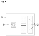
- a BMS temperature sensor 50 that measures a temperature around the BMS 20 is mounted on a board constituting the BMS 20. As illustrated in the block diagram of FIG. 3 , the BMS temperature sensor 50 may be disposed around other elements 21 constituting the BMS 20, and a detailed circuit pattern such as a connection relationship between the elements was omitted in the block diagram of FIG. 3 .
- the BMS 20 according to the present invention adopts a typical BMS in its structure, but its function performs a method for diagnosing a temperature of the battery pack according to the present invention.
- the BMS 20 reads temperature measurement signals from the cell temperature sensor 40, the pack temperature sensors 60, or the additional BMS temperature sensor 50 at positions at which the respective sensors are mounted to calculate temperatures of the cell, the BMS, and the pack case based on the read temperature measurement signals.
- the pack case temperature calculated from the measured value of the pack temperature sensor 60 calculates an environmental temperature outside the battery pack 100.
- the BMS 20 performs the overheating diagnosis of the battery pack using the cell temperature and pack case temperature, or additionally the BMS ambient temperature.
- the overheating is diagnosed, it is determined whether the cause of the overheating diagnosis is due to an increase in temperature of the internal battery cell or the BMS or due to an increase in external environmental temperature of the battery pack 100. Specific procedure and method for determining whether the cause of the overheating diagnosis is due to the increase in temperature inside the battery pack or increase in temperature outside the battery pack are described below.
- the pack case 30 accommodates the plurality of battery cells 10 and the BMS 20 and includes one or more pack temperature sensors 60.
- the pack temperature sensors 60 may be attached to an outer surface of the pack case 30 as illustrated in FIG. 4a or an inner surface of the pack case 30 as illustrated in FIG. 4b . When attached to the inner or outer surface, the pack temperature sensors 60 may be mounted and attached to the sensor-mounted FPCB 70 as illustrated in FIG. 4 .
- the pack case 30 may include a temperature measurement hole 31.
- the temperature measurement hole 31 is defined to correspond to the attachment position of the pack temperature sensor 60, especially when the pack temperature sensor 60 is installed on the inner surface of the pack case 30, and thus, the pack temperature sensor 60 is affected more by the external temperature than the internal temperature of the pack case 30 so that the pack temperature sensor 60 is configured to be more sensitive to the external environmental temperature.
- a top surface of the sensor-mounted FPCB 70 facing the inner surface of the pack case 30 of the pack temperature sensor 60, that is, a top surface of the pack temperature sensor may be provided with a heat dissipation film to dissipate heat so that the pack temperature sensor 60 is configured to be less sensitive to the internal temperature of the pack case 30.
- FIGS. 4c and 4d illustrate a configuration in which a temperature transfer pin 32 is disposed in the temperature measuring hole 31 for sealing purposes such as waterproofing or for transferring the external temperature.
- One end of the temperature transfer pin 32 is in contact with the pack temperature sensor 60 attached to the inner surface of the pack case, and the other end of the temperature transfer pin 32 is exposed to the outside of the pack case 30 through the temperature measurement hole 31 to transfer the external temperature to the pack temperature sensor 60.
- FIG. 4d it is shown as if there is a pore in the temperature measurement hole 31 and the temperature transfer pin 32, but this is shown for identification on the drawing, and in reality, for case sealing, the pore between the temperature transfer pin 32 and an inner circumferential surface of the temperature measuring hole 31 may be filled with the same material as the temperature transfer pin 32, the same material as the pack case 30, or a heat transfer material.
- the temperature transfer pin 32 may be made of a known heat transfer material for the purpose of better transferring the temperature outside the pack case 30 to the pack temperature sensor 60.
- the pack temperature sensor 60 may be mounted on the FPCB 31 (flexible printed circuit board) with a printed wire for signal connection to the BMS 20, and the FPCB may be attached to the inner surface or outer surface of the pack case 30 so that the pack temperature sensor 60 measures the temperature of the pack case 30.
- FPCB 31 flexible printed circuit board
- the FPCB may be attached to the inner surface or outer surface of the pack case 30 so that the pack temperature sensor 60 measures the temperature of the pack case 30.
- the cell temperature sensor 40 is provided on a surface of the battery cell 10 to measure a cell surface temperature at predetermined periodic intervals and is connected to transmit a signal for calculating the measured temperature to the BMS.
- the cell temperature sensor 40 may be attached to each surface of the plurality of battery cells 10 to calculate the temperature of each of the plurality of battery cells 10, and as illustrated in FIG. 2 , the individual battery cells 10 may be attached to a plurality of positions, respectively.
- the BMS temperature sensor 50 is installed on the BMS 20 to measure an ambient temperature. As illustrated in FIG. 3 , the BMS temperature sensor 50 is installed on a printed circuit board (PCB) constituting the BMS 20 to measure a temperature around the BMS 20.
- PCB printed circuit board
- the installed position of the BMS temperature sensor 50 according to the present invention is not limited to the PCB of the BMS and may be configured to be mounted on the sensor-mounted FPCB 70 and attached around the BMS 20.
- one or more pack temperature sensors 60 are attached to the inner or outer surface of the pack case 30 to measure a temperature outside the battery pack case 30 rather than the battery cell 10 or the BMS 20, thereby transmitting a measured value to the BMS 20.
- an attachment type of cell temperature sensors to pack temperature sensors is not limited to a specific one.
- the attachment type it may be attached to the inner or outer surface of the battery cell 10, the BMS 20, or the pack case 30 through the sensor-mounted FPCB 70 as illustrated in FIG. 5 .
- a specific circuit pattern is omitted.
- the sensor-mounted FPCB 70 forms a sensor mounting part 73 on which the temperature sensors are mounted.
- the temperature sensors are attached to the sensor mounting part 73 to form a temperature measurement portion, and a temperature sensor connection wire 71 of the sensor-mounted FPCB 70 is connected to wire patterns of the FPCB 70, to which the temperature sensors 40, 50, and 60 are connected to transmit the measured values from the sensors to the BMS 20, to transmit the measured values of the temperature sensors to the BMS.
- the sensor-mounted FPCB 70 on which the pack temperature sensor 60 is mounted is attached to the outer surface of the pack case 30, the sensor-mounted FPCB 70 is connected inside the pack case 30 to transmit the measured value of the pack temperature sensor 60 to the BMS.
- a wire connection hole (not shown) for internal connection of the temperature sensor connection wire 71 may be defined in the pack case 30.
- the battery pack 100 measures the temperatures inside and outside the battery pack by including the cell temperature sensor or the pack temperature sensor, and when diagnosing the overheating of each battery pack 100, the BMS 20 of each battery pack 100 uses the measured value of the cell temperature sensor or the pack temperature sensor to determine whether the cause of the overheating diagnosis is due to an increase in internal temperature of the battery pack 100 or an increase in external temperature and then transmit the determined result to the upper level controller 210.
- the upper level controller 210 may be a battery rack constituted by the plurality of battery packs 100 or a controller of a system constituted by the plurality of battery packs 100 and the plurality of battery racks.
- the BMS 20 of the battery pack 100 transmits the temperature measurement value to the upper level controller 210, and the upper level controller 210 receives the temperature measurement results from each battery pack 100 to perform the overheating diagnosis of each battery pack 100 and determine whether the cause of the overheating diagnosis is due to the increase in temperature inside the battery pack or the increase in temperature outside the battery pack.
- This process is a procedure in which a BMS 20 measures a temperature of a battery cell 10 at predetermined periodic intervals from at least one or more cell temperature sensors 40 attached to the battery cell 10.
- the battery internal temperature measurement process may include a procedure in which the BMS 20 additionally measures a BMS temperature from a BMS temperature sensor 50 attached around the BMS 20 in addition to the cell temperature sensors 40.
- the BMS 20 may calculate a maximum value of the measured temperatures of the battery cells 10 and the BMS as a battery internal temperature to determine the overheating by comparing the maximum value with a predetermined first reference value.
- This process is a procedure in which the BMS 20 determines an external temperature of the battery pack using the measured values from at least one or more pack temperature sensors 60 attached to the battery pack case 30 of the battery pack 100.
- the BMS 20 may determine the overheating by comparing the external temperature of the battery pack with a predetermined second reference value.
- This process is a procedure in which the BMS 20 diagnoses the overheating of the battery pack by comparing the internal temperature of the battery pack and the external temperature of the battery pack measured in operations S10 and S20 with a predetermined reference value.
- the battery pack overheating diagnosis process if the internal temperature of the battery pack is higher than the predetermined first reference value, or the external temperature of the battery pack is higher than the predetermined second reference value, it is diagnosed as the overheating.
- the first reference value and the second reference value may be set to be the same or may be set to be different from each other.
- the internal temperature of the battery pack when the internal temperature of the battery pack is not higher than the predetermined first reference value even if the external temperature of the battery pack is higher than the second reference value, in a predetermined temperature measurement cycle, it may not be diagnosed as the overheating, and only when the battery pack internal temperature is higher than the predetermined first reference value, it may be diagnosed as the overheating.
- the BMS 20 performs the operations S10 to S30 at predetermined periodic intervals, and when the battery pack overheating is diagnosed in the operation S30 of the predetermined period, it is determined whether the overheating is diagnosed due to an increase in internal temperature of the battery pack or an increase in external temperature of the battery pack.
- the battery pack overheating diagnosis is caused by the external factors of the battery pack, or that the overheating diagnosis is misdiagnosed.
- the battery pack overheating diagnosis process (S30), when the internal temperature of the battery pack is not higher than the predetermined first reference value even if the external temperature of the battery pack is higher than the second reference value, in a predetermined temperature measurement cycle, it may not be diagnosed as the overheating, and only when the battery pack internal temperature is higher than the predetermined first reference value, it may be diagnosed as the overheating.
- the BMS 20 determines that the external temperature of the battery pack increases earlier than the predetermined second reference value when the internal temperature of the battery pack is higher than the predetermined first reference value, and then, determines that the cause of the overheating diagnosis is due to the external factors of the battery pack if the internal temperature of the battery pack is higher than the predetermined first reference value.
- the method in which the upper level controller 210 performs the overheating diagnosis of each battery pack is the same.
- the upper level controller 210 performs the overheating diagnosis for each battery pack and determines the cause of the overheating.
- the present invention provides a method for diagnosing overheating of a battery system including one or more battery packs provided with separate temperature sensors to measure each of internal and external temperatures of a battery pack, and an upper level controller that receives the internal and external temperatures of each battery pack from the battery pack, and the method includes: a battery pack temperature measurement process in which each battery pack measures the internal temperature and the external temperature of each battery pack; a measurement value reception process in which the upper level controller receives measured values of the internal and external temperatures of each battery pack; an overheating diagnosis process in which the upper level controller performs the overheating diagnosis of each battery pack based on the received internal and external temperature measurements of each battery pack; and an overheating diagnosis cause determination process of determining whether the overheating diagnosis is due to internal or external factors of the battery pack.
- each battery pack measures the internal temperature and external temperature from different temperature sensors attached to different positions of the battery pack, the internal temperature is acquired from a battery cell accommodated inside a pack case of the battery pack or a temperature sensor mounted on a BMS, and the external temperature is acquired from a temperature sensor attached to the pack case of the battery pack.
- the respective temperature sensors correspond to the cell temperature sensor 40, the BMS temperature sensor 50, and the pack temperature sensor 60, which are described above.
- the overheating diagnosis or the overheating diagnosis cause determination of each battery pack according to the present invention described above may be well understood by those skilled in the art that the overheating diagnosis method is performed by mounting a series of processor execution algorithms that perform the operations S10 to S40 in the BMS 20 or the upper level controller 210 of each battery pack.
- the battery pack and the method for diagnosing the overheating of the battery pack according to the present invention when diagnosing the overheating for a stable operation of the battery, whether the overheating is diagnosed due to the overheating of the battery cells constituting the battery pack or the BMS itself, or overheating is diagnosed due to the environmental factors outside the battery pack may be distinguished to achieve the more accurate battery operation.
- the reference numerals and names of each component used are as follows. 100 Battery pack 200 System for diagnosing overheating of battery pack 10 Battery pack 20 BMS 30 Pack case 31 Temperature measurement hole 32 Temperature transfer pin 40 Cell temperature sensor 50 BMS temperature sensor 60 Pack temperature sensor 70 sensor-mounted FPCB 71 Temperature sensor connection wire 72 Heat dissipation film 73 Sensor mounting part 210 Upper level controller
Landscapes
- Engineering & Computer Science (AREA)
- Chemical & Material Sciences (AREA)
- Chemical Kinetics & Catalysis (AREA)
- Electrochemistry (AREA)
- General Chemical & Material Sciences (AREA)
- Manufacturing & Machinery (AREA)
- Microelectronics & Electronic Packaging (AREA)
- Secondary Cells (AREA)
- Battery Mounting, Suspending (AREA)
- Testing Electric Properties And Detecting Electric Faults (AREA)
Abstract
Description
- The present invention relates to a technology for detecting battery overheating. In particular, the present invention relates to a battery pack and a detection method for detecting causes of battery overheating by distinguishing an increase in temperature of a battery itself and an increase in temperature due to external environmental factors.
- Overheating often occurs due to an increase in temperature of a battery during a battery operation. In this case, it is often difficult to determine whether the cause is due to the increase in temperature of the battery itself or the increase in temperature of the external environments.
- In this regard, in a case such as Patent Document 1, in order to solve the problem of determining temperature abnormality based on only an absolute temperature of the battery cell itself, without reflecting any change in ambient temperature of the battery cell, temperature sensors are installed around the battery cell and on a surface of the battery cell, respectively to detect an increase in ambient temperature by using a difference between the temperature of the battery cell itself and the temperature around the battery cell even before the temperature of the battery cell rises, thereby quickly diagnosing an abnormal condition in temperature of the battery cell.
- In case of Patent Document 2, a technology in which a pack temperature of a pack case is measured to equalize temperatures of battery cells, and only when the pack temperature is below an appropriate temperature range, the cells of which cell temperatures are below an average cell temperature are heated to balance the pack temperature to the appropriate temperature range is disclosed.
- However, none of the above prior arts provides a technology for diagnosing battery overheating by distinguishing whether it is due to overheating of the cells or an increase in temperature of the external environment.
- The present invention provides a method for diagnosing whether overheating is due to an increase in temperature of a battery pack, due to an increase in temperature of battery cells, or due to an increase in external temperature, which is not provided by the above-described related art, and a battery pack that enables the diagnosis method.
- To solve the above problems, a battery pack configured to perform overheating diagnosis of a battery pack includes: one or more battery cells; a battery management system (BMS) configured to diagnose overheating of the battery pack according to an increase in internal temperature of the battery pack or an increase in external temperature of the battery pack and determine whether a cause of the overheating diagnosis is due to an increase in internal temperature of the battery pack or an increase in external temperature; a pack case configured to accommodate the battery cells and the BMS; one or more cell temperature sensors disposed adjacent to the battery cells and configured to provide measured values for determining the increase in internal temperature of the battery pack; and one or more pack temperature sensors attached to an inner or outer surface of the pack case and configured to provide the measured values for determining the increase in external temperature of the battery pack.
- Here, the BMS may be configured to receive the measured values from the cell temperature sensor at a predetermined period so as to determine the increase in internal temperature of the battery pack and receive the measured values from the pack temperature sensor at a predetermined period so as to determine the increase in external temperature of the battery pack and may be configured to receive the measured values from the cell temperature sensor and the pack temperature sensor so as to calculate a pack internal temperature and a pack external temperature from the measured values and perform the overheating diagnosis of the battery pack based on the pack internal temperature and pack external temperature values, wherein if the external temperature value of the pack increases faster than the internal temperature value of the pack so that the overheating is diagnosed, the cause of the overheating diagnosis may be determined to be caused by external factors to the battery pack.
- In addition, the battery pack according to the present invention may further include a BMS temperature sensor disposed adjacent to the BMS, wherein the BMS may be configured to receive measured values from the cell temperature sensor and the BMS temperature sensor at a predetermined period so as to determine the increase in internal temperature of the battery pack. The pack temperature sensor according to the present invention may be mounted on an inner surface or an outer surface of the pack case, and when the pack temperature sensor is mounted on the outer surface, the pack case may be provided with a temperature measurement hole at a position corresponding to a portion at which the pack temperature sensor is attached, and a heat dissipation film may be attached to a top surface of the pack temperature sensor facing the inner surface of the pack case to block heat.
- In addition, the present invention provides a system for diagnosing overheating of a battery pack, the system including: the one or more battery packs; and an upper level controller configured to receive the internal temperature of the battery pack and the external temperature of the battery pack from the battery pack so as to perform the overheating diagnosis of the battery pack. When diagnosing the overheating of the battery pack, the upper level controller may be configured to determine that the overheating is caused by external factors of the pack when the external temperature of the battery pack increases above a predetermined reference value earlier than the internal temperature of the battery pack.
- In addition, the present invention provides a method for diagnosing overheating of a battery pack, the method including: a battery pack internal temperature measurement process of measuring an internal temperature of the battery pack at a predetermined period; a battery pack external temperature measurement process of measuring an external temperature of the battery pack at a predetermined period; a battery pack overheating diagnosis process of diagnosing whether the battery pack is overheated based on the pack internal temperature and the pack external temperature; and an overheating diagnosis cause determination process of determining that the overheating diagnosis is misdiagnosed when the external temperature of the pack increases faster than the internal temperature of the pack in the overheating diagnosis process.
- Here, in the overheating diagnosis process, when the internal temperature of the pack is greater than the predetermined reference value, the overheating may be diagnosed as the overheating of the battery pack, in the overheating diagnosis cause determination process, when the external temperature of the pack increases faster than the internal temperature of the pack, the overheating may be diagnosed as the overheating due to the increase in external temperature. Here, the pack internal temperature may be acquired from a battery cell accommodated inside a pack case of the battery pack or a temperature sensor mounted on a BMS, and the pack external temperature may be obtained from a temperature sensor attached to the pack case of the battery pack.
- Furthermore, the present invention provides a method for diagnosing overheating of a battery system, comprising: a battery pack temperature measurement process in which each battery pack measures the internal temperature and the external temperature of each battery pack; a measurement value reception process in which the upper level controller receives measured values of the internal and external temperatures of each battery pack; an overheating diagnosis process in which the upper level controller performs the overheating diagnosis of each battery pack based on the received measured values of the internal and external temperatures of each battery pack; and an overheating diagnosis cause determination process of determining whether the overheating diagnosis is due to internal or external factors of the battery pack.
- Here, each battery pack measures the internal temperature and external temperature from different temperature sensors attached to different positions of the battery pack, the internal temperature is acquired from a battery cell accommodated inside a pack case of the battery pack or a temperature sensor mounted on a BMS, and the external temperature is acquired from a temperature sensor attached to the pack case of the battery pack.
- According to the present invention, the internal temperature and the external temperature of the battery pack may be measured at the predetermined period from the different temperature sensors installed in each of the battery cells, the BMS, and the pack case of the battery pack and then be compared with the predetermined reference value to perform the battery pack overheating diagnosis, in particular, determine whether the causes of the overheating are due to the internal or external factors of the battery pack, thereby preventing the misdiagnosis of the overheating or investigating the cause of the overheating so as to improve the efficiency of battery operation.
- The following drawings attached in this specification illustrate a preferred embodiment of the present invention and function to make further understood the technical spirit of the present invention along with the detailed description of the invention. The present invention should not be construed as being limited to only the drawings.
-
FIG. 1 is a view illustrating a structure of a battery pack according to an embodiment of the present invention. -
FIG. 2 is a view illustrating a structure in which a cell temperature sensor is mounted on a battery cell according to an embodiment of the present invention. -
FIG. 3 is a view illustrating a structure in which a BMS temperature sensor is mounted on a BMS according to an embodiment of the present invention. -
FIG. 4 is a view illustrating a structure of a pack case and a structure in which a pack temperature sensor is mounted on a pack case according to an embodiment of the present invention. -
FIG. 5 is a view illustrating a structure of a FPCB including a temperature sensor according to an embodiment of the present invention. -
FIG. 6 is a block diagram illustrating a configuration of a system in which a plurality of battery packs are controlled by an upper level controller according to the present invention. -
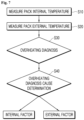
FIG. 7 is a flowchart illustrating a method for diagnosing a temperature of a battery pack according to the present invention. - Hereinafter, a structure of the battery pack and an overheating diagnosis method according to the present invention will be described with reference to the drawings.
- The
battery pack 100 according to the present invention may include a plurality ofbattery cells 10, a battery management system (BMS) 20 that manages the battery cells, abattery pack case 30 that accommodates the plurality of battery cells and the BMS, one or morecell temperature sensors 40 that measure temperatures of the battery cells, and one or morepack temperature sensors 60 that measure a temperature of the battery pack, and may further include one or moreBMS temperature sensors 50 that measure a temperature of the BMS. - The
battery pack 100 according to the present invention includestypical battery cells 10. One or morecell temperature sensors 40 that measure temperature of the cells are mounted on thebattery cells 10. - As illustrated in
FIG. 2 , thecell temperature sensors 40 may be attached to the battery cells through a FPCB 70 for mounting the temperature sensor.FIG. 2a is a side cross-sectional view illustrating a state in which twocell temperature sensors 40 are mounted at different positions of thebattery cell 10 by using the FPCB 70 for mounting the temperature sensor, andFIG. 2b is a top view illustrating a state in which thecell temperature sensor 40 is mounted. - The
battery pack 100 according to the present invention includes atypical BMS 20. ABMS temperature sensor 50 that measures a temperature around theBMS 20 is mounted on a board constituting theBMS 20. As illustrated in the block diagram ofFIG. 3 , theBMS temperature sensor 50 may be disposed aroundother elements 21 constituting theBMS 20, and a detailed circuit pattern such as a connection relationship between the elements was omitted in the block diagram ofFIG. 3 . - The
BMS 20 according to the present invention adopts a typical BMS in its structure, but its function performs a method for diagnosing a temperature of the battery pack according to the present invention. - The
BMS 20 reads temperature measurement signals from thecell temperature sensor 40, thepack temperature sensors 60, or the additionalBMS temperature sensor 50 at positions at which the respective sensors are mounted to calculate temperatures of the cell, the BMS, and the pack case based on the read temperature measurement signals. The pack case temperature calculated from the measured value of thepack temperature sensor 60 calculates an environmental temperature outside thebattery pack 100. - The BMS 20 performs the overheating diagnosis of the battery pack using the cell temperature and pack case temperature, or additionally the BMS ambient temperature. When the overheating is diagnosed, it is determined whether the cause of the overheating diagnosis is due to an increase in temperature of the internal battery cell or the BMS or due to an increase in external environmental temperature of the
battery pack 100. Specific procedure and method for determining whether the cause of the overheating diagnosis is due to the increase in temperature inside the battery pack or increase in temperature outside the battery pack are described below. - As illustrated in
FIG. 1 , thepack case 30 according to the present invention accommodates the plurality ofbattery cells 10 and theBMS 20 and includes one or morepack temperature sensors 60. - The
pack temperature sensors 60 may be attached to an outer surface of thepack case 30 as illustrated inFIG. 4a or an inner surface of thepack case 30 as illustrated inFIG. 4b . When attached to the inner or outer surface, thepack temperature sensors 60 may be mounted and attached to the sensor-mounted FPCB 70 as illustrated inFIG. 4 . - As illustrated in
FIGS. 4c and 4d , thepack case 30 according to the present invention may include atemperature measurement hole 31. Thetemperature measurement hole 31 is defined to correspond to the attachment position of thepack temperature sensor 60, especially when thepack temperature sensor 60 is installed on the inner surface of thepack case 30, and thus, thepack temperature sensor 60 is affected more by the external temperature than the internal temperature of thepack case 30 so that thepack temperature sensor 60 is configured to be more sensitive to the external environmental temperature. - As illustrated in
FIG. 4c , a top surface of the sensor-mountedFPCB 70 facing the inner surface of thepack case 30 of thepack temperature sensor 60, that is, a top surface of the pack temperature sensor may be provided with a heat dissipation film to dissipate heat so that thepack temperature sensor 60 is configured to be less sensitive to the internal temperature of thepack case 30. -
FIGS. 4c and 4d illustrate a configuration in which atemperature transfer pin 32 is disposed in thetemperature measuring hole 31 for sealing purposes such as waterproofing or for transferring the external temperature. One end of thetemperature transfer pin 32 is in contact with thepack temperature sensor 60 attached to the inner surface of the pack case, and the other end of thetemperature transfer pin 32 is exposed to the outside of thepack case 30 through thetemperature measurement hole 31 to transfer the external temperature to thepack temperature sensor 60. - In
FIG. 4d , it is shown as if there is a pore in thetemperature measurement hole 31 and thetemperature transfer pin 32, but this is shown for identification on the drawing, and in reality, for case sealing, the pore between thetemperature transfer pin 32 and an inner circumferential surface of thetemperature measuring hole 31 may be filled with the same material as thetemperature transfer pin 32, the same material as thepack case 30, or a heat transfer material. Thetemperature transfer pin 32 may be made of a known heat transfer material for the purpose of better transferring the temperature outside thepack case 30 to thepack temperature sensor 60. - As illustrated in
FIG. 4 , thepack temperature sensor 60 may be mounted on the FPCB 31 (flexible printed circuit board) with a printed wire for signal connection to theBMS 20, and the FPCB may be attached to the inner surface or outer surface of thepack case 30 so that thepack temperature sensor 60 measures the temperature of thepack case 30. - The
cell temperature sensor 40 is provided on a surface of thebattery cell 10 to measure a cell surface temperature at predetermined periodic intervals and is connected to transmit a signal for calculating the measured temperature to the BMS. - The
cell temperature sensor 40 may be attached to each surface of the plurality ofbattery cells 10 to calculate the temperature of each of the plurality ofbattery cells 10, and as illustrated inFIG. 2 , theindividual battery cells 10 may be attached to a plurality of positions, respectively. - The
BMS temperature sensor 50 is installed on theBMS 20 to measure an ambient temperature. As illustrated inFIG. 3 , theBMS temperature sensor 50 is installed on a printed circuit board (PCB) constituting theBMS 20 to measure a temperature around theBMS 20. - The installed position of the
BMS temperature sensor 50 according to the present invention is not limited to the PCB of the BMS and may be configured to be mounted on the sensor-mountedFPCB 70 and attached around theBMS 20. - As described above with reference to
FIG. 4 , one or morepack temperature sensors 60 are attached to the inner or outer surface of thepack case 30 to measure a temperature outside thebattery pack case 30 rather than thebattery cell 10 or theBMS 20, thereby transmitting a measured value to theBMS 20. - In the present invention, an attachment type of cell temperature sensors to pack temperature sensors is not limited to a specific one. However, as an example of the attachment type, it may be attached to the inner or outer surface of the
battery cell 10, theBMS 20, or thepack case 30 through the sensor-mountedFPCB 70 as illustrated inFIG. 5 . InFIG. 5 , a specific circuit pattern is omitted. - As illustrated in
FIG. 5 , the sensor-mountedFPCB 70 forms asensor mounting part 73 on which the temperature sensors are mounted. The temperature sensors are attached to thesensor mounting part 73 to form a temperature measurement portion, and a temperaturesensor connection wire 71 of the sensor-mountedFPCB 70 is connected to wire patterns of theFPCB 70, to which thetemperature sensors BMS 20, to transmit the measured values of the temperature sensors to the BMS. When the sensor-mountedFPCB 70 on which thepack temperature sensor 60 is mounted is attached to the outer surface of thepack case 30, the sensor-mountedFPCB 70 is connected inside thepack case 30 to transmit the measured value of thepack temperature sensor 60 to the BMS. For this, a wire connection hole (not shown) for internal connection of the temperaturesensor connection wire 71 may be defined in thepack case 30. -
FIG. 6 illustrates a configuration of asystem 200 for diagnosing the overheating of the battery pack, which diagnoses the overheating of thebattery pack 100 in a battery system including one or more, i.e., n battery packs (100_a, a = 1, 2, 3, ..., n) described above. - In the
system 200 for diagnosing the overheating of the battery pack, i.e., the battery system including one or more, i.e., n battery packs (100_a, a = 1, 2, 3, ..., n), as described above, thebattery pack 100 measures the temperatures inside and outside the battery pack by including the cell temperature sensor or the pack temperature sensor, and when diagnosing the overheating of eachbattery pack 100, theBMS 20 of eachbattery pack 100 uses the measured value of the cell temperature sensor or the pack temperature sensor to determine whether the cause of the overheating diagnosis is due to an increase in internal temperature of thebattery pack 100 or an increase in external temperature and then transmit the determined result to theupper level controller 210. - The
upper level controller 210 may be a battery rack constituted by the plurality of battery packs 100 or a controller of a system constituted by the plurality of battery packs 100 and the plurality of battery racks. - In another embodiment, the
BMS 20 of thebattery pack 100 transmits the temperature measurement value to theupper level controller 210, and theupper level controller 210 receives the temperature measurement results from eachbattery pack 100 to perform the overheating diagnosis of eachbattery pack 100 and determine whether the cause of the overheating diagnosis is due to the increase in temperature inside the battery pack or the increase in temperature outside the battery pack. - Specific procedure and method for determining whether the cause of the overheating diagnosis is due to the increase in temperature inside the battery pack or increase in temperature outside the battery pack are described below.
- Referring to
FIG. 7 , a method for diagnosing the overheating of the battery pack according to the present invention will be described. - This process is a procedure in which a
BMS 20 measures a temperature of abattery cell 10 at predetermined periodic intervals from at least one or morecell temperature sensors 40 attached to thebattery cell 10. - In addition, the battery internal temperature measurement process may include a procedure in which the
BMS 20 additionally measures a BMS temperature from aBMS temperature sensor 50 attached around theBMS 20 in addition to thecell temperature sensors 40. - The
BMS 20 may calculate a maximum value of the measured temperatures of thebattery cells 10 and the BMS as a battery internal temperature to determine the overheating by comparing the maximum value with a predetermined first reference value. - This process is a procedure in which the
BMS 20 determines an external temperature of the battery pack using the measured values from at least one or morepack temperature sensors 60 attached to thebattery pack case 30 of thebattery pack 100. TheBMS 20 may determine the overheating by comparing the external temperature of the battery pack with a predetermined second reference value. - This process is a procedure in which the
BMS 20 diagnoses the overheating of the battery pack by comparing the internal temperature of the battery pack and the external temperature of the battery pack measured in operations S10 and S20 with a predetermined reference value. - In the battery pack overheating diagnosis process, if the internal temperature of the battery pack is higher than the predetermined first reference value, or the external temperature of the battery pack is higher than the predetermined second reference value, it is diagnosed as the overheating. The first reference value and the second reference value may be set to be the same or may be set to be different from each other.
- In another embodiment, in the battery pack overheating diagnosis process, when the internal temperature of the battery pack is not higher than the predetermined first reference value even if the external temperature of the battery pack is higher than the second reference value, in a predetermined temperature measurement cycle, it may not be diagnosed as the overheating, and only when the battery pack internal temperature is higher than the predetermined first reference value, it may be diagnosed as the overheating.
- The
BMS 20 performs the operations S10 to S30 at predetermined periodic intervals, and when the battery pack overheating is diagnosed in the operation S30 of the predetermined period, it is determined whether the overheating is diagnosed due to an increase in internal temperature of the battery pack or an increase in external temperature of the battery pack. - That is, if the external temperature of the battery pack is higher than the predetermined second reference value, but the internal temperature of the battery pack is not higher than the predetermined first reference value in a predetermined period, even if the battery pack is determined to be overheated, it is determined that the overheating is not caused by the overheating of the battery cells or the BMS, but by external factors of the battery pack, and also, even if the internal temperature of the battery pack is higher than the predetermined first reference value in the subsequent period, it is determined that the battery pack overheating diagnosis is caused by the external factors of the battery pack, or that the overheating diagnosis is misdiagnosed.
- In the battery pack overheating diagnosis process (S30), when the internal temperature of the battery pack is not higher than the predetermined first reference value even if the external temperature of the battery pack is higher than the second reference value, in a predetermined temperature measurement cycle, it may not be diagnosed as the overheating, and only when the battery pack internal temperature is higher than the predetermined first reference value, it may be diagnosed as the overheating. However, even in this case, in the overheating diagnosis cause determination process (S40), the
BMS 20 determines that the external temperature of the battery pack increases earlier than the predetermined second reference value when the internal temperature of the battery pack is higher than the predetermined first reference value, and then, determines that the cause of the overheating diagnosis is due to the external factors of the battery pack if the internal temperature of the battery pack is higher than the predetermined first reference value. - As illustrated in
FIG. 6 , even in a system which is provided with a plurality of battery packs 100_a (a = 1, 2, ..., n), and in which theupper level controller 210 performing the overheating diagnosis of the plurality of battery packs, the method in which theupper level controller 210 performs the overheating diagnosis of each battery pack is the same. When theBMS 20 of each battery pack receives the overheating diagnosis result or the battery pack internal temperature measurement value and the battery pack external temperature measurement value from each battery pack 100_a through the operations S10 to S40, theupper level controller 210 performs the overheating diagnosis for each battery pack and determines the cause of the overheating. - That is, the present invention provides a method for diagnosing overheating of a battery system including one or more battery packs provided with separate temperature sensors to measure each of internal and external temperatures of a battery pack, and an upper level controller that receives the internal and external temperatures of each battery pack from the battery pack, and the method includes: a battery pack temperature measurement process in which each battery pack measures the internal temperature and the external temperature of each battery pack; a measurement value reception process in which the upper level controller receives measured values of the internal and external temperatures of each battery pack; an overheating diagnosis process in which the upper level controller performs the overheating diagnosis of each battery pack based on the received internal and external temperature measurements of each battery pack; and an overheating diagnosis cause determination process of determining whether the overheating diagnosis is due to internal or external factors of the battery pack.
- Here, each battery pack measures the internal temperature and external temperature from different temperature sensors attached to different positions of the battery pack, the internal temperature is acquired from a battery cell accommodated inside a pack case of the battery pack or a temperature sensor mounted on a BMS, and the external temperature is acquired from a temperature sensor attached to the pack case of the battery pack. The respective temperature sensors correspond to the
cell temperature sensor 40, theBMS temperature sensor 50, and thepack temperature sensor 60, which are described above. - The overheating diagnosis or the overheating diagnosis cause determination of each battery pack according to the present invention described above may be well understood by those skilled in the art that the overheating diagnosis method is performed by mounting a series of processor execution algorithms that perform the operations S10 to S40 in the
BMS 20 or theupper level controller 210 of each battery pack. - As described above, in the battery pack and the method for diagnosing the overheating of the battery pack according to the present invention, when diagnosing the overheating for a stable operation of the battery, whether the overheating is diagnosed due to the overheating of the battery cells constituting the battery pack or the BMS itself, or overheating is diagnosed due to the environmental factors outside the battery pack may be distinguished to achieve the more accurate battery operation.
- In the present invention, the reference numerals and names of each component used are as follows.
100 Battery pack 200 System for diagnosing overheating of battery pack 10 Battery pack 20 BMS 30 Pack case 31 Temperature measurement hole 32 Temperature transfer pin 40 Cell temperature sensor 50 BMS temperature sensor 60 Pack temperature sensor 70 sensor-mounted FPCB 71 Temperature sensor connection wire 72 Heat dissipation film 73 Sensor mounting part 210 Upper level controller
Claims (15)
- A battery pack configured to perform overheating diagnosis of a battery pack, the battery pack comprising:one or more battery cells;a battery management system BMS configured to diagnose overheating of the battery pack according to an increase in internal temperature of the battery pack or an increase in external temperature of the battery pack and determine whether a cause of the overheating diagnosis is due to an increase in internal temperature of the battery pack or an increase in external temperature;a pack case configured to accommodate the battery cells and the BMS;one or more cell temperature sensors disposed adjacent to the battery cells and configured to provide measured values for determining the increase in internal temperature of the battery pack; andone or more pack temperature sensors attached to an inner or outer surface of the pack case and configured to provide the measured values for determining the increase in external temperature of the battery pack.
- The battery pack of claim 1, wherein the BMS is configured to receive the measured values from the cell temperature sensor at a predetermined period so as to determine the increase in internal temperature of the battery pack and receive the measured values from the pack temperature sensor at a predetermined period so as to determine the increase in external temperature of the battery pack.
- The battery pack of claim 2, wherein the BMS is configured to receive the measured values from the cell temperature sensor and the pack temperature sensor so as to calculate a pack internal temperature and a pack external temperature from the measured values and perform the overheating diagnosis of the battery pack based on the pack internal temperature and pack external temperature values,
wherein if the external temperature value of the pack increases faster than the internal temperature value of the pack so that the overheating is diagnosed, the cause of the overheating diagnosis is determined to be caused by external factors to the battery pack. - The battery pack of claim 3, further comprising a BMS temperature sensor disposed adjacent to the BMS,
wherein the BMS is configured to receive measured values from the cell temperature sensor and the BMS temperature sensor at a predetermined period so as to determine the increase in internal temperature of the battery pack. - The battery pack of claim 1, wherein the pack temperature sensor is mounted on an inner surface of the pack case, and
the pack case is provided with a temperature measurement hole at a position corresponding to a portion at which the pack temperature sensor is attached. - The battery pack of claim 5, wherein the pack case further comprises a temperature transfer pin configured to transfer the external temperature of the pack to the pack temperature sensor attached to the inner surface of the pack case through the temperature measurement hole.
- The battery pack of claim 5, wherein a heat dissipation film is attached to a top surface of the pack temperature sensor facing the inner surface of the pack case to block heat.
- A system for diagnosing overheating of a battery pack, the system comprising:one or more battery packs of any one of claims 1 to 7; andan upper level controller configured to receive the measured values of the internal temperature of the battery pack and the external temperature of the battery pack from the battery pack so as to perform the overheating diagnosis of the battery pack.
- The system of claim 8, wherein, when diagnosing the overheating of the battery pack, the upper level controller is configured to determine that the overheating is caused by external factors of the pack when the external temperature of the battery pack increases above a predetermined reference value earlier than the internal temperature of the battery pack.
- A method for diagnosing overheating of a battery pack, the method comprising:a battery pack internal temperature measurement process of measuring an internal temperature of the battery pack at a predetermined period;a battery pack external temperature measurement process of measuring an external temperature of the battery pack at a predetermined period;a battery pack overheating diagnosis process of diagnosing whether the battery pack is overheated based on the pack internal temperature and the pack external temperature; andan overheating diagnosis cause determination process of determining that the overheating diagnosis is misdiagnosed when the external temperature of the battery pack increases faster than the internal temperature of the battery pack in the battery pack overheating diagnosis process.
- The method of claim 10, wherein, in the battery pack overheating diagnosis process, when the internal temperature of the pack is greater than the predetermined reference value, the overheating is diagnosed as the overheating of the battery pack,
in the overheating diagnosis cause determination process, when the external temperature of the battery pack increases faster than the internal temperature of the battery pack, the overheating is diagnosed as the overheating due to the increase in external temperature. - The method of claim 10 or 11, wherein the pack internal temperature is acquired from a battery cell accommodated inside a pack case of the battery pack or a temperature sensor mounted on a BMS, and
the pack external temperature is obtained from a temperature sensor attached to the pack case of the battery pack. - A method for diagnosing overheating of a battery system, which comprises one or more battery packs provided with separate temperature sensors to measure each of internal and external temperatures of a battery pack, and an upper level controller that receives the internal and external temperatures of each battery pack from the battery pack, the method comprising:a battery pack temperature measurement process in which each battery pack measures the internal temperature and the external temperature of each battery pack;a measurement value reception process in which the upper level controller receives measured values of the internal and external temperatures of each battery pack;an overheating diagnosis process in which the upper level controller performs the overheating diagnosis of each battery pack based on the received measured values of the internal and external temperatures of each battery pack; andan overheating diagnosis cause determination process of determining whether the overheating diagnosis is due to internal or external factors of the battery pack.
- The method of claim 13, wherein each battery pack measures the internal temperature and external temperature from different temperature sensors attached to different positions of the battery pack.
- The method of claim 14, wherein the internal temperature is acquired from a battery cell accommodated inside a pack case of the battery pack or a temperature sensor mounted on a battery management system BMS, and
the external temperature is obtained from a temperature sensor attached to an outer surface or an inner surface of the pack case of the battery pack.
Applications Claiming Priority (3)
| Application Number | Priority Date | Filing Date | Title |
|---|---|---|---|
| KR20230073558 | 2023-06-08 | ||
| KR1020240002869A KR20240174460A (en) | 2023-06-08 | 2024-01-08 | A battery pack and a method for preventing misdiagnosis of overheating caused by ambient temperature |
| PCT/KR2024/001765 WO2024253292A1 (en) | 2023-06-08 | 2024-02-06 | Battery pack for preventing overheating misdiagnosis due to environmental temperature and method for preventing misdiagnosis |
Publications (2)
| Publication Number | Publication Date |
|---|---|
| EP4535506A1 true EP4535506A1 (en) | 2025-04-09 |
| EP4535506A4 EP4535506A4 (en) | 2026-01-07 |
Family
ID=93795723
Family Applications (1)
| Application Number | Title | Priority Date | Filing Date |
|---|---|---|---|
| EP24819446.6A Pending EP4535506A4 (en) | 2023-06-08 | 2024-02-06 | BATTERY PACK FOR THE PREVENTION OF OVERHEATING MISCANASIES DUE TO AMBIENT TEMPERATURE AND METHOD FOR THE PREVENTION OF MISCANASIES |
Country Status (5)
| Country | Link |
|---|---|
| US (1) | US20260081245A1 (en) |
| EP (1) | EP4535506A4 (en) |
| JP (1) | JP2025522202A (en) |
| CN (1) | CN119487672A (en) |
| WO (1) | WO2024253292A1 (en) |
Family Cites Families (11)
| Publication number | Priority date | Publication date | Assignee | Title |
|---|---|---|---|---|
| JP3214782B2 (en) * | 1994-07-15 | 2001-10-02 | トヨタ自動車株式会社 | Battery management device |
| JP5343512B2 (en) * | 2008-10-30 | 2013-11-13 | トヨタ自動車株式会社 | Battery pack input / output control device |
| KR101232786B1 (en) * | 2009-12-30 | 2013-02-13 | 주식회사 엘지화학 | Battery pack management apparatus and method |
| KR101442188B1 (en) * | 2011-05-31 | 2014-09-18 | 주식회사 엘지화학 | Apparatus and Method for warning against overheat of battery pack |
| JP2014022282A (en) * | 2012-07-20 | 2014-02-03 | Sharp Corp | Secondary battery abnormality detector, secondary battery, and method for detecting secondary battery abnormality |
| JP6263935B2 (en) * | 2013-10-03 | 2018-01-24 | 株式会社豊田自動織機 | Temperature abnormality detection device and battery pack |
| JP6162884B2 (en) * | 2014-09-08 | 2017-07-12 | 株式会社東芝 | Battery pack, control circuit, and control method |
| JP6458709B2 (en) * | 2015-11-11 | 2019-01-30 | 株式会社デンソー | Battery pack |
| KR102947181B1 (en) * | 2019-06-17 | 2026-04-02 | 주식회사 엘지에너지솔루션 | A method of diagnosing an internal abnormality of a battery cell and a battery pack using the same |
| CN210221325U (en) * | 2019-08-22 | 2020-03-31 | 安费诺(常州)连接系统有限公司 | Temperature sensor for new energy battery pack |
| CN115004450A (en) * | 2020-06-23 | 2022-09-02 | 株式会社Lg新能源 | System and method for diagnosing abnormal temperature state of battery cells by using BMS temperature sensor |
-
2024
- 2024-02-06 CN CN202480003257.4A patent/CN119487672A/en active Pending
- 2024-02-06 US US19/108,562 patent/US20260081245A1/en active Pending
- 2024-02-06 JP JP2024576429A patent/JP2025522202A/en active Pending
- 2024-02-06 EP EP24819446.6A patent/EP4535506A4/en active Pending
- 2024-02-06 WO PCT/KR2024/001765 patent/WO2024253292A1/en not_active Ceased
Also Published As
| Publication number | Publication date |
|---|---|
| JP2025522202A (en) | 2025-07-11 |
| WO2024253292A1 (en) | 2024-12-12 |
| EP4535506A4 (en) | 2026-01-07 |
| US20260081245A1 (en) | 2026-03-19 |
| CN119487672A (en) | 2025-02-18 |
Similar Documents
| Publication | Publication Date | Title |
|---|---|---|
| US8321157B2 (en) | Monitoring device and monitoring method | |
| US5046858A (en) | Temperature reference junction for a multichannel temperature sensing system | |
| EP1231695A2 (en) | Abnormality detection method and protection apparatus | |
| CN106908656B (en) | Current transformer with enhanced temperature measurement | |
| US20050011254A1 (en) | Integration of atmospheric intrusion sensors in electronic component packages | |
| CN111938606A (en) | Body temperature detection method and system based on infrared thermal imaging | |
| US20080116922A1 (en) | Testing system contactor | |
| EP3660478B1 (en) | Sensor assembly and physical quantity measuring device | |
| WO2023168542A1 (en) | Method and device for calibrating contact resistance of battery connecting piece, and electric device | |
| CN115824461A (en) | Mass production calibration method and device for temperature sensing chips | |
| WO2012081892A1 (en) | Method and apparatus for detecting abnormality of a capacitor | |
| CN113551776B (en) | Infrared thermal imaging temperature measurement machine core and thermal imager | |
| US20260081245A1 (en) | Battery Pack and Method for Preventing Misdiagnosis of Overheating Caused by Ambient Temperature | |
| KR102478111B1 (en) | Test apparatus | |
| CN108562379A (en) | A kind of calibration system of temperature sensor | |
| KR20240174460A (en) | A battery pack and a method for preventing misdiagnosis of overheating caused by ambient temperature | |
| CN112379060B (en) | Humidity measuring method and device for test chamber, electronic device and storage medium | |
| CN117606647A (en) | Sensor temperature compensation method, device and storage medium | |
| CN221280478U (en) | Temperature measuring device and external detection equipment | |
| CN117529787A (en) | Diagnostic system for transformers | |
| KR200144765Y1 (en) | Vibration and Temperature Online Measurement System | |
| CN113267264A (en) | Temperature detection method, system, equipment and medium of temperature sensor | |
| CN119414317B (en) | State monitoring device and method for optical fiber current sensor | |
| KR102028506B1 (en) | Bushing, apparatus and computer readable recording medium for monitoring heating in bushing | |
| CN219301826U (en) | Temperature measurement module and portable temperature measurement equipment |
Legal Events
| Date | Code | Title | Description |
|---|---|---|---|
| STAA | Information on the status of an ep patent application or granted ep patent |
Free format text: STATUS: THE INTERNATIONAL PUBLICATION HAS BEEN MADE |
|
| PUAI | Public reference made under article 153(3) epc to a published international application that has entered the european phase |
Free format text: ORIGINAL CODE: 0009012 |
|
| STAA | Information on the status of an ep patent application or granted ep patent |
Free format text: STATUS: REQUEST FOR EXAMINATION WAS MADE |
|
| 17P | Request for examination filed |
Effective date: 20241231 |
|
| AK | Designated contracting states |
Kind code of ref document: A1 Designated state(s): AL AT BE BG CH CY CZ DE DK EE ES FI FR GB GR HR HU IE IS IT LI LT LU LV MC ME MK MT NL NO PL PT RO RS SE SI SK SM TR |
|
| A4 | Supplementary search report drawn up and despatched |
Effective date: 20251204 |
|
| RIC1 | Information provided on ipc code assigned before grant |
Ipc: H01M 10/48 20060101AFI20251128BHEP Ipc: H01M 10/42 20060101ALI20251128BHEP Ipc: H01M 50/204 20210101ALI20251128BHEP |