EP4535472A1 - Device and method for manufacturing electrode assembly - Google Patents
Device and method for manufacturing electrode assembly Download PDFInfo
- Publication number
- EP4535472A1 EP4535472A1 EP23816366.1A EP23816366A EP4535472A1 EP 4535472 A1 EP4535472 A1 EP 4535472A1 EP 23816366 A EP23816366 A EP 23816366A EP 4535472 A1 EP4535472 A1 EP 4535472A1
- Authority
- EP
- European Patent Office
- Prior art keywords
- unit cells
- unit
- magazine
- stacked
- contact
- Prior art date
- Legal status (The legal status is an assumption and is not a legal conclusion. Google has not performed a legal analysis and makes no representation as to the accuracy of the status listed.)
- Pending
Links
Images

Classifications
-
- H—ELECTRICITY
- H01—ELECTRIC ELEMENTS
- H01M—PROCESSES OR MEANS, e.g. BATTERIES, FOR THE DIRECT CONVERSION OF CHEMICAL ENERGY INTO ELECTRICAL ENERGY
- H01M10/00—Secondary cells; Manufacture thereof
- H01M10/04—Construction or manufacture in general
- H01M10/0404—Machines for assembling batteries
-
- H—ELECTRICITY
- H01—ELECTRIC ELEMENTS
- H01M—PROCESSES OR MEANS, e.g. BATTERIES, FOR THE DIRECT CONVERSION OF CHEMICAL ENERGY INTO ELECTRICAL ENERGY
- H01M10/00—Secondary cells; Manufacture thereof
- H01M10/04—Construction or manufacture in general
-
- B—PERFORMING OPERATIONS; TRANSPORTING
- B65—CONVEYING; PACKING; STORING; HANDLING THIN OR FILAMENTARY MATERIAL
- B65G—TRANSPORT OR STORAGE DEVICES, e.g. CONVEYORS FOR LOADING OR TIPPING, SHOP CONVEYOR SYSTEMS OR PNEUMATIC TUBE CONVEYORS
- B65G59/00—De-stacking of articles
- B65G59/02—De-stacking from the top of the stack
- B65G59/026—De-stacking from the top of the stack with a stepwise upward movement of the stack
-
- B—PERFORMING OPERATIONS; TRANSPORTING
- B65—CONVEYING; PACKING; STORING; HANDLING THIN OR FILAMENTARY MATERIAL
- B65G—TRANSPORT OR STORAGE DEVICES, e.g. CONVEYORS FOR LOADING OR TIPPING, SHOP CONVEYOR SYSTEMS OR PNEUMATIC TUBE CONVEYORS
- B65G59/00—De-stacking of articles
- B65G59/02—De-stacking from the top of the stack
- B65G59/04—De-stacking from the top of the stack by suction or magnetic devices
-
- H—ELECTRICITY
- H01—ELECTRIC ELEMENTS
- H01M—PROCESSES OR MEANS, e.g. BATTERIES, FOR THE DIRECT CONVERSION OF CHEMICAL ENERGY INTO ELECTRICAL ENERGY
- H01M10/00—Secondary cells; Manufacture thereof
- H01M10/04—Construction or manufacture in general
- H01M10/0413—Large-sized flat cells or batteries for motive or stationary systems with plate-like electrodes
-
- H—ELECTRICITY
- H01—ELECTRIC ELEMENTS
- H01M—PROCESSES OR MEANS, e.g. BATTERIES, FOR THE DIRECT CONVERSION OF CHEMICAL ENERGY INTO ELECTRICAL ENERGY
- H01M10/00—Secondary cells; Manufacture thereof
- H01M10/04—Construction or manufacture in general
- H01M10/0436—Small-sized flat cells or batteries for portable equipment
-
- H—ELECTRICITY
- H01—ELECTRIC ELEMENTS
- H01M—PROCESSES OR MEANS, e.g. BATTERIES, FOR THE DIRECT CONVERSION OF CHEMICAL ENERGY INTO ELECTRICAL ENERGY
- H01M10/00—Secondary cells; Manufacture thereof
- H01M10/05—Accumulators with non-aqueous electrolyte
- H01M10/058—Construction or manufacture
- H01M10/0585—Construction or manufacture of accumulators having only flat construction elements, i.e. flat positive electrodes, flat negative electrodes and flat separators
-
- B—PERFORMING OPERATIONS; TRANSPORTING
- B65—CONVEYING; PACKING; STORING; HANDLING THIN OR FILAMENTARY MATERIAL
- B65G—TRANSPORT OR STORAGE DEVICES, e.g. CONVEYORS FOR LOADING OR TIPPING, SHOP CONVEYOR SYSTEMS OR PNEUMATIC TUBE CONVEYORS
- B65G2201/00—Indexing codes relating to handling devices, e.g. conveyors, characterised by the type of product or load being conveyed or handled
- B65G2201/02—Articles
- B65G2201/0214—Articles of special size, shape or weigh
- B65G2201/022—Flat
-
- B—PERFORMING OPERATIONS; TRANSPORTING
- B65—CONVEYING; PACKING; STORING; HANDLING THIN OR FILAMENTARY MATERIAL
- B65G—TRANSPORT OR STORAGE DEVICES, e.g. CONVEYORS FOR LOADING OR TIPPING, SHOP CONVEYOR SYSTEMS OR PNEUMATIC TUBE CONVEYORS
- B65G2207/00—Indexing codes relating to constructional details, configuration and additional features of a handling device, e.g. Conveyors
- B65G2207/10—Antistatic features
-
- B—PERFORMING OPERATIONS; TRANSPORTING
- B65—CONVEYING; PACKING; STORING; HANDLING THIN OR FILAMENTARY MATERIAL
- B65G—TRANSPORT OR STORAGE DEVICES, e.g. CONVEYORS FOR LOADING OR TIPPING, SHOP CONVEYOR SYSTEMS OR PNEUMATIC TUBE CONVEYORS
- B65G2814/00—Indexing codes relating to loading or unloading articles or bulk materials
- B65G2814/03—Loading or unloading means
- B65G2814/0301—General arrangements
- B65G2814/0308—Destacking devices
- B65G2814/031—Removing from the top
-
- Y—GENERAL TAGGING OF NEW TECHNOLOGICAL DEVELOPMENTS; GENERAL TAGGING OF CROSS-SECTIONAL TECHNOLOGIES SPANNING OVER SEVERAL SECTIONS OF THE IPC; TECHNICAL SUBJECTS COVERED BY FORMER USPC CROSS-REFERENCE ART COLLECTIONS [XRACs] AND DIGESTS
- Y02—TECHNOLOGIES OR APPLICATIONS FOR MITIGATION OR ADAPTATION AGAINST CLIMATE CHANGE
- Y02E—REDUCTION OF GREENHOUSE GAS [GHG] EMISSIONS, RELATED TO ENERGY GENERATION, TRANSMISSION OR DISTRIBUTION
- Y02E60/00—Enabling technologies; Technologies with a potential or indirect contribution to GHG emissions mitigation
- Y02E60/10—Energy storage using batteries
-
- Y—GENERAL TAGGING OF NEW TECHNOLOGICAL DEVELOPMENTS; GENERAL TAGGING OF CROSS-SECTIONAL TECHNOLOGIES SPANNING OVER SEVERAL SECTIONS OF THE IPC; TECHNICAL SUBJECTS COVERED BY FORMER USPC CROSS-REFERENCE ART COLLECTIONS [XRACs] AND DIGESTS
- Y02—TECHNOLOGIES OR APPLICATIONS FOR MITIGATION OR ADAPTATION AGAINST CLIMATE CHANGE
- Y02P—CLIMATE CHANGE MITIGATION TECHNOLOGIES IN THE PRODUCTION OR PROCESSING OF GOODS
- Y02P70/00—Climate change mitigation technologies in the production process for final industrial or consumer products
- Y02P70/50—Manufacturing or production processes characterised by the final manufactured product
Definitions
- the present invention relates to apparatus and method of manufacturing electrode assembly, and more particularly, to apparatus and method of manufacturing electrode assembly capable of individually extracting and supplying unit cells stacked in a magazine.
- Secondary batteries are classified into can-type secondary batteries wherein the electrode assembly is embedded in a metal can, and pouch-type secondary batteries wherein the electrode assembly is embedded in a pouch (battery case).
- Pouch-type secondary batteries include an electrode assembly and a pouch (battery case) that accommodates the electrode assembly.
- the electrode assembly includes one or more unit cells, and each of the unit cells have a structure in which electrodes and separators are alternately stacked.
- the electrode assembly is manufactured using an apparatus of manufacturing electrode assembly, which includes a magazine in which the one or more unit cells are stacked, a transport unit that adheres the one or more unit cells stacked in the magazine, and then stacks the same at a predetermined location.
- an apparatus of manufacturing electrode assembly which includes a magazine in which the one or more unit cells are stacked, a transport unit that adheres the one or more unit cells stacked in the magazine, and then stacks the same at a predetermined location.
- Patent document 0001 Korean Patent Application Publication 10-2021-0047209
- the present invention provides an apparatus of manufacturing electrode assembly including a unit cell supply unit 10 and a unit cell transport unit 50.
- the unit cell supply unit 10 may include a magazine 100 and an anti-static unit 200.
- One or more unit cells 700 may be stacked in the first direction in the magazine 100.
- the anti-static unit 200 may be placed adjacent to the magazine 100.
- the anti-static unit 200 may remove static electricity from at least one of the one or more unit cells 700 stacked in the magazine 100.
- Each of the one or more unit cells 700 may include one or more electrodes 710 and one or more separators 720.
- the one or more electrodes 710 and one or more separators 720 may be alternately stacked in the first direction.
- the one or more electrodes 710 and one or more separators 720 may be bonded to each other in the first direction.
- the anti-static unit 200 may include a contact body 210 made of a conductive material.
- the contact body 210 is in contact with the at least one of the one or more unit cells 700 to discharge static electricity from the at least one of the one or more unit cells 700 by being in contact with an electrode tab 714 of each of at least one of the one or more electrodes 710 of each of the at least one of the one or more unit cells.
- the electrode tab 714 of each of the at least one of the one or more electrodes 710 of each of the at least one of the one or more unit cells 700 protrudes in one direction of a second direction intersecting the first direction.
- the contact body 210 may be disposed at one side of the electrode tab 714 in the second direction.
- the at least one of the one or more unit cells 700 may comprise one unit cell 700 disposed at one end of the one or more unit cells 700 stacked in the magazine 100 in the first direction
- the body 712 may be bonded to the one or more separators 720 in the first direction.
- the electrode tab 714 may be coupled to the body 712.
- the contact body 210 may extend in the first direction to be in contact with the electrode tab 714 of each of the plurality of unit cells 700 wherein the electrode tab 714 protrudes further than the body 712 and the one or more separators 720 in one direction of the second direction
- the body 712 of each of the at least one of the one or more electrodes 710 of each of the at least one of the one or more unit cells 700 may include an overlapping portion P overlapping with the electrode tab 714 coupled to the body 712 in the third direction.
- a distance D in the second direction between the overlapping portion P of each of the at least one of the one or more electrodes 710 of each of the at least one of the one or more unit cells 700 and the contact body 210 may be shorter than a length L in the second direction of the electrode tab 714 of each of the at least one of the one or more electrodes 710 of each of the at least one of the one or more unit cells 700.
- the value obtained by subtracting the distance D from the length L may be greater than zero and equal to or less than 1/15 of the length L.
- the contact body 210 and the electrode tab 714 may be made of the same material.
- the anti-static unit 200 may further include a blower type ionizer 220.
- the blower type ionizer 220 may generate ions and blow ionized air containing generated ions toward the one or more unit cells 700 stacked in the magazine 100 to remove the static electricity from the at least one of the one or more unit cells 700.
- the unit cell transport unit 50 may extract from the magazine 100 and transports one unit cell 700 disposed at one end of the one or more unit cells 700 stacked in the magazine 100 in the first direction.
- the blower type ionizer 220 may blow the ionized air toward at least the one unit cell 700 disposed at one end of the one or more unit cells 700 stacked in the magazine 100 in the first direction.
- the blower type ionizer 220 may include a first blower type ionizer 222, a second blower type ionizer 224 and a third blower type ionizer 226.
- the first blower type ionizer 222 may be disposed at one side of the one or more unit cells 700 in a third direction intersecting the first and the second directions and blow the ionized air toward the one or more unit cells 700.
- the second blower type ionizer 224 may be disposed at the other side of the one or more unit cells 700 in the third direction and blow the ionized air toward the one or more unit cells 700.
- the third blower type ionizer 226 may be disposed at the other side of the one or more unit cells 700 in the second direction and blow the ionized air toward the one or more unit cells 700.
- the present invention provides a method of manufacturing an electrode assembly including a unit cell supply step of individually extracting and supplying the one or more unit cells 700 stacked in the magazine 100.
- the apparatus of manufacturing electrode assembly 1 may include a unit cell supply unit 10 including: a magazine 100 having therein one or more unit cells 700 stacked in a first direction; and an anti-static unit 200 arranged adjacent to the magazine 100 and removing static electricity from at least one of the one or more unit cells 700 stacked in the magazine 100.
- Each of the one or more unit cells 700 may include one or more electrodes 710 and one or more separators 720 alternately stacked and bonded to each other in the first direction.
- the anti-static unit 200 may include a contact body 210 made of a conductive material wherein the contact body 210 is in contact with the at least one of the one or more unit cells 700 to discharge static electricity from the at least one of the one or more unit cells 700 by being in contact with an electrode tab 714 of each of at least one of the one or more electrodes 710 of the each of the at least one of the one or more unit cells 700.
- the contact body 210 which is a conductor, is in contact with and is electrically connected to the at least one of the one or more electrodes 710 (conductor) of each of the at least one of the one or more unit cells 700 such that the static electricity of the unit cell 700 may be effectively discharged.
- the static electricity of the unit cell 700 may be effectively reduced, it is possible to prevent two or more unit cells 700 stacked in the magazine 100 from being extracted together. That is, individual extraction and supply of the one or more unit cells 700 stacked in the magazine 100 is possible. Accordingly, manufacturing defects of the electrode assembly due to the simultaneous extraction and the transport of two or more unit cells 700 may be prevented, and the interruption of the manufacturing process of the electrode assembly caused by one or more unit cells 700 falling during the transport to block sensors such as cameras may be prevented.
- each half cell of a plurality of half cells stacked in the magazine 100 may be individually extracted and transported from the magazine 100 even after long-term storage due to the effective discharge of the static electricity of the plurality of half cells. Therefore, the manufacturing defects of the electrode assembly caused by stacking of two or more half cells on top of laminate in which a plurality of mono cells having a stacked structure of separator 720, electrode 710, separator 720 and electrode 710 are stacked due to the generation of static electricity during long-term storage causing the extraction and the transport of two or more half cells from the magazine 100 may be prevented. In addition, the interruption of the manufacturing process of the electrode assembly caused by one or more half cells falling during the extraction and the transport of two or more half cells to block sensors such as cameras due to the generation of static electricity during to long-term storage may be prevented.
- each of the one or more unit cells 700 stacked in the magazine 100 may be reliably extracted and supplied individually.
- the electrode 710 of the unit cell 700 may include: a body 712 bonded to the separator 720 in the first direction; and the electrode tab 714 coupled to the body 712 and protruding further outward than the body 712 and the separator 720 bonded to the body 712.
- the contact body 210 may be in contact with the electrode tab 714 of the electrode 710 of each of the at least one of the one or more unit cells 700 to discharge static electricity from the unit cell 700.
- the contact body 210 which is a conductor, may be in contact with the electrode tab 714 protruding outward to be electrically connected to the electrode 710 simply and easily. Accordingly, since the structure of the contact body 210 may be simplified, manufacturing and maintenance costs of the contact body 210 and the apparatus of manufacturing electrode assembly may be reduced.
- the static electricity of the plurality of unit cells 700 stacked in the magazine 100 may be effectively discharged by the contact body 210 extending in the first direction.
- the manufacturing and maintenance costs of the contact body 210 and the apparatus of manufacturing electrode assembly may be reduced since the configuration of the electrode assembly may be simplified,.
- the contact body 210 since the contact body 210 is in contact with the protruding end (one side end of the second direction) of the electrode tab 714, that is, with the free end of the electrode tab 714, the electrode tab 714 may not be significantly damaged or deformed due to the contact body 210 applying pressure to the electrode tab 714 in the second direction.
- the body 712 of each of the at least one of the one or more electrodes 710 of each of the at least one of the one or more unit cells 700 may include an overlapping portion P overlapping with the electrode tab 714 coupled to the body 712 in the third direction.
- a distance D in the second direction between the overlapping portion P of each of the at least one of the one or more electrodes 710 of each of the at least one of the one or more unit cells 700 and the contact body 210 may be shorter than a length L in the second direction of the electrode tab 714 of each of the at least one of the one or more electrodes 710 of each of the at least one of the one or more unit cells 700.
- the distance D between the contact body 210 and the body 712 with the electrode tab 714 therebetween may be shortened such that the contact body 210 may reliably be in contact with the electrode tab 714. Accordingly, since the static electricity may be reliably discharged from the unit cells 700 through the contact body 210, the unit cells 700 stacked in the magazine 100 may be reliably extracted and supplied individually.
- the value obtained by subtracting the distance D from the length L may be greater than zero and equal to or less than 1/15 of the length L.
- the electrode tab 714 may be prevented from having excessive pressure applied thereto by the contact body 210.
- the electrode tab 714 may not be damaged or deformed while the contact body 210 is reliably brought into contact with the electrode tab 714.
- the contact body 210 and the electrode tab 714 may be made of the same material.
- the contact body 210 may be grounded.
- the static electricity of the unit cell 700 may be reliably discharged through the grounded contact body 210, the unit cells 700 stacked in the magazine 100 may be reliably individually extracted and supplied.
- the anti-static unit 200 may further include a blower type ionizer 220 for removing the static electricity from the at least one of the one or more unit cells 700 by generating ions and blowing ionized air containing generated ions toward the one or more unit cells 700 stacked in the magazine 100.
- a blower type ionizer 220 for removing the static electricity from the at least one of the one or more unit cells 700 by generating ions and blowing ionized air containing generated ions toward the one or more unit cells 700 stacked in the magazine 100.
- the static electricity of the unit cell 700 may be reliably removed through the contact body 210 and the blower type ionizer 220, the unit cells 700 stacked in the magazine 100 may be reliably and individually extracted and supplied.
- a unit cell transport unit 50 extracting from the magazine 100 and transporting the unit cell 700 disposed at one end of the one or more unit cells 700 stacked in the magazine 100 in the first direction may be further included.
- the blower type ionizer 220 may blow ionized air toward at least one unit cell 700 disposed at one end of the one or more unit cells 700 stacked in the magazine 100 in the first direction.
- the contact body 210 may be disposed at one side of the electrode tab 714 of the one or more electrodes 710 of the each of the at least one of the one or more unit cells 700 in the second direction, and be in contact with the electrode tab 714 of the one or more electrodes 710 of each of the at least one of the one or more unit cells 700.
- the first, the second and the third blower type ionizers 222, 224 and 226 partially surround the one or more unit cells 700 and blow a large amount of ionized air from various directions toward the unit cell 700, thereby removing the static electricity of the one or more unit cells 700 effectively and reliably.
- blower type ionizer 220 is not disposed at one side of the unit cells 700 in the second direction, the damage or the deformation of the electrode tab 714 protruding from one end of the unit cell 700 in the second direction toward one direction of the second direction due to the blowing pressure of the ionized air may be prevented.
- every electrode tab 714 of every unit cell 700 may protrude in one direction of the second direction, and the contact body 210 in contact with every electrode tabs 714 of every unit cell 700 may be disposed at one side of the unit cells 700 in the second direction.
- the static electricity of every unit cell 700 may be effectively discharged by the contact body 210 having a simple shape (e.g., a bar shape extending in the first direction) and configuration (e.g., only one). Accordingly, manufacturing and maintenance costs of the contact body 210 and the apparatus of manufacturing electrode assembly may be reduced.
- every electrode tab 714 of every unit cell 700 may protrude in one direction of the second direction, it is sufficient that the blower type ionizer 220 is not disposed at one side of the unit cells 700 in the second direction to prevent damage or deformation of the electrode tabs 714. That is, the first, the second and the third blower type ionizers 222, 224 and 226 may be disposed at the other side of the unit cells 700 in the second direction and one and the other sides of the unit cells 700 in the third direction except one side of the unit cells 700 in the second direction. Therefore, the number of directions in which ionized air may be blown toward the unit cell 700 may increase and the amount of blown ionized air may increase. Thus, static electricity of the unit cell 700 may be effectively and reliably removed.
- the method of manufacturing the electrode assembly may include a unit cell supply step of individually extracting and supplying unit cells 700 stacked in the magazine 100.
- the contact body 210 may be brought into contact with the one or more unit cells 700 stacked in the magazine 100 by bringing the contact body 210 into contact with the at least one of the one or more electrodes 710 of each of the one or more unit cells 700.
- the contact body 210 which is a conductor, is electrically connected to the at least one of the one or more electrodes 710 (conductor) of each of the one or more unit cells 700 by being in contact with the one or more electrodes 710, the static electricity of the unit cell 700 may be effectively discharged. Therefore, it is possible to prevent two or more unit cells 700 stacked in the magazine 100 from being extracted and supplied simultaneously as the static electricity of the unit cell 700 is effectively reduced. That is, individual extraction and supply of the one or more unit cells 700 stacked in the magazine 100 is possible. Accordingly, manufacturing defects of the electrode assembly due to the extraction and the transport of two or more unit cells 700 may be prevented, and the interruption of the manufacturing process of the electrode assembly caused by one or more unit cells 700 falling during the transport to block sensors such as cameras may be prevented.
- first, second, etc. are used to describe various elements, these elements are of course not limited by these terms. These terms are only used to distinguish one element from another, and unless specifically stated otherwise, a first element may also be a second element.
- arranging an element at upper portion (or lower portion) of an element or “arranging an element at top (or bottom) of an element” refers to not only “arranging an element to be in contact with upper surface (or lower surface)” but also to “arranging an element above upper surface (or lower surface) with another element interposed therebetween.”
- the unit cell 700 may be a half cell as shown in FIG. 4 or a mono cell different from the cell shown in FIG. 4 . Additionally, the unit cell 700 may be a cell with a configuration different from those of a half cell and a mono cell.
- the electrode assembly (not shown) may be manufactured, for example, by the following method.
- the laminate is completed by stacking one more half cell on the mono cell laminate at one end thereof in the first direction such that the electrode 710 of the mono cell of the mono cell laminate at the one end thereof in the first direction is prevented from coming in contact with a battery case (not shown) that accommodates the electrode assembly.
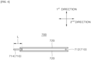
- the electrode 710 of the unit cell 700 may include a body 712 and an electrode tab 714 ( FIG. 4 ).
- the body 712 may be bonded to the separator 720 in the first direction.
- the electrode tab 714 may protrude further outward than the body 712 and the separator 720 bonded to the body 712.
- the electrode tab 714 may protrude further than the body 712 and the separator 720 bonded to the body 712 in one direction (e.g., front direction) of a second direction (e.g., front and rear directions) that intersects the first direction ( FIG. 4 ).
- the electrode tab 714 may be coupled to the body 712 and protrude from one end (e.g., front end) of the body 712 in one direction (e.g., front direction) of the second direction ( FIG. 4 ).
- an apparatus of manufacturing electrode assembly 1 may include a unit cell supply unit 10 and a unit cell transport unit 50.
- the unit cell transport unit 50 will be described first, and the unit cell supply unit 10 will be described thereafter.
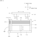
- the unit cell transport unit 50 may extract from the magazine 100 and transport a unit cell 700 at one end (e.g. upper end) of the unit cells 700 stacked in the magazine 100 of the unit cell supply unit 10 in one direction of the first direction (e.g., upward and downward directions).
- a unit cell 700 at one end (e.g. upper end) of the unit cells 700 stacked in the magazine 100 of the unit cell supply unit 10 in one direction of the first direction (e.g., upward and downward directions).
- the unit cell transport unit 50 may include a suction unit 52 and a transport frame 54.
- the suction unit 52 may move in vertical direction.
- the suction unit 52 may adhere to and lift the unit cells 700 at one end of the unit cells 700 stacked in the first direction. That is, the suction unit 52 may extract the unit cell 700 from the magazine 100.
- the magazine 100 may include a base 110 and a guide frame 120. Additionally, the magazine 100 may further include an elevating plate 130 and an elevator column 140. The elevating plate 130 and elevator column 140 may be optional.
- the base 110 may constitute a basis of the magazine 100.
- the guide frame 120, thee elevating plate 130 and the elevator column 140 may be installed on the base 110.
- the guide frame 120 may be installed on the base 110 and may extend in the first direction.
- the guide frame 120 may at least partially surround the outer periphery of the unit cells 700 stacked on the base 110.
- the guide frame 120 may be in contact with the outer periphery of the unit cell 700.
- a plurality of guide frames 120 may be provided corresponding to the number of corners of the unit cell 700.
- the guide frames 120 may be disposed at locations corresponding to the corners of the unit cells 700, respectively, and may be disposed spaced apart from one another.
- the cross-section of the guide frame 120 may correspond to the shape of the edge (e.g., 'L' shape) of the unit cell 700 corresponding to each guide frame 120.
- the guide frame 120 may guide the unit cell 700 when inserting the unit cell 700 into the magazine 100. Accordingly, the unit cells 700 may be stacked on the base 110 or the elevating plate 130 while being aligned and may remain aligned.
- the guide frame 120 may at least partially surround the elevating plate 130.
- the guide frame 120 may guide the lifting and lowering of the elevating plate 130.
- the elevating plate 130 may be disposed on the base 110 and may be lifted and lowered.
- One or more unit cells 700 may be stacked on the elevating plate 130 in the first direction.
- the elevator column 140 may be coupled to the lower end of the elevating plate 130 and may be lifted and lowered.
- the elevator column 140 may elevate the elevating plate 130.
- the elevating plate 130 and the elevator column 140 may adjusted in a manner that the position (e.g., height) of the unit cell 700 disposed at one end (e.g., upper end) of the one or more unit cells 700 stacked in the first direction is constant.
- the anti-static unit 200 may be disposed adjacent to the magazine 100.
- the anti-static unit 200 may remove static electricity from the unit cells 700 stacked in the magazine 100.
- the anti-static unit 200 may include a contact body 210 ( FIGS. 1 to 3 ).
- the contact body 210 may be made of a conductive material.
- the contact body 210 may be made of copper.
- the contact body 210 may be in contact with at least one of the one or more unit cells 700 stacked in the magazine 100.
- the contact body 210 may be in contact with at least one of the one or more electrodes 710 of each of the at least one of the one or more unit cells 700 to discharge static electricity from the at least one of the one or more unit cells 700.
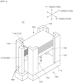
- the contact body 210 may be in contact with eight unit cells 700 stacked in the magazine 100 as shown in FIGS. 1 to 3 .
- the contact body 210 may be in contact with the electrode 710 of each of the eight unit cells (half cells) 700 to discharge static electricity from the one or more unit cells 700.
- the contact body 210 may be in contact with one electrode 710 or two electrodes 710 of each of the eight unit cells (mono cells) 700 to discharge static electricity from the one or more unit cells 700.
- the contact body 210 which is a conductor, is in contact with and electrically connected to the at least one of one or more electrode 710 (conductor) of each of the at least one of the one or more unit cells 700 so as to discharge the static electricity of the unit cell 700 effectively.
- the contact body 210 which is a conductor
- the electrode 710 which is a conductor
- the static electricity of the electrode 710 of the unit cell 700 may be effectively discharged.
- the separator 720 of the unit cell 700 is made of an insulating material, unlike the electrode 710, the static electricity of the separator 720 may be effectively discharged through the electrode 710 bonded to the separator 720.
- the contact body 210 is in contact with the electrode 710 of the unit cell 700, the static electricity of the entirety of the one or more unit cells 700 may be effectively discharged.
- the static electricity of the unit cell 700 is effectively reduced, it is possible to prevent two or more unit cells 700 stacked in the magazine 100 from being extracted simultaneously. That is, individual extraction and supply of the one or more unit cells 700 stacked in the magazine 100 is possible. Accordingly, manufacturing defects of the electrode assembly due to the simultaneous extraction and the transport of two or more unit cells 700 may be prevented, and the interruption of the manufacturing process of the electrode assembly caused by one or more unit cells 700 falling during the transport to block sensors such as cameras may be prevented.
- the unit cell 700 is a half cell in which a separator 720, an electrode 710, and a separator 720 are stacked
- a plurality of half cells stacked in the magazine 100 may be individually extracted and transported from the magazine 100 even after a long-term storage due to the effective discharge of the static electricity of the half cell. Therefore, manufacturing defects of the electrode assembly due to stacking of two or more half cells on the laminate having a plurality of stacked mono cells in each of which separator 720, electrode 710, separator 720, and electrode 710 are stacked caused by the simultaneous extraction and the transport of two or more half cells may be prevented.
- the interruption of the manufacturing process of the electrode assembly caused by the simultaneous extraction and the transport of two or more half cells due to the generation of static electricity due to long-term storage and one or more half cells falling during the transport to block sensors such as cameras may be prevented.
- the contact body 210 may be in contact with the at least one of one or more electrodes 710 of the unit cell 700 disposed at one end (e.g. upper end) of the unit cells 700 stacked in the magazine 100 in the first direction.
- the unit cell transport unit 50 may extract from the magazine 100 and transport the unit cell 700 disposed at one end of the unit cells 700 stacked in the magazine 100 in the first direction as described above.
- the unit cell transport unit 50 extracting from the magazine 100 and transporting the unit cell 700 disposed at one end (e.g. upper end) of the unit cells 700 stacked in the first direction
- the simultaneous extraction and the transport of two or more unit cells 700 disposed at one end of the unit cells 700 stacked in the first direction may be prevented since at least the static electricity of the unit cell 700 disposed at one end of the unit cells 700 stacked in the first direction is discharged by contact body 210.
- the unit cells 700 stacked in the magazine 100 may be reliably and individually extracted and supplied.
- the contact body 210 may be in contact with the electrode 710 of each of the eight unit cells 700 stacked in the magazine 100 to discharge static electricity from the one or more unit cells 700.
- the contact body 210 may be in contact with one electrode 710 or two electrodes 710 of each of the eight unit cells (mono cells) 700 to discharge static electricity from the one or more unit cells 700.
- the contact body 210 which is a conductor, may be electrically connected to the electrode 710 simply and easily.
- manufacturing and maintenance costs of the contact body 210 and the apparatus of manufacturing electrode assembly may be reduced as the structure of the contact body 210 may be simplified.
- the contact body 210 may be in contact with the plurality of unit cells 700 by being in contact with an electrode tab 714 of each of the at least one of the one or more electrodes 710 of the each of the plurality of unit cells 700
- the electrode tab 714 of each of the at least one of the one or more electrodes 710 of each of the plurality of unit cells 700 may protrude further than the body 712 coupled to the electrode tab 714 and the separator 720 bonded to the body 712 in one direction (e.g., front direction) of the second direction (e.g., front and rear directions).
- the contact body 210 may extend in the first direction to be in contact with the electrode tab 714 of each of the plurality of unit cells 700, which protrudes further than in one direction of the second direction ( FIGS. 1 to 3 ).
- the static electricity of the plurality of unit cells 700 stacked in the magazine 100 may be effectively discharged by the contact body 210 extending in the first direction.
- the manufacturing and maintenance costs of the contact body 210 and the apparatus of manufacturing electrode assembly may be reduced since the configuration of the electrode assembly may be simplified.
- the contact body 210 may be disposed at one side of the electrode tab 714 of each of the at least one of the one or more electrodes 710 of each of the at least one of the one or more unit cells 700 in the second direction.
- the contact body 210 may be in contact with the electrode tab 714 of each of the at least one of the one or more electrodes 710 of each of the at least one of the one or more unit cells 700 in the second direction ( FIG. 1 to FIG. 3 ).
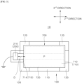
- the body 712 of each of the at least one of the one or more electrodes 710 of each of the at least one of the one or more unit cells 700 may include an overlapping portion P overlapping with the electrode tab 714 coupled to the body 712 in the third direction ( FIG. 3 ).
- the distance D ( FIG. 3 ) in the second direction between the overlapping portion P of each of the at least one of the one or more electrodes 710 of each of the at least one of the one or more unit cells 700 and the contact body 210 may be shorter than a length L ( FIG. 4 ) in the second direction of the electrode tab 714 of each of the at least one of the one or more electrodes 710 of each of the at least one of the one or more unit cells 700.
- the distance D between the contact body 210 and the body 712 with the electrode tab 714 therebetween may be shortened such that the contact body 210 may reliably be in contact with the electrode tab 714. Accordingly, since the static electricity may be reliably discharged from the unit cells 700 through the contact body 210, the unit cells 700 stacked in the magazine 100 may be reliably extracted and supplied individually.
- the value obtained by subtracting the distance D from the length L may be greater than zero and equal to or less than 1/15 of the length L.
- the distance D in the second direction between the overlapping portion P and the contact body 210 may be less than 15 mm (millimeters) and equal to or greater than 14 mm (millimeters).
- the electrode tab 714 may be prevented from having excessive pressure applied thereto by the contact body 210.
- the electrode tab 714 may not be damaged or deformed while the contact body 210 is reliably brought into contact with the electrode tab 714.
- the contact body 210 and the electrode tab 714 may be made of the same material.
- the contact body 210 may also be made of copper.
- the contact body 210 may be grounded ( FIGS. 1 to 3 ).
- the unit cells 700 stacked in the magazine 100 may be reliably and individually extracted and supplied as the static electricity of the unit cell 700 may be reliably discharged through the grounded contact body 210.
- the unit cell supply unit 10 may include a magazine 100 and an anti-static unit 200 as shown in FIGS. 1 to 3 .
- the description will be focused on the differences from those shown in FIGS. 1 to 3 .
- the anti-static unit 200 may further include a blower type ionizer 220.
- the blower type ionizer 220 generates ions and blows ionized air containing the generated ions toward the unit cell 700 stacked in the magazine 100 to remove static electricity from the unit cell 700.
- the static electricity of the unit cell 700 may be reliably removed through the contact body 210 and the blower type ionizer 220 such that the unit cells 700 stacked in the magazine 100 may be reliably and individually extracted and supplied.
- the blower type ionizer 220 may blow ionized air toward at least one unit cell 700 disposed at one end of the one or more unit cells 700 stacked in the magazine 100 in the first direction.
- the unit cell transport unit 50 may extract from the magazine 100 and transport the unit cell 700 disposed at one end of the one or more unit cells 700 stacked in the magazine 100 in the first direction as described above.
- the unit cell transport unit 50 extracts from the magazine 100 and transports the unit cell 700 disposed at one end (e.g., upper end) of the one or more unit cells 700 stacked in the first direction
- the static electricity of at least one unit cell 700 disposed at one end of the one or more unit cells 700 stacked in the first direction is removed by the blower type ionizer 220 such that the unit cell transport unit 50 may be prevented from extracting and transporting two or more unit cells 700 disposed at one end of the one or more unit cells 700. Therefore, the unit cells 700 stacked in the magazine 100 may be reliably and individually extracted and supplied.
- the contact body 210 may be in contact with the electrode tab 714 of each of the one or more electrodes 710 of each of the at least one of the one or more unit cells 700 stacked in the magazine 100.
- the at least one of the one or more unit cells 700 stacked in the magazine 100 may refer to the entirety of unit cells 700 stacked in the magazine 100
- the one or more electrodes 710 of each of the at least one of the one or more unit cells 700 stacked in the magazine 100 may refer to the entirety of electrodes 710 of the entirety of the unit cells 700.
- the first blower type ionizer 222 may be disposed at one side (e.g., left side) of the one or more unit cells 700 in the above-described third direction (e.g., left and right directions) and blow the ionized air toward the one or more unit cells 700.
- the second blower type ionizer 224 may be disposed at the other side (e.g., right side) of the one or more unit cells 700 in the third direction and blow ionized air toward the unit cell 700.
- the first, the second and the third blower type ionizers 222, 224 and 226 partially surround the one or more unit cells 700 and blow a large amount of ionized air from various directions toward the unit cell 700, thereby removing the static electricity of the one or more unit cells 700 effectively and reliably.
- every electrode tab 714 of every unit cell 700 may protrude in one direction of the second direction, and the contact body 210 in contact with every electrode tabs 714 of every unit cell 700 may be disposed at one side of the unit cells 700 in the second direction.
- the static electricity of every unit cell 700 may be effectively discharged by the contact body 210 having a simple shape (e.g., a bar shape extending in the first direction) and configuration (e.g., only one). Accordingly, manufacturing and maintenance costs of the contact body 210 and the apparatus of manufacturing electrode assembly may be reduced.
- every electrode tab 714 of every unit cell 700 may protrude in one direction of the second direction, it is sufficient that the blower type ionizer 220 is not disposed at one side of the unit cells 700 in the second direction to prevent damage or deformation of the electrode tabs 714. That is, the first, the second and the third blower type ionizers 222, 224 and 226 may be disposed at the other side of the unit cells 700 in the second direction and one and the other sides of the unit cells 700 in the third direction except one side of the unit cells 700 in the second direction. Therefore, the number of directions in which ionized air may be blown toward the unit cell 700 may increase and the amount of blown ionized air may increase. Thus, static electricity of the unit cell 700 may be effectively and reliably removed.
- a method of manufacturing an electrode assembly using the above-described apparatus of manufacturing electrode assembly may include a unit cell supply step.
- the contact body 210 may be brought into contact with one or more electrodes 710 of at least one unit cell 700 disposed at one end (e.g., upper end) of one or more unit cells 700 stacked in the magazine 100 in the first direction.
- the contact body 210 may be brought into contact with the one or more unit cells 700 stacked in the magazine 100 by bringing the contact body 210 into contact with the electrode tab 714 of each of the at least one of the one or more electrodes 710 of each of the one or more unit cells 700.
- the contact body 210 may be brought into contact with the electrode tab 714 of each of the at least one of the one or more electrodes 710 of each of the one or more unit cells 700 in the second direction.
- the contact body 210 may be brought into contact with each of the at least one of the one or more electrodes 710 in the second direction such that the distance D ( FIG. 3 ) in the second direction between the overlapping portion P of each of the at least one of the one or more electrodes 710 of each of the one or more unit cells 700 and the contact body 210 may be shorter than a length L ( FIG. 4 ) in the second direction of the electrode tab 714 of each of the at least one of the one or more electrodes 710 of each of the one or more unit cells 700.
- ions may be generated and ionized air containing the generated ions may be blown toward the unit cell 700 stacked in the magazine 100.
Landscapes
- Engineering & Computer Science (AREA)
- Manufacturing & Machinery (AREA)
- Chemical & Material Sciences (AREA)
- Chemical Kinetics & Catalysis (AREA)
- Electrochemistry (AREA)
- General Chemical & Material Sciences (AREA)
- Secondary Cells (AREA)
- Connection Of Batteries Or Terminals (AREA)
Abstract
Description
- This application claims the benefit of priority based on
Korean Patent Application No. 10-2022-0068090, dated June 3, 2022 - The present invention relates to apparatus and method of manufacturing electrode assembly, and more particularly, to apparatus and method of manufacturing electrode assembly capable of individually extracting and supplying unit cells stacked in a magazine.
- Generally, a secondary battery refers to a battery that may be charged and discharged, unlike primary batteries that cannot be recharged. These secondary batteries are used in small, high-tech electronic devices such as mobile phones, PDAs and laptop computers as well as in energy storage systems (ESS), electric vehicles (EV) or hybrid electric vehicles (HEV) as a power source.
- Secondary batteries are classified into can-type secondary batteries wherein the electrode assembly is embedded in a metal can, and pouch-type secondary batteries wherein the electrode assembly is embedded in a pouch (battery case). Pouch-type secondary batteries include an electrode assembly and a pouch (battery case) that accommodates the electrode assembly. The electrode assembly includes one or more unit cells, and each of the unit cells have a structure in which electrodes and separators are alternately stacked.
- Meanwhile, the electrode assembly is manufactured using an apparatus of manufacturing electrode assembly, which includes a magazine in which the one or more unit cells are stacked, a transport unit that adheres the one or more unit cells stacked in the magazine, and then stacks the same at a predetermined location.
- However, when the apparatus of manufacturing electrode assembly adheres the unit cells stacked at the top of the magazine, there is a problem in that two or more unit cells stacked at the top of the magazine are extract together due to static electricity.
- (Patent document 0001)
Korean Patent Application Publication 10-2021-0047209 - In order to solve the above-described problems, it is an object of the present invention to provide apparatus and method of manufacturing electrode assembly capable of individually extracting and supplying unit cells stacked in a magazine.
- It is an object of the present invention to provide an apparatus of manufacturing electrode assembly that has a simple structure and configuration and reduces manufacturing and maintenance costs.
- It is an object of the present invention to provide an apparatus of manufacturing electrode assembly that does not cause damage or deformation of unit cells and produce foreign matter.
- It is an object of the present invention to provide an apparatus of manufacturing electrode assembly that provides simple and easy operation.
- The technical problems to be solved by the present invention are not limited to the objects described above, and other objects and advantages of the present invention that are not described may be understood through the following description and will be more clearly understood by the examples of the present invention. Additionally, it is apparent that the objects and advantages of the present invention may be embodied by the means and combinations thereof indicated in the claims.
- In order to solve the above-described problems, the present invention provides an apparatus of manufacturing electrode assembly including a unit
cell supply unit 10 and a unitcell transport unit 50. - The unit
cell supply unit 10 may include amagazine 100 and ananti-static unit 200. - One or
more unit cells 700 may be stacked in the first direction in themagazine 100. - The
anti-static unit 200 may be placed adjacent to themagazine 100. - The
anti-static unit 200 may remove static electricity from at least one of the one ormore unit cells 700 stacked in themagazine 100. - The unit
cell transport unit 50 may extract from themagazine 100 and transport the one ormore unit cells 700 stacked in themagazine 100. - Each of the one or
more unit cells 700 may include one ormore electrodes 710 and one ormore separators 720. - The one or
more electrodes 710 and one ormore separators 720 may be alternately stacked in the first direction. - The one or
more electrodes 710 and one ormore separators 720 may be bonded to each other in the first direction. - The
anti-static unit 200 may include acontact body 210 made of a conductive material. - The
contact body 210 is in contact with the at least one of the one ormore unit cells 700 to discharge static electricity from the at least one of the one ormore unit cells 700 by being in contact with anelectrode tab 714 of each of at least one of the one ormore electrodes 710 of each of the at least one of the one or more unit cells. - The
electrode tab 714 of each of the at least one of the one ormore electrodes 710 of each of the at least one of the one ormore unit cells 700 protrudes in one direction of a second direction intersecting the first direction. - The
contact body 210 may be disposed at one side of theelectrode tab 714 in the second direction. - In one embodiment, the at least one of the one or
more unit cells 700 may comprise oneunit cell 700 disposed at one end of the one ormore unit cells 700 stacked in themagazine 100 in the first direction - The unit
cell transport unit 50 may extract from themagazine 100 and transport the oneunit cell 700 of the one ormore unit cells 700 stacked in themagazine 100 in the first direction. - In one embodiment, each of the at least one of the one or
more electrodes 710 of each of the at least one of the one ormore unit cells 700 may include abody 712 and anelectrode tab 714. - The
body 712 may be bonded to the one ormore separators 720 in the first direction. - The
electrode tab 714 may protrude further than thebody 712 and the one ormore separators 720 bonded to thebody 712 in one direction of the second direction. - The
electrode tab 714 may be coupled to thebody 712. - In one embodiment, the at least one of the one or
more unit cells 700 may be a plurality ofunit cells 700. - The
contact body 210 may extend in the first direction to be in contact with theelectrode tab 714 of each of the plurality ofunit cells 700 wherein theelectrode tab 714 protrudes further than thebody 712 and the one ormore separators 720 in one direction of the second direction - In one embodiment, the
contact body 210 may be in contact with theelectrode tab 714 of each of the at least one of the one ormore electrodes 710 of each of the at least one of the one ormore unit cells 700 in the second direction. - When projected perpendicularly to an arbitrary plane extending in the second direction and a third direction intersecting the first direction and the second direction, the
body 712 of each of the at least one of the one ormore electrodes 710 of each of the at least one of the one ormore unit cells 700 may include an overlapping portion P overlapping with theelectrode tab 714 coupled to thebody 712 in the third direction. - A distance D in the second direction between the overlapping portion P of each of the at least one of the one or
more electrodes 710 of each of the at least one of the one ormore unit cells 700 and thecontact body 210 may be shorter than a length L in the second direction of theelectrode tab 714 of each of the at least one of the one ormore electrodes 710 of each of the at least one of the one ormore unit cells 700. - In one embodiment, the value obtained by subtracting the distance D from the length L may be greater than zero and equal to or less than 1/15 of the length L.
- In one embodiment, the
contact body 210 and theelectrode tab 714 may be made of the same material. - In one embodiment, the
contact body 210 may be grounded. - In one embodiment, the
anti-static unit 200 may further include ablower type ionizer 220. - The
blower type ionizer 220 may generate ions and blow ionized air containing generated ions toward the one ormore unit cells 700 stacked in themagazine 100 to remove the static electricity from the at least one of the one ormore unit cells 700. - In one embodiment, the unit
cell transport unit 50 may extract from themagazine 100 and transports oneunit cell 700 disposed at one end of the one ormore unit cells 700 stacked in themagazine 100 in the first direction. - The
blower type ionizer 220 may blow the ionized air toward at least the oneunit cell 700 disposed at one end of the one ormore unit cells 700 stacked in themagazine 100 in the first direction.. - In one embodiment, the
blower type ionizer 220 may include a firstblower type ionizer 222, a secondblower type ionizer 224 and a thirdblower type ionizer 226. - The first
blower type ionizer 222 may be disposed at one side of the one ormore unit cells 700 in a third direction intersecting the first and the second directions and blow the ionized air toward the one ormore unit cells 700. - The second
blower type ionizer 224 may be disposed at the other side of the one ormore unit cells 700 in the third direction and blow the ionized air toward the one ormore unit cells 700. - The third
blower type ionizer 226 may be disposed at the other side of the one ormore unit cells 700 in the second direction and blow the ionized air toward the one ormore unit cells 700. - In order to solve the above-described problems, the present invention provides a method of manufacturing an electrode assembly including a unit cell supply step of individually extracting and supplying the one or
more unit cells 700 stacked in themagazine 100. - In the unit cell supply step, the
contact body 210 may be brought into contact with theelectrode tab 714 of each of the at least one of the one ormore electrodes 710 of each of the at least one of the one ormore unit cells 700. - According to embodiments of the present invention, the apparatus of
manufacturing electrode assembly 1 may include a unitcell supply unit 10 including: amagazine 100 having therein one ormore unit cells 700 stacked in a first direction; and ananti-static unit 200 arranged adjacent to themagazine 100 and removing static electricity from at least one of the one ormore unit cells 700 stacked in themagazine 100. Each of the one ormore unit cells 700 may include one ormore electrodes 710 and one ormore separators 720 alternately stacked and bonded to each other in the first direction. Theanti-static unit 200 may include acontact body 210 made of a conductive material wherein thecontact body 210 is in contact with the at least one of the one ormore unit cells 700 to discharge static electricity from the at least one of the one ormore unit cells 700 by being in contact with anelectrode tab 714 of each of at least one of the one ormore electrodes 710 of the each of the at least one of the one ormore unit cells 700. - Accordingly, the
contact body 210, which is a conductor, is in contact with and is electrically connected to the at least one of the one or more electrodes 710 (conductor) of each of the at least one of the one ormore unit cells 700 such that the static electricity of theunit cell 700 may be effectively discharged. - Specifically, since the
contact body 210, which is a conductor, is in contact with and is electrically connected to theelectrode 710, the static electricity of theelectrode 710 of theunit cell 700 may be effectively discharged. In addition, even when theseparator 720 of theunit cell 700 is made of an insulating material unlike theelectrode 710, the static electricity of theseparator 720 may be effectively discharged through theelectrode 710 bonded to theseparator 720. Accordingly, even when thecontact body 210 is in contact with theelectrode 710 of theunit cell 700, the static electricity of theentire unit cell 700 may be effectively discharged. - Thus, since the static electricity of the
unit cell 700 may be effectively reduced, it is possible to prevent two ormore unit cells 700 stacked in themagazine 100 from being extracted together. That is, individual extraction and supply of the one ormore unit cells 700 stacked in themagazine 100 is possible. Accordingly, manufacturing defects of the electrode assembly due to the simultaneous extraction and the transport of two ormore unit cells 700 may be prevented, and the interruption of the manufacturing process of the electrode assembly caused by one ormore unit cells 700 falling during the transport to block sensors such as cameras may be prevented. - In particular, when the
unit cell 700 is a half cell in which theseparator 720, theelectrode 710 and theseparator 720 are stacked, each half cell of a plurality of half cells stacked in themagazine 100 may be individually extracted and transported from themagazine 100 even after long-term storage due to the effective discharge of the static electricity of the plurality of half cells. Therefore, the manufacturing defects of the electrode assembly caused by stacking of two or more half cells on top of laminate in which a plurality of mono cells having a stacked structure ofseparator 720,electrode 710,separator 720 andelectrode 710 are stacked due to the generation of static electricity during long-term storage causing the extraction and the transport of two or more half cells from themagazine 100 may be prevented. In addition, the interruption of the manufacturing process of the electrode assembly caused by one or more half cells falling during the extraction and the transport of two or more half cells to block sensors such as cameras due to the generation of static electricity during to long-term storage may be prevented. - According to embodiments of the present invention, a unit
cell transport unit 50 extracting from themagazine 100 and transporting oneunit cell 700 disposed at one end of the one ormore unit cells 700 stacked in themagazine 100 in the first direction may be further included. Thecontact body 210 may be at least in contact with the at least one of the one ormore electrodes 710 of the oneunit cell 700 disposed at one end of the one ormore unit cells 700 stacked in the first direction. - Accordingly, when the unit
cell transport unit 50 extracts from themagazine 100 and transports theunit cell 700 disposed at one end (e.g., upper end) of the one ormore unit cells 700 stacked in the first direction, at least the static electricity of theunit cell 700 at one end in the first direction is discharged by thecontact body 210, thereby preventing the unitcell transport unit 50 from simultaneously extracting and transporting two ormore unit cells 700 disposed at one end of the one ormore unit cells 700 stacked in the first direction. Accordingly, each of the one ormore unit cells 700 stacked in themagazine 100 may be reliably extracted and supplied individually. - According to embodiments of the present invention, The
electrode 710 of theunit cell 700 may include: abody 712 bonded to theseparator 720 in the first direction; and theelectrode tab 714 coupled to thebody 712 and protruding further outward than thebody 712 and theseparator 720 bonded to thebody 712. Thecontact body 210 may be in contact with theelectrode tab 714 of theelectrode 710 of each of the at least one of the one ormore unit cells 700 to discharge static electricity from theunit cell 700. - Accordingly, the
contact body 210, which is a conductor, may be in contact with theelectrode tab 714 protruding outward to be electrically connected to theelectrode 710 simply and easily. Accordingly, since the structure of thecontact body 210 may be simplified, manufacturing and maintenance costs of thecontact body 210 and the apparatus of manufacturing electrode assembly may be reduced. - According to embodiments of the present invention, the
contact body 210 is in contact with a plurality ofunit cells 700 by being in contact with theelectrode tab 714 of each of the at least one of the one ormore electrodes 710 of each of the plurality ofunit cells 700. Theelectrode tab 714 of each of the at least one of the one ormore electrodes 710 of each of the plurality ofunit cells 700 may protrude further than thebody 712 coupled to theelectrode tab 714 and theseparator 720 bonded to thebody 712 toward one direction of the second direction that intersects the first direction. Thecontact body 210 may extend in the first direction to be in contact with theelectrode tab 714 of each of the plurality ofunit cells 700, which protrudes further than in one direction of the second direction - Accordingly, the static electricity of the plurality of
unit cells 700 stacked in themagazine 100 may be effectively discharged by thecontact body 210 extending in the first direction. Thus, the manufacturing and maintenance costs of thecontact body 210 and the apparatus of manufacturing electrode assembly may be reduced since the configuration of the electrode assembly may be simplified,. - According to embodiments of the present invention, the
electrode tab 714 of each of the at least one of the one ormore electrodes 710 of each of the at least one of the one ormore unit cells 700 may protrude further than thebody 712 coupled to theelectrode tab 714 and theseparator 720 bonded to thebody 712 toward one direction of the second direction that intersects the first direction. Thecontact body 210 may be disposed at one side of theelectrode tab 714 of each of the at least one of the one ormore electrodes 710 of each of the at least one of the one ormore unit cells 700 in the second direction, and be in contact with theelectrode tab 714 of each of the at least one of the one ormore electrodes 710 of each of the at least one of the one ormore unit cells 700 in the second direction. - Accordingly, since the
contact body 210 is in contact with the protruding end (one side end of the second direction) of theelectrode tab 714, that is, with the free end of theelectrode tab 714, theelectrode tab 714 may not be significantly damaged or deformed due to thecontact body 210 applying pressure to theelectrode tab 714 in the second direction. - In addition, the
contact body 210 may be easily brought into contact with theelectrode tab 714 or separated from theelectrode tab 714 as necessary while moving thecontact body 210 relatively from theunit cell 700 and themagazine 100 in the second direction. Accordingly, the operation of the unitcell supply unit 10 of the apparatus ofmanufacturing electrode assembly 1 may be simplified and facilitated. - According to embodiments of the present invention, when projected perpendicularly to an arbitrary plane extending in the second direction and a third direction intersecting the first direction and the second direction, the
body 712 of each of the at least one of the one ormore electrodes 710 of each of the at least one of the one ormore unit cells 700 may include an overlapping portion P overlapping with theelectrode tab 714 coupled to thebody 712 in the third direction. A distance D in the second direction between the overlapping portion P of each of the at least one of the one ormore electrodes 710 of each of the at least one of the one ormore unit cells 700 and thecontact body 210 may be shorter than a length L in the second direction of theelectrode tab 714 of each of the at least one of the one ormore electrodes 710 of each of the at least one of the one ormore unit cells 700. - Accordingly, the distance D between the
contact body 210 and thebody 712 with theelectrode tab 714 therebetween may be shortened such that thecontact body 210 may reliably be in contact with theelectrode tab 714. Accordingly, since the static electricity may be reliably discharged from theunit cells 700 through thecontact body 210, theunit cells 700 stacked in themagazine 100 may be reliably extracted and supplied individually. - According to embodiments of the present invention, the value obtained by subtracting the distance D from the length L may be greater than zero and equal to or less than 1/15 of the length L.
- Accordingly, the
electrode tab 714 may be prevented from having excessive pressure applied thereto by thecontact body 210. Thus, theelectrode tab 714 may not be damaged or deformed while thecontact body 210 is reliably brought into contact with theelectrode tab 714. - According to embodiments of the present invention, the
contact body 210 and theelectrode tab 714 may be made of the same material. - Accordingly, even when the
contact body 210 comes in contact with theelectrode tab 714, foreign matter may not stick to theelectrode tab 714. - According to embodiments of the present invention, the
contact body 210 may be grounded. - Accordingly, since the static electricity of the
unit cell 700 may be reliably discharged through the groundedcontact body 210, theunit cells 700 stacked in themagazine 100 may be reliably individually extracted and supplied. - According to embodiments of the present invention, the
anti-static unit 200 may further include ablower type ionizer 220 for removing the static electricity from the at least one of the one ormore unit cells 700 by generating ions and blowing ionized air containing generated ions toward the one ormore unit cells 700 stacked in themagazine 100. - Accordingly, since the static electricity of the
unit cell 700 may be reliably removed through thecontact body 210 and theblower type ionizer 220, theunit cells 700 stacked in themagazine 100 may be reliably and individually extracted and supplied. - According to embodiments of the present invention, a unit
cell transport unit 50 extracting from themagazine 100 and transporting theunit cell 700 disposed at one end of the one ormore unit cells 700 stacked in themagazine 100 in the first direction may be further included. Theblower type ionizer 220 may blow ionized air toward at least oneunit cell 700 disposed at one end of the one ormore unit cells 700 stacked in themagazine 100 in the first direction. - Accordingly, when the unit
cell transport unit 50 extracts from themagazine 100 and transports theunit cell 700 disposed at one end (e.g., upper end) of the one ormore unit cells 700 stacked in the first direction, the static electricity of at least oneunit cell 700 disposed at one end of the one ormore unit cells 700 stacked in the first direction is removed by theblower type ionizer 220 such that the unitcell transport unit 50 may be prevented from extracting and transporting two ormore unit cells 700 disposed at one end of the one ormore unit cells 700. Therefore, theunit cells 700 stacked in themagazine 100 may be reliably and individually extracted and supplied. - Each of the one or
more electrodes 710 of each of the at least one of the one ormore unit cells 700 may include abody 712 bonded to the one ormore separator 720 in the first direction; and theelectrode tab 714 coupled to thebody 712, protruding from one end of thebody 712 in the second direction toward one direction of the second direction and protruding further than the one ormore separator 720 bonded to thebody 712 in one direction of the second direction. Thecontact body 210 may be disposed at one side of theelectrode tab 714 of the one ormore electrodes 710 of the each of the at least one of the one ormore unit cells 700 in the second direction, and be in contact with theelectrode tab 714 of the one ormore electrodes 710 of each of the at least one of the one ormore unit cells 700. Theblower type ionizer 220 may include: a firstblower type ionizer 222 disposed at one side of the one ormore unit cells 700 in a third direction intersecting the first and the second directions and blowing the ionized air toward the one ormore unit cells 700; a secondblower type ionizer 224 disposed at the other side of the one ormore unit cells 700 in the third direction and blowing the ionized air toward the one ormore unit cells 700; and a thirdblower type ionizer 226 disposed at the other side of the one ormore unit cells 700 in the second direction and blowing the ionized air toward the one ormore unit cells 700. - Accordingly, the first, the second and the third
blower type ionizers more unit cells 700 and blow a large amount of ionized air from various directions toward theunit cell 700, thereby removing the static electricity of the one ormore unit cells 700 effectively and reliably. - In addition, since the
blower type ionizer 220 is not disposed at one side of theunit cells 700 in the second direction, the damage or the deformation of theelectrode tab 714 protruding from one end of theunit cell 700 in the second direction toward one direction of the second direction due to the blowing pressure of the ionized air may be prevented. - In addition, every
electrode tab 714 of everyunit cell 700 may protrude in one direction of the second direction, and thecontact body 210 in contact with everyelectrode tabs 714 of everyunit cell 700 may be disposed at one side of theunit cells 700 in the second direction. Thus, the static electricity of everyunit cell 700 may be effectively discharged by thecontact body 210 having a simple shape (e.g., a bar shape extending in the first direction) and configuration (e.g., only one). Accordingly, manufacturing and maintenance costs of thecontact body 210 and the apparatus of manufacturing electrode assembly may be reduced. - In addition, since every
electrode tab 714 of everyunit cell 700 may protrude in one direction of the second direction, it is sufficient that theblower type ionizer 220 is not disposed at one side of theunit cells 700 in the second direction to prevent damage or deformation of theelectrode tabs 714. That is, the first, the second and the thirdblower type ionizers unit cells 700 in the second direction and one and the other sides of theunit cells 700 in the third direction except one side of theunit cells 700 in the second direction. Therefore, the number of directions in which ionized air may be blown toward theunit cell 700 may increase and the amount of blown ionized air may increase. Thus, static electricity of theunit cell 700 may be effectively and reliably removed. - According to embodiments of the present invention, the method of manufacturing the electrode assembly may include a unit cell supply step of individually extracting and supplying
unit cells 700 stacked in themagazine 100. In the unit cell supply step, thecontact body 210 may be brought into contact with the one ormore unit cells 700 stacked in themagazine 100 by bringing thecontact body 210 into contact with the at least one of the one ormore electrodes 710 of each of the one ormore unit cells 700. - Accordingly, since the
contact body 210, which is a conductor, is electrically connected to the at least one of the one or more electrodes 710 (conductor) of each of the one ormore unit cells 700 by being in contact with the one ormore electrodes 710, the static electricity of theunit cell 700 may be effectively discharged. Therefore, it is possible to prevent two ormore unit cells 700 stacked in themagazine 100 from being extracted and supplied simultaneously as the static electricity of theunit cell 700 is effectively reduced. That is, individual extraction and supply of the one ormore unit cells 700 stacked in themagazine 100 is possible. Accordingly, manufacturing defects of the electrode assembly due to the extraction and the transport of two ormore unit cells 700 may be prevented, and the interruption of the manufacturing process of the electrode assembly caused by one ormore unit cells 700 falling during the transport to block sensors such as cameras may be prevented. - In addition to the advantageous effects described above, specific effects of the present invention will be described further while describing specific details of the present invention.
-
-
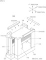
FIG. 1 is a side view schematically illustrating an apparatus of manufacturing electrode assembly and unit cells according to an embodiment of the present invention. -
FIGS. 2 and3 are perspective and plan views schematically illustrating a unit cell supply unit and unit cells of the apparatus of manufacturing electrode assembly ofFIG. 1 , respectively. -
FIG. 4 is a side view specifically illustrating an embodiment of the unit cell ofFIGS. 1 to 3 . -
FIGS. 5 and6 are plan and perspective views schematically illustrating a unit cell supply unit and unit cells according to another embodiment of the present invention. - The above-described objects, features and advantages will be described in detail hereinafter with reference to the accompanying drawings such that those skilled in the art will be able to implement the technical idea of the present invention. In describing the present invention, when it is determined that a detailed description of prior art related to the present invention unnecessarily obscures the gist of the present invention, the detailed description thereof will be omitted. Hereinafter, preferred embodiments according to the present invention will be described in detail with reference to the accompanying drawings. In the drawings, identical reference numerals are used for indicating identical or similar components.
- While "first", "second", etc. are used to describe various elements, these elements are of course not limited by these terms. These terms are only used to distinguish one element from another, and unless specifically stated otherwise, a first element may also be a second element.
- Throughout the specification, unless stated otherwise, each element may be singular or plural.
- Hereinafter, "arranging an element at upper portion (or lower portion) of an element" or "arranging an element at top (or bottom) of an element" refers to not only "arranging an element to be in contact with upper surface (or lower surface)" but also to "arranging an element above upper surface (or lower surface) with another element interposed therebetween."
- Additionally, when an element is described as being "connected to," "coupled with," or "in contact with" another element, it should be understood that the element may be "directly connected to," "directly coupled with," or "directly in contact with" another element, or the element may be "connected to," "coupled with," or "in contact with" another element with yet another element interposed therebetween or via yet another element.
- The expressions in singular form used herein include expressions in plural form unless the context explicitly dictates otherwise. Terms such as "consists of" or "comprises" used herein should not be construed as necessarily including all of the elements or steps described in the specification, and should be construed as not including some of the elements or steps, or including additional elements or steps.
- Additionally, the expressions in singular form used herein include expressions in plural form unless the context explicitly dictates otherwise. Terms such as "consists of" or "comprises" used herein should not be construed as necessarily including all of the elements or steps described in the specification, and should be construed as not including some of the elements or steps, or including additional elements or steps.
-
FIG. 1 is a side view schematically illustrating an apparatus of manufacturing electrode assembly and unit cells according to an embodiment of the present invention,FIGS. 2 and3 are perspective and plan views schematically illustrating a unit cell supply unit and unit cells of the apparatus of manufacturing electrode assembly ofFIG. 1 , respectively,FIG. 4 is a side view specifically illustrating an embodiment of the unit cell ofFIGS. 1 to 3 , andFIGS. 5 and6 are plan and perspective views schematically illustrating a unit cell supply unit and unit cells according to another embodiment of the present invention. - Referring to
FIG. 4 , aunit cell 700 may include one ormore electrodes 710 and one ormore separators 720. The one ormore electrodes 710 and the one ormore separators 720 may be alternately stacked in a first direction (e.g., upward and downward directions) and may be bonded to each other in the first direction. - For example, the
unit cell 700 may be a half cell as shown inFIG. 4 or a mono cell different from the cell shown inFIG. 4 . Additionally, theunit cell 700 may be a cell with a configuration different from those of a half cell and a mono cell. - Here, a half cell may be a cell in which a
separator 720, an electrode 710 (e.g., a cathode) and aseparator 720 are stacked sequentially and bonded to one another as shown inFIG. 4 , and a mono cell, contrary to the half cells shown inFIG. 4 , may be a cell in which aseparator 720, an electrode 710 (e.g., a cathode), aseparator 720 and an electrode 710 (e.g., an anode) are stacked sequentially and bonded one another. - Meanwhile, the electrode assembly (not shown) may be manufactured, for example, by the following method.
- A mono cell laminate is manufactured by stacking a plurality of mono cells in the first direction, and, the manufacturing of a laminate (not shown) is then completed by stacking one more half cell on the mono cell laminate (not shown) in the first direction (e.g., on top). Thereafter, the electrode assembly may be manufactured by wrapping and securing the completed laminate with tape.
- As described above, the laminate is completed by stacking one more half cell on the mono cell laminate at one end thereof in the first direction such that the
electrode 710 of the mono cell of the mono cell laminate at the one end thereof in the first direction is prevented from coming in contact with a battery case (not shown) that accommodates the electrode assembly. - In addition, since only one half cell is necessary to manufacture one electrode assembly, a plurality of half cells manufactured in advance may be in long-term storage. That is, when the
unit cells 700 ofFIGS. 1 to 3 are half cells as shown inFIG. 4 , theunit cells 700 may be stored for a long time in a stacked state as shown inFIGS. 1 to 3 . Accordingly, due to the static electricity generated during the long-term storage, two or more half cells may be extracted and transported simultaneously from themagazine 100, which will be described later. - The
electrode 710 of theunit cell 700 may include abody 712 and an electrode tab 714 (FIG. 4 ). - The
body 712 may be bonded to theseparator 720 in the first direction. - The
electrode tab 714 may protrude further outward than thebody 712 and theseparator 720 bonded to thebody 712. For example, theelectrode tab 714 may protrude further than thebody 712 and theseparator 720 bonded to thebody 712 in one direction (e.g., front direction) of a second direction (e.g., front and rear directions) that intersects the first direction (FIG. 4 ). - Specifically, for example, the
electrode tab 714 may be coupled to thebody 712 and protrude from one end (e.g., front end) of thebody 712 in one direction (e.g., front direction) of the second direction (FIG. 4 ). - Referring to
FIG. 1 , an apparatus ofmanufacturing electrode assembly 1 according to an embodiment may include a unitcell supply unit 10 and a unitcell transport unit 50. The unitcell transport unit 50 will be described first, and the unitcell supply unit 10 will be described thereafter. - The unit
cell transport unit 50, for example, may extract from themagazine 100 and transport aunit cell 700 at one end (e.g. upper end) of theunit cells 700 stacked in themagazine 100 of the unitcell supply unit 10 in one direction of the first direction (e.g., upward and downward directions). - The unit
cell transport unit 50 may include asuction unit 52 and atransport frame 54. - The
suction unit 52 may move in vertical direction. Thesuction unit 52 may adhere to and lift theunit cells 700 at one end of theunit cells 700 stacked in the first direction. That is, thesuction unit 52 may extract theunit cell 700 from themagazine 100. -
Transport frame 54 may be coupled to thesuction unit 52. Thetransport frame 54 may move in horizontal direction. Accordingly, theunit cell 700 adhered to thesuction unit 52 may leave themagazine 100 and be transported to a predetermined location. Here, the predetermined location may be, for example, one end of a new laminate (not shown) having one ormore unit cells 700 stacked in the first direction to manufacture a new electrode assembly. - Referring further to
FIGS. 2 and3 , the unitcell supply unit 10 according to an embodiment of the present invention may include amagazine 100 and ananti-static unit 200. The configuration of each of themagazine 100 and theanti-static unit 200 will be deacribed hereinafter. - One or
more unit cells 700 may be stacked in themagazine 100 in the first direction. For example, eightunit cells 700 are stacked in themagazine 100 inFIGS. 1 and2 . - Specifically, for example, the
magazine 100 may include abase 110 and aguide frame 120. Additionally, themagazine 100 may further include an elevatingplate 130 and anelevator column 140. The elevatingplate 130 andelevator column 140 may be optional. - The base 110 may constitute a basis of the
magazine 100. Theguide frame 120, thee elevatingplate 130 and theelevator column 140 may be installed on thebase 110. - The
guide frame 120 may be installed on thebase 110 and may extend in the first direction. Theguide frame 120 may at least partially surround the outer periphery of theunit cells 700 stacked on thebase 110. Theguide frame 120 may be in contact with the outer periphery of theunit cell 700. - For example, a plurality of guide frames 120 (four guide frames are shown in the drawing) may be provided corresponding to the number of corners of the
unit cell 700. The guide frames 120 may be disposed at locations corresponding to the corners of theunit cells 700, respectively, and may be disposed spaced apart from one another. The cross-section of theguide frame 120 may correspond to the shape of the edge (e.g., 'L' shape) of theunit cell 700 corresponding to eachguide frame 120. - The
guide frame 120 may guide theunit cell 700 when inserting theunit cell 700 into themagazine 100. Accordingly, theunit cells 700 may be stacked on the base 110 or the elevatingplate 130 while being aligned and may remain aligned. - Additionally, the
guide frame 120 may at least partially surround the elevatingplate 130. Theguide frame 120 may guide the lifting and lowering of the elevatingplate 130. - The elevating
plate 130 may be disposed on thebase 110 and may be lifted and lowered. One ormore unit cells 700 may be stacked on the elevatingplate 130 in the first direction. - The
elevator column 140 may be coupled to the lower end of the elevatingplate 130 and may be lifted and lowered. Theelevator column 140 may elevate the elevatingplate 130. - The elevating
plate 130 and theelevator column 140 may adjusted in a manner that the position (e.g., height) of theunit cell 700 disposed at one end (e.g., upper end) of the one ormore unit cells 700 stacked in the first direction is constant. - The
anti-static unit 200 may be disposed adjacent to themagazine 100. Theanti-static unit 200 may remove static electricity from theunit cells 700 stacked in themagazine 100. - The
anti-static unit 200 may include a contact body 210 (FIGS. 1 to 3 ). - The
contact body 210 may be made of a conductive material. For example, thecontact body 210 may be made of copper. - The
contact body 210 may be in contact with at least one of the one ormore unit cells 700 stacked in themagazine 100. Here, thecontact body 210 may be in contact with at least one of the one ormore electrodes 710 of each of the at least one of the one ormore unit cells 700 to discharge static electricity from the at least one of the one ormore unit cells 700. - For example, the
contact body 210 may be in contact with eightunit cells 700 stacked in themagazine 100 as shown inFIGS. 1 to 3 . Here, when each of the eightunit cells 700 ofFIGS. 1 to 3 is the above-described half cell including oneelectrode 710 as shown inFIG. 4 , thecontact body 210 may be in contact with theelectrode 710 of each of the eight unit cells (half cells) 700 to discharge static electricity from the one ormore unit cells 700. When theunit cell 700 ofFIGS. 1 to 3 is the above-described mono cell including twoelectrodes 710, contrary to the half cells shown inFIG. 4 , thecontact body 210 may be in contact with oneelectrode 710 or twoelectrodes 710 of each of the eight unit cells (mono cells) 700 to discharge static electricity from the one ormore unit cells 700. - Accordingly, the
contact body 210, which is a conductor, is in contact with and electrically connected to the at least one of one or more electrode 710 (conductor) of each of the at least one of the one ormore unit cells 700 so as to discharge the static electricity of theunit cell 700 effectively. - Specifically, since the
contact body 210, which is a conductor, is in contact with and electrically connected to theelectrode 710, which is a conductor, the static electricity of theelectrode 710 of theunit cell 700 may be effectively discharged. In addition, even when theseparator 720 of theunit cell 700 is made of an insulating material, unlike theelectrode 710, the static electricity of theseparator 720 may be effectively discharged through theelectrode 710 bonded to theseparator 720. Thus, even when thecontact body 210 is in contact with theelectrode 710 of theunit cell 700, the static electricity of the entirety of the one ormore unit cells 700 may be effectively discharged. - Therefore, since the static electricity of the
unit cell 700 is effectively reduced, it is possible to prevent two ormore unit cells 700 stacked in themagazine 100 from being extracted simultaneously. That is, individual extraction and supply of the one ormore unit cells 700 stacked in themagazine 100 is possible. Accordingly, manufacturing defects of the electrode assembly due to the simultaneous extraction and the transport of two ormore unit cells 700 may be prevented, and the interruption of the manufacturing process of the electrode assembly caused by one ormore unit cells 700 falling during the transport to block sensors such as cameras may be prevented. - In particular, in case the
unit cell 700 is a half cell in which aseparator 720, anelectrode 710, and aseparator 720 are stacked, a plurality of half cells stacked in themagazine 100 may be individually extracted and transported from themagazine 100 even after a long-term storage due to the effective discharge of the static electricity of the half cell. Therefore, manufacturing defects of the electrode assembly due to stacking of two or more half cells on the laminate having a plurality of stacked mono cells in each of whichseparator 720,electrode 710,separator 720, andelectrode 710 are stacked caused by the simultaneous extraction and the transport of two or more half cells may be prevented. In addition, the interruption of the manufacturing process of the electrode assembly caused by the simultaneous extraction and the transport of two or more half cells due to the generation of static electricity due to long-term storage and one or more half cells falling during the transport to block sensors such as cameras may be prevented. - The
contact body 210 may be in contact with the at least one of one ormore electrodes 710 of theunit cell 700 disposed at one end (e.g. upper end) of theunit cells 700 stacked in themagazine 100 in the first direction. Here, the unitcell transport unit 50 may extract from themagazine 100 and transport theunit cell 700 disposed at one end of theunit cells 700 stacked in themagazine 100 in the first direction as described above. - Accordingly, in case of the unit
cell transport unit 50 extracting from themagazine 100 and transporting theunit cell 700 disposed at one end (e.g. upper end) of theunit cells 700 stacked in the first direction, the simultaneous extraction and the transport of two ormore unit cells 700 disposed at one end of theunit cells 700 stacked in the first direction may be prevented since at least the static electricity of theunit cell 700 disposed at one end of theunit cells 700 stacked in the first direction is discharged bycontact body 210. As a result, theunit cells 700 stacked in themagazine 100 may be reliably and individually extracted and supplied. - The
contact body 210 is in contact with the at least one of the one ormore unit cells 700 by being in contact with theelectrode tab 714 of each of the at least one of the one ormore electrodes 710 of each of the at least one of the one ormore unit cells 700 to discharge static electricity. - For example, when each of the eight
unit cells 700 ofFIGS. 1 to 3 is the above-described half cell including oneelectrode 710 as shown inFIG. 4 , thecontact body 210 may be in contact with theelectrode 710 of each of the eightunit cells 700 stacked in themagazine 100 to discharge static electricity from the one ormore unit cells 700. When theunit cell 700 ofFIGS. 1 to 3 is the above-described mono cell including twoelectrodes 710, contrary to the half cells shown inFIG. 4 , thecontact body 210 may be in contact with oneelectrode 710 or twoelectrodes 710 of each of the eight unit cells (mono cells) 700 to discharge static electricity from the one ormore unit cells 700. - Accordingly, by being in contact with the
electrode tab 714 protruding outward, thecontact body 210, which is a conductor, may be electrically connected to theelectrode 710 simply and easily. As a result, manufacturing and maintenance costs of thecontact body 210 and the apparatus of manufacturing electrode assembly may be reduced as the structure of thecontact body 210 may be simplified. - The
contact body 210 may be in contact with the plurality ofunit cells 700 by being in contact with anelectrode tab 714 of each of the at least one of the one ormore electrodes 710 of the each of the plurality ofunit cells 700 - Here, the
electrode tab 714 of each of the at least one of the one ormore electrodes 710 of each of the plurality ofunit cells 700 may protrude further than thebody 712 coupled to theelectrode tab 714 and theseparator 720 bonded to thebody 712 in one direction (e.g., front direction) of the second direction (e.g., front and rear directions). - The
contact body 210 may extend in the first direction to be in contact with theelectrode tab 714 of each of the plurality ofunit cells 700, which protrudes further than in one direction of the second direction (FIGS. 1 to 3 ). - Accordingly, the static electricity of the plurality of
unit cells 700 stacked in themagazine 100 may be effectively discharged by thecontact body 210 extending in the first direction. Thus, the manufacturing and maintenance costs of thecontact body 210 and the apparatus of manufacturing electrode assembly may be reduced since the configuration of the electrode assembly may be simplified. - In case of the
electrode tab 714 of each of the at least one of the one ormore electrodes 710 of each of the at least one of the one ormore unit cells 700 protruding further than thebody 712 coupled to theelectrode tab 714 and theseparator 720 bonded to thebody 712 in the second direction as described above, thecontact body 210 may be disposed at one side of theelectrode tab 714 of each of the at least one of the one ormore electrodes 710 of each of the at least one of the one ormore unit cells 700 in the second direction. In addition, thecontact body 210 may be in contact with theelectrode tab 714 of each of the at least one of the one ormore electrodes 710 of each of the at least one of the one ormore unit cells 700 in the second direction (FIG. 1 to FIG. 3 ). - Accordingly, since the
contact body 210 is in contact with the protruding end (one side end in the second direction) of theelectrode tab 714, that is, with the free end of theelectrode tab 714, theelectrode tab 714 may not be significantly damaged or deformed due to thecontact body 210 applying pressure to theelectrode tab 714 in the second direction. - In addition, the
contact body 210 may be easily brought into contact with theelectrode tab 714 or separated from theelectrode tab 714 as necessary while moving thecontact body 210 relatively from theunit cell 700 and themagazine 100 in the second direction. Accordingly, the operation of the unitcell supply unit 10 of the apparatus ofmanufacturing electrode assembly 1 may be simplified and facilitated. - Meanwhile, when projected perpendicularly to an arbitrary plane extending in the second direction and the third direction (left and right direction) intersecting the first direction and the second direction, the
body 712 of each of the at least one of the one ormore electrodes 710 of each of the at least one of the one ormore unit cells 700 may include an overlapping portion P overlapping with theelectrode tab 714 coupled to thebody 712 in the third direction (FIG. 3 ). - Here, the distance D (
FIG. 3 ) in the second direction between the overlapping portion P of each of the at least one of the one ormore electrodes 710 of each of the at least one of the one ormore unit cells 700 and thecontact body 210 may be shorter than a length L (FIG. 4 ) in the second direction of theelectrode tab 714 of each of the at least one of the one ormore electrodes 710 of each of the at least one of the one ormore unit cells 700. - Accordingly, the distance D between the
contact body 210 and thebody 712 with theelectrode tab 714 therebetween may be shortened such that thecontact body 210 may reliably be in contact with theelectrode tab 714. Accordingly, since the static electricity may be reliably discharged from theunit cells 700 through thecontact body 210, theunit cells 700 stacked in themagazine 100 may be reliably extracted and supplied individually. - The value obtained by subtracting the distance D from the length L may be greater than zero and equal to or less than 1/15 of the length L. For example, when the length L of the
electrode tab 714 of theelectrode 710 in the second direction is 15 mm (millimeters), the distance D in the second direction between the overlapping portion P and thecontact body 210 may be less than 15 mm (millimeters) and equal to or greater than 14 mm (millimeters). - Accordingly, the
electrode tab 714 may be prevented from having excessive pressure applied thereto by thecontact body 210. Thus, theelectrode tab 714 may not be damaged or deformed while thecontact body 210 is reliably brought into contact with theelectrode tab 714. - The
contact body 210 and theelectrode tab 714 may be made of the same material. For example, when theelectrode tab 714 is made of copper, thecontact body 210 may also be made of copper. - Accordingly, even when the
contact body 210 comes in contact with theelectrode tab 714, foreign matter may not stick to theelectrode tab 714. - The
contact body 210 may be grounded (FIGS. 1 to 3 ). - Accordingly, the
unit cells 700 stacked in themagazine 100 may be reliably and individually extracted and supplied as the static electricity of theunit cell 700 may be reliably discharged through the groundedcontact body 210. - Referring further to
FIGS. 5 and6 , the unitcell supply unit 10 according to another embodiment of the present invention may include amagazine 100 and ananti-static unit 200 as shown inFIGS. 1 to 3 . Hereinafter, the description will be focused on the differences from those shown inFIGS. 1 to 3 . - The
anti-static unit 200 may further include ablower type ionizer 220. - The
blower type ionizer 220 generates ions and blows ionized air containing the generated ions toward theunit cell 700 stacked in themagazine 100 to remove static electricity from theunit cell 700. - Accordingly, the static electricity of the
unit cell 700 may be reliably removed through thecontact body 210 and theblower type ionizer 220 such that theunit cells 700 stacked in themagazine 100 may be reliably and individually extracted and supplied. - The
blower type ionizer 220 may blow ionized air toward at least oneunit cell 700 disposed at one end of the one ormore unit cells 700 stacked in themagazine 100 in the first direction. At this time, the unitcell transport unit 50 may extract from themagazine 100 and transport theunit cell 700 disposed at one end of the one ormore unit cells 700 stacked in themagazine 100 in the first direction as described above. - Accordingly, when the unit
cell transport unit 50 extracts from themagazine 100 and transports theunit cell 700 disposed at one end (e.g., upper end) of the one ormore unit cells 700 stacked in the first direction, the static electricity of at least oneunit cell 700 disposed at one end of the one ormore unit cells 700 stacked in the first direction is removed by theblower type ionizer 220 such that the unitcell transport unit 50 may be prevented from extracting and transporting two ormore unit cells 700 disposed at one end of the one ormore unit cells 700. Therefore, theunit cells 700 stacked in themagazine 100 may be reliably and individually extracted and supplied. - Meanwhile, as described above, the
electrode 710 of theunit cell 700 may include: abody 712 bonded to theseparator 720 in the first direction; and theelectrode tab 714 coupled to thebody 712 and protruding from one end (e.g., front end) of thebody 712 in one direction (e.g., front direction) of the second direction further outward than theseparator 720 bonded to thebody 712. - Here, the
contact body 210 may be disposed at one side in the second direction (e.g., front side) of theelectrode tab 714 of each of the one ormore electrodes 710 of each of the at least one of the one ormore unit cells 700 stacked in themagazine 100. - In addition, the
contact body 210 may be in contact with theelectrode tab 714 of each of the one ormore electrodes 710 of each of the at least one of the one ormore unit cells 700 stacked in themagazine 100. Here, "the at least one of the one ormore unit cells 700 stacked in themagazine 100" may refer to the entirety ofunit cells 700 stacked in themagazine 100, and "the one ormore electrodes 710 of each of the at least one of the one ormore unit cells 700 stacked in themagazine 100" may refer to the entirety ofelectrodes 710 of the entirety of theunit cells 700. - In addition, the
blower type ionizer 220 may include the firstblower type ionizer 222, the secondblower type ionizer 224 and the thirdblower type ionizer 226. - The first
blower type ionizer 222 may be disposed at one side (e.g., left side) of the one ormore unit cells 700 in the above-described third direction (e.g., left and right directions) and blow the ionized air toward the one ormore unit cells 700. - The second
blower type ionizer 224 may be disposed at the other side (e.g., right side) of the one ormore unit cells 700 in the third direction and blow ionized air toward theunit cell 700. - The third
blower type ionizer 226 may be disposed at the other side (e.g., rear side) of the one ormore unit cells 700 in the second direction and blow ionized air toward theunit cell 700. - Accordingly, the first, the second and the third
blower type ionizers more unit cells 700 and blow a large amount of ionized air from various directions toward theunit cell 700, thereby removing the static electricity of the one ormore unit cells 700 effectively and reliably. - In addition, since the
blower type ionizer 220 is not disposed at one side of theunit cells 700 in the second direction, the damage or the deformation of theelectrode tab 714 protruding from one end of theunit cell 700 in the second direction toward one direction of the second direction due to the blowing pressure of the ionized air may be prevented. - In addition, every
electrode tab 714 of everyunit cell 700 may protrude in one direction of the second direction, and thecontact body 210 in contact with everyelectrode tabs 714 of everyunit cell 700 may be disposed at one side of theunit cells 700 in the second direction. Thus, the static electricity of everyunit cell 700 may be effectively discharged by thecontact body 210 having a simple shape (e.g., a bar shape extending in the first direction) and configuration (e.g., only one). Accordingly, manufacturing and maintenance costs of thecontact body 210 and the apparatus of manufacturing electrode assembly may be reduced. - In addition, since every
electrode tab 714 of everyunit cell 700 may protrude in one direction of the second direction, it is sufficient that theblower type ionizer 220 is not disposed at one side of theunit cells 700 in the second direction to prevent damage or deformation of theelectrode tabs 714. That is, the first, the second and the thirdblower type ionizers unit cells 700 in the second direction and one and the other sides of theunit cells 700 in the third direction except one side of theunit cells 700 in the second direction. Therefore, the number of directions in which ionized air may be blown toward theunit cell 700 may increase and the amount of blown ionized air may increase. Thus, static electricity of theunit cell 700 may be effectively and reliably removed. - According to an embodiment of the present invention, a method of manufacturing an electrode assembly using the above-described apparatus of manufacturing electrode assembly may include a unit cell supply step.
- In the unit cell supply step, the
contact body 210 may be brought into contact with theelectrode tab 714 of each of the at least one of the one ormore electrodes 710 of each of the one ormore unit cells 700. - Accordingly, since the
contact body 210, which is a conductor, is electrically connected to the at least one of the one or more electrodes 710 (conductor) of each of the one ormore unit cells 700 by being in contact with the one ormore electrodes 710, the static electricity of theunit cell 700 may be effectively discharged. Therefore, it is possible to prevent two ormore unit cells 700 stacked in themagazine 100 from being extracted and supplied simultaneously as the static electricity of theunit cell 700 is effectively reduced. That is, individual extraction and supply of the one ormore unit cells 700 stacked in themagazine 100 is possible. Accordingly, manufacturing defects of the electrode assembly due to the extraction and the transport of two ormore unit cells 700 may be prevented, and the interruption of the manufacturing process of the electrode assembly caused by one ormore unit cells 700 falling during the transport to block sensors such as cameras may be prevented. - In addition, the
contact body 210 may be brought into contact with one ormore electrodes 710 of at least oneunit cell 700 disposed at one end (e.g., upper end) of one ormore unit cells 700 stacked in themagazine 100 in the first direction. - In addition, the
contact body 210 may be brought into contact with the one ormore unit cells 700 stacked in themagazine 100 by bringing thecontact body 210 into contact with theelectrode tab 714 of each of the at least one of the one ormore electrodes 710 of each of the one ormore unit cells 700. - Additionally, the
contact body 210 may be brought into contact with theelectrode tab 714 of each of the at least one of the one ormore electrodes 710 of each of the one ormore unit cells 700 in the second direction. - Here, the
contact body 210 may be brought into contact with each of the at least one of the one ormore electrodes 710 in the second direction such that the distance D (FIG. 3 ) in the second direction between the overlapping portion P of each of the at least one of the one ormore electrodes 710 of each of the one ormore unit cells 700 and thecontact body 210 may be shorter than a length L (FIG. 4 ) in the second direction of theelectrode tab 714 of each of the at least one of the one ormore electrodes 710 of each of the one ormore unit cells 700. - Additionally, the
contact body 210 may be grounded. - Additionally, by operating the
blower type ionizer 220, ions may be generated and ionized air containing the generated ions may be blown toward theunit cell 700 stacked in themagazine 100. - The above-described embodiments should be understood in all respects as illustrative and not restrictive, and the scope of the present invention will be represented by the claims to be described later rather than the detailed description given above. In addition, all changes and modifications derived from the equivalent concept as well as the meaning and scope of the patent claims to be described later should be construed as being included in the scope of the present invention.
- As described above, the present invention has been described with reference to the illustrative drawings, but the present invention is not limited to the embodiments and drawings disclosed herein, and various modifications may be made by those skilled in the art within the scope of the technical idea of the present invention. It is obvious that transformation may occur. In addition, although the operational effects according to the configuration of the present invention were not explicitly described and explained while explaining the embodiments of the present invention above, it is natural that the predictable effects due to the configuration should also be recognized.
-
1: apparatus of manufacturing electrode assembly 10: unit cell supply unit 100: magazine 110: base 120: guide frame 130: elevating plate 140: elevator column 200: anti-static unit 210: laminate 220: blower type ionizer 222: first blower type ionizer 224: second blower type ionizer 226: third blower type ionizer 50: unit cell transport unit 52: suction unit 54: transport frame 700: unit cell 710: electrode 712: body 714: electrode tab 720: separator
Claims (13)
- An apparatus of manufacturing an electrode assembly, comprising:a unit cell supply unit 10 comprising: a magazine 100 having therein one or more unit cells 700 stacked in a first direction; and an anti-static unit 200 arranged adjacent to the magazine 100 and removing static electricity from at least one of the one or more unit cells 700 stacked in the magazine 100; anda unit cell transport unit 50 extracting from the magazine 100 and transporting the one or more unit cells 700 stacked in the magazine 100,wherein each of the one or more unit cells 700 comprises one or more electrodes 710 and one or more separators 720 alternately stacked and bonded to each other in the first direction,the anti-static unit 200 comprises a contact body 210 made of a conductive material, the contact body 210 being in contact with the at least one of the one or more unit cells 700 to discharge static electricity from the at least one of the one or more unit cells 700 by being in contact with an electrode tab 714 of each of at least one of the one or more electrodes 710 of each of the at least one of the one or more unit cells 700,the electrode tab 714 of each of the at least one of the one or more electrodes 710 of each of the at least one of the one or more unit cells 700 protrudes in one direction of a second direction intersecting the first direction, andthe contact body 210 is disposed at one side of the electrode tab 714 in the second direction.
- The apparatus of manufacturing electrode assembly of claim 1, wherein the at least one of the one or more unit cells 700 comprises one unit cell 700 disposed at one end of the one or more unit cells 700 stacked in the magazine 100 in the first direction, and the unit cell transport unit 50 extracts from the magazine 100 and transports the one unit cell 700 of the one or more unit cells 700 stacked in the magazine 100 in the first direction.
- The apparatus of manufacturing electrode assembly of claim 1, wherein each of the at least one of the one or more electrodes 710 of each of the at least one of the one or more unit cells 700 comprises: a body 712 bonded to the one or more separators 720 in the first direction; and the electrode tab 714 coupled to the body 712 and protruding further than the body 712 and the one or more separators 720 bonded to the body 712 in one direction of the second direction.
- The apparatus of manufacturing electrode assembly of claim 3, wherein the at least one of the one or more unit cells 700 is a plurality of unit cells 700, and
the contact body 210 extends in the first direction to be in contact with the electrode tab 714 of each of the plurality of unit cells 700, the electrode tab 714 protruding further than the body 712 and the one or more separators 720 in the one direction of the second direction - The apparatus of manufacturing electrode assembly of claim 3, wherein the contact body 210 is in contact with the electrode tab 714 of each of the at least one of the one or more electrodes 710 of each of the at least one of the one or more unit cells 700 in the second direction.
- The apparatus of manufacturing electrode assembly of claim 5, wherein, when projected perpendicularly to an arbitrary plane extending in the second direction and a third direction intersecting the first direction and the second direction, the body 712 of each of the at least one of the one or more electrodes 710 of each of the at least one of the one or more unit cells 700 comprises an overlapping portion P overlapping with the electrode tab 714 coupled to the body 712 in the third direction, and
a distance D in the second direction between the overlapping portion P of each of the at least one of the one or more electrodes 710 of each of the at least one of the one or more unit cells 700 and the contact body 210 is shorter than a length L in the second direction of the electrode tab 714 of each of the at least one of the one or more electrodes 710 of each of the at least one of the one or more unit cells 700. - The apparatus of manufacturing electrode assembly of claim 6, wherein a value obtained by subtracting the distance D from the length L is greater than zero and equal to or less than 1/15 of the length L.
- The apparatus of manufacturing electrode assembly of claim 1, wherein the contact body 210 and the electrode tab 714 are made of the same material.
- The apparatus of manufacturing electrode assembly of claim 1, wherein the contact body 210 is grounded.
- The apparatus of manufacturing electrode assembly of claim 1, wherein the anti-static unit 200 further comprises a blower type ionizer 220 for removing the static electricity from the at least one of the one or more unit cells 700 by generating ions and blowing ionized air containing generated ions toward the one or more unit cells 700 stacked in the magazine 100.
- The apparatus of manufacturing electrode assembly of claim 10, wherein the unit cell transport unit 50 extracts from the magazine 100 and transports one unit cell 700 disposed at one end of the one or more unit cells 700 stacked in the magazine 100 in the first direction, and
the blower type ionizer 220 blows the ionized air toward at least the one unit cell 700 disposed at one end of the one or more unit cells 700 stacked in the magazine 100 in the first direction. - The apparatus of manufacturing electrode assembly of claim 10, wherein the blower type ionizer 220 comprises: a first blower type ionizer 222 disposed at one side of the one or more unit cells 700 in a third direction intersecting the first and the second directions and blowing the ionized air toward the one or more unit cells 700; a second blower type ionizer 224 disposed at the other side of the one or more unit cells 700 in the third direction and blowing the ionized air toward the one or more unit cells 700; and a third blower type ionizer 226 disposed at the other side of the one or more unit cells 700 in the second direction and blowing the ionized air toward the one or more unit cells 700.
- A method of manufacturing an electrode assembly using an apparatus of manufacturing electrode assembly of one of claims 1 to 12, the method comprising:a unit cell supply step of individually extracting and supplying the one or more unit cells 700 stacked in the magazine 100,wherein the contact body 210 is brought into contact with the electrode tab 714 of each of at least one of the one or more electrodes 710 of each of the at least one of the one or more unit cells 700 in the unit cell supply step.
Applications Claiming Priority (2)
| Application Number | Priority Date | Filing Date | Title |
|---|---|---|---|
| KR1020220068090A KR20230167887A (en) | 2022-06-03 | 2022-06-03 | Apparatus and method of manufacturing electrode assembly |
| PCT/KR2023/007466 WO2023234706A1 (en) | 2022-06-03 | 2023-05-31 | Device and method for manufacturing electrode assembly |
Publications (2)
| Publication Number | Publication Date |
|---|---|
| EP4535472A1 true EP4535472A1 (en) | 2025-04-09 |
| EP4535472A4 EP4535472A4 (en) | 2025-09-24 |
Family
ID=89025294
Family Applications (1)
| Application Number | Title | Priority Date | Filing Date |
|---|---|---|---|
| EP23816366.1A Pending EP4535472A4 (en) | 2022-06-03 | 2023-05-31 | DEVICE AND METHOD FOR PRODUCING AN ELECTRODE ARRANGEMENT |
Country Status (5)
| Country | Link |
|---|---|
| EP (1) | EP4535472A4 (en) |
| JP (1) | JP7799931B2 (en) |
| KR (1) | KR20230167887A (en) |
| CN (1) | CN119318043A (en) |
| WO (1) | WO2023234706A1 (en) |
Family Cites Families (8)
| Publication number | Priority date | Publication date | Assignee | Title |
|---|---|---|---|---|
| KR100439591B1 (en) * | 2001-07-04 | 2004-07-12 | 정점기 | Apparatus for lcd plate supplay for cutting machine |
| JP2007119216A (en) * | 2005-10-31 | 2007-05-17 | Toyama Kikai Kk | Suction device for cell of solar cell |
| KR20140124970A (en) * | 2013-04-17 | 2014-10-28 | 세방전지(주) | The electrode transporting device for lithium secondary battery |
| JP2018073632A (en) * | 2016-10-28 | 2018-05-10 | 株式会社豊田自動織機 | Transport device |
| KR102265233B1 (en) * | 2017-03-09 | 2021-06-16 | (주)엘지에너지솔루션 | Static Eliminator with Purge and Transfer Device |
| KR20190041852A (en) * | 2017-10-13 | 2019-04-23 | 주식회사 엘지화학 | Guide member, Method of making stacked type battery using the guide member and Stacked type battery manufactured therefrom |
| KR102677069B1 (en) | 2019-10-21 | 2024-06-21 | 주식회사 엘지에너지솔루션 | Apparatus and method of manufacturing electrode assembly |
| KR102511036B1 (en) | 2020-11-18 | 2023-03-17 | 재단법인 아산사회복지재단 | Treatment tool control device |
-
2022
- 2022-06-03 KR KR1020220068090A patent/KR20230167887A/en active Pending
-
2023
- 2023-05-31 CN CN202380044636.3A patent/CN119318043A/en active Pending
- 2023-05-31 WO PCT/KR2023/007466 patent/WO2023234706A1/en not_active Ceased
- 2023-05-31 JP JP2024570298A patent/JP7799931B2/en active Active
- 2023-05-31 EP EP23816366.1A patent/EP4535472A4/en active Pending
Also Published As
| Publication number | Publication date |
|---|---|
| JP2025517018A (en) | 2025-05-30 |
| KR20230167887A (en) | 2023-12-12 |
| CN119318043A (en) | 2025-01-14 |
| WO2023234706A1 (en) | 2023-12-07 |
| JP7799931B2 (en) | 2026-01-16 |
| EP4535472A4 (en) | 2025-09-24 |
Similar Documents
| Publication | Publication Date | Title |
|---|---|---|
| US20220328941A1 (en) | Secondary battery cell and winding formation system thereof | |
| EP3955355A1 (en) | Multi-plate laminating device for lithium battery cell and laminating method thereof | |
| KR101813249B1 (en) | Apparatus for cutting jelly roll tab of lithium secondary battery | |
| EP4340083A1 (en) | Heating tray for vacuum hopper precharger | |
| CN102576896A (en) | Method for the production of an electrode stack | |
| KR101731146B1 (en) | Forming method of connect portion of plural electrode tab and electrode lead of electrode assembly and secondary battery using the same | |
| CN118387596B (en) | Automatic feeding and discharging equipment for soft-package cylindrical lithium battery and production line of automatic feeding and discharging equipment | |
| CN212675121U (en) | Cylinder lithium cell charge-discharge test all-in-one | |
| KR102340250B1 (en) | Pick up and place device for secondary battery stacking apparatus | |
| EP4535472A1 (en) | Device and method for manufacturing electrode assembly | |
| CN120760956B (en) | A fully sealed automatic helium detection device for battery cover and its detection method | |
| KR102588808B1 (en) | Electrode assembly producing system for secondary battery having the same | |
| KR20200046473A (en) | Cylindrical secondary battery handler | |
| KR20240002825A (en) | Notching device for rechargeable battery electrode substrate | |
| KR20200069883A (en) | Apparatus for stacking of system for producing electrodes of battery and method for stacking producing electrodes of battery | |
| EP4354643A1 (en) | Device for compressing joint part between electrode tab and electrode lead | |
| KR20230027505A (en) | Battery stacking apparatus | |
| US20230335801A1 (en) | Apparatus and method for manufacturing electrode assembly | |
| KR20200046474A (en) | Cylindrical secondary battery handler | |
| KR20230097729A (en) | Electrode assembly transport system | |
| US20260018646A1 (en) | Apparatus for and method of manufacturing secondary battery | |
| US20260018647A1 (en) | Separator supply apparatus | |
| KR102905869B1 (en) | Battery cell insulation tape attachment system | |
| KR102689423B1 (en) | Stack magazine | |
| KR20260059706A (en) | Busbar pickup and loading system for battery modules |
Legal Events
| Date | Code | Title | Description |
|---|---|---|---|
| STAA | Information on the status of an ep patent application or granted ep patent |
Free format text: STATUS: THE INTERNATIONAL PUBLICATION HAS BEEN MADE |
|
| PUAI | Public reference made under article 153(3) epc to a published international application that has entered the european phase |
Free format text: ORIGINAL CODE: 0009012 |
|
| STAA | Information on the status of an ep patent application or granted ep patent |
Free format text: STATUS: REQUEST FOR EXAMINATION WAS MADE |
|
| 17P | Request for examination filed |
Effective date: 20241202 |
|
| AK | Designated contracting states |
Kind code of ref document: A1 Designated state(s): AL AT BE BG CH CY CZ DE DK EE ES FI FR GB GR HR HU IE IS IT LI LT LU LV MC ME MK MT NL NO PL PT RO RS SE SI SK SM TR |
|
| DAV | Request for validation of the european patent (deleted) | ||
| DAX | Request for extension of the european patent (deleted) | ||
| A4 | Supplementary search report drawn up and despatched |
Effective date: 20250822 |
|
| RIC1 | Information provided on ipc code assigned before grant |
Ipc: H01M 10/04 20060101AFI20250819BHEP Ipc: B65G 59/04 20060101ALI20250819BHEP Ipc: B65G 59/02 20060101ALI20250819BHEP Ipc: H01M 10/0585 20100101ALI20250819BHEP |