EP4534929A2 - Kühlschrank - Google Patents
Kühlschrank Download PDFInfo
- Publication number
- EP4534929A2 EP4534929A2 EP25159224.2A EP25159224A EP4534929A2 EP 4534929 A2 EP4534929 A2 EP 4534929A2 EP 25159224 A EP25159224 A EP 25159224A EP 4534929 A2 EP4534929 A2 EP 4534929A2
- Authority
- EP
- European Patent Office
- Prior art keywords
- mold
- shell
- sub
- shell portion
- push rod
- Prior art date
- Legal status (The legal status is an assumption and is not a legal conclusion. Google has not performed a legal analysis and makes no representation as to the accuracy of the status listed.)
- Pending
Links
Images


Classifications
-
- F—MECHANICAL ENGINEERING; LIGHTING; HEATING; WEAPONS; BLASTING
- F25—REFRIGERATION OR COOLING; COMBINED HEATING AND REFRIGERATION SYSTEMS; HEAT PUMP SYSTEMS; MANUFACTURE OR STORAGE OF ICE; LIQUEFACTION SOLIDIFICATION OF GASES
- F25C—PRODUCING, WORKING OR HANDLING ICE
- F25C1/00—Producing ice
- F25C1/04—Producing ice by using stationary moulds
-
- F—MECHANICAL ENGINEERING; LIGHTING; HEATING; WEAPONS; BLASTING
- F25—REFRIGERATION OR COOLING; COMBINED HEATING AND REFRIGERATION SYSTEMS; HEAT PUMP SYSTEMS; MANUFACTURE OR STORAGE OF ICE; LIQUEFACTION SOLIDIFICATION OF GASES
- F25C—PRODUCING, WORKING OR HANDLING ICE
- F25C1/00—Producing ice
- F25C1/10—Producing ice by using rotating or otherwise moving moulds
-
- F—MECHANICAL ENGINEERING; LIGHTING; HEATING; WEAPONS; BLASTING
- F25—REFRIGERATION OR COOLING; COMBINED HEATING AND REFRIGERATION SYSTEMS; HEAT PUMP SYSTEMS; MANUFACTURE OR STORAGE OF ICE; LIQUEFACTION SOLIDIFICATION OF GASES
- F25C—PRODUCING, WORKING OR HANDLING ICE
- F25C1/00—Producing ice
- F25C1/22—Construction of moulds; Filling devices for moulds
- F25C1/24—Construction of moulds; Filling devices for moulds for refrigerators, e.g. freezing trays
-
- F—MECHANICAL ENGINEERING; LIGHTING; HEATING; WEAPONS; BLASTING
- F25—REFRIGERATION OR COOLING; COMBINED HEATING AND REFRIGERATION SYSTEMS; HEAT PUMP SYSTEMS; MANUFACTURE OR STORAGE OF ICE; LIQUEFACTION SOLIDIFICATION OF GASES
- F25C—PRODUCING, WORKING OR HANDLING ICE
- F25C2305/00—Special arrangements or features for working or handling ice
- F25C2305/022—Harvesting ice including rotating or tilting or pivoting of a mould or tray
- F25C2305/0221—Harvesting ice including rotating or tilting or pivoting of a mould or tray rotating ice mould
Definitions
- the present disclosure relates to the field of household appliances, and in particular, to a refrigerator.
- refrigerators with an ice making function are becoming more and more popular with the consumers.
- a main component in the refrigerator to achieve the ice making function is an ice maker, and the ice maker is generally disposed in an ice making compartment separated from a refrigerating compartment or a freezing compartment.
- a basic principle of ice making includes: injecting water into an ice tray in the ice maker, then supplying cold to the ice making compartment to make the water in the ice tray freeze into an ice cube, and finally demolding the ice cube from the ice tray and dropping the ice cube into an ice storage box for access by a user.
- a refrigerator includes an ice maker, the ice maker includes a base, a first sub-mold shell, a second sub-mold shell, a driving mechanism, a first push rod, a second push rod and an elastic assembly.
- the base includes an opposite left side plate and a right side plate, the first sub-mold shell is movable, and the first sub-mold shell includes a first shell portion and a first mold portion, the first mold portion is disposed in the first shell portion.
- the second sub-mold shell is fixed; and the second sub-mold shell includes a second shell portion and a second mold portion, the second mold portion is disposed in the second shell portion.
- the first push rod is located between the first sub-mold shell and the left side plate, and the first push rod is fixed to the left side plate. And a first through hole matched with the first push rod is provided on the first shell portion.
- the second push rod is located between the second sub-mold shell and the right side plate, and a second through hole matched with the second push rod is provided on the second shell portion.
- the second push rod is connected with the second sub-mold shell through the elastic assembly. In a case where the first sub-mold shell and the second sub-mold shell are in a closed state, the first push rod is away from the first sub-mold shell, and the elastic assembly is in a stretched state, so that the second push rod is away from the second sub-mold shell.
- the driving mechanism drives the first sub-mold shell to move to a predetermined position
- the first push rod passes through the first through hole to push against the first mold portion, thus the first mold portion is deformed due to stress
- the elastic assembly drives the second push rod to pass through the second through hole and push against the second mold portion due to an action of a restoring force, so that the second mold portion is deformed due to stress.
- first and second are used for descriptive purposes only, and are not to be construed as indicating or implying a relative importance or implicitly indicating a number of indicated technical features. Therefore, the features defined with the terms “first” and “second” may explicitly or implicitly include one or more of these features.
- the terms “a plurality of” and “the plurality of” each mean two or more unless otherwise specified.
- the terms “coupled” and “connected” and their derivatives may be used.
- the term “connected” may be used when describing some embodiments to indicate that two or more components are in direct physical or electrical contact with each other.
- the term “coupled” may be used in the description of some embodiments to indicate that two or more components are in direct physical or electrical contact with each other.
- the term “coupled” or “communicatively coupled”, however, may also mean that two or more components are not in direct contact with each other, but still cooperate or interact with each other.
- the embodiments disclosed herein are not necessarily limited to the content herein.
- phrases "at least one of A, B, and C” has the same meaning as the phrase "at least one of A, B, or C", and they both include the following combinations of A, B, and C: only A, only B, only C, a combination of A and B, a combination of A and C, a combination of B and C, and a combination of A, B and C.
- a and/or B includes following three combinations: only A, only B, and a combination of A and B.
- parallel includes absolute parallelism and approximate parallelism, and an acceptable range of deviation of the approximate parallelism may be, for example, a deviation within 5°;
- perpendicular includes absolute perpendicularity and approximate perpendicularity, and an acceptable range of deviation of the approximate perpendicularity may also be, for example, a deviation within 5°.
- equal includes absolute equality and approximate equality, where an acceptable range of deviation of the approximate equality may be, for example, a difference between two equals of less than or equal to 5% of either of the two equals.
- a side of a refrigerator 1 facing a user during use is defined as a front side, and a side opposite to the front side is defined as a rear side.
- the refrigerator 1 includes a refrigerator body 10, a cold air supply device 20, and a door body 30.
- the refrigerator body 10 includes a storage compartment
- the cold air supply device 20 is configured to cool the storage compartment
- the door body 30 is configured to open and close the storage compartment.
- the cold air supply device 20 cools the storage compartment by exchanging heat with the outside of the refrigerator body 10.
- the cold air supply device 20 includes a compressor 21, a condenser 22, an expansion device 23 and an evaporator 24, and refrigerant circulates in a sequence of the compressor 21, the condenser 22, the expansion device 23, the evaporator 24 and the compressor 21 to cool the storage compartment.
- the evaporator 24 may be disposed in contact with an outer wall of the storage compartment, so as to directly cool the storage compartment.
- the cold air supply device 20 may further include a circulation fan, so as to circulate air in the storage compartment through the evaporator 24 and the circulation fan.
- the refrigerator body 10 includes a horizontal partition plate 11 disposed at a middle position of the refrigerator body 10 in a height direction, the height direction may be referred to the up-down direction in FIG. 1 , and the horizontal partition plate 11 extends in the left-right direction in FIG. 1 .
- a substantial position of the horizontal partition plate 11 is shown with reference to the dotted frame in FIG. 1 .
- the storage compartment is partitioned into an upper storage compartment 12 and a lower storage compartment 13 by the horizontal partition plate 11.
- the upper storage compartment 12 is served as a freezing compartment for storing foods in a freezing mode
- the lower storage compartment 13 is served as a refrigerating compartment for storing foods in a refrigerating mode.
- the refrigerator 1 may further include an ice maker 1001, so that the refrigerator 1 has an ice making function. Ice cubes or ice water may be provided to the user through the ice maker 1001.
- the ice maker 1001 is directly disposed in the freezing compartment.
- the freezing compartment is the ice making compartment.
- FIG. 1 shows an example in which the ice maker 1001 is disposed in the upper storage compartment 12 (i.e., the freezing compartment).
- an independent ice making compartment is defined by a heat insulating plate in the refrigerating compartment or the freezing compartment, and the ice maker 1001 is disposed in the ice making compartment.
- the door body 30 is pivotally connected with the refrigerator body 10, so as to open or close the storage compartment.
- the door body 30 may be hinged to a front end of the refrigerator body 10.
- Four door bodies 30 are shown in FIG. 1 .
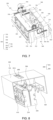
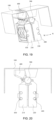
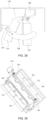
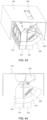
- the ice maker 1001 includes a base 100, a mold shell 400 (including a shell body 200 and a mold body 300), and a driving mechanism 500.
- the base 100 is configured to be connected with the ice making compartment. As shown in FIG. 4 , the base 100 includes a plurality of side plates.
- the plurality of side plates include an upper side plate 101, a left side plate 102, a right side plate 103, a front side plate 104, and a rear side plate.
- the left side plate 102 is opposite to the right side plate 103 in the left-right direction
- the front side plate 104 is opposite to the rear side plate in the front-rear direction
- the upper side plate 101 is located at an upper portion of the left side plate 102, the right side plate 103, the front side plate 104, and the rear side plate.
- the base 100 is not limited to be disposed in the ice making compartment in the front-rear direction as shown in FIG. 3 .
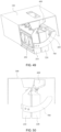
- the mold shell 400 includes a first sub-mold shell 401 and a second sub-mold shell 402 that may switch between a separated state and a closed state.
- the first sub-mold shell 401 and the second sub-mold shell 402 are closed to form a mold cavity
- a shape of the mold cavity is the shape of an ice cube
- the shape of the mold cavity may be adaptively designed according to the requirements of the user.
- the mold cavity may be designed to be of a sphere, a diamond-faced sphere, or a polyhedron.
- the first sub-mold shell 401 and the second sub-mold shell 402 are both movable, so that the first sub-mold shell 401 and the second sub-mold shell 402 may switch between the separated state and the closed state.
- the first sub-mold shell 401 and the second sub-mold shell 402 move away from each other; in the closed state, the first sub-mold shell 401 and the second sub-mold shell 402 move toward each other until they are closed.
- FIGS. 3, 4 , 8 , and 9 show that the first sub-mold shell 401 and the second sub-mold shell 402 are in a closed state
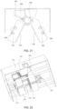
- FIGS. 5 and 10 show that the first sub-mold shell 401 and the second sub-mold shell 402 are in a separated state.
- the solution that the mold shell 400 includes a plurality of sub-mold shells is similar to a solution that the mold shell 400 includes the first sub-mold shell 401 and the second sub-mold shell 402, and the details will not be repeated herein.
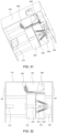
- the mold shell 400 includes a shell body 200 and a mold body 300.
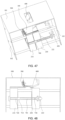
- the shell body 200 includes a first shell portion 210 and a second shell portion 220 that are disposed opposite to each other.
- the first shell portion 210 and the second shell portion 220 are disposed opposite to each other in the MN direction shown in FIG. 6 .
- the first shell portion 210 is located on the M side of the shell body 200
- the second shell portion 220 is located on the N side of the shell body 200
- the MN direction corresponds to the left-right direction of the shell body 200.
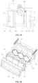
- An inner wall of the first shell portion 210 is provided with a first inner cavity 212A (referring to FIG. 6 ).
- An inner wall of the second shell portion 220 is provided with a second inner cavity, the second inner cavity is disposed opposite to the first inner cavity 212A, the second inner cavity and the first inner cavity 212A may be of a similar structure.
- the first shell portion 210 and the second shell portion 220 may switch between a closed state and a separated state. In the closed state, the first shell portion 210 and the second shell portion 220 are closed to form an inner cavity, thus the inner cavity is jointly defined by the first inner cavity 212A and the second inner cavity.
- the second mold portion 320 is connected with the second shell portion 220, so that the second mold portion 320 is fixed with respect to the second shell portion 220.
- the second mold portion 320 is disposed in the second inner cavity of the second shell portion 220
- the second mold portion 320 includes a second concave cavity 321 (referring to FIG. 6 )
- the second concave cavity 321 is disposed on a side of the second mold portion 320 facing the first mold portion 310.
- the first mold portion 310 and the second mold portion 320 may switch between a separated state and a closed state. In the closed state, the first mold portion 310 and the second mold portion 320 are closed to enclose the mold cavity, thus the mold cavity is jointly defined by the first concave cavity 311 and the second concave cavity 321.
- a first engaging portion 312 (referring to FIG. 13 ) is provided on an edge of the first concave cavity 311 of the first mold portion 310
- a second engaging portion 322 (referring to FIG. 6 ) is provided on an edge of the second concave cavity 321 of the second mold portion 320
- the second engaging portion 322 is configured to be matched with the first engaging portion.
- one of the first engaging portion 312 and the second engaging portion 322 includes a convex rib
- the other of the first engaging portion 312 and the second engaging portion 322 includes a groove
- the groove is matched with the convex rib.
- the first engaging portion 312 cooperates with the second engaging portion 322, it may be possible to improve the engaging cohesiveness between the first mold portion 310 and the second mold portion 320, and improve the aesthetics of the appearance of the ice cube, so that it may be possible to avoid a situation that the ice cube forms a convex edge at an engaging position between the first mold portion 310 and the second mold portion 320, which may cause the appearance of the ice cube to be irregular and affect the aesthetics of the appearance of the ice cube.
- At least one of the first mold portion 310 and the second mold portion 320 is configured to be deformed due to an external force.
- the first mold portion 310 and the second mold portion 320 are both food grade silicone members.
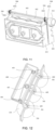
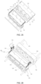
- the mold body 300 includes a plurality of water inlets 301 in communication with the mold cavity.
- the upper side plate 101 includes an opening 1011 (referring to FIG. 8 ) disposed at a position of the upper side plate 101 corresponding to the water inlet 301, and an external water pipe is connected with the water inlet 301 by passing through the opening 1011, so as to inject water into the mold cavity.
- the opening 1011 is formed as a rectangular through hole penetrating the upper side plate 101 in a thickness direction thereof.
- the mold body 300 includes a plurality of mold cavities.
- FIG. 12 shows an example in which the mold body 300 includes three mold cavities, and each mold cavity includes a water inlet 301.
- the ice maker 1001 includes a water tank 600.
- the water tank 600 is disposed above the shell body 200, the water tank 600 includes a plurality of water distribution pipes 602 and a plurality of water dividing ports 601 corresponding to the plurality of water inlets 301, and each water dividing port 601 is provided with a water distribution pipe 602 in communication with the water inlet 301.
- the water tank 600 is fixed to the base 100, and an opening 1011 (referring to FIG.
- the arrangement of the plurality of mold cavities may increase an amount of ice produced by the ice maker 1001 in a single time, and the water tank 600 provided with the plurality of water dividing ports 601 is beneficial to improve the efficiency of injecting water, thereby effectively increasing the ice making efficiency.
- the plurality of mold cavities are communicated with each other through a plurality of water holes 302.
- the mold body 300 in FIG. 13 includes three mold cavities, two adjacent mold cavities are communicated with each other through a water hole 302, so that water injected into a mold cavity may circulate in different mold cavities, thus water in the plurality of mold cavities tends to be average, which is beneficial to reduce weigh difference of the produced ice cubes.
- the water inlet 301 is formed as a closed shape.
- the structure defining the water inlet 301 is of an annular structure, and the water inlet 301 is defined on the inner side of the annular structure.
- FIG. 13 shows an example in which the water inlet 301 is in a shape of a funnel.
- the water inlet 301 is formed as a separated structure.
- a first concave cavity 311 is provided on a top portion of the first mold portion 310
- a second concave cavity 321 is provided on a top portion of the second mold portion 320.
- the first concave cavity 311 and the second concave cavity 321 are closed to form the water inlet 310.
- water may leak at the water inlet 301 of the separated structure during water injection. Since the amount of water injected in a single time is constant, if water leaks during water injection, the amount of water injected into the mold cavity will be reduced, and the weight of the produced ice cube will be less than the predetermined weight of the ice cube, which results in a decrease in integrity of the ice cube.
- the water inlet 301 is formed as an integral structure.
- the water inlet 301 is formed as a closed shape.
- the water inlet 301 is formed as an annular structure, and the water inlet 301 is defined on the inner side of the annular structure.
- FIG. 13 shows an example in which the water inlet 301 is in the shape of the funnel.
- the water inlet 301 is formed on the first mold portion 310 or the second mold portion 320.
- FIG. 13 shows an example in which the water inlet 301 is formed on the second mold portion 320, the water inlet 301 and the second mold portion 320 form a one-piece member.
- the water inlet 301 may also be formed on the first mold portion 310, the water inlet 301 and the first mold portion 310 form a one-piece member.
- the water inlet 301 is formed on the first mold portion 310 or the second mold portion 320, rather than being formed by combing two halves of the first mold portion 310 and the second mold portion 320, thus it may be possible to reduce the difficulty of the demolding process and improve the smoothness of the demolding process.
- the first shell portion 210 includes a first groove 211 located on a side of the first shell portion 210 proximate to the second shell portion 220, and the second shell portion 220 includes a second groove 221 located on a side of the second shell portion 220 proximate to the first shell portion 210.
- the first groove 211 and the second groove 221 are closed to form an avoidance opening 250 that encloses an outer circumference of the water inlet 301.
- the water inlet 301 is located within the avoidance opening 250.
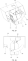
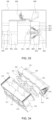
- the first sub-mold shell 401 includes a first shell portion 210 and a first mold portion 310.
- the ice maker 1001 includes at least one of a first push rod 410 or a second push rod 420.
- the first push rod 410 or the second push rod 420 is provided in a one-to-one correspondence with the mold cavity.
- the ice maker 1001 further includes a second push rod 420 located at a second predetermined distance from the second shell portion 220 away from the first shell portion 210.
- the second push rod 420 is fixed to the right side plate 103, the second shell portion 220 includes a second through hole 222 (referring to FIG. 4 ), the second through hole 222 is matched with the second push rod 420.
- the driving mechanism 500 is configured to drive the first sub-mold shell 401 and the second sub-mold shell 402 to move.
- the driving mechanism 500 is configured to drive the first shell portion 210 and the second shell portion 220 to move, so that the first shell portion 210 and the second shell portion 220 are separated or closed.
- the first mold portion 310 moves along with the first shell portion 210
- the second mold portion 320 moves along with the second shell portion 220.
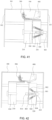
- FIG. 4 the first shell portion 210 and the second shell portion 220 are in a closed state; in FIG. 5 , the first shell portion 210 and the second shell portion 220 are in the separated state.
- the driving mechanism 500 drives the first shell portion 210 to move to a first predetermined position, the first push rod 410 passes through the first through hole 212 to push against the first mold portion 310, so that the first mold portion 310 is deformed due to stress.
- the driving mechanism 500 drives the second shell portion 220 to move to a second predetermined position, and the second push rod 420 passes through the second through hole 222 to push against the second mold portion 320, so that the second mold portion 320 is deformed due to stress.
- the driving mechanism 500 drives the first shell portion 210 to move toward the first push rod 410 to the first predetermined position, so that the first push rod 410 passes through the first through hole 212 to push against the first mold portion 310, and the first mold portion 310 is thus deformed due to stress, thereby demolding the ice cube in the first mold portion 310.
- the driving mechanism 500 drives the second shell portion 220 to move toward the second push rod 420 to the second predetermined position, so that the second push rod 420 passes through the second through hole 222 to push against the second mold portion 320, and the second mold portion 320 is thus deformed due to stress, thereby demolding the ice cube in the second mold portion 320.
- the ice cube in the first mold portion 310 or the second mold portion 320 may be pushed out, so that the ice cube may fallen into an ice storage box of the refrigerator 1 for access by the user, which has a good demolding effect.
- the refrigerator 1 includes an ice maker 1001, the ice maker 1001 includes an ice tray, the ice tray includes a first sub-mold shell 401 and a second sub-mold shell 402 that are both movable, so that the first sub-mold shell 401 and the second sub-mold shell 402 may switch between the separated state and the closed state.
- the ice maker 1001 is adapted to make specially shaped ice cubes that may be only formed by combing mold portions, such as spherical ice cubes or polyhedral ice cubes.
- first sub-mold shell 401 is movable, and the first push rod 410 is provided on a side of the first sub-mold shell 401 away from the second sub-mold shell 402.
- the second sub-mold shell 402 is movable, and the second push rod 420 is provided on a side of the second sub-mold shell 402 away from the first sub-mold shell 401.
- two sets of driving mechanisms 500 may be used to control the first shell portion 210 and the second shell portion 220, respectively.
- a same driving mechanism 500 may be used to control the opening-closing movement manner of the first shell portion 210 and the second shell portion 220.
- the opening-closing movement manner of the first shell portion 210 and the second shell portion 220 at least includes a translational manner and a rotational manner.
- a matched driving mechanism 500 is provided with respect to the translational manner or the rotational manner.
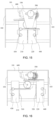
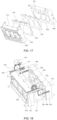
- the driving mechanism 500 includes a motor 510, a main rotating shaft 520, a first gear set 530, a second gear set 540, a first rack 550, a second rack 560, and a slide rod 550.
- the driving mechanism 500 includes two first racks 550 that are disposed on two sides of the top portion of the second shell portion 220 in a movement direction thereof (e.g., the movement direction is the left-right direction, and an arrangement direction of the two first racks 550 is the front-rear direction).
- the first rack 550 includes a first upper teeth portion 551 and a first lower teeth portion 552.
- the driving mechanism 500 includes two second racks 560 that are disposed on two sides of the middle portion of the first shell portion 210 in a movement direction thereof (e.g., the movement direction is the left-right direction, and an arrangement direction of the two second racks 560 is the front-rear direction).
- the second rack 560 includes a second upper teeth portion 561.
- the driving mechanism 500 includes four slide rods 570.
- the four slide rods 570 are inserted through four corners of the first shell portion 210 and the second shell portion 220.
- the motor 510 is connected with the main rotating shaft 520.
- a motor shaft of the motor 510 is connected with the main rotating shaft 520.
- the motor 510 is connected with the first gear set 530 through a transmission gear 511, and the first gear set 530 is connected with the main rotating shaft 520.
- the motor 510 may be fixed to the front side plate 104, as shown in FIG. 4 , the main rotating shaft 520 may be rotatably disposed on the front side plate 104 and the rear side plate through a bearing.
- the first gear set 530 includes at least two first sub-gears 531.
- the two first sub-gears 531 are disposed on two ends of the main rotating shaft 520, and each first sub-gear 531 is engaged with the first upper teeth portion 551 of the first rack 550.
- the second gear set 540 includes at least two second sub-gears 541 that are rotatably disposed on the front side plate 104 and the rear side plate through a bearing, respectively.
- the second upper teeth portion 561 of the second rack 560 is engaged with the first lower teeth portion 552 of the first rack 550 through the second gear set 540, so that the first shell portion 210 and the second shell portion 220 may translate in an opposite direction along the slide rod 570.
- the motor 510 drives the transmission gear 511 to rotate, the transmission gear 511 drives the first gear set 530 to rotate, the first gear set 530 drives the main rotating shaft 520 to rotate, the first gear set 530 drives the first upper teeth portion 551 to move, the first upper teeth portion 551 drives the first lower teeth portion 552 to move, the first lower teeth portion 552 drives the second gear set 540 to rotate, and the second gear set 540 drives the second rack 560 to move, so that the first shell portion 210 and the second shell portion 220 translate in the opposite direction along the slide rod 570.
- FIG. 4 shows that the driving mechanism 500 drives the first shell portion 210 and the second shell portion 220 to move to be in the closed state
- FIG. 5 shows that the driving mechanism 500 drives the first shell portion 210 and the second shell portion 220 to move to be in the separated state.
- a position of the first rack 550 and a position of the second rack 560 may be interchanged, other structures remain unchanged, and the operation principle is the same.
- the driving mechanism 500 includes a motor 510, a first rotating shaft 502, a second rotating shaft 503, and a rotating gear assembly 504.
- the first shell portion 210 is connected with the first rotating shaft 502, and the second shell portion 220 is connected with the second rotating shaft 503.
- the rotating gear assembly 504 includes four third sub-gears 5041. Two third sub-gears 5041 of the four third sub-gears 5041 are disposed on two ends of the first rotating shaft 502, and the other two third sub-gears 5041 of the four third sub-gears 5041 are disposed on two ends of the second rotating shaft 503. Two third sub-gears located on a same end of the first rotating shaft 502 and the second rotating shaft 503 are drivingly connected with each other.
- the motor 510 is connected with the first rotating shaft 502 or the second rotating shaft 503 ( FIG. 11 shows that the motor 510 is connected with the second rotating shaft 503), so that the first shell portion 210 and the second shell portion 220 may rotate in an opposite direction.
- FIGS. 8 and 9 show that the driving mechanism 500 drives the first shell portion 210 and the second shell portion 220 to move to be in the closed state, and
- FIG. 10 shows that the driving mechanism 500 drives the first shell portion 210 and the second shell portion 220 to move to be in the separated state.
- the ice maker 1001 may also not be provided with the first push rod 410 and the second push rod 420.
- the ice maker 1001 further includes at least one of a first heating mechanism 430 or a second heating mechanism 440.
- the first heating mechanism 430 or the second heating mechanism 440 is provided in a one-to-one correspondence with the mold cavity.
- the first heating mechanism 430 is disposed on a side of the first shell portion 210 away from the second shell portion 220.
- the first heating mechanism 430 is disposed on the M side of the first shell portion 210 in FIG. 19 .
- the second heating mechanism 440 is disposed on a side of the second shell portion 220 away from the first shell portion 210.
- the second heating mechanism 440 is disposed on the N side of the second shell portion 220 in FIG. 19 .
- the first heating mechanism 430 or the second heating mechanism 440 includes a U-shaped heating tube.
- the first heating mechanism 430 and the second heating mechanism 440 are started up to heat the first shell portion 210 and the second shell portion 220, respectively, and the heat is conducted to the first mold portion 310 and the second mold portion 320, so that the outer wall of the ice cube is melted, and the ice cube is thus separated from inner walls of the first mold portion 310 and the second mold portion 320.
- the driving mechanism 500 then drives the first shell portion 210 to be separated from the second shell portion 220, so that the ice cube falls into the ice storage box for access by the user.
- the mold shell 400 may be formed as a shell body 200 provided with the mold cavity.
- the mold body 300 may not be provided.
- the driving mechanism 500 is configured to drive the first sub-mold shell 401 to move, and the second sub-mold shell 402 is fixed.
- the driving mechanism 500 is configured to drive the first shell portion 210 to move, so that the first shell portion 210 is separated from or closed with the second shell portion 220 that is fixed, the first mold portion 310 moves along with the first shell portion 210, and the second mold portion 320 is fixed with respect to the second shell portion 220.
- the ice maker 1001 further includes a connecting rod assembly 700, the first push rod 410 is fixed, and the second push rod 420 is linked with the first shell portion 210 through the connecting rod assembly 700.
- FIG. 22 shows that the driving mechanism 500 drives the first shell portion 210 and the second shell portion 220 to be in a separated state
- FIG. 23 shows that the driving mechanism 500 drives the first shell portion 210 and the second shell portion 220 to be in a closed state.
- the driving mechanism 500 drives the first shell portion 210 to move to a predetermined position, the first push rod 410 passes through the first through hole 212 to push against the first mold portion 310, thus the first mold portion 310 is deformed due to stress. Since the second push rod 420 is linked with the first shell portion 210 through the connecting rod assembly 700, the second push rod 420 may be moved through the movement of the first shell portion 210, the second push rod 420 passes through the second through hole 222 to push against the second mold portion 320, thus the second mold portion 320 is deformed due to stress.
- the driving mechanism 500 drives the first shell portion 210 to move toward the first push rod 410 to the predetermined position, so that the first push rod 410 passes through the first through hole 212 to push against the first mold portion 310, and the first mold portion 310 is deformed due to stress, thus the ice cube in the first mold portion 310 is demolded.
- the first shell portion 210 drives the second push rod 420 to move toward the second through hole 222 through the connecting rod assembly 700, so that the second push rod 420 passes through the second through hole 222 to push against the second mold portion 320, and the second mold portion 320 is deformed due to stress, thus the ice cube in the second mold portion 320 is demolded.
- the driving mechanism in a case where the first shell portion 210 adopts a translational opening-closing movement, includes a motor 510, a main rotating shaft 520, a first gear set 530, a first rack 550, and a slide rod 570.
- a main difference between FIG. 26 and FIG. 7 is that the driving mechanism 500 shown in FIG. 26 does not include the second gear set 540 and the second rack 560, and the first rack 550 only includes the first upper teeth portion 551 and does not include the first lower teeth portion 552.
- the driving mechanism 500 includes two first racks 550 disposed on two sides of the top portion of the first shell portion 210 or the second shell portion 220 in the movement direction thereof (e.g., the movement direction is the left-right direction, and the arrangement direction of the two first racks 550 is the front-rear direction).
- the two first racks 550 are disposed on two sides of the top portion of the first shell portion 210 in the movement direction thereof.
- the motor 510 is connected with the main rotating shaft 520, and the first rack 550 is drivingly connected with the main rotating shaft 520 through the first gear set 530. Therefore, the motor 510 may drive the main rotating shaft 520 to rotate, the main rotating shaft 520 drives the gear set 530 to rotate, the first gear set 530 drives the first rack 550 to move, so that the first shell portion 210 translates along the slide rod 570.
- FIG. 23 shows that the driving mechanism 500 drives the first shell portion 210 to move to be in a closed state with the second shell portion 220
- FIG. 24 shows that the driving mechanism 500 drives the first shell portion 210 to move to be in a separated state with the second portion 220.
- the connecting rod assembly 700 includes a first connecting rod 710, a first buckle portion 720, and a second buckle portion 730.
- an extending direction of the first connecting rod 710 is substantially the same as the movement direction of the first shell portion 210.
- the first connecting rod 710 is in a shape of a straight rod extending in the MN direction.
- the first connecting rod 710 includes a first connecting rod body 7102, and a fixing hole 7101 penetrating the first connecting rod body 7102 in a thickness direction thereof.
- the fixing hole 7101 is provided on an end of the first connecting rod body 7102 adjacent to the first shell portion 210, and the other end of the first connecting rod body 7102 adjacent to second shell portion 220 is connected with the second push rod 420 (referring to FIG. 25 ).
- the first buckle portion 720 is matched with the fixing hole 7101, so that the first shell portion 210 is connected with the first connecting rod body 7102.
- the first buckle portion 720 may be formed as a convex structure that extends in a same direction as the first rack 550.
- the first connecting rod 710 further includes a first strip-shaped hole 701, the first strip-shaped hole 701 is formed as a through hole penetrating the first connecting rod body 7102 in the thickness direction thereof, and the first strip-shaped hole 701 is closer to the second push rod 420 than the fixing hole 7101. At least one of the front surface or the rear surface of the second shell portion 220 is provided with the second buckle portion 730, the second buckle portion 73 is inserted through the first strip-shaped hole 701, so that the first connecting rod body 7102 translates with respect to the second buckle portion 730.
- the front surface (or the rear surface) of the second shell portion 220 is provided with one or more second buckle portions 730, the second buckle portion 730 may be formed as a shaft-like structure that extends away from the front surface or the rear surface of the second shell portion 220.
- the extending direction of the second connecting rod 810 is substantially the same as the movement direction of the first shell portion 210.
- the second connecting rod 810 may be set as a strip-shaped and plate-like structure.
- the second connecting rod 810 includes a second connecting rod body 811, two connecting portions 812 arranged symmetrically with respect to an extending direction of the second connecting rod body 811, and an annular hole 801 penetrating the connecting portion 812 in the thickness direction thereof, an end of the spring 820 is connected with the annular hole 801.
- the protrusion 802 is disposed adjacent to the first shell portion 210.
- an included angle a of a predetermined angle between a connecting line of centers of the protrusion 802 and the annular hole 801 and a straight line where the second connecting rod body 811 is located, and the included angle ⁇ is in a range of 30° to 60° (e.g., 30°, 45°, or 60°).
- the second connecting rod 810 further includes a second strip-shaped hole 803 penetrating the second connecting rod body in a thickness thereof, the extending direction of the second strip-shaped hole 803 is substantively the same as the movement direction of the first shell portion 210.
- Two limiting protruding portions 804 are provided on the side surface of the second shell portion 220.
- a length of the second strip-shaped hole 803 is greater than a distance between the two limiting protruding portions 804, the second strip-shaped hole 803 may cooperate with the two limiting protruding portions 804 to limit a translation distance of the second connecting rod 810.
- the blocking portion 830 is disposed at a position of the first shell portion 210 corresponding to the second connecting rod 810, and is configured to abut against an end of the second connecting rod 810 proximate to the first shell portion 210 in a case where the first shell portion 210 and the second shell portion 220 are in a closed state, so that the spring 820 is in the stretched state.
- the blocking portion 830 moves along with the first shell portion 210 and releases the end of the second connecting rod 810 proximate to the first shell portion 210, so that the elastic assembly 800 is in the reset state.
- the driving mechanism 500 includes a motor 510 and a first rotating shaft 502.
- the first shell portion 210 is connected with the first rotating shaft 502, so that the first shell portion 210 moves synchronously with the first rotating shaft 502.
- the motor 510 is connected with the first rotating shaft 502, so that the motor 510 may drive the first rotating shaft 502 to rotate, and the first shell portion 210 may rotate in a predetermined direction through the rotation of the first rotating shaft 502. Referring to FIGS.
- the elastic assembly 800 includes a second connecting rod 810, a spring 820 and a blocking portion 830.
- the second connecting rod 810 in FIGS. 36 to 38 includes a first rod portion 8101 and a second rod portion 8102.
- An extending direction of the first rod portion 8101 is substantially the same as the movement direction of the first shell portion 210.
- the first rod portion 8101 is formed as an arc plate-like structure.
- An extending direction of the second rod portion 8102 is substantially perpendicular to the movement direction of the first shell portion 210.
- the second rod portion 8102 is formed as a strip-shaped and plate-like structure.
- the ice maker 1001 is provided with the fixing shaft 505, an end of the second rod portion 8102 proximate to the first rotating shaft 502 is rotatably connected with the fixing shaft 505, and an end of the second rod portion 8102 away from the first rotating shaft 502 is in fixed connection to an end of the first rod portion 8101 away from the first shell portion 210.
- the second rod portion 8102 is provided with an annular hole 801.
- the annular hole 801 is disposed in a substantially central portion of the second rod portion 8102.
- An end of the spring 820 is connected with the annular hole 801.
- the protrusion 802 is provided on a side surface of the second shell portion 220 opposite to the second connecting rod 810.
- the protrusion 802 is disposed on a substantially central portion of the side surface of the second shell portion 220.
- the other end of the spring 820 is connected with the protrusion 802.
- the end of the first rod portion 8101 away from the first shell portion 210 is also connected with the second push rod 420.
- the blocking portion 830 is disposed at a position of the first shell portion 210 corresponding to the first rod portion 8101, and is configured to abut against an end of the first rod portion 8101 proximate to the first shell portion 210 in a case where the first shell portion 210 and the second shell portion 220 are in a closed state, so that the spring 820 is in the stretched state.
- the ice maker 1001 is not provided with the first push rod 410.
- the ice maker 1001 further includes a first heating mechanism 430.
- the first heating mechanism 430 is disposed on a side of the first shell portion 210 away from the second shell portion 220.
- a main difference between FIGS. 40 and 31 , and FIGS. 43 and 36 is that the demolding of the first sub-mold shell 401 in FIGS. 40 and 43 is realized by melting the outer wall of the ice cube through the first heating mechanism 430, rather than by forcing the first mold portion 310 to be deformed due to stress by pushing the first push rod 410 against the first mold portion 310 through the first through hole 212.
- the ice maker 1001 further includes a first heating mechanism 430.
- a main difference between FIGS. 46 and 22 , and FIGS. 49 and 27 is that, the demolding of the first sub-mold shell 401 in FIGS. 46 and 49 is realized by melting the outer wall of the ice cube through the first heating mechanism 430, rather than by forcing the first mold portion 310 to be deformed due to stress by pushing the first push rod 410 against the first mold portion 310 through the first through hole 212.
- the connecting rod assembly 700 includes a third connecting rod 740.
- the second mold portion 320 is rotatably connected with the second shell portion 220, and the second mold portion 320 is rotatably connected with the first shell portion 210 through the third connecting rod 740.
- the second mold portion 320 is turned downwards to realize the demolding by rotating the second mold portion 320 with respect to the second shell portion 220.
- the bottom portion of the second mold portion 320 is rotatably connected with the bottom portion of the second shell portion 220.
- a first shaft portion 323 and a second shaft portion are provided on two sides of the bottom portion of the second mold portion 320, and a first bearing 222A and a second bearing 223 are correspondingly provided on two sides of the bottom portion of the second shell portion 220.
- the first shaft portion 323 is rotatably connected with the first bearing 222A
- the second shaft portion 324 is rotatably connected with the second bearing 223.
- the first bearing 222A is provided with a horizontal strip-shaped hole 2221, through which the first shaft portion 323 is rotatably connected with the first bearing 222A, so that the first shaft portion 323 may translate along the horizontal strip-shaped hole 2221.
- the ice maker 1001 further includes a guide rod 900.
- the top portion of the second shell portion 220 is rotatably connected with the top portion of the second mold portion 320 through the guide rod 900.
- a first limiting column 325 and a second limiting column 326 are provided on two sides of the top portion of the second mold portion 320 in the movement direction of the first shell portion 210.
- the guide rod 900 and the third connecting rod 740 are located on two sides of the mold shell, one of the guide rod 900 and the third connecting rod 740 is disposed on a side of the first shell portion 210 in the movement direction of the first shell portion 210, and the other of the guide rod 900 and the third connecting rod 740 is disposed on another side of the second shell portion 220 in the movement direction of the first shell portion 210.
- the guide rod 900 is provided with a third strip-shaped hole 901 that is arc-shaped, the first limiting column 325 is disposed in the third strip-shaped hole 901, so as to limit the turning angle of the second mold portion 320.
- a maximum turning angle of the second mold portion 320 under limitation of the guide rod 900 is a first inclination angle ⁇ .
- the third connecting rod 740 is provided with a fourth strip-shaped hole 702, the second limiting column 326 is clamped in the fourth strip-shaped hole 702, and the third connecting rod 740 is mainly configured to drive the second mold portion 320 to turn, and limit the turning angle of the second mold portion 320.
- a maximum turning angle of the second mold portion 320 under the driving of the third connecting rod 740 is a second inclination angle ⁇ .
- an absolute value of the difference between the first inclination angle ⁇ and the second inclination angle ⁇ is greater than 0 (the absolute value of the difference value is generally between 10° to 15°)
- the second mold portion 320 is twisted and deformed, so that the ice cube in the second mold portion 320 may be demolded.
- the ice maker 1001 only includes one heating mechanism. Referring to FIG. 64 , only the first shell portion 210 is provided with a first heating mechanism 430.
- the ice maker 1001 includes two heating mechanisms. Referring to FIG. 67 , the first shell portion 210 is provided with a first heating mechanism 430, and the second shell portion 220 is provided with a second heating mechanism 440.
- the second heating mechanism 440 is configured to start heating before the second mold portion 320 is turned, so that the outer wall of the ice cube proximate to the second shell portion 220 is melted, thus the ice cube is demolded more quickly when the second mold portion 320 is turned downwards.
Landscapes
- Engineering & Computer Science (AREA)
- Physics & Mathematics (AREA)
- Mechanical Engineering (AREA)
- Thermal Sciences (AREA)
- General Engineering & Computer Science (AREA)
- Production, Working, Storing, Or Distribution Of Ice (AREA)
- Moulds For Moulding Plastics Or The Like (AREA)
Applications Claiming Priority (12)
| Application Number | Priority Date | Filing Date | Title |
|---|---|---|---|
| CN202110599218.3A CN113237284B (zh) | 2021-05-28 | 2021-05-28 | 一种冰箱 |
| CN202110599421.0A CN113237285B (zh) | 2021-05-28 | 2021-05-28 | 一种冰箱 |
| CN202110598609.3A CN113237279B (zh) | 2021-05-28 | 2021-05-28 | 一种冰箱 |
| CN202110598608.9A CN113237278B (zh) | 2021-05-28 | 2021-05-28 | 一种冰箱 |
| CN202121189027.1U CN215176405U (zh) | 2021-05-28 | 2021-05-28 | 一种冰箱 |
| CN202110598792.7A CN113237281B (zh) | 2021-05-28 | 2021-05-28 | 一种冰箱 |
| CN202110598794.6A CN113237282B (zh) | 2021-05-28 | 2021-05-28 | 一种冰箱 |
| CN202121188879.9U CN215176404U (zh) | 2021-05-28 | 2021-05-28 | 一种冰箱 |
| CN202121190182.5U CN215176406U (zh) | 2021-05-28 | 2021-05-28 | 一种冰箱 |
| CN202110599135.4A CN113237283B (zh) | 2021-05-28 | 2021-05-28 | 一种冰箱 |
| EP22810192.9A EP4350262B1 (de) | 2021-05-28 | 2022-03-30 | Kühlschrank |
| PCT/CN2022/084198 WO2022247459A1 (zh) | 2021-05-28 | 2022-03-30 | 冰箱 |
Related Parent Applications (2)
| Application Number | Title | Priority Date | Filing Date |
|---|---|---|---|
| EP22810192.9A Division EP4350262B1 (de) | 2021-05-28 | 2022-03-30 | Kühlschrank |
| EP22810192.9A Division-Into EP4350262B1 (de) | 2021-05-28 | 2022-03-30 | Kühlschrank |
Publications (2)
| Publication Number | Publication Date |
|---|---|
| EP4534929A2 true EP4534929A2 (de) | 2025-04-09 |
| EP4534929A3 EP4534929A3 (de) | 2025-05-21 |
Family
ID=84229242
Family Applications (3)
| Application Number | Title | Priority Date | Filing Date |
|---|---|---|---|
| EP22810192.9A Active EP4350262B1 (de) | 2021-05-28 | 2022-03-30 | Kühlschrank |
| EP25159224.2A Pending EP4534929A3 (de) | 2021-05-28 | 2022-03-30 | Kühlschrank |
| EP25159227.5A Pending EP4538617A3 (de) | 2021-05-28 | 2022-03-30 | Kühlschrank |
Family Applications Before (1)
| Application Number | Title | Priority Date | Filing Date |
|---|---|---|---|
| EP22810192.9A Active EP4350262B1 (de) | 2021-05-28 | 2022-03-30 | Kühlschrank |
Family Applications After (1)
| Application Number | Title | Priority Date | Filing Date |
|---|---|---|---|
| EP25159227.5A Pending EP4538617A3 (de) | 2021-05-28 | 2022-03-30 | Kühlschrank |
Country Status (3)
| Country | Link |
|---|---|
| US (1) | US12510280B2 (de) |
| EP (3) | EP4350262B1 (de) |
| WO (1) | WO2022247459A1 (de) |
Families Citing this family (2)
| Publication number | Priority date | Publication date | Assignee | Title |
|---|---|---|---|---|
| AU2019355677B9 (en) * | 2018-10-02 | 2023-10-12 | Lg Electronics Inc. | Refrigerator |
| WO2024163881A1 (en) * | 2023-02-02 | 2024-08-08 | Abstract Ice, Inc. | Devices for shaping clear ice products and related methods |
Family Cites Families (48)
| Publication number | Priority date | Publication date | Assignee | Title |
|---|---|---|---|---|
| US3430452A (en) * | 1966-12-05 | 1969-03-04 | Manitowoc Co | Ice cube making apparatus |
| US4489567A (en) * | 1983-09-16 | 1984-12-25 | The Manitowoc Company, Inc. | Stackable water pressure ejection control ice cube maker |
| US6860111B2 (en) * | 2002-11-13 | 2005-03-01 | Hoshizaki Denki Kabushiki Kaisha | Automatic ice maker and its operating method |
| US7437885B2 (en) | 2004-10-26 | 2008-10-21 | Whirlpool Corporation | Water spillage management for in the door ice maker |
| JP2007240122A (ja) * | 2006-03-13 | 2007-09-20 | Japan Servo Co Ltd | 自動製氷装置 |
| KR100705182B1 (ko) * | 2006-05-29 | 2007-04-09 | 엘지전자 주식회사 | 냉장고용 아이스 트레이 어셈블리 |
| US8267493B2 (en) * | 2009-01-15 | 2012-09-18 | Lg Electronics Inc. | Refrigerator |
| CN101886863A (zh) | 2010-07-20 | 2010-11-17 | 合肥美的荣事达电冰箱有限公司 | 制冰机的制冰盘单元、制冰机及冰箱 |
| CN102135355A (zh) | 2011-05-05 | 2011-07-27 | 合肥美的荣事达电冰箱有限公司 | 手动制冰机及具有该手动制冰机的冰箱 |
| KR101890939B1 (ko) * | 2011-07-15 | 2018-08-23 | 엘지전자 주식회사 | 아이스 메이커 |
| KR101968563B1 (ko) | 2011-07-15 | 2019-08-20 | 엘지전자 주식회사 | 아이스 메이커 |
| CN102353193B (zh) * | 2011-09-02 | 2013-07-03 | 合肥美的荣事达电冰箱有限公司 | 制冰机和冰箱 |
| KR101850918B1 (ko) * | 2011-10-04 | 2018-05-30 | 엘지전자 주식회사 | 아이스 메이커 및 이를 이용한 얼음 제조 방법 |
| KR102023412B1 (ko) * | 2012-06-12 | 2019-09-20 | 엘지전자 주식회사 | 냉장고 |
| US8925335B2 (en) * | 2012-11-16 | 2015-01-06 | Whirlpool Corporation | Ice cube release and rapid freeze using fluid exchange apparatus and methods |
| US9696079B2 (en) | 2012-12-13 | 2017-07-04 | Whirlpool Corporation | Rotational ice maker |
| US9518770B2 (en) | 2012-12-13 | 2016-12-13 | Whirlpool Corporation | Multi-sheet spherical ice making |
| US9273891B2 (en) * | 2012-12-13 | 2016-03-01 | Whirlpool Corporation | Rotational ice maker |
| US9074802B2 (en) | 2012-12-13 | 2015-07-07 | Whirlpool Corporation | Clear ice hybrid mold |
| MX2015001519A (es) * | 2015-01-30 | 2016-07-29 | Mabe Sa De Cv | Dispositivo automatico de fabricacion de hielo. |
| KR102541390B1 (ko) | 2016-07-13 | 2023-06-09 | 삼성전자주식회사 | 제빙기 및 이를 갖는 냉장고 |
| CN107144065B (zh) | 2017-05-12 | 2020-08-28 | 青岛海尔股份有限公司 | 一种制冰模具及其制冰方法 |
| US10697684B2 (en) * | 2018-03-20 | 2020-06-30 | Bsh Home Appliances Corporation | Automatic ice-sphere-making system for refrigerator appliance |
| CN108895740B (zh) | 2018-04-25 | 2020-09-29 | 青岛海尔股份有限公司 | 制冰机及冰箱 |
| CN108981253A (zh) | 2018-06-14 | 2018-12-11 | 湖北美的电冰箱有限公司 | 一种顶出式制冰格结构及具有其的冰箱 |
| WO2020071787A1 (ko) | 2018-10-02 | 2020-04-09 | 엘지전자 주식회사 | 제빙기 및 이를 포함하는 냉장고 |
| EP3862668A4 (de) | 2018-10-02 | 2022-07-27 | LG Electronics Inc. | Eisbereiter und kühlschrank damit |
| US11920846B2 (en) | 2018-10-02 | 2024-03-05 | Lg Electronics Inc. | Refrigerator |
| WO2020071764A1 (ko) | 2018-10-02 | 2020-04-09 | 엘지전자 주식회사 | 제빙기 및 이를 포함하는 냉장고 |
| EP3653974B1 (de) | 2018-11-16 | 2025-09-03 | LG Electronics Inc. | Eisbereiter und kühlschrank |
| US11578904B2 (en) | 2018-11-16 | 2023-02-14 | Lg Electronics Inc. | Ice maker and refrigerator |
| US11313603B2 (en) * | 2018-11-16 | 2022-04-26 | Lg Electronics Inc. | Ice maker and refrigerator |
| EP4679013A2 (de) | 2018-11-16 | 2026-01-14 | LG Electronics Inc. | Eisbereiter und kühlschrank |
| KR102800294B1 (ko) | 2019-07-06 | 2025-04-29 | 엘지전자 주식회사 | 아이스 메이커 및 이를 포함하는 냉장고 |
| CN213119630U (zh) | 2020-06-09 | 2021-05-04 | 吴晓武 | 一种便于取冰的可拉伸冰格盒 |
| CN213040813U (zh) | 2020-08-13 | 2021-04-23 | 青岛海尔电冰箱有限公司 | 制冰装置 |
| TWI724966B (zh) | 2020-09-04 | 2021-04-11 | 台灣松下電器股份有限公司 | 自動製冰系統 |
| KR20220057215A (ko) | 2020-10-29 | 2022-05-09 | 삼성전자주식회사 | 냉장고 |
| CN113237278B (zh) * | 2021-05-28 | 2022-11-29 | 海信容声(广东)冰箱有限公司 | 一种冰箱 |
| CN113237283B (zh) * | 2021-05-28 | 2024-02-23 | 海信容声(广东)冰箱有限公司 | 一种冰箱 |
| CN113237285B (zh) * | 2021-05-28 | 2024-07-23 | 海信容声(广东)冰箱有限公司 | 一种冰箱 |
| CN215176405U (zh) * | 2021-05-28 | 2021-12-14 | 海信容声(广东)冰箱有限公司 | 一种冰箱 |
| CN116857886B (zh) | 2021-05-28 | 2025-10-21 | 海信容声(广东)冰箱有限公司 | 一种冰箱 |
| CN113237282B (zh) * | 2021-05-28 | 2024-04-23 | 海信容声(广东)冰箱有限公司 | 一种冰箱 |
| CN113237284B (zh) * | 2021-05-28 | 2023-12-22 | 海信容声(广东)冰箱有限公司 | 一种冰箱 |
| CN215176406U (zh) * | 2021-05-28 | 2021-12-14 | 海信容声(广东)冰箱有限公司 | 一种冰箱 |
| CN113237281B (zh) * | 2021-05-28 | 2022-11-29 | 海信容声(广东)冰箱有限公司 | 一种冰箱 |
| CN215176404U (zh) * | 2021-05-28 | 2021-12-14 | 海信容声(广东)冰箱有限公司 | 一种冰箱 |
-
2022
- 2022-03-30 EP EP22810192.9A patent/EP4350262B1/de active Active
- 2022-03-30 WO PCT/CN2022/084198 patent/WO2022247459A1/zh not_active Ceased
- 2022-03-30 EP EP25159224.2A patent/EP4534929A3/de active Pending
- 2022-03-30 EP EP25159227.5A patent/EP4538617A3/de active Pending
-
2023
- 2023-07-07 US US18/348,901 patent/US12510280B2/en active Active
Also Published As
| Publication number | Publication date |
|---|---|
| EP4534929A3 (de) | 2025-05-21 |
| US20230349614A1 (en) | 2023-11-02 |
| US12510280B2 (en) | 2025-12-30 |
| EP4538617A3 (de) | 2025-05-21 |
| WO2022247459A1 (zh) | 2022-12-01 |
| EP4350262A1 (de) | 2024-04-10 |
| EP4350262B1 (de) | 2025-10-29 |
| EP4538617A2 (de) | 2025-04-16 |
| EP4350262A4 (de) | 2024-09-18 |
Similar Documents
| Publication | Publication Date | Title |
|---|---|---|
| US12449178B2 (en) | Refrigerator | |
| US20230349613A1 (en) | Refrigerator | |
| US12510280B2 (en) | Refrigerator | |
| CN113237284B (zh) | 一种冰箱 | |
| US9234688B2 (en) | Ice maker | |
| EP2549208B1 (de) | Eismaschine | |
| EP3540339B1 (de) | Kühlschrank mit einem eisbereiter | |
| AU2009343710B2 (en) | Refrigerator having ice making device | |
| AU2021256018B2 (en) | Ice making assembly for receiving interchangeable mold assembly | |
| US20250123041A1 (en) | Revolving ice maker | |
| CN117120790A (zh) | 电器制冰组件 | |
| CN113237283B (zh) | 一种冰箱 | |
| KR101250157B1 (ko) | 댐퍼 장치 및 댐퍼 장치를 구비한 냉장고 | |
| CN113237281B (zh) | 一种冰箱 | |
| KR101575054B1 (ko) | 제빙장치가 구비된 냉장고 | |
| CN223319343U (zh) | 冰箱 | |
| CN220229689U (zh) | 冰箱 | |
| WO2024000702A1 (zh) | 冰箱 | |
| KR20230053108A (ko) | 제빙기 및 이를 포함하는 냉장고 | |
| KR20140123719A (ko) | 냉장고 | |
| KR19990035671U (ko) | 냉장고 선반용 도어 | |
| KR20150060643A (ko) | 제빙장치가 구비된 냉장고 |
Legal Events
| Date | Code | Title | Description |
|---|---|---|---|
| PUAI | Public reference made under article 153(3) epc to a published international application that has entered the european phase |
Free format text: ORIGINAL CODE: 0009012 |
|
| STAA | Information on the status of an ep patent application or granted ep patent |
Free format text: STATUS: REQUEST FOR EXAMINATION WAS MADE |
|
| 17P | Request for examination filed |
Effective date: 20250220 |
|
| AC | Divisional application: reference to earlier application |
Ref document number: 4350262 Country of ref document: EP Kind code of ref document: P |
|
| AK | Designated contracting states |
Kind code of ref document: A2 Designated state(s): AL AT BE BG CH CY CZ DE DK EE ES FI FR GB GR HR HU IE IS IT LI LT LU LV MC MK MT NL NO PL PT RO RS SE SI SK SM TR |
|
| REG | Reference to a national code |
Ref country code: DE Ref legal event code: R079 Free format text: PREVIOUS MAIN CLASS: F25C0001100000 Ipc: F25D0023120000 |
|
| PUAL | Search report despatched |
Free format text: ORIGINAL CODE: 0009013 |
|
| AK | Designated contracting states |
Kind code of ref document: A3 Designated state(s): AL AT BE BG CH CY CZ DE DK EE ES FI FR GB GR HR HU IE IS IT LI LT LU LV MC MK MT NL NO PL PT RO RS SE SI SK SM TR |
|
| RIC1 | Information provided on ipc code assigned before grant |
Ipc: F25C 1/10 20060101ALI20250417BHEP Ipc: F25D 23/12 20060101AFI20250417BHEP |