EP4534854A2 - Ventilsysteme - Google Patents
Ventilsysteme Download PDFInfo
- Publication number
- EP4534854A2 EP4534854A2 EP24204223.2A EP24204223A EP4534854A2 EP 4534854 A2 EP4534854 A2 EP 4534854A2 EP 24204223 A EP24204223 A EP 24204223A EP 4534854 A2 EP4534854 A2 EP 4534854A2
- Authority
- EP
- European Patent Office
- Prior art keywords
- centering
- land
- port
- valve
- housing
- Prior art date
- Legal status (The legal status is an assumption and is not a legal conclusion. Google has not performed a legal analysis and makes no representation as to the accuracy of the status listed.)
- Pending
Links
Images



Classifications
-
- F—MECHANICAL ENGINEERING; LIGHTING; HEATING; WEAPONS; BLASTING
- F15—FLUID-PRESSURE ACTUATORS; HYDRAULICS OR PNEUMATICS IN GENERAL
- F15B—SYSTEMS ACTING BY MEANS OF FLUIDS IN GENERAL; FLUID-PRESSURE ACTUATORS, e.g. SERVOMOTORS; DETAILS OF FLUID-PRESSURE SYSTEMS, NOT OTHERWISE PROVIDED FOR
- F15B13/00—Details of servomotor systems ; Valves for servomotor systems
- F15B13/02—Fluid distribution or supply devices characterised by their adaptation to the control of servomotors
- F15B13/04—Fluid distribution or supply devices characterised by their adaptation to the control of servomotors for use with a single servomotor
- F15B13/0401—Valve members; Fluid interconnections therefor
- F15B13/0402—Valve members; Fluid interconnections therefor for linearly sliding valves, e.g. spool valves
-
- F—MECHANICAL ENGINEERING; LIGHTING; HEATING; WEAPONS; BLASTING
- F15—FLUID-PRESSURE ACTUATORS; HYDRAULICS OR PNEUMATICS IN GENERAL
- F15B—SYSTEMS ACTING BY MEANS OF FLUIDS IN GENERAL; FLUID-PRESSURE ACTUATORS, e.g. SERVOMOTORS; DETAILS OF FLUID-PRESSURE SYSTEMS, NOT OTHERWISE PROVIDED FOR
- F15B13/00—Details of servomotor systems ; Valves for servomotor systems
- F15B13/02—Fluid distribution or supply devices characterised by their adaptation to the control of servomotors
- F15B13/04—Fluid distribution or supply devices characterised by their adaptation to the control of servomotors for use with a single servomotor
- F15B13/042—Fluid distribution or supply devices characterised by their adaptation to the control of servomotors for use with a single servomotor operated by fluid pressure
-
- F—MECHANICAL ENGINEERING; LIGHTING; HEATING; WEAPONS; BLASTING
- F15—FLUID-PRESSURE ACTUATORS; HYDRAULICS OR PNEUMATICS IN GENERAL
- F15B—SYSTEMS ACTING BY MEANS OF FLUIDS IN GENERAL; FLUID-PRESSURE ACTUATORS, e.g. SERVOMOTORS; DETAILS OF FLUID-PRESSURE SYSTEMS, NOT OTHERWISE PROVIDED FOR
- F15B13/00—Details of servomotor systems ; Valves for servomotor systems
- F15B13/02—Fluid distribution or supply devices characterised by their adaptation to the control of servomotors
- F15B13/04—Fluid distribution or supply devices characterised by their adaptation to the control of servomotors for use with a single servomotor
- F15B13/042—Fluid distribution or supply devices characterised by their adaptation to the control of servomotors for use with a single servomotor operated by fluid pressure
- F15B13/043—Fluid distribution or supply devices characterised by their adaptation to the control of servomotors for use with a single servomotor operated by fluid pressure with electrically-controlled pilot valves
- F15B13/0431—Fluid distribution or supply devices characterised by their adaptation to the control of servomotors for use with a single servomotor operated by fluid pressure with electrically-controlled pilot valves the electrical control resulting in an on-off function
-
- F—MECHANICAL ENGINEERING; LIGHTING; HEATING; WEAPONS; BLASTING
- F16—ENGINEERING ELEMENTS AND UNITS; GENERAL MEASURES FOR PRODUCING AND MAINTAINING EFFECTIVE FUNCTIONING OF MACHINES OR INSTALLATIONS; THERMAL INSULATION IN GENERAL
- F16K—VALVES; TAPS; COCKS; ACTUATING-FLOATS; DEVICES FOR VENTING OR AERATING
- F16K11/00—Multiple-way valves, e.g. mixing valves; Pipe fittings incorporating such valves
- F16K11/02—Multiple-way valves, e.g. mixing valves; Pipe fittings incorporating such valves with all movable sealing faces moving as one unit
- F16K11/06—Multiple-way valves, e.g. mixing valves; Pipe fittings incorporating such valves with all movable sealing faces moving as one unit comprising only sliding valves, i.e. sliding closure elements
- F16K11/065—Multiple-way valves, e.g. mixing valves; Pipe fittings incorporating such valves with all movable sealing faces moving as one unit comprising only sliding valves, i.e. sliding closure elements with linearly sliding closure members
- F16K11/07—Multiple-way valves, e.g. mixing valves; Pipe fittings incorporating such valves with all movable sealing faces moving as one unit comprising only sliding valves, i.e. sliding closure elements with linearly sliding closure members with cylindrical slides
-
- F—MECHANICAL ENGINEERING; LIGHTING; HEATING; WEAPONS; BLASTING
- F16—ENGINEERING ELEMENTS AND UNITS; GENERAL MEASURES FOR PRODUCING AND MAINTAINING EFFECTIVE FUNCTIONING OF MACHINES OR INSTALLATIONS; THERMAL INSULATION IN GENERAL
- F16K—VALVES; TAPS; COCKS; ACTUATING-FLOATS; DEVICES FOR VENTING OR AERATING
- F16K11/00—Multiple-way valves, e.g. mixing valves; Pipe fittings incorporating such valves
- F16K11/02—Multiple-way valves, e.g. mixing valves; Pipe fittings incorporating such valves with all movable sealing faces moving as one unit
- F16K11/06—Multiple-way valves, e.g. mixing valves; Pipe fittings incorporating such valves with all movable sealing faces moving as one unit comprising only sliding valves, i.e. sliding closure elements
- F16K11/065—Multiple-way valves, e.g. mixing valves; Pipe fittings incorporating such valves with all movable sealing faces moving as one unit comprising only sliding valves, i.e. sliding closure elements with linearly sliding closure members
- F16K11/07—Multiple-way valves, e.g. mixing valves; Pipe fittings incorporating such valves with all movable sealing faces moving as one unit comprising only sliding valves, i.e. sliding closure elements with linearly sliding closure members with cylindrical slides
- F16K11/0708—Multiple-way valves, e.g. mixing valves; Pipe fittings incorporating such valves with all movable sealing faces moving as one unit comprising only sliding valves, i.e. sliding closure elements with linearly sliding closure members with cylindrical slides comprising means to avoid jamming of the slide or means to modify the flow
-
- F—MECHANICAL ENGINEERING; LIGHTING; HEATING; WEAPONS; BLASTING
- F15—FLUID-PRESSURE ACTUATORS; HYDRAULICS OR PNEUMATICS IN GENERAL
- F15B—SYSTEMS ACTING BY MEANS OF FLUIDS IN GENERAL; FLUID-PRESSURE ACTUATORS, e.g. SERVOMOTORS; DETAILS OF FLUID-PRESSURE SYSTEMS, NOT OTHERWISE PROVIDED FOR
- F15B13/00—Details of servomotor systems ; Valves for servomotor systems
- F15B13/02—Fluid distribution or supply devices characterised by their adaptation to the control of servomotors
- F15B13/04—Fluid distribution or supply devices characterised by their adaptation to the control of servomotors for use with a single servomotor
- F15B13/0401—Valve members; Fluid interconnections therefor
- F15B2013/0412—Valve members; Fluid interconnections therefor with three positions
-
- F—MECHANICAL ENGINEERING; LIGHTING; HEATING; WEAPONS; BLASTING
- F15—FLUID-PRESSURE ACTUATORS; HYDRAULICS OR PNEUMATICS IN GENERAL
- F15B—SYSTEMS ACTING BY MEANS OF FLUIDS IN GENERAL; FLUID-PRESSURE ACTUATORS, e.g. SERVOMOTORS; DETAILS OF FLUID-PRESSURE SYSTEMS, NOT OTHERWISE PROVIDED FOR
- F15B2211/00—Circuits for servomotor systems
- F15B2211/30—Directional control
- F15B2211/305—Directional control characterised by the type of valves
- F15B2211/3056—Assemblies of multiple valves
- F15B2211/30585—Assemblies of multiple valves having a single valve for multiple output members
-
- F—MECHANICAL ENGINEERING; LIGHTING; HEATING; WEAPONS; BLASTING
- F15—FLUID-PRESSURE ACTUATORS; HYDRAULICS OR PNEUMATICS IN GENERAL
- F15B—SYSTEMS ACTING BY MEANS OF FLUIDS IN GENERAL; FLUID-PRESSURE ACTUATORS, e.g. SERVOMOTORS; DETAILS OF FLUID-PRESSURE SYSTEMS, NOT OTHERWISE PROVIDED FOR
- F15B2211/00—Circuits for servomotor systems
- F15B2211/30—Directional control
- F15B2211/315—Directional control characterised by the connections of the valve or valves in the circuit
- F15B2211/31523—Directional control characterised by the connections of the valve or valves in the circuit being connected to a pressure source and an output member
- F15B2211/31541—Directional control characterised by the connections of the valve or valves in the circuit being connected to a pressure source and an output member having a single pressure source and multiple output members
-
- F—MECHANICAL ENGINEERING; LIGHTING; HEATING; WEAPONS; BLASTING
- F15—FLUID-PRESSURE ACTUATORS; HYDRAULICS OR PNEUMATICS IN GENERAL
- F15B—SYSTEMS ACTING BY MEANS OF FLUIDS IN GENERAL; FLUID-PRESSURE ACTUATORS, e.g. SERVOMOTORS; DETAILS OF FLUID-PRESSURE SYSTEMS, NOT OTHERWISE PROVIDED FOR
- F15B2211/00—Circuits for servomotor systems
- F15B2211/30—Directional control
- F15B2211/32—Directional control characterised by the type of actuation
- F15B2211/329—Directional control characterised by the type of actuation actuated by fluid pressure
Definitions
- This disclosure relates to valve systems.
- Certain transfer valves have used springs or modulating electro-mechanical interconnect devices (EMIDs) to accomplish a center position with no hard stop. Such devices increase the weight and complexity of valve systems.
- EMIDs electro-mechanical interconnect devices
- the hydraulic centering system can be configured to maintain the transfer valve to the first position.
- the hydraulic centering system can be configured to hydraulically bias the transfer valve in opposite directions to maintain the transfer valve in the first position.
- the transfer valve can include a housing and a spool positioned within the housing.
- the spool can be configured to move within the housing between the first position, the second position, and the third position.
- the hydraulic centering system can further include a first high pressure centering port defined through the housing, a second high pressure centering port defined through the housing, and at least one low pressure centering port defined through the housing between the first high pressure centering port and the second high pressure centering port.
- the first high pressure centering port can be configured to be in fluid communication with a first centering control pressure line
- the second high pressure centering port can be configured to be in fluid communication with a second centering pressure control line.
- the spool can further include a centering land extending radially outwardly from a shaft of the spool.
- the hydraulic centering system land can partially define a first cavity on a first side of the centering land which is in fluid communication with the first high pressure centering port, and a second cavity on a second side of the centering land in fluid communication with the second high pressure centering port.
- the centering land can be configured to block the at least one low pressure centering port in the first position.
- the system further includes a first land extending radially from the shaft of the spool to slidably seal to the housing and a second land extending radially from the shaft of the spool to slidably seal to the housing.
- the centering land can be positioned between the first land and the second land.
- the first cavity can be at least partially defined between the first land and the centering land and the second cavity can be at least partially defined between the centering land and the second land.
- the first land, the second land, and centering land can each include a respective seal configured to seal to an inner diameter of the housing.
- the at least one low pressure centering port can include a first low pressure centering port and a second low pressure centering port positioned between the first high pressure centering port and the second high pressure centering port.
- the first low pressure centering port and the second low pressure centering port can be configured to be blocked by the centering land in the first position.
- the first position can be between the second position and the third position.
- the first position can be centered between the second position and the third position.
- a pressure differential across the transfer valve can be within a first mode threshold such that the centering system hydraulically biases the transfer valve in the first position or about the first position.
- the pressure differential across the transfer valve can be outside the first mode threshold such that the centering system does not maintain the transfer valve in the first position and the transfer valve is moved to the second position.
- the pressure differential across the transfer valve can be outside the first mode threshold such that the centering system does not maintain the transfer valve in the first position and the transfer valve is moved to the third position.
- a valve can include a housing, a spool, and a hydraulic centering feature.
- the housing can include a first high pressure centering port, a second high pressure centering port, and at least one low pressure centering port between the first high pressure centering port and the second high pressure centering port.
- the spool can include a shaft and can be configured to move within the housing between a first position, a second position, and a third position.
- the hydraulic centering land can be operatively associated with or forming part of the spool and can extend radially outward relative to the shaft of the spool.
- the hydraulic centering land can be configured to hydraulically bias the spool in the first position.
- the first position can be between the second position and the third position.
- the centering land can be configured to be between the first high pressure centering port and the second high pressure centering port.
- the centering land can partially define a first cavity on a first side of the centering land which is in fluid communication with the first high pressure centering port, and a second cavity on a second side of the centering land in fluid communication with the second high pressure centering port.
- the centering land can be configured to block the at least one low pressure centering port in the first position.
- the valve can further include a seal on an outer surface of the centering land.
- the seal can seal against the housing to prevent leakage to the at least one low pressure centering port.
- a valve can include a housing, a spool, and one or more hydraulic centering features.
- the spool can be configured to move within the housing between a first position, a second position, and a third position.
- the one or more hydraulic centering features can be associated with the housing and/or the spool and configured to hydraulically bias the spool in the first position.
- the first position can be between the second position and the third position.
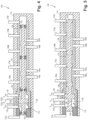
- FIG. 1 an illustrative view of an embodiment of a system in accordance the disclosure is shown in Fig. 1 and is designated generally by reference character 100.
- FIG. 2-6 Other embodiments and/or aspects of this disclosure are shown in Figs. 2-6 .
- a system 100 can include a first controllable valve 102 configured to output a control pressure on one or more first pressure control lines 104a, 104b, a second controllable valve 106 configured to output a control pressure on one or more second pressure control lines 108a, 108b, a transfer valve 110 in fluid communication with the first controllable valve 102 and the second controllable valve 106, and a hydraulic centering system 112 operatively associated with and/or forming part of the transfer valve 110.
- the transfer valve 110 can be configured to move between a first position (e.g. as shown in Figs. 1-4 ), a second position (e.g., as shown in Fig.
- the hydraulic centering system 112 can be configured to hydraulically bias the transfer valve 110 in the first position (e.g., in a first mode of operation where both controllable valves 102, 106 are functioning properly).
- the hydraulic centering system 112 can be configured to maintain the transfer valve 110 to the first position.
- the hydraulic centering system 112 can be configured to hydraulically bias the transfer valve 110 in opposite directions to maintain the transfer valve 110 in the first position.
- a transfer valve 210 can include a housing 114 and a spool 116 positioned within the housing 114.
- the spool 116 can be configured to move within the housing 114 between the first position (e.g., as shown in Fig. 2 ), the second position (e.g., as shown in Fig. 5 ), and the third position (e.g., as shown in Fig. 6 ).
- the hydraulic centering system 112 can further include a first high pressure centering port 118 defined through the housing 114, a second high pressure centering port 120 defined through the housing 114, and at least one low pressure centering port 122 defined through the housing 114 between the first high pressure centering port 118 and the second high pressure centering port 120.
- the first high pressure centering port 118 can be configured to be in fluid communication with a first centering control pressure line 124 (e.g., as shown in Fig. 1 )
- the second high pressure centering port 120 can be configured to be in fluid communication with a second centering pressure control line 126 (e.g., as shown in Fig. 1 ).
- Low pressure centering port 122 can be configured to be in fluid communication with low pressure line 127 (e.g., as shown in Fig. 1 ) such that when the valve 110 moves to either side, one of the high pressure ports 118, 120 begins to flow into the low pressure line 127 through the low pressure port 122, reducing the pressure and centering the valve 110.
- low pressure line 127 e.g., as shown in Fig. 1
- the spool 116 can further include a centering land 128 extending radially outwardly from a shaft 130 of the spool 116.
- the spool 116 can be configured to at least partially seal to an inner dimension 115 of the housing 114 to reduce or prevent leakage.
- the hydraulic centering system 112 land can partially define a first cavity 132 on a first side of the centering land 128 which is in fluid communication with the first high pressure centering port 118, and a second cavity 134 on a second side of the centering land 128 in fluid communication with the second high pressure centering port 120.
- the spool 116 can include a first land 136 extending radially from the shaft 130 of the spool 116 to slidably seal to the housing 114 and a second land 140 extending radially from the shaft 130 of the spool 116 to slidably seal to the housing 114.
- the centering land 128 can be positioned between the first land 136 and the second land 140.
- the first cavity 132 can be partially defined by a first land 136, a valve sleeve 138, and the shaft 130 of the spool 116.
- the second cavity 134 can be partially defined by a second land 140, the valve sleeve 138, and the shaft 130 of the spool 116.
- the centering land 128 can be configured to block the at least one low pressure centering port 122 in the first position.
- the centering land has a wider outer dimension (e.g., diameter) than the other lands (e.g., first and second lands and all other lands can have the same outer dimension)
- the first cavity 132 can be at least partially defined between the first land 136 and the centering land 128 and the second cavity 134 can be at least partially defined between the centering land 128 and the second land 140.
- the first land 136, the second land 140, and centering land 128 can each include a respective seal 142a-c configured to seal to an inner dimension 115 of the housing 114.
- a transfer valve 310 can include a centering land 328 that does not include any seals (e.g., as long as a desired sealing effect is achieved for the proper function of the transfer valve 210 and/or the centering system 112). As shown, the transfer valve 310 can be otherwise the same or similar to the transfer valve 210 of Fig. 2 .
- the pressure differential across the transfer valve 110 can be outside the first mode threshold such that the centering system 112 does not maintain the transfer valve 110 in the first position and the transfer valve is moved to the second position.
- a third mode e.g., as shown in Fig. 6
- the pressure differential across the transfer valve 110 can be outside the first mode threshold such that the centering system 112 does not maintain the transfer valve 110 in the first position and the transfer valve 110 is moved to the third position.
- certain embodiments can be or include a transfer valve.
- the transfer valve 210 can include a housing 114, a spool 116, and a hydraulic centering land 128.
- the housing 114 can include a first high pressure centering port 118, a second high pressure centering port 120, and at least one low pressure centering port 122 between the first high pressure centering port 118 and the second high pressure centering port 120.
- the spool 116 can include a shaft 130 and can be configured to move within the housing 114 between a first position, a second position, and a third position.
- the hydraulic centering land 128 can be operatively associated with or forming part of the spool 116 and can extend radially outward relative to the shaft 130 of the spool 116.
- the hydraulic centering land 128 can be configured to maintain the spool 116 in the first position.
- the first position can be between the second position and the third position.
- the at least one low pressure centering port 122 includes a first low pressure centering port 422a and a second low pressure centering port 422b between the first high pressure centering port 118 and the second high pressure centering port 120, wherein the first low pressure centering port 122a and the second low pressure centering port 122b are configured to be blocked by the spool 116 in the first position.
- the centering land 128 can be configured to be between the first high pressure centering port 118 and the second high pressure centering port 120.
- the centering land 128 can partially define a first cavity 132 on a first side of the centering land 128 which is in fluid communication with the first high pressure centering port 118, and a second cavity 134 on a second side of the centering land 128 in fluid communication with the second high pressure centering port 120.
- the centering land 128 can be configured to block the at least one low pressure centering port 122 in the first position.
- the centering land 128 can be configured such that if the spool 116 moves toward the second position (e.g., as shown in Fig. 5 ), the at least one low pressure centering port 122 is progressively exposed to the first cavity 132 to cause a reduction in pressure in the first cavity 132 to the second cavity 134, resulting in a restorative force acting on the centering system 112 toward the first position.
- the centering land 128 can be configured such that if the spool 116 moves toward the third position (e.g., as shown in Fig.
- the at least one low pressure centering port 122 is progressively exposed to the second cavity 134 to cause a reduction in pressure in the second cavity 134 to the first cavity 132, resulting in the restorative force acting on the centering system 112 toward the first position.
- valve 110 can further include a seal 142 on an outer surface of the centering land 128.
- the seal can seal against the housing to prevent leakage to the at least one low pressure centering port 122.
- One or more embodiments of a transfer valve 210,310, 410, 510 can include any other suitable features disclosed herein, e.g., described above.
- a valve 110 can include a housing 114, a spool 116, and one or more hydraulic centering features (e.g., one or more ports and/or lands, e.g., as described above, configured to provide hydraulic centering).
- the spool 116 can be configured to move within the housing 114 between a first position, a second position, and a third position.
- the one or more hydraulic centering features can be associated with the housing 114 and/or the spool 116 and configured to hydraulically bias the spool toward the first portion to hydraulically bias the spool in the first position.
- the first position can be between the second position and the third position. No other structure (e.g., springs, etc.) are required for centering the transfer valve 110. Certain embodiments, e.g., as shown only include the hydraulic centering system 112.
- the transfer valve 110 can be configured to fluidly communicate the one or more first pressure control lines 104a, 104b to a first functional system 144 and the one or more second pressure control lines 108a, 108b to a second functional system 146 in the first position (e.g., as shown).
- the transfer valve 110 can be configured to be controlled by a transfer control system 148 (e.g., as shown in Fig. 1 ), which includes at least one transfer control valve 150, such that the at least one transfer control valve outputs a transfer control pressure on one or more third pressure control lines 153, wherein the at least one transfer control valve 150 is in fluid communication with the transfer valve 110 via the one or more third pressure control lines 153 to control a position of the transfer valve 110 via the transfer control pressure on the one or more third pressure control lines 153.
- the transfer control pressure on the one or more third pressure control lines 153 is higher than a centering pressure along one or more center pressure control lines 154.
- the transfer control system 148 can further include a controller (not shown) configured to control the at least one transfer control valve 150 to change the position of the transfer valve 110.
- the first controllable valve 102 controls the first functional system 144 and the second controllable valve 106 controls the second functional system 146.
- the controller in a second mode, can be configured to control the at least one transfer control valve 150 to position the transfer valve 510 in the second position, wherein the transfer valve 510 is configured to fluidly communicate the one or more first pressure control lines 104a, 104b to the first functional system 144 and the second functional system in the second position 146 (e.g. communication along the one or more second pressure control lines 108a, 108b is blocked).
- the first controllable valve 103 controls both the first and second functional systems 144, 146.
- the first and second controllable valves 102, 106 can be EHSVs.
- the first and second functional systems 144, 146 can include a plurality of actuators.
- the at least one transfer control valve 150 includes a first solenoid 153a and a second solenoid 153b.
- the one or more third pressure control lines 153 include a first solenoid control line 153a and a second solenoid control line 153b, wherein the first solenoid control line 153a is connected to a first portion of the transfer valve 156 and the second solenoid control line 153b is connected to a second portion of the transfer valve 158 to control a pressure differential across the transfer valve 110 to control the position of the transfer valve 110 between the second and third positions.
- the housing 114 can include one or more first functional system ports 160a, 160b configured to fluidly connect to one or more first functional system lines 162a, 162b (e.g., as shown in Fig. 1 ).
- the housing 114 can include one or more second functional system ports 164a, 164b configured to fluidly connect to one or more second functional system lines 166a, 166b (e.g., as shown in Fig. 1 ).
- the housing 114 can include one or more the first controllable valve ports 168a, 168b configured to fluidly connect to the one or more first pressure control lines 104a, 104b (e.g., as shown in Fig. 1 ).
- the housing 114 can include one or more second controllable valve ports 170a, 170b configured to fluidly connect to the one or more second pressure control lines 108a, 108b (e.g., as shown in Fig. 1 ).
- the housing 114 can include one or more transfer control ports 172a, 172b configured to connect to the one or more third pressure control lines 153a, 153b to be in fluid communication with the transfer control valve 110.
- the spool 116 can be configured to move within the housing 114 between the first position, the second position, and third position to selectively communicate the one or more first functional system ports 160a, 160b and the one or more second functional system ports 164a, 164b with the one or more first controllable valve ports 168a, 168b or the one or more second controllable valve ports 170a, 170b as a function of a pressure differential between the one or more transfer control ports 172a, 172b.
- the spool 116 in the first position (e.g., as shown in Figs. 1-4 ), can be configured to fluidly communicate the one or more first functional system ports 160a, 160b to the one or more the first controllable valve ports 168a, 168b and the one or more second functional system ports 164a, 164b to the one or more the second controllable valve ports 170a, 170b, and can be configured to block communication between the one or more first functional system ports 160a, 160b from the one or more second controllable valve ports 170a, 170b and the one or more second functional system ports 164a, 164b from the one or more first controllable valve ports 168a, 168b.
- the spool 116 in the second position, can be configured to fluidly communicate the one or more first functional system ports 160a, 160b to the one or more the first controllable valve ports 168a, 168b and the one or more first functional system ports 160a, 160b to the one or more the second controllable valve ports 170a, 170b, and can be configured to block communication between the one or more second functional system ports 164a, 164b from the one or more second controllable valve ports 170a, 170b and the one or more second functional system ports 164a, 164b from the one or more first controllable valve ports 168a, 168b.
- the spool 116 in the third position, can be configured to fluidly communicate the one or more second functional system ports 164a, 164b to the one or more the first controllable valve ports 168a, 168b and the one or more second functional system ports 164a, 164b to the one or more the second controllable valve ports 170a, 170b, and can be configured to block communication between the one or more first functional system ports 160a, 160b from the one or more first controllable valve ports 168a, 168b and the one or more first functional system ports 160a, 160b from the one or more second controllable valve ports 170a, 170b.
- the transfer valve is centered in the first position (e.g., normal position) by the hydraulically modulating centering system. If the transfer valve moves away from the center (e.g., first position), the modulating pressure drops the pressure in one or more cavities as described (e.g., first and second cavities) above and provides a centering load on the transfer valve.
- the orifice e.g., orifices 135a, 135b in Fig. 1 ) sizes and tolerances are arranged such that the hydraulically modulated centered position is within a small linear length.
- the centering system operates on a smaller area of the spool than the primary diameter of the valve so that in the event of a failure of either of the first and second controllable valves, the transfer control system can command the transfer valve to move to the second or third position, over- riding the centering system and providing backup to the system as described in detail above.
- the centering system provides a weight benefit as compared to traditional systems which require springs or a modulating electro-mechanical interconnect devices (EMIDs) to accomplish a center position with no hard stop.
- EMIDs modulating electro-mechanical interconnect devices
- the system as described above reduces the need for active control of the transfer valve and increases force margins for the centering system.
- Embodiments can provide for valve systems with reduced weight, reduced need for active control of the transfer valve, and increased force margins for the centering system.
- Embodiments can provide for controlling two systems (e.g., 144, 146) with one control system rather than two control systems for each of the systems.
- Embodiments can include any suitable computer hardware and/or software module(s) to perform any suitable function (e.g., as disclosed herein).
- any suitable computer hardware and/or software module(s) to perform any suitable function (e.g., as disclosed herein).
- aspects of the present disclosure may be embodied as a system, method or computer program product.
- the computer readable medium may be a computer readable signal medium or a computer readable storage medium.
- a computer readable storage medium may be, for example, but not limited to, an electronic, magnetic, optical, electromagnetic, infrared, or semiconductor system, apparatus, or device, or any suitable combination of the foregoing.
- a computer readable storage medium may be any tangible medium that can contain, or store a program for use by or in connection with an instruction execution system, apparatus, or device.
- a computer readable signal medium may include a propagated data signal with computer readable program code embodied therein, for example, in baseband or as part of a carrier wave. Such a propagated signal may take any of a variety of forms, including, but not limited to, electro-magnetic, optical, or any suitable combination thereof.
- a computer readable signal medium may be any computer readable medium that is not a computer readable storage medium and that can communicate, propagate, or transport a program for use by or in connection with an instruction execution system, apparatus, or device.
- Program code embodied on a computer readable medium may be transmitted using any appropriate medium, including but not limited to wireless, wireline, optical fiber cable, RF, etc., or any suitable combination of the foregoing.
- Computer program code for carrying out operations for aspects of this disclosure may be written in any combination of one or more programming languages, including an object oriented programming language such as Java, Smalltalk, C++ or the like and conventional procedural programming languages, such as the "C" programming language or similar programming languages.
- the program code may execute entirely on the user's computer, partly on the user's computer, as a stand-alone software package, partly on the user's computer and partly on a remote computer or entirely on the remote computer or server.
- the remote computer may be connected to the user's computer through any type of network, including a local area network (LAN) or a wide area network (WAN), or the connection may be made to an external computer (for example, through the Internet using an Internet Service Provider).
- LAN local area network
- WAN wide area network
- Internet Service Provider for example, AT&T, MCI, Sprint, EarthLink, MSN, GTE, etc.
- These computer program instructions may also be stored in a computer readable medium that can direct a computer, other programmable data processing apparatus, or other devices to function in a particular manner, such that the instructions stored in the computer readable medium produce an article of manufacture including instructions which implement the function/act specified in the flowchart and/or block diagram block or blocks.
- any numerical values disclosed herein can be exact values or can be values within a range. Further, any terms of approximation (e.g., “about”, “approximately”, “around”) used in this disclosure can mean the stated value within a range. For example, in certain embodiments, the range can be within (plus or minus) 20%, or within 10%, or within 5%, or within 2%, or within any other suitable percentage or number as appreciated by those having ordinary skill in the art (e.g., for known tolerance limits or error ranges).
Landscapes
- Engineering & Computer Science (AREA)
- General Engineering & Computer Science (AREA)
- Mechanical Engineering (AREA)
- Physics & Mathematics (AREA)
- Fluid Mechanics (AREA)
- Multiple-Way Valves (AREA)
- Vehicle Body Suspensions (AREA)
- Fluid-Pressure Circuits (AREA)
Applications Claiming Priority (1)
| Application Number | Priority Date | Filing Date | Title |
|---|---|---|---|
| US18/376,103 US12429069B2 (en) | 2023-10-03 | 2023-10-03 | Valve systems |
Publications (2)
| Publication Number | Publication Date |
|---|---|
| EP4534854A2 true EP4534854A2 (de) | 2025-04-09 |
| EP4534854A3 EP4534854A3 (de) | 2025-05-14 |
Family
ID=92973277
Family Applications (1)
| Application Number | Title | Priority Date | Filing Date |
|---|---|---|---|
| EP24204223.2A Pending EP4534854A3 (de) | 2023-10-03 | 2024-10-02 | Ventilsysteme |
Country Status (2)
| Country | Link |
|---|---|
| US (1) | US12429069B2 (de) |
| EP (1) | EP4534854A3 (de) |
Families Citing this family (1)
| Publication number | Priority date | Publication date | Assignee | Title |
|---|---|---|---|---|
| US12595854B2 (en) * | 2024-09-17 | 2026-04-07 | Hamilton Sundstrand Corporation | Compact hydraulically centered three-way transfer valve |
Family Cites Families (9)
| Publication number | Priority date | Publication date | Assignee | Title |
|---|---|---|---|---|
| US3736958A (en) | 1972-04-13 | 1973-06-05 | Lockheed Aircraft Corp | Four-way solenoid selector valve |
| US4041983A (en) * | 1975-07-09 | 1977-08-16 | Caterpillar Tractor Co. | Pressure controlled swing valve with safety feature |
| DE4421115A1 (de) | 1994-06-16 | 1995-12-21 | Zahnradfabrik Friedrichshafen | Schaltventil |
| US6823669B2 (en) | 2003-04-02 | 2004-11-30 | Sikorsky Aircraft Corporation | Transfer valve system |
| DE102005001055A1 (de) | 2005-01-07 | 2006-07-20 | Voith Turbo Gmbh & Co. Kg | Redundante elektrohydraulische Ventilanordnung |
| US7200993B2 (en) | 2005-03-31 | 2007-04-10 | Caterpillar Inc | Electro-hydraulic steering control system |
| DE102006010841B3 (de) | 2006-03-09 | 2007-08-09 | Man B&W Diesel A/S | Vorrichtung zur Steuerung der zeitlich versetzten Verbindung von zwei mit einem Druckmittel beaufschlagbaren Aggregaten mit einer Druckmittelquelle |
| DE102015108521B4 (de) | 2015-05-29 | 2024-04-18 | Saf-Holland Gmbh | Zylindereinheit |
| US12024306B2 (en) | 2022-01-21 | 2024-07-02 | Hamilton Sundstrand Corporation | Actuator systems with shared redundancy |
-
2023
- 2023-10-03 US US18/376,103 patent/US12429069B2/en active Active
-
2024
- 2024-10-02 EP EP24204223.2A patent/EP4534854A3/de active Pending
Also Published As
| Publication number | Publication date |
|---|---|
| EP4534854A3 (de) | 2025-05-14 |
| US12429069B2 (en) | 2025-09-30 |
| US20250109755A1 (en) | 2025-04-03 |
Similar Documents
| Publication | Publication Date | Title |
|---|---|---|
| US7841360B2 (en) | Valve, especially proportional pressure control valve | |
| EP4215762B1 (de) | Aktuatorsysteme mit gemeinsamer redundanz | |
| EP1477686B1 (de) | Hydraulische Steuervorrichtung für eine Baumaschine | |
| US12429069B2 (en) | Valve systems | |
| US12316475B2 (en) | Apparatus and a method for providing a redundant communication within a vehicle architecture and a corresponding control architecture | |
| US4638720A (en) | Electro-hydraulic control system | |
| US20030056640A1 (en) | Hydraulic system | |
| CN103334979B (zh) | 双液压缸同步控制系统及应用该控制系统的工程机械 | |
| CN108980126A (zh) | 一种回油节流的同步液压系统 | |
| EP3875784B1 (de) | System zur aufrechterhaltung der zuletzt befohlenen position einer durch ein zweistufiges elektrohydraulisches servoventil gesteuerten vorrichtung bei stromunterbrechung | |
| EP4502396A1 (de) | Ventilsysteme | |
| JP2005090749A (ja) | 自動圧力補償遠隔装置を備える開回路油圧伝達装置 | |
| CA2871189A1 (en) | Zonal hydraulic systems and methods | |
| AU2024326378A1 (en) | Circuit switching valve, chassis hydraulic system for crawler crane, and crawler crane | |
| EP4502398A1 (de) | Ventilsysteme | |
| CN106246630B (zh) | 外控型二位二通先导式比例阀 | |
| GB2346456A (en) | Hydraulic logic cross-coupling between separate redunant servoactuators | |
| Dou et al. | Fully distributed time-varying formation tracking control for linear multi-agent systems with unknown external disturbances | |
| CN113932057B (zh) | 一种阀门控制系统、方法、装置及电子设备 | |
| JP4859783B2 (ja) | 中立カット弁を用いた制御装置 | |
| EP3397842B1 (de) | Hydraulische vorrichtung und darin verwendbares hydraulisches gerät | |
| EP4467799A1 (de) | Druckgesteuerte pumpensysteme | |
| JP2017163524A (ja) | リレーを含む通信装置 | |
| US12331740B2 (en) | Variable displacement pumps | |
| EP4542057A1 (de) | Durch paralleles elektrohydraulisches servoventil gesteuerter aktuator mit ausfallanpassung |
Legal Events
| Date | Code | Title | Description |
|---|---|---|---|
| PUAI | Public reference made under article 153(3) epc to a published international application that has entered the european phase |
Free format text: ORIGINAL CODE: 0009012 |
|
| STAA | Information on the status of an ep patent application or granted ep patent |
Free format text: STATUS: THE APPLICATION HAS BEEN PUBLISHED |
|
| AK | Designated contracting states |
Kind code of ref document: A2 Designated state(s): AL AT BE BG CH CY CZ DE DK EE ES FI FR GB GR HR HU IE IS IT LI LT LU LV MC ME MK MT NL NO PL PT RO RS SE SI SK SM TR |
|
| PUAL | Search report despatched |
Free format text: ORIGINAL CODE: 0009013 |
|
| AK | Designated contracting states |
Kind code of ref document: A3 Designated state(s): AL AT BE BG CH CY CZ DE DK EE ES FI FR GB GR HR HU IE IS IT LI LT LU LV MC ME MK MT NL NO PL PT RO RS SE SI SK SM TR |
|
| RIC1 | Information provided on ipc code assigned before grant |
Ipc: F16K 31/122 20060101ALI20250408BHEP Ipc: F16K 11/07 20060101ALI20250408BHEP Ipc: F15B 13/043 20060101ALI20250408BHEP Ipc: F15B 13/04 20060101AFI20250408BHEP |
|
| STAA | Information on the status of an ep patent application or granted ep patent |
Free format text: STATUS: REQUEST FOR EXAMINATION WAS MADE |
|
| 17P | Request for examination filed |
Effective date: 20251114 |