EP4532887B1 - Stangenhandhabungssystem für eine bohranlage - Google Patents
Stangenhandhabungssystem für eine bohranlage Download PDFInfo
- Publication number
- EP4532887B1 EP4532887B1 EP23729024.2A EP23729024A EP4532887B1 EP 4532887 B1 EP4532887 B1 EP 4532887B1 EP 23729024 A EP23729024 A EP 23729024A EP 4532887 B1 EP4532887 B1 EP 4532887B1
- Authority
- EP
- European Patent Office
- Prior art keywords
- rod
- rods
- storage bin
- loader
- lifter
- Prior art date
- Legal status (The legal status is an assumption and is not a legal conclusion. Google has not performed a legal analysis and makes no representation as to the accuracy of the status listed.)
- Active
Links
Images


Classifications
-
- E—FIXED CONSTRUCTIONS
- E21—EARTH OR ROCK DRILLING; MINING
- E21B—EARTH OR ROCK DRILLING; OBTAINING OIL, GAS, WATER, SOLUBLE OR MELTABLE MATERIALS OR A SLURRY OF MINERALS FROM WELLS
- E21B19/00—Handling rods, casings, tubes or the like outside the borehole, e.g. in the derrick; Apparatus for feeding the rods or cables
- E21B19/14—Racks, ramps, troughs or bins, for holding the lengths of rod singly or connected; Handling between storage place and borehole
- E21B19/15—Racking of rods in horizontal position; Handling between horizontal and vertical position
- E21B19/155—Handling between horizontal and vertical position
-
- E—FIXED CONSTRUCTIONS
- E21—EARTH OR ROCK DRILLING; MINING
- E21B—EARTH OR ROCK DRILLING; OBTAINING OIL, GAS, WATER, SOLUBLE OR MELTABLE MATERIALS OR A SLURRY OF MINERALS FROM WELLS
- E21B19/00—Handling rods, casings, tubes or the like outside the borehole, e.g. in the derrick; Apparatus for feeding the rods or cables
- E21B19/14—Racks, ramps, troughs or bins, for holding the lengths of rod singly or connected; Handling between storage place and borehole
- E21B19/15—Racking of rods in horizontal position; Handling between horizontal and vertical position
-
- E—FIXED CONSTRUCTIONS
- E21—EARTH OR ROCK DRILLING; MINING
- E21B—EARTH OR ROCK DRILLING; OBTAINING OIL, GAS, WATER, SOLUBLE OR MELTABLE MATERIALS OR A SLURRY OF MINERALS FROM WELLS
- E21B19/00—Handling rods, casings, tubes or the like outside the borehole, e.g. in the derrick; Apparatus for feeding the rods or cables
- E21B19/20—Combined feeding from rack and connecting, e.g. automatically
Definitions
- This invention relates to a rod handling system for a drilling rig and in particular to a rod handling system for a mineral exploration drilling rig.
- Exploration drilling is an important step in establishing new mining operations for the recovery of valuable minerals. Exploration drilling is essential for obtaining temperature measurements, rock samples, and retrieving fluid samples for chemical analysis. Exploration drilling is also used in the mining industry to probe the contents of known ore deposits and potential sites. By withdrawing samples of rock and soil at from specific depths, geologists can analyse the samples by chemical assay and conduct petrologic, structural, and mineralogical studies of the underground structures.
- Drilling provides most of the information for the final evaluation of a prospect and will determine if the prospect is mineable. Drilling is used to search for mineral occurrences or clues in the rocks that may lead to mineral deposits. The information gathered during this stage may or may not lead to a discovery of valuable minerals. Drilling penetrates deep into the ground and brings up samples of whatever it finds on its way. If there is any mineralisation at given points far beneath the surface, drilling can quantify its presence at that particular point.
- Mineral Exploration drill rigs can be set up for reverse-circulation drilling, rotary air blast drilling, wireline coring or open-hole boring.
- reverse-circulation (RC) drilling drill rods having two concentric tubes are used. Compressed air is supplied through the gap between the inner and outer tubes to act on a pneumatic reciprocating piston, known as a downhole hammer, comprising a drill bit with round protruding tungsten-carbide buttons that can cut hard rock. Drill cuttings are returned to the surface via the inner tube inside the drill rods.
- the drill rods used for RC drilling are typically 6 m long and weigh about 200 kg.
- a collar PVC or metal piping
- Collars may extend to 30 m depth depending on the stability of the surface formations. Circulation is achieved by pumping air between the outer and inner tubes of the drill rods, with the air returning up the inner tube and lifting cuttings to the surface. At the surface, the cuttings are typically directed through a hose into a cyclone for collection and bagging.
- RC drilling rigs are usually accompanied by support vehicles for supplying drill rods to the drilling rig.
- a manually operated loading arm is used to pick a rod from a storage rack or bin, lift it and add it to the drill string, aligning it with the rotary head and the mast. Therefore, the manual handling of drill rods can be a particularly labour intensive and hazardous process.
- the rod loader is located on a first side of the rod storage bin, the rod lifter and rod transfer assembly being located on a second side of the rod storage bin, opposite said first side.
- the rod loader may be mounted for pivotal movement about a horizontal pivot axis parallel to said elongate axis for movement between said loading position, wherein the road loader extends outwardly from said first side of the rod storage bin with the rod holders facing upwardly to allow rods to be place therein, and said transfer position, wherein said rod loader extends vertically adjacent said first side of the rod storage bin.
- the rod loader may close said first side of the rod storage bin when in its transfer position.
- Each rod holder of the road loader may be defined one or more spaced pairs of laterally extending divider plates between which a respective rod may be located.
- the distance between adjacent pairs of divider plates is adjustable so that the rod holders can carry rods of different diameters or types (e.g. casings or rods).
- Rods may be retained in the rod holders of the rod loader by opposing clamp bars provided at opposite ends of the rod loader and moveable towards and away from one another between a clamping position, wherein the clamp bars engage opposite ends of rods located in the rod holders, and a release position, wherein the clamp bars are spaced from the ends of the rods.
- the clamp bars may be pivotally or linearly moveable between said clamping and release positions.
- the clamp bars may incorporate pressure testing ports coupled to a pressure testing apparatus to enable the rods to be pressure tested when held in the rod loader.
- the rod loader may include pushers adapted to move into each rod holder, when activated and when the rod loader is in its transfer position, to push a rod located therein out of the rod holders and into adjacent rod supports of the rod storage bin.
- each rod support of the rod storage bin may comprise a pair of support members extending inwardly from opposite ends of the rod storage bin and upon which respective ends of the respective rods are supported.
- Each pair of support members may extend transverse to said elongate axis to support a plurality of rods thereon in side by side relationship in a row.
- Rods may be retained on the support members of each rod support of the rod storage bin by means of retaining pins provided at each end of each rod support on or adjacent each support member, each retaining pin being moveable between a retracted position, wherein rods are free to pass laterally into and out of the respective rod support, and an extended position, wherein retaining pins interacts with end regions of the rods in each rod support to prevent said rods from passing laterally out of the respective rod support.
- One or more of said retaining pins may be moveable between said retracted and extended positions axially and in a direction parallel to said elongate axis and/or pivotally between said retracted and extended positions.
- At least one of the retaining pins at each end of each rod support may be adapted to enter into the path of a respective rod supported therein, preferably at or adjacent one end of each support member. At least one of the retaining pins at each end of each rod support may be adapted to enter into a respective end of a respective rod supported therein, preferably at or adjacent a central region of each support member.
- Each support member of said rod supports may comprise an L shaped plate extending substantially horizontally and transverse to said elongate axis and inwardly from a respective end of the road storage bin.
- Each pair of support members of each rod support may be inclined to the horizontal to roll the rods supported thereon to one side or another of the rod storage bin under gravity and may be adjustable to adjust the angle of inclination thereof.
- the rod lifter may be pivotally mounted for movement between said lowered and raised positions about a pivot axis extending perpendicular to said elongate axis and located at one end of said rod storage bin, such that the rod lifter moves in an arc through a vertical plane.
- the rod transfer assembly may comprise at least one rod carrier for carrying a selected rod, said at least one rod carrier being vertically moveable with respect to the rod storage bin.
- said at least one rod carrier may move in said vertical plane of the rod lifter while the rod lifter is in its raised configuration, the rod carrier moving laterally out of said vertical plane of the rod lifter when in its uppermost position to allow the rod lifter to move to its lowered position.
- the transfer assembly may further comprise a pair of rod cradles being vertically moveable with respect to the rod storage bin to facilitate transfer of rods between a selected rod support and the rod transfer assembly.
- the rod cradles may comprise tiltable V shaped upwardly facing support members moveable between an upright rod holding position and at least one tilted rod transfer position, wherein the rod cradles are adapted to transfer rods between the transfer assembly and selected rod supports of the rod storage bin.
- Rods may be transferred between the rod carrier and the rod cradles by vertically displacing one with respect to the other.
- the rod carrier may be adapted to transfer rods to the rod lifter, when the rod lifter is in its lowered position, by lowering the rod carrier past the rod lifter such that a rod carried by the rod lifter is passed onto rod support members of the rod lifter.
- Rod clamps are preferably associated with the rod supports of the rod lifting to clamp a rod against the rod supports such that the rod can be retained on the rod lifter as it moves to its raised position.
- the rod handling system may be mounted on a self-propelled mobile chassis.
- the chassis may be supported on tracks and may include a drive means for driving said tracks.
- the system is adapted to be remotely and/or autonomously controlled.
- the system may include a controller programmed to at least semi-autonomously control the operation of the system.
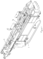
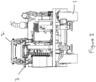
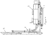
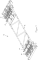
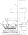
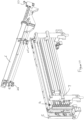
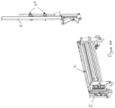
- a drilling rig incorporating a rod handling system in accordance with an embodiment of the present invention comprises a self-propelled tracked chassis 1 having a longitudinal axis aligned with a normal direction of travel and upon which is mounted a drilling mast 2, pivotally mounted at one end of the chassis 1 for movement between a substantially horizontal transport position, as shown in Figures 1 to 3 , and an upright drilling position, as shown in Figure 4 , about a pivot axis extending perpendicular to said longitudinal axis of the chassis.
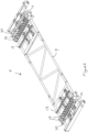
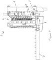
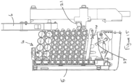
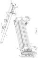
- a rod handling system 3 comprising a rod storage bin 4 incorporating a plurality of vertically stacked drilling rod supports, each rod support being adapted to hold a respective row of drilling rods in side by side relationship in a substantially horizontally extending storage configuration aligned with the longitudinal axis of the chassis; a rod loader 5 having a plurality of rod holders adapted to carry a plurality of drilling rods in side by side relationship, the rod loader 5 being pivotally mounted on a side of the chassis 1 for pivotal movement between an outwardly extending horizontal loading position, as shown in Figures 5 and 9 , with the rod holders facing upwardly, wherein a rod can be placed into or removed from each rod holder, and a vertically arranged transfer position, as shown in Figures 10 to 12 , wherein rods are able to be transferred between each rod holder and an adjacent rod support of the rod storage bin 4; a rod lifter 6 for lifting rods between said substantially horizontal storage configuration and a raised use configuration (for example from 45° to
- the rod loader 5 is located on a first side of the rod storage bin 4, the rod lifter 6 and rod transfer assembly 7 being located on a second side of the rod storage bin 4, opposite said first side.
- the rod loader 5 is pivotally mounted on said one side of the chassis 1 about a horizontal pivot axis parallel to the elongate axis of the chassis 1 for movement between its loading position, wherein the road loader extends substantially horizontally and cantilevered outwardly from said first side of the rod storage bin 4, and its transfer position, wherein said rod loader extends vertically adjacent said first side of the rod storage bin 4 to effectively close and protect said first side of the rod storage bin 4. Hydraulic or pneumatic rams 8 or other actuators may be provided for moving the rod loader 5 between its loading and transfer positions.
- the rod loader 5 comprises a frame 9 upon which is mounted a plurality of spaced pairs of laterally extending divider plates 10 between which a respective rod may be located, such that the pairs of divider plates 10 delimit the rod holders of the rod loader 5.
- the distance between adjacent pairs of divider plates 10 is preferably adjustable so that the rod holders can be adapted to carry rods of different diameters.
- the divider plates 10 are located on an inner side of the frame 9 to extend upwardly when the rod loader 5 is in its loading position and inwardly towards the rod storage bin 4 when the rod loader 5 is in its transfer position.
- the positions of the divider plates 10 on the road loader may also be laterally adjustable on the frame 9 to facilitate alignment of the rod holders with the rod supports and transfer of the rods between the rod holders of the rod loader 5 and the rod supports of the rod storage bin 4.
- the rods are retained between the divider plates 10 defining the rod holders of the rod loader by opposing clamp bars 11, 12 provided at opposite ends of the rod loader 5 and moveable towards and away from one another between a clamping position, wherein the clamp bars 11,12 engage opposite ends of rods located in the rod holders, and a release position, wherein the clamp bars 11,12 are spaced from the ends of the rods.
- Hydraulic or pneumatic rams or other actuators may be provided for moving the clamp bars 11,12 towards their clamping position.
- the clamp bars 11,12 may be spring biased towards their release position.
- the clamp bars 11,12 may be provided with resilient gripping pads to engage and grip the ends of the rods.
- the rod loader 5 preferably includes pushers 13 adapted to move into each rod holder when activated and when the rod loader is in its transfer position, to push a rod located therein out of the respective rod holder and into an adjacent rod support of the rod storage bin 4.
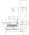
- the rod storage bin 4 comprises vertically stacked rod supports, each rod support being defined by opposing pairs of rod support members in the form of vertically spaced L shaped support plates 14,15 extending transversely to the longitudinal axis of the chassis and having lower portions extending horizontally and inwardly from opposite ends of the rod storage bin 4 and upon which respective ends of the respective rods are supported.
- Each pair of support plates 14,15 of each rod support extend transverse to the elongate axis of the chassis 1 to support a plurality of rods thereon in side by side relationship in a row aligned with the elongate axis of the chassis 1 and along the length of the chassis 1.
- each rod support of the rod storage bin is retained by means of retaining pins extending inwardly from each end of each rod support plate 14,15, each retaining pin being moveable between a retracted position, wherein rods are free to pass laterally into and out of the respective rod support, and an extended position, wherein retaining pins interacts with end regions of the rods in each rod support to prevent said rods from passing laterally out of the respective rod support.
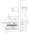
- Each rod support plate 14,15 of each rod support is mounted to be tilted to adjust the angle of the respective rod holder with respect to the horizontal between a first position, shown in Figures 8 and 9 , wherein the rod support plates slope downwardly towards the rod loader, and a second position, shown in Figures 10 to 15 , wherein the rod support plates slope downwardly towards the rod transfer assembly 7.
- each support plate 14,15 of each rod support includes a first retaining pin 16 at one end, adjacent the rod loader 5, said first retaining pins 16 being vertically moveable between a first position, wherein the pins 16 blocks passage of a rod into and out of a respective pair of rod support plate 14,15, and a second position, wherein a rod may pass beneath the first retaining pins 6 to pass into and out of a respective pair of support plates 14,15.
- Each support plate 14,15 of each rod support includes a pair of second retaining pins 17,18 at a second end of the respective support plate 14,15, opposite said first end and adjacent the rod transfer assembly 7, the second pair of retaining pins 17,18 being laterally spaced apart at the approximate spacing of the width of a rod to be held in the rod storage bin 4 to define an outer pin 17 adjacent the second end of the respective support plate 14,15 and an inner pin 18 spaced inwardly from said outer pin 17, each pair of second pins 17,18 being mounted on a common pivot plate 19 arranged such that when the pivot plate 19 is in a first position, the outer pin 17 enters into the path of rods on the respective support plate 14,15 to prevent rods from passing between the respective pair of support plates and the rod transfer assembly 7, with the inner pin 18 of the respective pivot plate 19 out of the path of the rods, and a second position, wherein the inner pin 18 enters into the path of rods on the respective support plate 14,15 and the outer pin 17 moves out of the path of the rods on the respective support plate 14,15 to allow
- the retaining pins 16,17,18 thereby serve as gates at end of each rod support plate 14,15.
- the first retaining pins 16 of each vertical stack of rod supports of the rod storage bin may be moved between their first and second positions by a common actuating mechanism.
- actuating mechanism may interact with the rod loader 5 such that the first retaining pins 16 are moved from their first to their second positions as the rod loader 5 moves to its transfer position.
- the first retaining pins 16 may be biased towards their first position by suitable biasing means, such as a spring.
- each second pair of retaining pins 17,18 of each support plate 14,15 may be urged to its second position by interaction with the rod loader 7 as it moves to its transfer position and may be biased to its first position by means of a respective spring.
- one or both of the retaining pins 17,18 may be operated independently via an actuator, such as a hydraulic actuator or solenoid.
- the rod transfer assembly 7 comprises a spaced apart pair of rod transfer members comprising tiltable V shaped upwardly facing rod cradles 21 for supporting a rod thereon, said cradles 21 being vertically moveable with respect to the rod storage bin to be brought into alignment with each of the rod supports of the rod storage bin 4, as required, and being tiltable between a rod holding position, wherein a rod can be supported thereon, and at least one tilted rod transfer position, whereby a side portion of each cradle 21 is substantially aligned with the adjacent rod support plate 14,15 when in its transfer position such that a rod can be laterally displaced between the rod cradles 21 of the rod transfer assembly 7 and a respective rod support of the rod storage bin 4.
- the rod cradles 21 may be mounted adjacent the rod support plates 14,15 of the rod storage bin 4 and mounted on a lift mechanism, such as a chain and sprocket assembly or a linear actuator/ram, to allow the rod cradles 21 to be moved up and down with respect to the rod support bin 4 to be brought into alignment with respective rod supports.
- a lift mechanism such as a chain and sprocket assembly or a linear actuator/ram
- the rod cradles 21 may be adapted to interact with the pivot plates 19 of the second pair retaining pins 17,18 of respective pairs of rod support plates 14,15 to tilt the adjacent pivot plates 19 to their second positions as the rod cradles 21 are moved to their transfer position adjacent the respective pair of rod support plates 14,15.
- the rod cradles 21 of the rod transfer assembly 7 are adapted to move in the vertical plane of the rod lifter 6 to move selected rods between selected a selected rod support and the rod lifter.
- the rod lifter 6 may be provided with rod clamps 25 to clamp a pipe against a side of the rod lifter 6 and present the rod to the drilling mast 2, as the rod lifter 6 is moved to its vertical position.
- the rod clamps 25 may be adapted to displace a rod clamped therein axially with respect to the rod lifter 6 to bring a rod into the correct position on the drilling mast 2 when the rod lifter 6 is moved to its raised position.
- the rod lifter 6 is rotatable about its longitudinal axis such that the rod clamps 25, mounted on one side of the rod lifter, are moved between a first position on a lower side of the rod lifter 6, to allow rods to be transferred between the rod cradles 21 and the clamps 25 of the rod lifter 6, and a second position on an opposite or upper side of the rod lifter 6 to allow the rods to be presented to the drilling mast 2, as illustrated in Figures 17 to 20 .
- a control system for controlling the operation of the rod handling system in a semi or fully automated matter requiring little or no user interaction, allowing the drilling rig to be operated autonomously or remotely.
- the control system may be programmed to operate the various parts of the rod handling system in a predetermined sequence to control the transfer of rods between the rod loader and the rod storage bin and between the rod storage bin and the rod lifter.
- the rod loader 5 may be operated to fill the rod storage bin 4 with the required drilling rods, the rod loader 5 being lowered to its loading position, the spacing and positions of the divider plates 10 being adjusted to suit the size of rods to be loaded, and rods may be loaded into the rod holders of the rod loader 5 and clamped in place by moving the clamp bars 11,12 to their clamping position.
- the rod loader 5 is then raised to its transfer position, wherein the actuating plates 20 engage the first retaining pins 16 of the rod support plates 14,15 of the rod storage bin 4.
- the actuating plates 20 of the rod loader 5 interact with the first retaining pins 16 to move them to their second position to allow rods to move between the rod loader 5 and the rod supports of the rod storage bin 4 once the clamp bars 11,12 are retracted.
- the positions of the divider plates 10 of the rod loader 5 may be further adjusted to bring the rods to the correct height for transfer into the rod supports of the rod storage bin 4.
- the angle of the support plates 14,15 of the rod storage bin 4 may be adjusted to a rod loading position, for example tilted at an angle of approximately 8° downwardly away from the rod loader 5.
- the pushers 13 are extended to simultaneously push the row of rods from the rod holders of the rod loader 5 into the respective rod supports of the rod storage bin 4. This process is repeated until the rod storage bin 4 is full.
- the drilling rig may then move to a drilling location, preferably via remote control.
- the drilling mast 2 may be moved to its raised position, along with the rod lifter 6, and the rod transfer assembly 7 may be operated to select a rod from the rod storage bin 4, transfer such rod into the rod cradles 21 and then transfer the selected rod into the rod clamp 25 of the rod lifter 21.
- the lifting mechanism of the rod transfer assembly is operated to move the rod cradles 21 into vertical alignment with the selected rod support of the rod storage bin 4 and tilted it its transfer position in alignment with the respective support plates 14,15 of the selected rod support, at the same time acting upon the pivot plates 19 of the adjacent pair of second retaining pins 17,18 to move the outer pins 17 out of the path of the rods, allowing a rod adjacent to the rod cradles 21 to roll into the cradles 21.
- the inner retaining pins 18 are moved into the path of the rods to retain the remaining rods in the selected rod support in place.
- the rod cradles 21 are raised in the vertical plane of the rod lifter 6 until the rod engages the rod clamps 25 of the rod lifter 6 which are then operated to grip the rod.
- the rod lifter 6 may then be raised and rotated to present the rod to the drilling mast.
- the rod clamps 25 may be moved along the rod lifter 6 to axially move the rod into the required position for presenting to the drilling mast 2, for example against a stop 26 on the rod lifter 6, and the rod lifter 6 is raised into alignment with the drilling mast 2 so that the rod may be coupled to the drill string.
- the rod cradles 21 of the transfer assembly 7 may be operated to interact with the rod storage bin to bring the next rod into position to be transferred to the rod lifter 6 when it is returned to its lowered position.
- the rod cradles 21 may be adapted to move to a lowermost position to unload rejected rods to a rejection position, beneath the rod supports of the rod storage bin 4, as illustrated in Figures 14 and 15 . This may take place should a rod selected from the rod storage bin 4 be determined to be an incorrect size or type.
- a moveable stop 27 may be provided to retain a rod in the rejection position prior to release, when the rejected rod may pass out of the rejection position and into a lowermost rod holder of the rod loader 5.
Landscapes
- Engineering & Computer Science (AREA)
- Life Sciences & Earth Sciences (AREA)
- Geology (AREA)
- Mining & Mineral Resources (AREA)
- Mechanical Engineering (AREA)
- Physics & Mathematics (AREA)
- Environmental & Geological Engineering (AREA)
- Fluid Mechanics (AREA)
- General Life Sciences & Earth Sciences (AREA)
- Geochemistry & Mineralogy (AREA)
- Earth Drilling (AREA)
Claims (15)
- Stangenhandhabungssystem (3) für eine Bohranlage, umfassend einen Stangenlagerbehälter (4), der eine Längsachse aufweist; einen Stangenheber (6), der zwischen einer abgesenkten Position und einer angehobenen Position beweglich ist, wobei der Stangenheber (6) angepasst ist, um Stangen zwischen der sich im Wesentlichen horizontal erstreckenden Lagerkonfiguration und einer angehobenen Konfiguration anzuheben, um Stangen einem Bohrkopf zuzuführen; und eine Stangentransferbaugruppe (7), die angepasst ist, um einzelne Stangen zwischen dem Stangenlagerbehälter (4) und dem Stangenheber (6) zu transferieren, dadurch gekennzeichnet, dass der Stangenlagerbehälter (4) eine Vielzahl von vertikal gestapelten Stangenstützen inkorporiert, wobei jede Stangenstütze angepasst ist, um eine jeweilige Reihe von Stangen in einer sich im Wesentlichen horizontal erstreckenden Lagerkonfiguration in einer Seite-an-Seite-Beziehung zu halten, wobei die Stangen mit der Längsachse ausgerichtet sind, wobei das System ferner einen Stangenlader (5) umfasst, der eine Vielzahl von Stangenhaltern aufweist, die angepasst sind, um eine Vielzahl von Stangen in einer Seite-an-Seite-Beziehung zu tragen, die mit der Längsachse ausgerichtet ist, wobei der Stangenlader (5) zwischen einer Ladeposition, in der eine Stange in jeden Stangenhalter platziert oder aus diesem entfernt werden kann, und einer Transferposition bewegbar ist, in der Stangen zwischen jedem Stangenhalter und einer jeweiligen Stangenstütze des Stangenlagerbehälters (4) transferiert werden können.
- System nach Anspruch 1, wobei der Stangenlader (5) auf einer ersten Seite des Stangenlagerbehälters (4) lokalisiert ist, während der Stangenheber (6) und die Stangentransferbaugruppe (7) auf einer zweiten Seite des Stangenlagerbehälters (4) lokalisiert sind, die der ersten Seite gegenüberliegt.
- System nach Anspruch 2, wobei der Stangenlader (5) für eine Schwenkbewegung um eine horizontale Schwenkachse parallel zu der Längsachse für eine Bewegung zwischen der Ladeposition, in der sich der Stangenlader (5) von der ersten Seite des Stangenlagerbehälters (4) nach außen erstreckt, wobei die Stangenhalter nach oben zeigen, um zu ermöglichen, dass Stangen darin platziert werden, und der Transferposition, in der sich der Stangenlader (5) vertikal benachbart zu der ersten Seite des Stangenlagerbehälters (4) erstreckt, montiert ist.
- System nach Anspruch 3, wobei der Stangenlader (5) die erste Seite des Stangenlagerbehälters (4) verschließt, wenn er in seiner Transferposition ist.
- System nach einem der vorhergehenden Ansprüche, wobei jeder Stangenhalter des Stangenladers (5) durch ein oder mehrere beabstandete Paare von sich seitlich erstreckenden Trennplatten (10) definiert ist, zwischen denen eine jeweilige Stange lokalisiert sein kann, und wobei der Abstand zwischen benachbarten Paaren von Trennplatten (10) einstellbar sein kann, so dass die Stangenhalter Stangen mit unterschiedlichen Durchmessern tragen können.
- System nach einem der vorhergehenden Ansprüche, wobei Stangen in den Stangenhaltern des Stangenladers (5) durch gegenüberliegende Klemmstäbe (11, 12) festgehalten werden, die an gegenüberliegenden Enden des Stangenladers (5) bereitgestellt sind und zwischen einer Klemmposition, in der die Klemmstäbe (11, 12) in die gegenüberliegenden Enden der in den Stangenhaltern lokalisierten Stangen eingreifen, und einer Freigabeposition, in der die Klemmstäbe (11, 12) von den Enden der Stangen beabstandet sind, aufeinander zu und voneinander weg beweglich sind.
- System nach einem der vorhergehenden Ansprüche, wobei der Stangenlader (5) Schieber (13) beinhaltet, die angepasst sind, um sich in jeden Stangenhalter hineinzubewegen, wenn sie aktiviert sind und wenn der Stangenlader in seiner Transferposition ist, um eine darin lokalisierte Stange aus den Stangenhaltern heraus und in benachbarte Stangenstützen des Stangenlagerbehälters (4) zu schieben.
- System nach einem der vorhergehenden Ansprüche, wobei jede Stangenstütze des Stangenlagerbehälters (4) ein Paar von Stützelementen (14, 15) umfasst, die sich von gegenüberliegenden Enden des Stangenlagerbehälters nach innen erstrecken und auf denen jeweilige Enden der jeweiligen Stangen gestützt sind.
- System nach einem der vorhergehenden Ansprüche, wenn abhängig von Anspruch 2, wobei der Stangenheber (6) für eine Bewegung zwischen der abgesenkten und der angehobenen Position um eine Schwenkachse schwenkbar montiert ist, die sich senkrecht zu der Längsachse erstreckt und derart an einem Ende des Stangenlagerbehälters (4) lokalisiert ist, dass sich der Stangenheber (6) in einem Bogen durch eine vertikale Ebene bewegt.
- System nach Anspruch 9, wobei die Stangentransferbaugruppe (7) mindestens einen Stangenträger (24) zum Tragen einer ausgewählten Stange umfasst, wobei der mindestens eine Stangenträger (24) in Bezug auf den Stangenlagerbehälter vertikal beweglich ist.
- System nach Anspruch 10, wobei der Stangenträger ein Paar von Stangengerüsten (24) umfasst, die in Bezug auf den Stangenlagerbehälter (4) vertikal beweglich sind, um einen Transfer von Stangen zwischen einer ausgewählten Stangenstütze und der Stangentransferbaugruppe (7) zu erleichtern, wobei die Stangengerüste (24) kippbare, V-förmige, nach oben zeigende Stützelemente umfassen, die zwischen einer aufrechten Stangenhalteposition und mindestens einer gekippten Stangentransferposition beweglich sind, wobei die Stangengerüste angepasst sind, um Stangen zwischen dem Stangenheber (6) und ausgewählten Stangenstützen des Stangenlagerbehälters (4) zu transferieren, wenn der Stangenheber (6) in seiner abgesenkten Position ist.
- System nach einem der vorhergehenden Ansprüche, wobei Stangenklemmen (25) mit dem Stangenheber (6) assoziiert sind, um eine Stange derart gegen die Stangenstützen zu klemmen, dass die Stange auf dem Stangenheber (6) festgehalten werden kann, wenn er sich in seine angehobene Position bewegt.
- Stangenhandhabungssystem nach einem der vorhergehenden Ansprüche, das auf einem selbstfahrenden mobilen Fahrgestell montiert ist, das auf Raupen gestützt ist, und ein Antriebsmittel zum Antreiben der Raupen beinhaltet.
- Stangenhandhabungssystem nach einem der vorhergehenden Ansprüche, das eine Steuerung beinhaltet, die programmiert ist, um den Betrieb des Systems mindestens halbautonom zu steuern.
- Bohranlage, die ein Fahrgestell und einen Bohrmast aufweist, der zwischen einer angehobenen und einer abgesenkten Position beweglich ist, und ein Stangenhandhabungssystem (3) nach einem der vorhergehenden Ansprüche aufweist.
Applications Claiming Priority (2)
| Application Number | Priority Date | Filing Date | Title |
|---|---|---|---|
| GB2208007.1A GB2619308B (en) | 2022-05-31 | 2022-05-31 | Rod handling system for a drilling rig |
| PCT/EP2023/063561 WO2023232511A1 (en) | 2022-05-31 | 2023-05-22 | Rod handling system for a drilling rig |
Publications (3)
| Publication Number | Publication Date |
|---|---|
| EP4532887A1 EP4532887A1 (de) | 2025-04-09 |
| EP4532887B1 true EP4532887B1 (de) | 2025-07-02 |
| EP4532887C0 EP4532887C0 (de) | 2025-07-02 |
Family
ID=82324256
Family Applications (1)
| Application Number | Title | Priority Date | Filing Date |
|---|---|---|---|
| EP23729024.2A Active EP4532887B1 (de) | 2022-05-31 | 2023-05-22 | Stangenhandhabungssystem für eine bohranlage |
Country Status (7)
| Country | Link |
|---|---|
| US (1) | US20250347183A1 (de) |
| EP (1) | EP4532887B1 (de) |
| AU (1) | AU2023281812A1 (de) |
| CA (1) | CA3257825A1 (de) |
| GB (1) | GB2619308B (de) |
| WO (1) | WO2023232511A1 (de) |
| ZA (1) | ZA202409181B (de) |
Families Citing this family (1)
| Publication number | Priority date | Publication date | Assignee | Title |
|---|---|---|---|---|
| CN119308597B (zh) * | 2024-09-20 | 2025-11-18 | 中煤科工西安研究院(集团)有限公司 | 一种定向钻机自动装卸长钻具系统及控制方法 |
Family Cites Families (10)
| Publication number | Priority date | Publication date | Assignee | Title |
|---|---|---|---|---|
| US3612286A (en) * | 1969-10-22 | 1971-10-12 | Byron Jackson Inc | Horizontal pipe rack |
| US3844420A (en) * | 1969-10-22 | 1974-10-29 | Byron Jackson Inc | Pipe racking apparatus |
| NO303059B1 (no) * | 1996-09-13 | 1998-05-25 | Hitec Asa | Anordning for Õ pakke r÷r inn i og ut av en kasse |
| CA2396333A1 (en) * | 2000-01-13 | 2001-07-19 | Maritime Hydraulics As | Horizontal pipe handling device |
| CA2470815A1 (en) * | 2004-05-28 | 2005-11-28 | Wilbert A. Skaley | Support for a pipe clamps |
| US7600584B2 (en) * | 2004-09-21 | 2009-10-13 | The Charles Machine Works, Inc. | Pipe handling system with a movable magazine |
| CA2551884C (en) * | 2005-07-19 | 2009-12-15 | National-Oilwell, L.P. | Single joint drilling system with inclined pipe handling system |
| AU2005337415B2 (en) * | 2005-10-07 | 2011-08-18 | Marl Technologies Inc. | Apparatus and method for handling pipe sections |
| US10808466B2 (en) * | 2018-01-26 | 2020-10-20 | The Charles Machine Works, Inc. | Pipe handling assembly |
| US11408236B2 (en) * | 2020-07-06 | 2022-08-09 | Canrig Robotic Technologies As | Robotic pipe handler systems |
-
2022
- 2022-05-31 GB GB2208007.1A patent/GB2619308B/en active Active
-
2023
- 2023-05-22 WO PCT/EP2023/063561 patent/WO2023232511A1/en not_active Ceased
- 2023-05-22 EP EP23729024.2A patent/EP4532887B1/de active Active
- 2023-05-22 AU AU2023281812A patent/AU2023281812A1/en active Pending
- 2023-05-22 CA CA3257825A patent/CA3257825A1/en active Pending
- 2023-05-22 US US18/870,942 patent/US20250347183A1/en active Pending
-
2024
- 2024-11-29 ZA ZA2024/09181A patent/ZA202409181B/en unknown
Also Published As
| Publication number | Publication date |
|---|---|
| GB202208007D0 (en) | 2022-07-13 |
| AU2023281812A1 (en) | 2024-12-19 |
| EP4532887A1 (de) | 2025-04-09 |
| GB2619308A (en) | 2023-12-06 |
| EP4532887C0 (de) | 2025-07-02 |
| CA3257825A1 (en) | 2023-12-07 |
| US20250347183A1 (en) | 2025-11-13 |
| ZA202409181B (en) | 2025-07-30 |
| GB2619308B (en) | 2024-05-15 |
| WO2023232511A1 (en) | 2023-12-07 |
Similar Documents
| Publication | Publication Date | Title |
|---|---|---|
| CN111433430B (zh) | 用于钻杆装卸的排序 | |
| CN109281626B (zh) | 一种岩心取样钻机 | |
| US8186925B2 (en) | Drill rod handler | |
| AU712046B2 (en) | Articulated bit-selector coring tool | |
| AU2008202526B2 (en) | Improved Drill Rig | |
| US7537424B2 (en) | Apparatus and method for handling pipe sections | |
| US10837243B2 (en) | Pipe handling column racker with retractable arm | |
| CN101449024B (zh) | 钻杆处理机 | |
| US9097102B2 (en) | Downhole coring tools and methods of coring | |
| EP4532887B1 (de) | Stangenhandhabungssystem für eine bohranlage | |
| CN119221843B (zh) | 一种钻杆连续连接式地质勘探设备 | |
| CN114086951B (zh) | 一种矿产地质勘查设备 | |
| US20130341088A1 (en) | Apparatus associated with sub-sea operations | |
| EP4409107B1 (de) | Vorrichtung und verfahren zum stützen eines kragenbereichs eines sprenglochs während des bohrens | |
| AU2019280082A1 (en) | Drilling and boring system for diamond drilling | |
| US4351398A (en) | Well drilling apparatus | |
| WO2025233385A1 (en) | Drill rig | |
| NL2016209B1 (en) | Removal of tubing from a well and discarding the removed tubing | |
| Reedman | Deep Sampling Methods |
Legal Events
| Date | Code | Title | Description |
|---|---|---|---|
| STAA | Information on the status of an ep patent application or granted ep patent |
Free format text: STATUS: UNKNOWN |
|
| STAA | Information on the status of an ep patent application or granted ep patent |
Free format text: STATUS: THE INTERNATIONAL PUBLICATION HAS BEEN MADE |
|
| PUAI | Public reference made under article 153(3) epc to a published international application that has entered the european phase |
Free format text: ORIGINAL CODE: 0009012 |
|
| STAA | Information on the status of an ep patent application or granted ep patent |
Free format text: STATUS: REQUEST FOR EXAMINATION WAS MADE |
|
| 17P | Request for examination filed |
Effective date: 20241127 |
|
| AK | Designated contracting states |
Kind code of ref document: A1 Designated state(s): AL AT BE BG CH CY CZ DE DK EE ES FI FR GB GR HR HU IE IS IT LI LT LU LV MC ME MK MT NL NO PL PT RO RS SE SI SK SM TR |
|
| GRAP | Despatch of communication of intention to grant a patent |
Free format text: ORIGINAL CODE: EPIDOSNIGR1 |
|
| STAA | Information on the status of an ep patent application or granted ep patent |
Free format text: STATUS: GRANT OF PATENT IS INTENDED |
|
| DAV | Request for validation of the european patent (deleted) | ||
| DAX | Request for extension of the european patent (deleted) | ||
| INTG | Intention to grant announced |
Effective date: 20250423 |
|
| GRAS | Grant fee paid |
Free format text: ORIGINAL CODE: EPIDOSNIGR3 |
|
| GRAA | (expected) grant |
Free format text: ORIGINAL CODE: 0009210 |
|
| STAA | Information on the status of an ep patent application or granted ep patent |
Free format text: STATUS: THE PATENT HAS BEEN GRANTED |
|
| AK | Designated contracting states |
Kind code of ref document: B1 Designated state(s): AL AT BE BG CH CY CZ DE DK EE ES FI FR GB GR HR HU IE IS IT LI LT LU LV MC ME MK MT NL NO PL PT RO RS SE SI SK SM TR |
|
| REG | Reference to a national code |
Ref country code: GB Ref legal event code: FG4D |
|
| REG | Reference to a national code |
Ref country code: CH Ref legal event code: EP |
|
| REG | Reference to a national code |
Ref country code: DE Ref legal event code: R096 Ref document number: 602023004555 Country of ref document: DE |
|
| REG | Reference to a national code |
Ref country code: IE Ref legal event code: FG4D |
|
| U01 | Request for unitary effect filed |
Effective date: 20250724 |
|
| U07 | Unitary effect registered |
Designated state(s): AT BE BG DE DK EE FI FR IT LT LU LV MT NL PT RO SE SI Effective date: 20250731 |
|
| PG25 | Lapsed in a contracting state [announced via postgrant information from national office to epo] |
Ref country code: IS Free format text: LAPSE BECAUSE OF FAILURE TO SUBMIT A TRANSLATION OF THE DESCRIPTION OR TO PAY THE FEE WITHIN THE PRESCRIBED TIME-LIMIT Effective date: 20251102 |
|
| PG25 | Lapsed in a contracting state [announced via postgrant information from national office to epo] |
Ref country code: NO Free format text: LAPSE BECAUSE OF FAILURE TO SUBMIT A TRANSLATION OF THE DESCRIPTION OR TO PAY THE FEE WITHIN THE PRESCRIBED TIME-LIMIT Effective date: 20251002 |
|
| PG25 | Lapsed in a contracting state [announced via postgrant information from national office to epo] |
Ref country code: HR Free format text: LAPSE BECAUSE OF FAILURE TO SUBMIT A TRANSLATION OF THE DESCRIPTION OR TO PAY THE FEE WITHIN THE PRESCRIBED TIME-LIMIT Effective date: 20250702 |
|
| PG25 | Lapsed in a contracting state [announced via postgrant information from national office to epo] |
Ref country code: GR Free format text: LAPSE BECAUSE OF FAILURE TO SUBMIT A TRANSLATION OF THE DESCRIPTION OR TO PAY THE FEE WITHIN THE PRESCRIBED TIME-LIMIT Effective date: 20251003 |
|
| PG25 | Lapsed in a contracting state [announced via postgrant information from national office to epo] |
Ref country code: CZ Free format text: LAPSE BECAUSE OF FAILURE TO SUBMIT A TRANSLATION OF THE DESCRIPTION OR TO PAY THE FEE WITHIN THE PRESCRIBED TIME-LIMIT Effective date: 20250702 |
|
| PG25 | Lapsed in a contracting state [announced via postgrant information from national office to epo] |
Ref country code: PL Free format text: LAPSE BECAUSE OF FAILURE TO SUBMIT A TRANSLATION OF THE DESCRIPTION OR TO PAY THE FEE WITHIN THE PRESCRIBED TIME-LIMIT Effective date: 20250702 |
|
| PG25 | Lapsed in a contracting state [announced via postgrant information from national office to epo] |
Ref country code: RS Free format text: LAPSE BECAUSE OF FAILURE TO SUBMIT A TRANSLATION OF THE DESCRIPTION OR TO PAY THE FEE WITHIN THE PRESCRIBED TIME-LIMIT Effective date: 20251002 |
|
| PG25 | Lapsed in a contracting state [announced via postgrant information from national office to epo] |
Ref country code: ES Free format text: LAPSE BECAUSE OF FAILURE TO SUBMIT A TRANSLATION OF THE DESCRIPTION OR TO PAY THE FEE WITHIN THE PRESCRIBED TIME-LIMIT Effective date: 20250702 |
|
| PG25 | Lapsed in a contracting state [announced via postgrant information from national office to epo] |
Ref country code: SM Free format text: LAPSE BECAUSE OF FAILURE TO SUBMIT A TRANSLATION OF THE DESCRIPTION OR TO PAY THE FEE WITHIN THE PRESCRIBED TIME-LIMIT Effective date: 20250702 |