EP4531356A2 - Sendeverfahren und empfangsverfahren für optische kommunikation und entsprechende vorrichtung - Google Patents
Sendeverfahren und empfangsverfahren für optische kommunikation und entsprechende vorrichtung Download PDFInfo
- Publication number
- EP4531356A2 EP4531356A2 EP24213634.9A EP24213634A EP4531356A2 EP 4531356 A2 EP4531356 A2 EP 4531356A2 EP 24213634 A EP24213634 A EP 24213634A EP 4531356 A2 EP4531356 A2 EP 4531356A2
- Authority
- EP
- European Patent Office
- Prior art keywords
- symbols
- polarization
- frame
- pilot
- sub
- Prior art date
- Legal status (The legal status is an assumption and is not a legal conclusion. Google has not performed a legal analysis and makes no representation as to the accuracy of the status listed.)
- Pending
Links
Images


Classifications
-
- H—ELECTRICITY
- H04—ELECTRIC COMMUNICATION TECHNIQUE
- H04L—TRANSMISSION OF DIGITAL INFORMATION, e.g. TELEGRAPHIC COMMUNICATION
- H04L27/00—Modulated-carrier systems
- H04L27/26—Systems using multi-frequency codes
- H04L27/2601—Multicarrier modulation systems
- H04L27/2602—Signal structure
- H04L27/261—Details of reference signals
- H04L27/2613—Structure of the reference signals
-
- H—ELECTRICITY
- H04—ELECTRIC COMMUNICATION TECHNIQUE
- H04B—TRANSMISSION
- H04B10/00—Transmission systems employing electromagnetic waves other than radio-waves, e.g. infrared, visible or ultraviolet light, or employing corpuscular radiation, e.g. quantum communication
- H04B10/50—Transmitters
- H04B10/516—Details of coding or modulation
- H04B10/532—Polarisation modulation
-
- H—ELECTRICITY
- H04—ELECTRIC COMMUNICATION TECHNIQUE
- H04B—TRANSMISSION
- H04B10/00—Transmission systems employing electromagnetic waves other than radio-waves, e.g. infrared, visible or ultraviolet light, or employing corpuscular radiation, e.g. quantum communication
- H04B10/50—Transmitters
- H04B10/516—Details of coding or modulation
- H04B10/54—Intensity modulation
- H04B10/541—Digital intensity or amplitude modulation
-
- H—ELECTRICITY
- H04—ELECTRIC COMMUNICATION TECHNIQUE
- H04B—TRANSMISSION
- H04B10/00—Transmission systems employing electromagnetic waves other than radio-waves, e.g. infrared, visible or ultraviolet light, or employing corpuscular radiation, e.g. quantum communication
- H04B10/60—Receivers
- H04B10/61—Coherent receivers
- H04B10/612—Coherent receivers for optical signals modulated with a format different from binary or higher-order PSK [X-PSK], e.g. QAM, DPSK, FSK, MSK, ASK
-
- H—ELECTRICITY
- H04—ELECTRIC COMMUNICATION TECHNIQUE
- H04L—TRANSMISSION OF DIGITAL INFORMATION, e.g. TELEGRAPHIC COMMUNICATION
- H04L1/00—Arrangements for detecting or preventing errors in the information received
- H04L1/0001—Systems modifying transmission characteristics according to link quality, e.g. power backoff
- H04L1/0006—Systems modifying transmission characteristics according to link quality, e.g. power backoff by adapting the transmission format
- H04L1/0007—Systems modifying transmission characteristics according to link quality, e.g. power backoff by adapting the transmission format by modifying the frame length
- H04L1/0008—Systems modifying transmission characteristics according to link quality, e.g. power backoff by adapting the transmission format by modifying the frame length by supplementing frame payload, e.g. with padding bits
-
- H—ELECTRICITY
- H04—ELECTRIC COMMUNICATION TECHNIQUE
- H04L—TRANSMISSION OF DIGITAL INFORMATION, e.g. TELEGRAPHIC COMMUNICATION
- H04L27/00—Modulated-carrier systems
- H04L27/26—Systems using multi-frequency codes
- H04L27/2601—Multicarrier modulation systems
- H04L27/2602—Signal structure
-
- Y—GENERAL TAGGING OF NEW TECHNOLOGICAL DEVELOPMENTS; GENERAL TAGGING OF CROSS-SECTIONAL TECHNOLOGIES SPANNING OVER SEVERAL SECTIONS OF THE IPC; TECHNICAL SUBJECTS COVERED BY FORMER USPC CROSS-REFERENCE ART COLLECTIONS [XRACs] AND DIGESTS
- Y02—TECHNOLOGIES OR APPLICATIONS FOR MITIGATION OR ADAPTATION AGAINST CLIMATE CHANGE
- Y02D—CLIMATE CHANGE MITIGATION TECHNOLOGIES IN INFORMATION AND COMMUNICATION TECHNOLOGIES [ICT], I.E. INFORMATION AND COMMUNICATION TECHNOLOGIES AIMING AT THE REDUCTION OF THEIR OWN ENERGY USE
- Y02D30/00—Reducing energy consumption in communication networks
- Y02D30/70—Reducing energy consumption in communication networks in wireless communication networks
Definitions
- This application relates to the field of optical communication, and in particular, to a transmission method and a reception method for optical communication, and a corresponding device.
- a coherent optical communication system uses the amplitude, phase, polarization, and frequency of light waves to carry information.
- a coherent optical communication system usually adds some designed fixed symbol sequences to a transmission symbol sequence, so as to help a receiver end restore transmitted symbols.
- An existing transmission symbol sequence is mainly applied to a 400-Gbps scenario, and cannot adapt to a future scenario of over 400 Gbps (including 600 Gbps, 800 Gbps, and the like).
- 400 Gbps including 600 Gbps, 800 Gbps, and the like.
- This application provides a transmission method for optical communication, to resolve the problems of an inability of the conventional technology to be applied to a scenario of over 400 Gbps, and a poor cross-correlation between symbol sequences in different polarization directions.
- a reception method for optical communication includes: receiving a super-frame including a plurality of sub-frames, where the sub-frame includes training symbols and pilot symbols; in one polarization direction, a sum of quantities of training symbols and pilot symbols included in the sub-frame is not less than 5, and there is one symbol that is both a training symbol and a pilot symbol; and each of the training symbols and the pilot symbols is one of -A-Aj, -A+Aj, A-Aj, or A+Aj, A being a real number; in the training symbols and the pilot symbols included in each sub-frame, quantities of -A-Aj, -A+Aj, A-Aj, and A+Aj in one polarization direction are respectively N TS + N PS ⁇ 1 / 4 , N TS + N PS ⁇ 1 / 2 ⁇ N TS + N PS ⁇ 1 / 4 , (N TS +N PS -1)/2- N TS + N PS ⁇ 1
- one sub-frame in each polarization direction, includes a total of N TS +N PS -1 training symbols and pilot symbols. For these symbols, a difference between quantities of -A-Aj, -A+Aj, A-Aj, and A+Aj is not greater than 1.
- quantities of the four complex numbers representing the training symbols and the pilot symbols are the same in the two polarization directions, and are all (N TS +N PS -1)/2, thereby effectively ensuring a balance between symbol quantities.
- a sequence consisting of the training symbols and a sequence consisting of the pilot symbols achieve direct current (DC) balance, which facilitates quality of a signal restored at a receiver end.
- DC direct current
- a sequence consisting of training symbols in one polarization direction is different from a sequence consisting of training symbols in the other polarization direction
- a sequence consisting of pilot symbols in one polarization direction is different from a sequence consisting of pilot symbols in the other polarization direction.
- the training symbols are consecutively arranged in the sub-frame, and in either of the polarization directions, in the training symbols included in the sub-frame, a quantity of consecutive same real part elements is not greater than 5, and a quantity of consecutive same imaginary part elements is not greater than 5. Further, in either of the polarization directions, a quantity of consecutive same training symbols in one sub-frame does not exceed 4.
- a training sequence obtained in this condition facilitates clock recovery, thereby helping improve quality of a signal restored at the receiver end.
- the plurality of sub-frames further include a first sub-frame, the first sub-frame includes consecutively arranged frame alignment word symbols, and each frame alignment word symbol is one of -A-Aj, -A+Aj, A-Aj, and A+Aj; and in either of the polarization directions, in the frame alignment word symbols included in the sub-frame, a quantity of consecutive same real part elements is not greater than 5, and a quantity of consecutive same imaginary part elements is not greater than 5. Further, in either of the polarization directions, a quantity of consecutive same frame alignment word symbols in the first sub-frame does not exceed 4.
- a frame alignment word sequence obtained in this condition also facilitates clock recovery, thereby helping improve quality of a signal restored at the receiver end.
- quantities of -A-Aj, -A+Aj, A-Aj, and A+Aj in one polarization direction are respectively N FAW / 4 , N FAW / 2 ⁇ N FAW / 4 , N FAW / 2 ⁇ N FAW / 4 , and N FAW / 4 , and quantities thereof in the other polarization direction are respectively N FAW / 2 ⁇ N FAW / 4 , N FAW / 4 , N FAW / 4 , and N FAW / 2 ⁇ N FAW / 4 , where N FAW is a quantity of the frame alignment word symbols in the first sub-frame in one polarization direction, and N FAW is an even number.
- This embodiment ensures that the plurality of frame alignment word symbols meet direct current balance, and a difference between quantities of the four available symbols -A-Aj, -A+Aj, A-Aj, and A+Aj is not greater than 1, which facilitates quality of a signal restored at the receiver end.
- N TS is an even number
- quantities of -A-Aj, -A+Aj, A-Aj, and A+Aj in one polarization direction are respectively N TS / 4 , N TS / 2 ⁇ N TS / 4 , N TS / 2 ⁇ N TS / 4 , and N TS / 4
- quantities thereof in the other polarization direction are respectively N TS / 2 ⁇ N TS / 4 , N TS / 4 , N TS / 4 , and N TS / 2 ⁇ N TS / 4 .
- N TS is an odd number
- quantities of -A-Aj, -A+Aj, A-Aj, and A+Aj in one polarization direction are respectively N TS ⁇ 1 / 4 , N TS ⁇ 1 / 2 ⁇ N TS ⁇ 1 / 4 , N TS ⁇ 1 / 2 ⁇ N TS ⁇ 1 / 4 , and N TS ⁇ 1 / 4
- quantities thereof in the other polarization direction are respectively (N TS - 1 / 2 ⁇ N TS ⁇ 1 / 4 , N TS ⁇ 1 / 4 , N TS ⁇ 1 / 4 , and N TS ⁇ 1 / 2 ⁇ N TS ⁇ 1 / 4 .
- the foregoing two embodiments provide the quantities of several possible symbols of the training sequence in different polarization directions in two different cases, and the quantities of training symbols -A-Aj, - A+Aj, A-Aj, and A+Aj included in one sub-frame are close to each other.
- the training symbol that is also used as a pilot symbol if there are an odd number of training symbols
- a sum of real parts of complex numbers corresponding to the other training symbols is 0, and a sum of imaginary parts thereof is also 0, so that direct current balance can be achieved, which facilitates quality of a signal restored at the receiver end.
- N PS is an even number
- quantities of -A-Aj, -A+Aj, A-Aj, and A+Aj in one polarization direction are respectively N PS / 4 , N PS / 2 ⁇ N PS / 4 , N PS / 2 ⁇ N PS / 4 , and N PS / 4
- quantities thereof in the other polarization direction are respectively N PS / 2 ⁇ N PS / 4 , N PS / 4 , N PS / 4 , and N PS / 2 ⁇ N PS / 4 .
- N PS is an odd number
- a ninth possible implementation in each sub-frame, a remainder of a quantity of pilot symbols in one polarization direction divided by 4 is 0, and in the pilot symbols included in each sub-frame, quantities of -A-Aj, -A+Aj, A-Aj, and A+Aj in one polarization direction are respectively N PS /4+1, N PS /4-1, N PS /4-1, and N PS /4+1, and quantities thereof in the other polarization direction are respectively N PS /4-1, N PS /4+1, N PS /4+1, and N PS /4-1; or quantities thereof in both polarization directions are N PS /4.
- a remainder of a quantity of pilot symbols in one polarization direction divided by 4 is 2, and in the pilot symbols included in each sub-frame, quantities of -A-Aj, -A+Aj, A-Aj, and A+Aj in one polarization direction are respectively (N PS -2)/4, (N PS -2)/4+1, (N PS -2)/4+1, and (N PS -2)/4, and quantities thereof in the other polarization direction are respectively (N PS -2)/4+1, (N PS -2)/4, (N PS -2)/4, and (N PS -2)/4+1.
- a remainder of a quantity of pilot symbols in one polarization direction divided by 4 is 1, and in the pilot symbols included in each sub-frame, except the pilot symbol that is also used as a training symbol, quantities of -A-Aj, -A+Aj, A-Aj, and A+Aj in one polarization direction are respectively (N PS -1)/4+1, (N PS -1)/4-1, (N PS -1)/4-1, and (N PS -1)/4+1, and quantities thereof in the other polarization direction are respectively (N PS -1)/4-1, (N PS -1)/4+1, (N PS -1)/4+1, and (N PS -1)/4-1; or quantities thereof in both polarization directions are (N PS -1)/4.
- a remainder of a quantity of pilot symbols in one polarization direction divided by 4 is 3, and in the pilot symbols included in each sub-frame, except the pilot symbol that is also used as a training symbol, quantities of -A-Aj, -A+Aj, A-Aj, and A+Aj in one polarization direction are respectively (N PS -3)/4, (N PS -3)/4+1, (N PS -3)/4+1, and (N PS -3)/4, and quantities thereof in the other polarization direction are respectively (N PS -3)/4+1, (N PS -3)/4, (N PS -3)/4, and (N PS -3)/4+1.
- the seventh to the twelfth implementations provide the quantities of several possible symbols of the pilot sequence in different polarization directions in several different cases, and the quantities of pilot symbols -A-Aj, -A+Aj, A-Aj, and A+Aj included in one sub-frame are close to each other, thereby effectively ensuring balance between the training symbols.
- the pilot symbol that is also used as a training symbol if there are an odd number of pilot symbols
- a sum of real parts of the complex numbers corresponding to the other pilot symbols is 0, and a sum of imaginary parts thereof is also 0, so that direct current balance can be achieved, which facilitates quality of a signal restored at the receiver end.
- a modulation format of the symbols in the super-frame is 16QAM, and a value of A is 1 or 3.
- symbols in a constellation diagram may be compressed, and the value of A is also compressed accordingly.
- power normalization is performed on the 16 symbols in the 16QAM constellation diagram, in which case the value is changed to ⁇ 1 10 ⁇ 1 10 j , ⁇ 1 10 ⁇ 3 10 j , ⁇ 3 10 ⁇ 1 10 j , ⁇ 3 10 ⁇ 3 10 j , and the value of A is 1 10 or 3 10 .
- the training symbols and the pilot symbols when the pilot symbols and the training symbols, -A-Aj, -A+Aj, A-Aj, and A+Aj, are the outermost four symbols in the constellation diagram, the training symbols and the pilot symbols have a relatively high sensitivity (sensitivity), but have a relatively large peak-to-average power (peak to average power) ratio; and when the values of the pilot symbols and the training symbols, -A-Aj, -A+Aj, A-Aj, and A+Aj, are the innermost four symbols in the constellation diagram, the training symbols and the pilot symbols have relatively small noise (noise), but have a relatively low sensitivity (sensitivity).
- the pilot symbols and the training symbols may not be symbols in the constellation diagram of the used modulation format, and may be four symbols in a middle area between the outermost four symbols and the innermost four symbols in the constellation diagram.
- the training symbols and the pilot symbols have fair noise and sensitivity, but have a relatively low peak-to-average power ratio.
- values of the 16 symbols in the 16QAM constellation diagram are ⁇ 1 ⁇ 1j, ⁇ 1 ⁇ 3j, ⁇ 3 ⁇ 1j, ⁇ 3 ⁇ 3j 1, and a value of the real number A meets 1 ⁇ A ⁇ 3.
- the outermost four symbols in the constellation diagram are 3 + 3j, 3 - 3j, -3 + 3j, and -3 - 3j
- the innermost four symbols in the constellation diagram are 1 + 1j, 1 - 1j, -1 + 1j, and -1 - 1j.
- the values of the pilot symbols and the training symbols, -A-Aj, -A+Aj, A-Aj, and A+Aj may be four symbols in the middle area between the outermost four symbols and the innermost four symbols in the 16QAM constellation diagram.
- a specific value of the real number A may be selected according to an actual application scenario, so that the peak-to-average power ratio, noise, and sensitivity of the training symbols and the pilot symbols have a good compromise.
- the real number A 5
- the values of the pilot symbols and the training symbols are ⁇ 5 ⁇ 5 j , ⁇ 5 + 5 j , 5 ⁇ 5 j , 5 + 5 j .
- the 16 symbols in the 16QAM constellation diagram are subjected to power normalization and have values of ⁇ 1 10 ⁇ 1 10 j , ⁇ 1 10 ⁇ 3 10 j , ⁇ 3 10 ⁇ 1 10 j , ⁇ 3 10 ⁇ 3 10 j
- the value of the real number A meets 1 10 ⁇ A ⁇ 3 10 .
- the real number A 2 2
- the values of the pilot symbols and the training symbols are ⁇ 2 2 ⁇ 2 2 j , ⁇ 2 2 + 2 2 j , 2 2 ⁇ 2 2 j , 2 2 + 2 2 j .
- a symbol at a fixed position in every 48 symbols is the pilot symbol.
- the 1 st symbol in every 48 symbols is the pilot symbol.
- a transmitting device for optical communication includes a processor and a memory.
- the memory is configured to store instructions
- the processor is configured to execute the instructions, to cause the transmitting device to perform the method in any one of the first aspect or the possible implementations of the first aspect.
- a computer-readable storage medium stores instructions that, when executed on a terminal device, cause the terminal device to perform the method in any one of the first aspect or the possible implementations of the first aspect, or cause the terminal device to perform the method in any one of the second aspect or the possible implementations of the second aspect.
- a computer program product including instructions is provided.
- the computer program product when run on a terminal device, causes the terminal device to perform the method according to any one of the first aspect or the possible implementations of the first aspect, or causes the terminal device to perform the method according to any one of the second aspect or the possible implementations of the second aspect.
- the terminal device may be a chip, a processor, or the like, which is not limited in this application.
- a reception method for optical communication includes: receiving a super-frame including a plurality of sub-frames, where the sub-frame includes training symbols and pilot symbols; in one polarization direction, there is one symbol that is both a training symbol and a pilot symbol, and each of the training symbols and the pilot symbols is one of -A-Aj, -A+Aj, A-Aj, and A+Aj, A being a real number; in each sub-frame, in the one polarization direction, the pilot symbols are generated based on a target polynomial and a seed, there are N PS pilot symbols combined with N TS training symbols to achieve direct current balance, N TS is a quantity of the training symbols in each sub-frame in one polarization direction, and N TS +N PS is an odd number; and the target polynomial is one item in the following table; and Index Target polynomial 1 x 10 +x 9 + x 8 + x 7 + x 6 +1 2 x 10 +
- the pilot symbol is generated based on the target polynomial and the corresponding seed.
- the target polynomial is any item in the foregoing Table, and the target polynomial and the corresponding seed can meet that a combination of the generated N PS pilot symbols and N TS training symbols achieves direct current balance, that is, in one polarization direction, a sum of real parts of complex numbers corresponding to the training symbols and the pilot symbols in one sub-frame is 0, and a sum of imaginary parts thereof is also 0, which helps a receiver end restore a signal better, and improves quality of the signal at the receiver end.
- Such a super-frame structure can help the receiver end restore a signal better, and improve quality of the signal at the receiver end.
- a normalized amplitude of a sidelobe value of a periodic autocorrelation function of pilot symbols in the same polarization direction is not greater than 0.2
- a normalized amplitude of a periodic cross-correlation function value of pilot symbols in different polarization directions is not greater than 0.2:
- the ninth aspect when the target polynomial and hexadecimal seeds in two polarization directions are one row in the following Table, in one polarization direction, in a combination of 114 pilot symbols and 11 training symbols, quantities of -A-Aj, -A+Aj, A-Aj, and A+Aj in one polarization direction are all 31: Index Target polynomial Seed in the direction of polarization 1 Seed in the direction of polarization 2 1 x 10 + x 9 + x 8 + x 7 + x 6 +1 0x046 0x384 2 x 10 + x 9 + x 8 + x 7 + x 6 +1 0x046 0x3 C4 3 x 10 + x 9 + x 6 + x 3 +1 0x076 0x07C 4 x 10 + x 8 + x 7 + x 4 + x 3 +1 0x1A
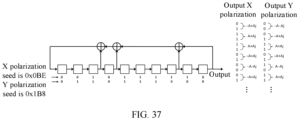
- the ninth aspect when the target polynomial is a primitive polynomial and there are no more than 5 non-zero terms of the target polynomial, and when the target polynomial and hexadecimal seeds in two polarization directions are one row in the following Table, a normalized amplitude of a sidelobe value of a periodic autocorrelation function of pilot symbols in the same polarization direction is not greater than 0.25, and a normalized amplitude of a periodic cross-correlation function value of pilot symbols in different polarization directions is not greater than 0.25: Index Target polynomial Seed in the direction of polarization 1 Seed in the direction of polarization 2 1 x 10 + x 9 + x 7 + x 3 +1 0x23E 0x094 2 x 10 + x 7 + x 6 + x 2 +1 0x0BE 0x1B8 3 x 10 + x 9 + x 6 +x
- the ninth aspect in another possible implementation, when the target polynomial is x 10 + x 7 + x 3 + x + 1, and the corresponding hexadecimal seeds in the two polarization directions are 0x34E and 0x084, in one polarization direction, in a combination of 114 pilot symbols and 11 training symbols, quantities of -A-Aj, -A+Aj, A-Aj, and A+Aj in the one polarization direction are all 31, and the respective 114 pilot symbols in the two polarization directions are shown in the following table: Polarization direction Pilot symbol Polarization 1 -A+Aj, A+Aj, -A-Aj, A-Aj, A+Aj, -A+Aj, A-Aj, A+Aj, -A-Aj, -A-Aj, A+Aj, -A-Aj, A+Aj, -A-Aj, A+Aj, -A-Aj, -A+Aj, -A
- the target polynomial is x 10 + x 7 + x 6 + x 2 + 1, and the corresponding hexadecimal seeds in the two polarization directions are 0x0BE and 0x1B8, the respective 114 pilot symbols in the two polarization directions are shown in the following table: Polarization direction Pilot symbol Polarization 1 -A+Aj, A+Aj, A+Aj, -A+Aj, -A-Aj, -A+Aj, -A+Aj, -A+Aj, -A+Aj, A-Aj, A+Aj, A-Aj, -A-Aj, -A+Aj, -A+Aj, A-Aj, -A+Aj, A-Aj, -A-Aj, A+Aj, -A+Aj, A-Aj, -A-Aj, A+Aj, -A+Aj, A-Aj, -A-Aj, A+Aj
- a normalized amplitude of a sidelobe value of a periodic autocorrelation function of pilot symbols in the same polarization direction is not greater than 0.23
- a normalized amplitude of a periodic cross-correlation function value of pilot symbols in different polarization directions is not greater than 0.23:
- the ninth aspect when the target polynomial is x 10 + x 7 + x 3 + x+ 1, and the corresponding hexadecimal seeds in the two polarization directions are 0x0B 1 and 0x3E9, the respective 57 pilot symbols in the two polarization directions are shown in the following table: Polarization direction Pilot symbol Polarization 1 A-Aj, -A-Aj, A+Aj, -A+Aj, -A-Aj, -A+Aj, A+Aj, -A-Aj, -A+Aj, A+Aj, A+Aj, A-Aj, -A-Aj, -A+Aj, A+Aj, A+Aj, -A+Aj, -A+Aj, A+Aj, A+Aj, -A+Aj, -A+Aj, A+Aj, -A+Aj, -A+Aj, A+Aj, -A+Aj,
- a transmitting device for optical communication includes a processor and a memory.
- the memory is configured to store instructions
- the processor is configured to execute the instructions, to cause the transmitting device to perform the method in any one of the eighth aspect or the possible implementations of the eighth aspect.
- a receiving device for optical communication includes a processor and a memory.
- the memory is configured to store instructions
- the processor is configured to execute the instructions, to cause the receiving device to perform the method in any one of the ninth aspect or the possible implementations of the ninth aspect.
- a system for optical communication includes the transmitting device according to the tenth aspect and the receiving device according to the tenth aspect.
- the processor may be a central processing unit (Central Processing Unit, "CPU” for short), or may be another general-purpose processor, a digital signal processor (DSP), an application-specific integrated circuit (ASIC), a field-programmable gate array (FPGA) or another programmable logic device, a discrete gate or a transistor logic device, a discrete hardware component, or the like.
- the general-purpose processor may be a microprocessor, or the processor may be any conventional processor or the like, which is not limited in embodiments of this application.
- a computer-readable storage medium stores instructions that, when executed on a terminal device, cause the terminal device to perform the method in any one of the eighth aspect or the possible implementations of the eighth aspect, or cause the terminal device to perform the method in any one of the ninth aspect or the possible implementations of the ninth aspect.
- a computer program product including instructions is provided.
- the computer program product when run on a terminal device, causes the terminal device to perform the method according to any one of the eighth aspect or the possible implementations of the eighth aspect, or causes the terminal device to perform the method according to any one of the ninth aspect or the possible implementations of the ninth aspect.
- the terminal device may be a chip, a processor, or the like, which is not limited in this application.
- a transmission method for optical communication includes: generating a super-frame including a plurality of sub-frames, where the sub-frame includes training symbols and pilot symbols; in each sub-frame, in one polarization direction, there are N PS pilot symbols, a value of which is one of -A 2 -A 2 j, -A 2 +A 2 j, A 2 -A 2 j, and A 2 +A 2 j, A 2 being a real number, and N PS being an even number; the N PS pilot symbols achieve direct current balance, and a combination of the training symbols and the N PS pilot symbols achieves direct current balance; the pilot symbols are generated based on a target polynomial and a seed, the target polynomial is a primitive polynomial, and there are no more than 5 non-zero terms of the target polynomial; and the target polynomial is one item in the following Table; and Index Target polynomial 1 x 10 +x 9 +x 7 +x 6
- a reception method for optical communication includes: receiving a super-frame including a plurality of sub-frames, where the sub-frame includes training symbols and pilot symbols; in each sub-frame, in one polarization direction, there are N PS pilot symbols, a value of which is one of -A 2 -A 2 j, -A 2 +A 2 j, A 2 -A 2 j, and A 2 +A 2 j, A 2 being a real number, and N PS being an even number; the N PS pilot symbols achieve direct current balance, and a combination of the training symbols and the N PS pilot symbols achieves direct current balance; the pilot symbols are generated based on a target polynomial and a seed, the target polynomial is a primitive polynomial, and there are no more than 5 non-zero terms of the target polynomial; and the target polynomial is one item in the following Table; and Index Target polynomial 1 x 10 +x 9 +x 7 +x 6
- the pilot symbols are generated based on the target polynomial and the seed.
- the target polynomial is any item in the foregoing Table, and the target polynomial and the corresponding seed can meet that the N PS pilot symbols achieve direct current balance, and that a combination of the training symbols and the N PS pilot symbols achieves direct current balance, which helps a receiver end restore a signal better, and improves quality of the signal at the receiver end.
- the sixteenth aspect in each sub-frame, in one polarization direction, when a remainder of the quantity of the pilot symbols divided by 4 is 0, in the pilot symbols included in each sub-frame, a quantity of -A 2 -A 2 j is equal to a quantity of A 2 +A 2 j, a quantity of -A 2 +A 2 j is equal to a quantity of A 2 -A 2 j, and a difference between the quantity of -A 2 -A 2 j and a quantity of is 2; or the quantities of -A 2 -A 2 j, -A 2 +A 2 j, A 2 -A 2 j, and A 2 +A 2 j are equal; and when a remainder of the quantity of the pilot symbols divided by 4 is 2, in the pilot symbols included in each sub-frame, a quantity of -A 2 -A 2 j is equal to a quantity of A 2 +A 2 j, a
- a transmitting device for optical communication includes a processor and a memory.
- the memory is configured to store instructions
- the processor is configured to execute the instructions, to cause the transmitting device to perform the method in any one of the fifteenth aspect or the possible implementations of the fifteenth aspect.
- a receiving device for optical communication includes a processor and a memory.
- the memory is configured to store instructions
- the processor is configured to execute the instructions, to cause the receiving device to perform the method in any one of the sixteenth aspect or the possible implementations of the sixteenth aspect.
- the processor may be a central processing unit (Central Processing Unit, "CPU” for short), or may be another general-purpose processor, a digital signal processor (DSP), an application-specific integrated circuit (ASIC), a field-programmable gate array (FPGA) or another programmable logic device, a discrete gate or a transistor logic device, a discrete hardware component, or the like.
- the general-purpose processor may be a microprocessor, or the processor may be any conventional processor or the like, which is not limited in embodiments of this application.
- a computer-readable storage medium stores instructions that, when executed on a terminal device, cause the terminal device to perform the method in any one of the fifteenth aspect or the possible implementations of the fifteenth aspect, or cause the terminal device to perform the method in any one of the sixteenth aspect or the possible implementations of the sixteenth aspect.
- a computer program product including instructions is provided.
- the computer program product when run on a terminal device, causes the terminal device to perform the method in any one of the fifteenth aspect or the possible implementations of the fifteenth aspect, or causes the terminal device to perform the method in any one of the sixteenth aspect or the possible implementations of the sixteenth aspect.
- the terminal device may be a chip, a processor, or the like, which is not limited in this application.
- a difference between quantities of -A-Aj, -A+Aj, A-Aj, and A+Aj that represent the training symbols and the pilot symbols is not greater than 1, thereby effectively ensuring equalization between symbols.
- a sum of real parts of the complex numbers corresponding to the training symbols and the pilot symbols in one sub-frame is 0, and a sum of imaginary parts thereof is also 0, so that direct current balance can be achieved, which facilitates quality of a signal restored at the receiver end.
- FIG. 1 is a block diagram of a structure of a communication system.
- a source provides a data stream to be transmitted.
- An encoder receives and encodes the data stream.
- Codeword information that is obtained through encoding and that combines parity bits and information bits is sent to a transmitting-end signal processor for framing, and is transmitted through a channel to a receiver end.
- the receiver end After receiving a distorted signal caused by noise or other impairments in the channel, the receiver end sends the signal to a receiver-end signal processor for dispersion compensation, alignment, phase recovery, and other operations.
- a decoder decodes the signal to restore the original data and sends the data to a destination.
- the encoding method provided in this application is applied to the transmitting-end signal processor shown in FIG. 1 , and is a very important part in the communication system.
- a framing process may be shown in FIG. 2 or FIG. 3 .
- symbol mapping is performed on a received data sequence, including, but not limited to, quadrature phase shift keying (Quadrature Phase Shift Keying, QPSK) and quadrature amplitude modulation (Quadrature Amplitude Modulation, QAM), and then polarization symbol distribution is performed to obtain dual-polarization (Dual-polarization, DP) symbols, for example, DP-QPSK, DP-8QAM, DP-16QAM, DP-32QAM, and DP-64QAM.
- QPSK Quadrature Phase Shift Keying
- QAM Quadrature Amplitude Modulation
- the following framing is performed on a specific quantity of dual-polarization symbols: inserting frame alignment word symbols, training symbols, reserved symbols, and pilot symbols in each of X and Y polarization directions to obtain a dual-polarization symbol sequence to be transmitted, which is referred to as a super-frame (super-frame).
- a super-frame super-frame
- symbols may be further interleaved, and the foregoing framing is performed on the interleaved symbols.
- one dual-polarization symbol may be represented by two symbols, one of which is in an X polarization direction, and the other in a Y polarization direction. Each symbol may be represented by a complex number.
- a symbol modulated using 16QAM may be represented by any one of the following 16 complex numbers: ⁇ 1 ⁇ 1j, ⁇ 1 ⁇ 3j, ⁇ 3 ⁇ 1j, and ⁇ 3 ⁇ 3j. It should be understood that, in some cases, the real part and the imaginary part may be normalized, but the essence does not change.
- a sequence having N dual-polarization symbols may be completely represented by two complex sequences having a length of N, where one complex sequence represents symbols on the X polarization, and the other complex sequence represents symbols on the Y polarization.
- Each complex sequence with a length of N is represented by a real part sequence with a length of N and an imaginary part sequence with a length of N, where N is an integer greater than 1.
- interleaving may be further performed on the bit sequence into which the bits corresponding to the symbols are inserted, and then the symbol mapping and polarization symbol distribution are performed to obtain the same super-frame as that obtained in the operation in FIG. 2 .
- interleaving may be further performed on the bit sequence into which the bits corresponding to the symbols are inserted, and then the symbol mapping and polarization symbol distribution are performed to obtain the same super-frame as that obtained in the operation in FIG. 2 .
- An embodiment of this application provides a transmission method for optical communication. As shown in FIG. 4 , the transmission method includes the following steps.
- a value of A is determined by a modulation format used when a symbol is generated.
- both training symbols and pilot symbols are the outermost four symbols in the constellation diagram, as indicated by the hollow symbols in FIG. 5A .
- each training symbol may be represented by one of -3-3j, -3+3j, 3-3j, and 3+3j.
- training symbols represented by the four complex numbers also all exist, and the same is true for pilot symbols.
- A ⁇ 1, ⁇ 3, ⁇ 5, or ⁇ 7.
- A ⁇ 5 or ⁇ 7.
- each training symbol may be represented by one of -5-5j, -5+5j, 5-5j, and 5+5j.
- training symbols represented by the four complex numbers all exist.
- pilot symbols the same is true for pilot symbols.
- a higher-order modulation format may be used, and details are not described in this application. In an actual transmission process, this can result in a relatively low probability of symbol errors, facilitating channel estimation.
- symbols in a constellation diagram may be compressed, and the value of A is also compressed accordingly.
- power normalization is performed on the 16 symbols in the 16QAM constellation diagram, in which case the value is changed to ⁇ 1 10 ⁇ 1 10 j , ⁇ 1 10 ⁇ 3 10 j , ⁇ 3 10 ⁇ 1 10 j , ⁇ 3 10 ⁇ 3 10 j , and the value of A is 1 10 or 3 10 .
- another manner of normalization may be used, which is not limited in this application.
- the training symbols and the pilot symbols when the pilot symbols and the training symbols, -A-Aj, -A+Aj, A-Aj, and A+Aj, are the outermost four symbols in the constellation diagram, the training symbols and the pilot symbols have a relatively high sensitivity (sensitivity), but have a relatively large peak-to-average power (peak to average power) ratio; and when the values of the pilot symbols and the training symbols, -A-Aj, -A+Aj, A-Aj, and A+Aj, are the innermost four symbols in the constellation diagram, the training symbols and the pilot symbols have relatively small noise (noise), but have a relatively low sensitivity (sensitivity).
- the pilot symbols and the training symbols may not be symbols in the constellation diagram of the used modulation format, and may be four symbols in a middle area between the outermost four symbols and the innermost four symbols in the constellation diagram.
- the training symbols and the pilot symbols have fair noise and sensitivity, but have a relatively low peak-to-average power ratio.
- values of the 16 symbols in the 16QAM constellation diagram are ⁇ ⁇ 1 ⁇ 1j, ⁇ 1 ⁇ 3j, ⁇ 3 ⁇ 1j, ⁇ 3 ⁇ 3j ⁇ , and a value of the real number A meets 1 ⁇ A ⁇ 3. More specifically, as shown in FIG. 5B , the outermost four symbols in the constellation diagram are 3 + 3j, 3 - 3j, -3 + 3j, and -3 - 3j, and the innermost four symbols in the constellation diagram are 1 + 1j, 1 - 1j, -1 + 1j, and -1 - 1j.
- the values of the pilot symbols and the training symbols, -A-Aj, -A+Aj, A-Aj, and A+Aj may be four symbols in the middle area between the outermost four symbols and the innermost four symbols in the 16QAM constellation diagram.
- a specific value of the real number A may be selected according to an actual application scenario, so that the peak-to-average power ratio, noise, and sensitivity of the training symbols and the pilot symbols have a good compromise.
- the real number A 5
- the values of the pilot symbols and the training symbols are ⁇ 5 ⁇ 5 j , ⁇ 5 + 5 j , 5 ⁇ 5 j , 5 + 5 j .
- the 16 symbols in the 16QAM constellation diagram are subjected to power normalization and have values of ⁇ 1 10 ⁇ 1 10 j , ⁇ 1 10 ⁇ 3 10 j , ⁇ 3 10 ⁇ 1 10 j , ⁇ 3 10 ⁇ 3 10 j
- the value of the real number A meets 1 10 ⁇ A ⁇ 3 10 .
- the real number A 2 2
- the values of the pilot symbols and the training symbols are ⁇ 2 2 ⁇ 2 2 j , ⁇ 2 2 + 2 2 j , 2 2 ⁇ 2 2 j , 2 2 + 2 2 j .
- the two polarization directions are orthogonal to each other.
- the other polarization direction is the Y polarization; and when one polarization direction is the Y polarization, the other polarization direction is the X polarization.
- N TS +N PS -1 which is not less than 5. Because one symbol is both a training symbol and a pilot symbol, the sum of quantities is not N TS +N PS , and is one less than the sum of quantities of the two types of symbols.
- a sequence consisting of training symbols in one polarization direction is different from a sequence consisting of training symbols in the other polarization direction
- a sequence consisting of pilot symbols in one polarization direction is different from a sequence consisting of pilot symbols in the other polarization direction
- a sequence consisting of training symbols in one polarization direction is -A-Aj, -A-Aj, A+Aj, and A-Aj
- a sequence consisting of training symbols in the other polarization direction cannot be the same according to the same sequence, and may be -A-Aj, -A-Aj, A+Aj, and A+Aj, that is, one of the symbols is different, so as to avoid the problem that a receiver end cannot distinguish the two polarization directions in actual transmission.
- one sub-frame in each polarization direction, includes N TS +N PS -1 training symbols and pilot symbols in total, that is, a total quantity of -A-Aj, -A+Aj, A-Aj, and A+Aj that represent the training symbols and the pilot symbols is N TS +N PS -1, and a difference between quantities of the four symbols is not greater than 1.
- quantities of the four complex numbers (-A-Aj, -A+Aj, A-Aj, and A+Aj) that represent the training symbols and the pilot symbols are the same in the two polarization directions, and are both (N TS +N PS -1)/2, which effectively ensures that symbol quantity balance.
- a sum of real parts of the complex numbers corresponding to the training symbols and the pilot symbols in one sub-frame is 0, and a sum of imaginary parts thereof is also 0, so that direct current balance can be achieved, which facilitates quality of a signal restored at the receiver end.
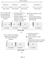
- a super-frame (superframe) in this application which may also be referred to as a multi-frame (multiframe), includes a plurality of sub-frames, and has a structure shown in (a) in FIG. 6 .
- Each sub-frame includes a same quantity of symbols (N S symbols).
- N S symbols There are mainly two types of sub-frames.
- One type of sub-frame includes frame alignment word symbols, and is usually the 1 st sub-frame in the super-frame, but the possibility is not ruled out that the sub-frame is in another position in the super-frame.
- the other sub-frames are of a second type.
- a structure of a first-type sub-frame is shown in (b) in FIG. 6 .
- the first N TS symbols in the sub-frame are training symbols, which may be used for link training and/or sub-frame alignment.
- the 1 st symbol of the sub-frame is both a training symbol and a pilot symbol.
- any one of the first N TS symbols may be both a training symbol and a pilot symbol, which is not limited in this application.
- a symbol at a fixed position in every 64 symbols or 48 symbols is a pilot symbol, which is used for carrier phase recovery.
- the 1 st symbol in every 64 symbols is a pilot symbol, providing a diagram of a frame structure of the first-type sub-frame.
- the pilot signal is followed by a plurality of frame alignment word symbols, which are used for alignment between super-frames.
- the frame alignment word symbols may be used together with the training symbols for alignment between super-frames, or may be used together with the pilot symbols to implement the same function. It should be understood that the frame alignment word symbols are consecutively arranged, and may be adjacent to the training signals, which case is shown in (b) in FIG. 6 . Alternatively, there may be a gap of one or more symbols between the frame alignment word signals and the training signals.
- there are usually a plurality of reserved symbols which may be reserved for other purposes in the future.
- the reserved symbols may be in one of the plurality of second-type sub-frames, which is not limited in this application.
- the remaining symbols are symbols before framing that include information and parity bits, where the pilot symbol does not overlap the reserved symbol or the symbol before framing. For example, there is no symbol that is both a pilot symbol and a symbol before framing.
- a frame structure of the second-type sub-frame is shown in (c) in FIG. 6 .
- the first N TS symbols in the sub-frame are also training symbols.
- the 1 st symbol of the sub-frame is both a training symbol and a pilot symbol.
- any one of the first N TS symbols may be both a training symbol and a pilot symbol, which is not limited in this application.
- a symbol at a fixed position in every 64 symbols or 48 symbols is also a pilot symbol, which is used for carrier phase recovery.
- the 1 st symbol in every 64 symbols is a pilot symbol, providing a diagram of a frame structure of the second-type sub-frame.
- the other symbols are generally symbols before framing including information and parity bits, where the pilot symbol does not overlap with the symbol before framing.
- the other parameters are all symbol quantities, which may be understood as a quantity of dual-polarization symbols, or may be understood as a quantity of symbols in one polarization direction.
- quantities of different symbols in two polarization directions are the same. For example, there are 10 training symbols in one polarization direction, and there are also 10 training symbols in the other polarization direction. On the whole, there are 10 dual-polarization training symbols. Subsequent tables may all be understood in this way, which is not repeated in this application.
- a quantity New of symbols before framing is 172032.
- an open FEC Open FEC, OFEC
- the 1 st symbol in every 64 symbols is a pilot symbol.
- a quantity N CW of symbols before framing is 175616.
- a CFEC encoding scheme is used.
- the 1 st symbol in every 48 symbols is a pilot symbol.
- a quantity N CW of symbols before framing is 172032.
- an OFEC encoding scheme is used.
- the 1 st symbol in every 48 symbols is a pilot symbol.
- training symbols are consecutively arranged in a sub-frame.
- a quantity of consecutive real-part elements "-A” or “A” is not greater than M0
- a quantity of consecutive imaginary part elements "-A” or “A” is not greater than M0.
- a quantity of consecutive same training symbols in one sub-frame does not exceed M1, where both M0 and M1 are positive integers, and 2 ⁇ M1 ⁇ M0 ⁇ 5.
- a training sequence obtained in this condition facilitates clock recovery, thereby helping improve quality of a signal restored at the receiver end.
- a quantity of consecutive real part elements "-A” or “A” is not greater than 5, and a quantity of consecutive imaginary part elements "-A” or “A” is not greater than 5.
- the real part elements have five consecutive -A, which meets the requirement of this embodiment.
- the real part elements have six consecutive -A, which does not meet the requirement of this embodiment. Further, in one polarization direction, a quantity of consecutive same training symbols in one sub-frame does not exceed 4. In this case, the sequence -A-Aj, -A-Aj, -A-Aj, -A-Aj, -A-Aj, and A+Aj that originally meet the requirement no longer meets the requirement of this embodiment because there are five consecutive -A-Aj.
- N TS is an even number, that is, in each sub-frame, there are an even number of training symbols in one polarization direction
- quantities of -A-Aj, -A+Aj, A-Aj, and A+Aj in one polarization direction are respectively N TS / 4 , N TS / 2 ⁇ N TS / 4 , N TS / 2 ⁇ N TS / 4 , and N TS / 4
- quantities thereof in the other polarization direction are respectively N TS / 2 ⁇ N TS / 4 , N TS / 4 , N TS / 4 , and N TS /2-[N TS /4].
- N PS is definitely an odd number, that is, in each sub-frame, there are an odd number of pilot symbols in one polarization direction.
- -A-Aj, -A+Aj, A-Aj, and A+Aj may also meet the following condition: Quantities thereof in one polarization direction are respectively N PS ⁇ 1 / 4 , N PS ⁇ 1 / 2 ⁇ N PS ⁇ 1 / 4 , N PS ⁇ 1 / 2 ⁇ N PS ⁇ 1 / 4 , and N PS ⁇ 1 / 4 , and quantities thereof in the other polarization direction are respectively N PS ⁇ 1 / 2 ⁇ N PS ⁇ 1 / 4 , N PS ⁇ 1 / 4 , N PS ⁇ 1 / 4 , and N PS ⁇ 1 / 2 ⁇ N PS ⁇ 1 / 1 / 1 /
- N TS is an odd number, that is, in each sub-frame, there are an odd number of training symbols in one polarization direction, in the training symbols included in each sub-frame, except the training symbol that is also used as a pilot symbol
- quantities of -A-Aj, -A+Aj, A-Aj, and A+Aj in one polarization direction are respectively N TS ⁇ 1 / 4 , N TS ⁇ 1 / 2 ⁇ N TS ⁇ 1 / 4 , N TS ⁇ 1 / 2 ⁇ N TS ⁇ 1 / 4 , and N TS ⁇ 1 / 4
- quantities thereof in the other polarization direction are respectively N TS ⁇ 1 / 2 ⁇ N TS ⁇ 1 / 4 , N TS ⁇ 1 / 4 , N TS ⁇ 1 / 4 , and N TS ⁇ 1 / 2 ⁇ N TS ⁇ 1 / 4 .
- N PS is definitely an even number, that is, in each sub-frame, there are an even number of pilot symbols in one polarization direction.
- -A-Aj, -A+Aj, A-Aj, and A+Aj may also meet the following condition: Quantities thereof in one polarization direction are respectively N PS / 4 , N PS / 2 ⁇ N PS / 4 , N PS / 2 ⁇ N PS / 4 , and N PS / 4 , and quantities thereof in the other polarization direction are respectively N PS / 2 ⁇ N PS / 4 , N PS / 4 , N PS / 4 , and N PS / 2 ⁇ N PS / 4 .
- N TS is an odd number, in one sub-frame, except the training symbol that is also used as a pilot symbol, quantities of four different symbols (in the form of complex numbers) representing the training symbols in the two polarization directions are the same, quantities of the four symbols are all (N TS -1)/2, a sum of real parts of the complex numbers corresponding to the N TS -1 training symbols is 0, and a sum of imaginary parts thereof is also 0.
- N TS is an odd number
- quantities of four different symbols in the form of complex numbers representing the training symbols in the two polarization directions
- quantities of the four symbols are all (N TS -1)/2
- a sum of real parts of the complex numbers corresponding to the N TS -1 training symbols is 0, and a sum of imaginary parts thereof is also 0.
- quantities of -A-Aj, -A+Aj, A-Aj, and A+Aj in one polarization direction are respectively N PS /4+1, N PS /4-1, N PS /4-1, and N PS /4+1, and quantities thereof in the other polarization direction are respectively N PS /4-1, N PS /4+1, N PS /4+1, and N PS /4-1; or quantities thereof in both polarization directions are N PS /4.
- quantities of -A-Aj, -A+Aj, A-Aj, and A+Aj in one polarization direction are respectively (N PS -1)/4+1, (N PS -1)/4-1, (N PS -1)/4-1, and (N PS -1)/4+1, and quantities thereof in the other polarization direction are respectively (N PS -1)/4-1, (N PS -1)/4+1, (N PS -1)/4+1, and (N PS -1)/4-1; or quantities thereof in both polarization directions are (N PS -1)/4.
- a difference between quantities of the pilot symbols -A-Aj, -A+Aj, A-Aj, and A+Aj included in one sub-frame is relatively small, thereby effectively ensuring balance between symbols.
- the pilot symbol that is also used as a training symbol if there are an odd number of pilot symbols
- a sum of real parts of the complex numbers corresponding to the other pilot symbols is 0, and a sum of imaginary parts thereof is also 0, so that direct current balance can be achieved, which facilitates quality of a signal restored at the receiver end.
- the first-type sub-frame further includes frame alignment word symbols, as shown in (b) in FIG. 6 .
- a plurality of frame alignment word symbols are consecutively arranged in the first-type sub-frame, and each frame alignment word symbol is one of -A-Aj, -A+Aj, A-Aj, and A+Aj, where a value of A corresponding to the frame alignment word symbol is also determined by a modulation format used, which is consistent with the method of determining a value of A corresponding to a training symbol and a pilot symbol described in the foregoing embodiment, and details are not described herein again.
- each of the frame alignment word symbols is one of -A-Aj, -A+Aj, A-Aj, and A+Aj
- a value of A corresponding to the frame alignment word symbols may be a real number different from that corresponding to the training symbols and the pilot symbols described in the foregoing embodiment.
- the values of A are equal in this application.
- a quantity of consecutive real part elements "-A” or “A” is not greater than M2
- a quantity of consecutive imaginary part elements "-A” or “A” is not greater than M2.
- a quantity of consecutive same frame alignment word symbols in the first-type sub-frame does not exceed M3, where both M2 and M3 are positive integers, and 2 ⁇ M3 ⁇ M2 ⁇ 5.
- a frame alignment word sequence obtained in this condition facilitates clock recovery, thereby helping improve quality of a signal restored at the receiver end.
- a quantity of consecutive real part elements "-A” or “A” is not greater than 5
- a quantity of consecutive imaginary part elements "-A” or “A” is not greater than 5.
- a quantity of consecutive same frame alignment word symbols in the first-type sub-frame does not exceed 4.
- N FAW is a quantity of the frame alignment word symbols in the first-type sub-frame in one polarization direction.
- This condition ensures that the plurality of frame alignment word symbols meet direct current balance, and a difference between quantities of the four available symbols -A-Aj, -A+Aj, A-Aj, and A+Aj is not greater than 1, which facilitates quality of a signal restored at the receiver end.
- N FAW 22
- quantities of symbols -A-Aj, -A+Aj, A-Aj, and A+Aj in the X polarization direction are respectively 5, 6, 6, and 5, and quantities of symbols -A-Aj, -A+Aj, A-Aj, and A+Aj in the Y polarization direction are respectively 6, 5, 5, and 6, where the two polarization directions are perpendicular to each other.
- N FAW 24
- quantities of symbols -A-Aj, -A+Aj, A-Aj, and A+Aj in either polarization direction is 6, and inter-symbol balance and direct current balance can be achieved, which facilitates quality of a signal restored at the receiver end.
- this application provides some possible symbol sequences, including a frame alignment word sequence consisting of frame alignment word symbols in a first-type sub-frame, a training sequence consisting of training symbols in each sub-frame, and a pilot sequence consisting of pilot symbols in each sub-frame. Training sequences in different sub-frames are the same, and pilot sequences in different sub-frames are also the same.
- the frame alignment word sequence may be any item in Table 5. It should be understood that one index corresponds to a group of frame alignment word sequences in two polarizations, and one item represents the sequences corresponding to one index.
- a polarization 1 for any item in the table is the X polarization
- a polarization 2 is the Y polarization
- the polarization 1 is the Y polarization
- the polarization 2 is the X polarization.
- the frame alignment word sequence may be any item in Table 6.
- Table 6 Index Polarization Frame alignment word sequence 1 Polarization 1 A-Aj, A-Aj, A+Aj, -A+Aj, -A+Aj, A-Aj, A+Aj, A-Aj, -A+Aj, A+Aj, A+Aj, -A-Aj, A+Aj, -A-Aj, A+Aj, -A-Aj, -A+Aj, A+Aj, -A-Aj, -A-Aj, -A-Aj Polarization 2 A+Aj, A+Aj, -A+Aj, A-Aj, -A-Aj, -A-Aj, -A+Aj, A-Aj, A-Aj, -A+Aj, A-Aj, A-Aj, -A+Aj, A-Aj, A-Aj, -A+Aj, A-Aj,
- the frame alignment word sequence may be any item in Table 7.
- Table 7 Index Polarization Frame alignment word sequence 1 Polarization 1 -A+Aj, -A+Aj, A-Aj, -A-Aj, -A+Aj, A-Aj, A+Aj, A-Aj, -A-Aj, A-Aj, A+Aj, -A+Aj, A+Aj, -A-Aj, A+Aj, A-Aj, A-A-Aj, A+Aj, -A+Aj, -A-Aj, A+Aj, -A+Aj, -A-Aj Polarization 2 -A+Aj, -A+Aj, A-Aj, A+Aj, -A+Aj, A-Aj, -A-Aj, A-Aj, A+Aj, A-Aj, -A-Aj, -A+Aj, -Aj Polarization 2 -A+Aj,
- pilot sequences there may be the following several possible pilot sequences, which can ensure a relatively good cross-correlation between pilot sequences in the two polarization directions.
- N PS 48. If a remainder of N TS divided by 4 is 1, the pilot sequence is one item in the following Table 8-1. If a remainder of N TS divided by 4 is 3, the pilot sequence is one item in the following Table 8-1 or Table 8-2.
- N TS +N PS is an odd number; if N PS is an even number, N TS needs to be an odd number, and the remainder of N TS divided by 4 is definitely 1 or 3; and if N ps is an odd number, N TS needs to be an even number, and the remainder of N TS divided by 4 is definitely 0 or 2, which is not repeated later.
- the pilot sequence is one item in the following Table 10-1. If a remainder of N TS divided by 4 is 0, the pilot sequence is one item in the following Table 10-1. If a remainder of N TS divided by 4 is 2, the pilot sequence is one item in the following Table 10-1 or Table 10-2.
- any item is selected from the following Table 12-2 as a pilot sequence in one polarization, and any item is selected from the following Table 12-3 as a pilot sequence in the other polarization.
- any item is selected from the following Table 12-4 as a pilot sequence in one polarization, and any item is selected from the following Table 12-5 as a pilot sequence in the other polarization.
- the pilot sequence is one item in the following Table 13-1. If a remainder of N TS divided by 4 is 3, the pilot sequence is one item in the following Table 13-1 or Table 13-2.
- any item is selected from Table 15-2 as a pilot sequence in one polarization, and any item is selected from Table 15-3 as a pilot sequence in the other polarization.
- any item is selected from Table 15-4 as a pilot sequence in one polarization, and any item is selected from the following Table 15-5 as a pilot sequence in the other polarization.
- the pilot sequence is one item in Table 16-1 or Table 16-2.
- Table 16-1 Index Polarization Pilot sequence 1 Polarization 1 -A-Aj, -A-Aj, A+Aj, A+Aj, A-Aj, A-Aj, -A+Aj, A+Aj, A-Aj, A+Aj, A+Aj, -A-Aj, -A+Aj, -A+Aj, A+Aj, - A-Aj, A+Aj, A-Aj, A+Aj, -A-Aj, -A+Aj, A-Aj, A-Aj, A+Aj, -A-Aj, A-Aj, A+Aj, -A-Aj, A-Aj, A+Aj, -A-Aj, -Aj, A+Aj, -A-Aj, -Aj, A-Aj, A+Aj, -A-Aj, -Aj, A-
- any item is selected from Table 18-2 as a pilot sequence in one polarization, and any item is selected from Table 18-3 as a pilot sequence in the other polarization.
- any item is selected from Table 18-4 as a pilot sequence in one polarization, and any item is selected from Table 18-5 as a pilot sequence in the other polarization.
- any item is selected from Table 20-2 as a pilot sequence in one polarization, and any item is selected from Table 20-3 as a pilot sequence in the other polarization.
- any item is selected from Table 20-4 as a pilot sequence in one polarization, and any item is selected from Table 20-5 as a pilot sequence in the other polarization.
- the pilot sequence is one item in the following Table 21-1 or Table 21-2.
- Table 21-1 Index Polarization Pilot sequence 1 Polarization 1 A-Aj, A+Aj, -A+Aj, -A+Aj, -A+Aj, -A-Aj, -A-Aj, A+Aj, -A+Aj, -A-Aj, -A-Aj, A+Aj, -A+Aj, -A-Aj, -A-Aj, A+Aj, A-Aj, A-Aj, -A+Aj, -A-Aj, -A+Aj, A-Aj, A+Aj, A-Aj, A+Aj, A-Aj, A+Aj, A-Aj, A+Aj, A-Aj, A+Aj, A-Aj, A+Aj, A-Aj, A+Aj, A-Aj, A+Aj, A-Aj, A+Aj,
- the pilot sequence is one item in the following Table 23-1 or Table 23-2.
- Table 23-1 Index Polarization Pilot sequence 1 Polarization 1 -A-Aj, A+Aj, -A+Aj, A+Aj, A-Aj, A-Aj, -A-Aj, A-Aj, -A+Aj, A+Aj, -A+Aj, A+Aj, -A+Aj, -A-Aj, A+Aj, A+Aj, A-Aj, -A-Aj, -A+Aj, -A-Aj, A-Aj, A+Aj, -A+Aj, -A+Aj, A+Aj, -A-Aj, A+Aj, -A-Aj, A+Aj, -A-Aj, A+Aj, A-A-Aj, A+Aj, A-A-Aj, A+Aj, A-Aj, -A+Aj, A+
- the pilot sequence is one item in the following Table 25-1 or Table 25-2.
- any item is selected from the following Table 25-3 as a pilot sequence in one polarization direction, and any item is selected from the following Table 25-4 as a pilot sequence in the other polarization direction.
- any item is selected from the following Table 25-5 as a pilot sequence in one polarization direction, and any item is selected from the following Table 25-6 as a pilot sequence in the other polarization direction.
- the pilot sequence is one item in Table 27-1 or Table 27-2.
- any item is selected from Table 27-3 as a pilot sequence in one polarization direction, and any item is selected from Table 27-4 as a pilot sequence in the other polarization direction.
- any item is selected from Table 27-5 as a pilot sequence in one polarization direction, and any item is selected from Table 27-6 as a pilot sequence in the other polarization direction.
- any item is selected from Table 28-2 as a pilot sequence in one polarization direction, and any item is selected from Table 28-3 as a pilot sequence in the other polarization direction.
- any item is selected from Table 28-4 as a pilot sequence in one polarization direction, and any item is selected from Table 28-5 as a pilot sequence in the other polarization direction. If a remainder of N TS divided by 4 is 3, the pilot sequence is one item in Table 28-1 or Table 28-6.
- any item is selected from Table 28-2 as a pilot sequence in one polarization direction, and any item is selected from Table 28-3 as a pilot sequence in the other polarization direction.
- any item is selected from Table 28-4 as a pilot sequence in one polarization direction, and any item is selected from Table 28-5 as a pilot sequence in the other polarization direction.
- the pilot sequence is one item in Table 29-1 or Table 29-2.
- any item is selected from Table 29-3 as a pilot sequence in one polarization direction, and any item is selected from Table 29-4 as a pilot sequence in the other polarization direction.
- any item is selected from Table 29-5 as a pilot sequence in one polarization direction, and any item is selected from Table 29-6 as a pilot sequence in the other polarization direction.
- the pilot sequence is one item in Table 30-1 or Table 30-2.
- any item is selected from Table 30-3 as a pilot sequence in one polarization direction, and any item is selected from Table 30-4 as a pilot sequence in the other polarization direction.
- any item is selected from Table 30-5 as a pilot sequence in one polarization direction, and any item is selected from Table 30-6 as a pilot sequence in the other polarization direction.
- Table 40 Index Polarization Training sequence 1 Polarization 1 -A-Aj, A-Aj, A-Aj, -A+Aj, -A-Aj, A+Aj, A-Aj, -A+Aj, A+Aj, -A+Aj, -A-Aj Polarization 2 -A-Aj, -A-Aj, A+Aj, A+Aj, A-Aj, A+Aj, -A-Aj, -A+Aj, -A-Aj, A-Aj, -A+Aj 2 Polarization 1 -A-Aj, -A+Aj, -A+Aj, A-Aj, -A-Aj, A+Aj, -Aj, A+Aj, A-Aj, -A-Aj Polarization 2 -A-Aj, -A-Aj, A+Aj, A+Aj, A-Aj, -A-Aj, A+Aj, A
- Table 42 Index Polarization Training sequence 1 Polarization 1 -A-Aj, -A-Aj, A+Aj, -A+Aj, A+Aj, A-Aj, -A+Aj, A-Aj, -A-Aj, A-Aj, A+Aj, A-Aj, -A-Aj, -A+Aj, -A+Aj Polarization 2 -A-Aj, -A+Aj, -A-Aj, A+Aj, A-Aj, A+Aj, -A+Aj, -A-Aj, -A-Aj, A+Aj, -A-Aj, A+Aj, A-Aj, A-Aj 2 Polarization 1 -A-Aj, A-Aj, -A-Aj, A+Aj, -A+Aj, A+Aj, A-Aj, -A-Aj, A+Aj, A-Aj, A-Aj 2
- FIG. 7 and FIG. 8 respectively show mapping relationships between a DP-QPSK symbol and a bit, and between a DP-16QAM symbol and a bit.
- a QPSK symbol consists of two bits. 01 in bits is -1+1j, and 11 is 1+1j. 16QAM consists of four bits. 0000 is -3 to 3j, 1010 is 3+3j, and so on.
- QPSK as an example, if a sequence is 1+1j, 1+1j, 1-1j, -1+1j, a corresponding bit sequence is 11111001.
- the bit sequence is subjected to corresponding modulation, and then is converted into a symbol sequence for output.
- Embodiment 1 Symbols before framing are obtained through CFEC encoding. A quantity of the symbols is 175616.
- the following table lists parameters N SF , N TS , N PS , N FAW , N RES , Ns, N F , and OH corresponding to the super-frame.
- a super-frame structure thereof is shown in FIG. 9 .
- the super-frame includes 49 sub-frames, and each sub-frame includes 3648 symbols, as shown in (a) in FIG. 9 .
- the 1 st sub-frame is shown in (b) in FIG. 9 , including 6 training symbols, 24 frame alignment word symbols, and 74 reserved symbols.
- the 2 nd to 49 th sub-frames each also have 6 training symbols, as shown in (c) in FIG. 9 .
- the 1 st symbol in every 64 symbols is a pilot symbol.
- a frame alignment word sequence with a length of 24 is one item in Table 7.
- a training sequence with a length of 6 may be one item in Table 31.
- a pilot sequence with a length of 57, according to the super-frame structure, is one item in Table 10-1 or Table 10-2 of which the 1 st symbol is the same as the 1 st symbol of the used training sequence.
- the frame alignment word sequence with a symbol length of 24 is the following sequence: Polarization Frame alignment word sequence X A+Aj, A-Aj, A+Aj, -A+Aj, A+Aj, -A-Aj, A-Aj, -A+Aj, A+Aj, A+Aj, -A+Aj, A-Aj, A-Aj, -A+Aj, -A-Aj, -A-Aj, A-Aj, A+Aj, -A-Aj, -A-Aj, A-Aj, A+Aj, -A-Aj, -A-Aj, -A+Aj, -A-Aj, -A+Aj Y -A-Aj, A-
- Correlation characteristics corresponding to the frame alignment word sequence are shown in FIG. 10 .
- (a) in FIG. 10 shows an aperiodic autocorrelation result of the frame alignment word sequence in the X polarization direction
- (b) in FIG. 10 shows an aperiodic autocorrelation result of the frame alignment word sequence in the Y polarization direction
- (c) in FIG. 10 shows an aperiodic cross-correlation result of the frame alignment word sequence in the X and Y polarization directions.
- a sidelobe value of an aperiodic autocorrelation function of the symbol sequence in the two polarization directions is not greater than 0.172 (normalized amplitude), and an aperiodic cross-correlation function value of the symbol sequence in the two polarization directions is not greater than 0.177 (normalized amplitude).
- the training sequence with a symbol length of 6 is the following sequence: Polarization Training sequence X -A+Aj, -A+Aj, -A-Aj, A+Aj, A-Aj, A-Aj Y -A-Aj, -A+Aj, A+Aj, -A-Aj, A-Aj, A+Aj
- Correlation characteristics corresponding to the training sequence are shown in FIG. 11 .
- (a) in FIG. 11 shows an aperiodic autocorrelation result of the training sequence in the X polarization direction
- (b) in FIG. 11 shows an aperiodic autocorrelation result of the training sequence in the Y polarization direction
- (c) in FIG. 11 shows an aperiodic cross-correlation result of the training sequence in the X and Y polarization directions.
- a sidelobe value of an aperiodic autocorrelation function of the symbol sequence in the two polarization directions is not greater than 0.34 (normalized amplitude), and an aperiodic cross-correlation function value of the symbol sequence in the two polarization directions is not greater than 0.38 (normalized amplitude).
- the pilot sequence with a symbol length of 57 is the following sequence: Polarization Pilot sequence X -A+Aj, -A-Aj, -A+Aj, A-Aj, A+Aj, A-Aj, A+Aj, A+Aj, -A-Aj, A-Aj, -A+Aj, -A+Aj, A+Aj, -A-Aj, -A-Aj, A+Aj, A+Aj, A-Aj, A+Aj, -A-Aj, A-Aj, -A+Aj, A+Aj, A-Aj, A-Aj, A+Aj, A+Aj, A+Aj, -A-Aj, -A+Aj, - A-Aj, A-A-Aj, -A+Aj, - A-Aj, A-A-Aj, -A+Aj, - A-Aj, A-A-Aj, -
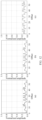
- Correlation characteristics corresponding to the pilot sequence are shown in FIG. 12 .
- (a) in FIG. 12 shows a periodic autocorrelation result of the pilot sequence in the X polarization direction
- (b) in FIG. 12 shows a periodic autocorrelation result of the pilot sequence in the Y polarization direction
- (c) in FIG. 12 shows a periodic cross-correlation result of the pilot sequence in the X and Y polarization directions.
- a sidelobe value of a periodic autocorrelation function of the symbol sequence in the two polarization directions is not greater than 0.177 (normalized amplitude)
- a periodic cross-correlation function value of the symbol sequence in the two polarization directions is not greater than 0.197 (normalized amplitude).
- a value of A does not affect a normalized amplitude value of a correlation function, that is, the correlation characteristics are independent of a modulation format used. Therefore, when the correlation characteristics of the sequence are verified in this embodiment and the subsequent embodiments, the value of A is not limited, which is not repeated in this application.
- a frame overhead of the super-frame structure provided in this embodiment of this application is as low as 1.79%, and the designed sequence has relatively good autocorrelation and cross-correlation characteristics.
- the frame alignment word sequence can further meet direct current balance, and the training sequence and the pilot sequence can also be combined together to meet direct current balance, which helps improve quality of a signal restored at the receiver end.
- the receiver end Based on received signals in the two polarization directions, the receiver end performs signal processing by using the frame alignment word sequence, the training sequence, and the pilot sequence, to restore the signals.
- the polarization directions can be distinguished by calculating correlation values between the received signals in the two polarization directions and sequence symbols of the training sequence in the X and Y polarizations respectively, and sub-frame alignment may be performed; super-frame alignment is performed by using the frame alignment word sequence; and carrier phase recovery is performed by using the pilot signal.
- the three symbol sequences in this embodiment may be represented in the form of bit sequences.
- bit sequences may be shown in the following tables, where bi to bs are the corresponding bits in FIG. 7 and FIG. 8 .
- Abit sequence corresponding to the frame alignment word sequence is as follows: Index DP-16QAM DP-QPSK Index DP-16QAM DP-QPSK b 1 b 2 b 3 b 4 b 5 b 6 b 7 b 8 b 1 b 2 b 3 b 4 b 1 b 2 b 3 b 4 b 5 b 6 b 7 b 8 b 1 b 2 b 3 b 4 b 5 b 6 b 7 b 8 b 1 b 2 b 3 b 4 1 1010 0000 11 00 13 1000 1000 10 10 10 2 1000 1000 1000 10 10 14 1000 1000 10 10 3 1010 0000 11 00 15 0010 0010 01 01 4 0010 0010 01 01 16 0000 1010 00 11 5 1010 0000 11 00 17 0000 1010 00 11 6 0000 1010 00 11 18 1000 1000 10 10 7 1000 1000 10 10 19 1010 0000 11 00 8 1000 1000 10 10 20 0000 1010 00 11 9 0010
- a bit sequence corresponding to the training sequence is as follows: Index DP-16QAM DP-QPSK Index DP-16QAM DP-QPSK b 1 b 2 b 3 b 4 b 5 b 6 b 7 b 8 b 1 b 2 b 3 b 4 b 1 b 2 b 3 b 4 b 5 b 6 b 7 b 8 b 1 b 2 b 3 b 4 b 5 b 6 b 7 b 8 b 1 b 2 b 3 b 4 1 0000 0010 00 01 4 0000 1010 00 11 2 0010 0010 01 01 5 1000 1000 10 10 3 1010 0000 11 00 6 1010 1000 11 10
- a bit sequence corresponding to the pilot sequence is as follows: Index DP-16QAM DP-QPSK Index DP-16QAM DP-QPSK b 1 b 2 b 3 b 4 b 5 b 6 b 7 b 8 b 1 b 2 b 3 b 4 b 1 b 2 b 3 b 4 b 5 b 6 b 7 b 8 b 1 b 2 b 3 b 4 b 5 b 6 b 7 b 8 b 1 b 2 b 3 b 4 1 0010 0000 01 00 30 0000 0010 00 01 2 0000 0010 00 01 31 0010 0000 01 00 3 0010 0000 01 00 32 0000 0010 00 01 4 1000 1010 10 11 33 1000 1010 10 11 5 1010 1000 11 10 34 0000 0010 00 01 6 1000 1010 10 11 35 0000 0010 00 01 7 1010 1000 11 10 36 1010 1000 11 1010 1000 11 10 10 10 10 37 0000 0010
- spectral flatness characteristics of a super-frame in different modulation formats are further simulated.
- FIG. 13 provides a spectrum diagram of a super-frame structure shown in FIG. 9 that includes 300 super-frames for DP-16QAM.
- FIG. 13 is a spectrum diagram of a random DP-16QAM signal with the same length
- FIG. 14 provides a spectrum diagram of the super-frame structure shown in FIG. 9 that includes 300 super-frames for DP-QPSK.
- FIG. 14 is a spectrum diagram of a random DP-QPSK signal with the same length.
- Embodiment 2 This embodiment of this application further provides a specific super-frame format. Symbols before framing are obtained through CFEC encoding. A quantity of the symbols is 175616.
- the following table lists parameters N SF , N TS , N PS , N FAW , N RES , N S , N F , and OH corresponding to the super-frame, and the like.
- a super-frame structure thereof is shown in FIG. 15 .
- the super-frame includes 43 sub-frames, and each sub-frame includes 4160 symbols, as shown in (a) in FIG. 15 .
- the 1 st sub-frame is shown in (b) in FIG. 15 , including 10 training symbols, 22 frame alignment word symbols, and 60 reserved symbols.
- the 2 nd to 43 rd sub-frames each also have 10 training symbols, as shown in (c) in FIG. 15 .
- the 1 st symbol in every 64 symbols is a pilot symbol.
- a frame alignment word sequence with a length of 22 is one item in Table 6.
- a training sequence with a length of 10 may be one item in Table 33.
- a pilot sequence with a length of 65, according to the super-frame structure, is one item in Table 11-1 or Table 11-2 of which the 1 st symbol is the same as the 1 st symbol of the used training sequence.
- the frame alignment word sequence with a symbol length of 22 is the following sequence: Polarization Frame alignment word sequence X A-Aj, A-Aj, A+Aj, -A-Aj, A+Aj, A+Aj, A+Aj, A+Aj, -A+Aj, A-Aj, A-Aj, -A-Aj, A-Aj, A+Aj, -A+Aj, -A+Aj, -A+Aj, A+Aj, -A-Aj, -A+Aj, A+Aj, -A-Aj, -A+Aj, A+Aj, -A-Aj, -A+Aj, A+Aj, -A-Aj, -A+Aj,
- Correlation characteristics corresponding to the frame alignment word sequence are shown in FIG. 16 .
- (a) in FIG. 16 shows an aperiodic autocorrelation result of the frame alignment word sequence in the X polarization direction
- (b) in FIG. 16 shows an aperiodic autocorrelation result of the frame alignment word sequence in the Y polarization direction
- (c) in FIG. 16 shows an aperiodic cross-correlation result of the frame alignment word sequence in the X and Y polarization directions.
- a sidelobe value of an aperiodic autocorrelation function of the symbol sequence in the two polarization directions is not greater than 0.182 (normalized amplitude), and an aperiodic cross-correlation function value of the symbol sequence in the two polarization directions is not greater than 0.188 (normalized amplitude).
- the frame alignment word sequence with a length of 22 may be an existing symbol sequence, for example, a sequence used for OIF-400ZR.
- the sequence has relatively poor cross-correlation in the X polarization and the Y polarization, and the receiver end needs to use more symbols to ensure a sufficiently low alignment error probability during alignment.
- the training sequence with a symbol length of 10 is the following sequence: Polarization Training sequence X -A+Aj, A-Aj, -A+Aj, -A+Aj, -A-Aj, -A-Aj, A+Aj, A+Aj, A-Aj, A-Aj Y -A-Aj, -A-Aj, -A+Aj, A-Aj, A+Aj, A+Aj, -A-Aj, A+Aj, -A-Aj, A+Aj, -A+Aj, A-Aj, A-A+Aj, A-Aj
- Correlation characteristics corresponding to the training sequence are shown in FIG. 17 .
- (a) in FIG. 17 shows an aperiodic autocorrelation result of the training sequence in the X polarization direction
- (b) in FIG. 17 shows an aperiodic autocorrelation result of the training sequence in the Y polarization direction
- (c) in FIG. 17 shows an aperiodic cross-correlation result of the training sequence in the X and Y polarization directions.
- a sidelobe value of an aperiodic autocorrelation function of the symbol sequence in the two polarization directions is not greater than 0.283 (normalized amplitude), and an aperiodic cross-correlation function value of the symbol sequence in the two polarization directions is not greater than 0.283 (normalized amplitude).
- the pilot sequence with a symbol length of 65 is the following sequence: Polarization Pilot sequence X -A+Aj, A-Aj, -A+Aj, -A+Aj, A+Aj, A+Aj, A-Aj, A+Aj, -Aj, -A+Aj, -A+Aj, -A+Aj, A-Aj, -A-Aj, A-Aj, A+Aj, A+Aj, -A-Aj, A-Aj, -A+Aj, -A-Aj, -A-Aj, A-Aj, A+Aj, A-Aj, -A+Aj, -A-Aj, A-Aj, A+Aj, A-Aj, -A+Aj, -A-Aj, A-Aj, -A+Aj, A+Aj, A-Aj, -A-Aj, A-Aj, -A+Aj, A+
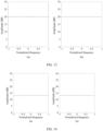
- Correlation characteristics corresponding to the pilot sequence are shown in FIG. 18 .
- (a) in FIG. 18 shows a periodic autocorrelation result of the pilot sequence in the X polarization direction
- (b) in FIG. 18 shows a periodic autocorrelation result of the pilot sequence in the Y polarization direction
- (c) in FIG. 18 shows a periodic cross-correlation result of the pilot sequence in the X and Y polarization directions.
- a sidelobe value of a periodic autocorrelation function of the symbol sequence in the two polarization directions is not greater than 0.161 (normalized amplitude)
- a periodic cross-correlation function value of the symbol sequence in the two polarization directions is not greater than 0.173 (normalized amplitude).
- a frame overhead of the super-frame structure provided in this embodiment of this application is also as low as 1.86%, and the designed sequence has relatively good autocorrelation and cross-correlation characteristics.
- the frame alignment word sequence can further meet direct current balance, and the training sequence and the pilot sequence can also be combined together to meet direct current balance, which helps improve quality of a signal restored at the receiver end.
- spectral flatness characteristics of a super-frame are further simulated.
- a result is shown in FIG. 19 , which uses a spectrum diagram of the super-frame structure shown in FIG. 15 that includes 300 super-frames. It can be learned that there is a very small difference between spectral flatness characteristics of the super-frame structure provided in this embodiment and spectral flatness characteristics of a random modulation signal with the same length, as well as very good flatness.
- Embodiment 3 This embodiment of this application further provides a specific super-frame format. Symbols before framing are obtained through CFEC encoding. A quantity of the symbols is 175616.
- the following table lists parameters N SF , N TS , N PS , N FAW , N RES , N S , N F , and OH corresponding to the super-frame, and the like.
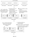
- a super-frame structure thereof is shown in FIG. 20 .
- the super-frame includes 50 sub-frames, and each sub-frame includes 3584 symbols, as shown in (a) in FIG. 20 .
- the 1 st sub-frame is shown in (b) in FIG. 20 , including 15 training symbols, 22 frame alignment word symbols, and 62 reserved symbols.
- the 2 nd to 50 th sub-frames each also have 15 training symbols, as shown in (c) in FIG. 20 .
- the 1 st symbol in every 64 symbols is a pilot symbol.
- a frame alignment word sequence with a length of 22 is one item in Table 6.
- a training sequence with a length of 15 may be one item in Table 42.
- a pilot sequence with a length of 56, according to the super-frame structure, is one item in Table 9-1 or Table 9-2 of which the 1 st symbol is the same as the 1 st symbol of the used training sequence.
- Table 9-1 or Table 9-2 the 1 st symbol is the same as the 1 st symbol of the used training sequence.
- the training sequence with a symbol length of 15 uses the following sequence: Polarization Training sequence X -A+Aj, A-Aj, -A-Aj, -A-Aj, A+Aj, -A+Aj, A-Aj, A+Aj, A-Aj, -A+Aj, A+Aj, A-Aj, -A+Aj, -A+Aj, -A-Aj Y -A-Aj, -A-Aj, -A+Aj, A-Aj, A+Aj, -A+Aj, -A-Aj, A+Aj, -A-Aj, A+Aj, -A-Aj, A+Aj, -A-Aj, A+Aj, A-A-Aj, A+Aj, A-A-Aj, A+Aj, A-A-Aj, A+Aj, A-A-Aj, A+Aj, A-A-Aj,
- Correlation characteristics corresponding to the training sequence are shown in FIG. 21 .
- (a) in FIG. 21 shows an aperiodic autocorrelation result of the training sequence in the X polarization direction
- (b) in FIG. 21 shows an aperiodic autocorrelation result of the training sequence in the Y polarization direction
- (c) in FIG. 21 shows an aperiodic cross-correlation result of the training sequence in the X and Y polarization directions.
- a sidelobe value of an aperiodic autocorrelation function of the symbol sequence in the two polarization directions is not greater than 0.211 (normalized amplitude), and an aperiodic cross-correlation function value of the symbol sequence in the two polarization directions is not greater than 0.211 (normalized amplitude).
- the pilot sequence with a symbol length of 56 uses the following sequence: Polarization Pilot sequence X -A+Aj, A+Aj, -A+Aj, A+Aj, -A-Aj, A+Aj, A+Aj, -A-Aj, -A-Aj, A-Aj, -A-Aj, -A-Aj, A-Aj, -A+Aj, - A+Aj, -A+Aj, -A+Aj, -A-Aj, A+Aj, -A-Aj, -A+Aj, -A-Aj, A-Aj, -A-Aj, A-Aj, A+Aj, -Aj, -A-Aj, A-Aj, A+Aj, -A+Aj, A-Aj, -Aj, A-Aj, A+Aj, -A+Aj, A-Aj, A-Aj, -Aj,
- Correlation characteristics corresponding to the pilot sequence are shown in FIG. 22 .
- (a) in FIG. 22 shows a periodic autocorrelation result of the pilot sequence in the X polarization direction
- (b) in FIG. 22 shows a periodic autocorrelation result of the pilot sequence in the Y polarization direction
- (c) in FIG. 22 shows a periodic cross-correlation result of the pilot sequence in the X and Y polarization directions.
- a sidelobe value of a periodic autocorrelation function of the symbol sequence in the two polarization directions is not greater than 0.183 (normalized amplitude)
- a periodic cross-correlation function value of the symbol sequence in the two polarization directions is not greater than 0.203 (normalized amplitude).
- a frame overhead of the super-frame structure provided in this embodiment of this application is also as low as 2.03%; the training sequence is relatively long, so that the receiver end performs frame alignment; and the designed sequence has relatively good autocorrelation and cross-correlation characteristics.
- the frame alignment word sequence can further meet direct current balance, and the training sequence and the pilot sequence can also be combined together to meet direct current balance, which helps improve quality of a signal restored at the receiver end.
- spectral flatness characteristics of a super-frame are further simulated.
- a result is shown in FIG. 23 , which uses a spectrum diagram of the super-frame structure shown in FIG. 20 that includes 300 super-frames. It can be learned that there is a very small difference between spectral flatness characteristics of the super-frame structure provided in this embodiment and spectral flatness characteristics of a random modulation signal with the same length, as well as very good flatness.
- Embodiment 4 This embodiment of this application provides a specific super-frame format. Symbols before framing are obtained through open FEC (Open FEC, OFEC) encoding. A quantity of the symbols is 172032.
- the following table lists parameters N SF , N TS , N PS , N FAW , N RES , N S , N F , and OH corresponding to the super-frame, and the like.
- N SF N PS N S N F OH N FAW N TS N RES 48 57 3648 175104 1.79% 24 6 72
- a super-frame structure thereof is shown in FIG. 24 .
- the super-frame includes 48 sub-frames, and each sub-frame includes 3648 symbols, as shown in (a) in FIG. 24 .
- the 1 st sub-frame is shown in (b) in FIG. 24 , including 6 training symbols, 24 frame alignment word symbols, and 72 reserved symbols.
- the 2 nd to 48 th sub-frames each also have 6 training symbols, as shown in (c) in FIG. 24 .
- the 1 st symbol in every 64 symbols is a pilot symbol.
- a frame alignment word sequence with a length of 24 is one item in Table 7.
- a training sequence with a length of 6 may be one item in Table 31.
- a pilot sequence with a length of 57, according to the super-frame structure, is one item in Table 10-1 or Table 10-2 of which the 1 st symbol is the same as the 1 st symbol of the used training sequence.
- the same frame alignment word sequence, training sequence, and pilot sequence as those in Embodiment 1 are used, and correlations thereof are respectively shown in FIG. 10 to FIG. 12 .
- spectral flatness characteristics of a super-frame are further simulated.
- a result is shown in FIG. 25 , which uses a spectrum diagram of the super-frame structure shown in FIG. 24 that includes 300 super-frames. It can be learned that there is a very small difference between spectral flatness characteristics of the super-frame structure provided in this embodiment and spectral flatness characteristics of a random modulation signal with the same length, as well as very good flatness.
- Embodiment 5 This embodiment of this application provides a specific super-frame format. Symbols before framing are obtained through CFEC encoding. A quantity of the symbols is 175616.
- the following table lists parameters N SF , N TS , N PS , N FAW , N RES , N S , N F , and OH corresponding to the super-frame, and the like.
- a super-frame structure thereof is shown in FIG. 26 .
- the super-frame includes 50 sub-frames, and each sub-frame includes 3600 symbols, as shown in (a) in FIG. 26 .
- the 1 st sub-frame is shown in (b) in FIG. 26 , including 12 training symbols, 22 frame alignment word symbols, and 62 reserved symbols.
- the 2 nd to 50 th sub-frames each also have 12 training symbols, as shown in (c) in FIG. 26 .
- the 1 st symbol in every 48 symbols is a pilot symbol.
- a frame alignment word sequence with a length of 22 is one item in Table 6.
- a training sequence with a length of 12 may be one item in Table 34.
- a pilot sequence with a length of 75, according to the super-frame structure, is one item in Table 26 of which the 1 st symbol is the same as the 1 st symbol of the used training sequence. For example, considering that the frame alignment word sequence with a symbol length of 22 uses the same sequence as that in Embodiment 2, a correlation simulation result corresponding to the frame alignment word sequence is shown in FIG. 16 .
- the training sequence with a symbol length of 12 uses the following sequence: Polarization Training sequence X -A+Aj, -A-Aj, -A-Aj, A+Aj, A-Aj, A+Aj, A+Aj, -A+Aj, A-Aj, A-Aj, -A+Aj, -A-Aj Y -A-Aj, -A+Aj, A-Aj, -A+Aj, -A-Aj, A-Aj, -A-Aj, -A+Aj, A+Aj, A+Aj, A-Aj, A+Aj, A-Aj, A+Aj, A+Aj, A-Aj, A+Aj
- Correlation characteristics corresponding to the training sequence are shown in FIG. 27 .
- (a) in FIG. 27 shows an aperiodic autocorrelation result of the training sequence in the X polarization direction
- (b) in FIG. 27 shows an aperiodic autocorrelation result of the training sequence in the Y polarization direction
- (c) in FIG. 27 shows an aperiodic cross-correlation result of the training sequence in the X and Y polarization directions.
- a sidelobe value of an aperiodic autocorrelation function of the symbol sequence in the two polarization directions is not greater than 0.251 (normalized amplitude), and an aperiodic cross-correlation function value of the symbol sequence in the two polarization directions is not greater than 0.251 (normalized amplitude).
- the pilot sequence with a symbol length of 75 uses the following sequence: Polarization Pilot sequence X -A+Aj, -A-Aj, A+Aj, A-Aj, A-Aj, A+Aj, -A+Aj, -A+Aj, A+Aj, A-Aj, -A+Aj, -A+Aj, A+Aj, -A+Aj, -A+Aj, -A-Aj, A-Aj, -A+Aj, -A-Aj, A+Aj, -A+Aj, A+Aj, -A-Aj, A-Aj, -A+Aj, A+Aj, -A-Aj, A+Aj, A+Aj, -A-Aj, A+Aj, A+Aj, -A-Aj, A+Aj, A+Aj, -A-Aj, A+Aj, A+Aj, -A-Aj,
- Correlation characteristics corresponding to the pilot sequence are shown in FIG. 28 .
- (a) in FIG. 28 shows a periodic autocorrelation result of the pilot sequence in the X polarization direction
- (b) in FIG. 28 shows a periodic autocorrelation result of the pilot sequence in the Y polarization direction
- (c) in FIG. 28 shows a periodic cross-correlation result of the pilot sequence in the X and Y polarization directions.
- a sidelobe value of a periodic autocorrelation function of the symbol sequence in the two polarization directions is not greater than 0.150 (normalized amplitude)
- a periodic cross-correlation function value of the symbol sequence in the two polarization directions is not greater than 0.168 (normalized amplitude).
- a frame overhead of the super-frame structure provided in this embodiment of this application is also as low as 2.50%, and the designed sequence has relatively good autocorrelation and cross-correlation characteristics.
- the frame alignment word sequence can further meet direct current balance, and the training sequence and the pilot sequence can also be combined together to meet direct current balance, which helps improve quality of a signal restored at the receiver end.
- spectral flatness characteristics of a super-frame are further simulated.
- a result is shown in FIG. 29 , which uses a spectrum diagram of the super-frame structure shown in FIG. 26 that includes 300 super-frames. It can be learned that there is a very small difference between spectral flatness characteristics of the super-frame structure provided in this embodiment and spectral flatness characteristics of a random modulation signal with the same length, as well as very good flatness.
- Embodiment 6 This embodiment of this application provides a specific super-frame format. Symbols before framing are obtained through OFEC encoding. A quantity of the symbols is 172032. The following table lists parameters N SF , N TS , N PS , N FAW , N RES , N S , N F , OH, and the like corresponding to the super-frame. N SF N PS N S N F OH N FAW N TS N RES 49 75 3600 176400 2.54% 22 12 132
- a super-frame structure thereof is shown in FIG. 30 .
- the super-frame includes 49 sub-frames, and each sub-frame includes 3600 symbols, as shown in (a) in FIG. 30 .
- the 1 st sub-frame is shown in (b) in FIG. 30 , including 12 training symbols, 22 frame alignment word symbols, and 132 reserved symbols.
- the 2 nd to 49 th sub-frames each also have 12 training symbols, as shown in (c) in FIG. 30 .
- the 1 st symbol in every 48 symbols is a pilot symbol.
- a frame alignment word sequence with a length of 22 is one item in Table 6.
- a training sequence with a length of 12 may be one item in Table 34.
- a pilot sequence with a length of 75, according to the super-frame structure, is one item in Table 26 of which the 1 st symbol is the same as the 1 st symbol of the used training sequence.
- the same frame alignment word sequence, training sequence, and pilot sequence as those in Embodiment 5 are used, and correlations thereof are respectively shown in FIG. 16 , FIG. 27 , and FIG. 28 .
- a frame overhead of the super-frame structure provided in this embodiment of this application is also as low as 2.54%, and the designed sequence has relatively good autocorrelation and cross-correlation characteristics.
- the frame alignment word sequence can further meet direct current balance, and the training sequence and the pilot sequence can also be combined together to meet direct current balance, which helps improve quality of a signal restored at the receiver end.
- spectral flatness characteristics of a super-frame are further simulated.
- a result is shown in FIG. 31 , which uses a spectrum diagram of the super-frame structure shown in FIG. 30 that includes 300 super-frames. It can be learned that there is a very small difference between spectral flatness characteristics of the super-frame structure provided in this embodiment and spectral flatness characteristics of a random modulation signal with the same length, as well as very good flatness.
- an embodiment of this application further provides another transmission method for optical communication. As shown in FIG. 32 , the transmission method includes the following steps.
- a transmitting device generates a super-frame including a plurality of sub-frames, each of which includes training symbols and pilot symbols, where in one polarization direction, there is one symbol that is both a training symbol and a pilot symbol, and each of the training symbols and the pilot symbols is one of -A-Aj, -A+Aj, A-Aj, and A+Aj, A being a real number; in each sub-frame, in the one polarization direction, the pilot symbols are generated based on a target polynomial and a seed, there are N PS pilot symbols combined with N TS training symbols to achieve direct current balance, N TS is a quantity of the training symbols in each sub-frame in one polarization direction, and N TS +N PS is an odd number; and the target polynomial is one item in the following Table X-1.
- the transmitting device transmits the super-frame, and correspondingly, a receiving device receives the super-frame including the plurality of sub-frames.
- the receiving device decodes the received super-frame.
- a value of A is determined by a modulation format used when a symbol is generated, which can be understood by referring to the corresponding content in embodiments of FIG. 4 and FIG. 5A .
- the pilot symbols and the training symbols, -A-Aj, -A+Aj, A-Aj, and A+Aj may not be symbols in a constellation diagram of the used modulation format, and may be four symbols in a middle area between the outermost four symbols and the innermost four symbols in the constellation diagram.
- the training symbols and the pilot symbols have fair noise and sensitivity, but have a relatively low peak-to-average power ratio.
- values of the 16 symbols in the 16QAM constellation diagram are ⁇ 1 ⁇ 1j, ⁇ 1 + 3j, ⁇ 3 ⁇ 1j, ⁇ 3 + 3j ⁇ , and a value of the real number A meets 1 ⁇ A ⁇ 3. More specifically, as shown in FIG. 5B , the outermost four symbols in the constellation diagram are 3 + 3j, 3 - 3j, -3 + 3j, and -3 - 3j, and the innermost four symbols in the constellation diagram are 1 + 1j, 1 - 1j, -1 + 1j, and -1 - 1j.
- the values of the pilot symbols and the training symbols, -A-Aj, -A+Aj, A-Aj, and A+Aj may be four symbols in the middle area between the outermost four symbols and the innermost four symbols in the 16QAM constellation diagram.
- a specific value of the real number A may be selected according to an actual application scenario, so that the peak-to-average power ratio, noise, and sensitivity of the training symbols and the pilot symbols have a good compromise.
- the real number A 5
- the values of the pilot symbols and the training symbols are ⁇ 5 ⁇ 5 j , ⁇ 5 + 5 j , 5 ⁇ 5 j , 5 + 5 j .
- the 16 symbols in the 16QAM constellation diagram are subjected to power normalization and have values of ⁇ 1 / 10 ⁇ 1 / 10 j , ⁇ 1 / 10 ⁇ 3 / 10 j , ⁇ 3 / 10 ⁇ 1 / 10 j , ⁇ 3 / 10 ⁇ 3 / 10 j , the value of the real number A meets 1 / 10 ⁇ A ⁇ 3 / 10 .
- the real number A 2 / 2
- the values of the pilot symbols and the training symbols are ⁇ 2 / 2 ⁇ 2 , 2 j , ⁇ 2 / 2 + 2 / 2 j , 2 / 2 ⁇ 2 / 2 j , 2 / 2 + 2 / 2 j .
- polarization directions there are two polarization directions, and the two polarization directions are orthogonal to each other.
- the two polarization directions may also be described by a polarization 1 and a polarization 2.
- a sum of quantities of training symbols and pilot symbols included in one sub-frame is N TS +N PS -1. Because one symbol is both a training symbol and a pilot symbol, the sum of quantities is not N TS +N PS , and is one less than the sum of quantities of the two types of symbols.
- the pilot symbols are generated based on the target polynomial and the seed.
- the target polynomial is any item in the foregoing Table X-1, and the target polynomial and the corresponding seed can meet that a combination of the generated N PS pilot symbols and N TS training symbols achieves direct current balance, that is, in one polarization direction, a sum of real parts of complex numbers corresponding to the training symbols and the pilot symbols in one sub-frame is 0, and a sum of imaginary parts thereof is also 0, which helps a receiver end restore a signal better, and improves quality of the signal at the receiver end.
- a structure of the super-frame provided in this embodiment of this application can be understood by referring to the corresponding content in (a) in FIG. 6 to (c) in FIG. 6 , and details are not described herein again.
- Table X-2 lists parameters N SF , N PS , N TS , N S , N F , N FAW , N RES , and OH corresponding to the super-frame, and the like.
- Table X-2 N SF N PS N S N F OH N TS N FAW + N RES 24 114 7296 175104 1.79% 11 96
- a super-frame structure thereof is shown in (a) in FIG. 33 .
- the super-frame includes 24 sub-frames, and each sub-frame includes 7296 symbols.
- the 2 nd to 24 th sub-frames each also have 11 training symbols.
- the 1 st symbol in every 64 symbols is a pilot symbol
- each sub-frame includes 114 pilot symbols.
- a sequence of 22 frame alignment word symbols can be understood by referring to the following Table X-3: Table X-3 Polarization Sequence of frame alignment word symbols Polarization 1 A - Aj, A+Aj, A + Aj, A+Aj, A - Aj, A - Aj, -A - Aj, A + Aj, -A - Aj, -A+Aj, -A+Aj, A - Aj, -A -Aj, -A + Aj, A + Aj, -A-Aj, A-Aj, -A + Aj, A+Aj, -A-Aj, -A+Aj Polarization2 A + Aj, -A + Aj, -A - Aj, -A + Aj, A- Aj, A + Aj, A- Aj, A + Aj, A-A-Aj, -A+Aj Polar
- a sequence of 11 training symbols can be understood by referring to the following Table X-4: Table X-4 Polarization Sequence of training symbols Polarization 1 -A+Aj, A+Aj, -A + Aj, A+Aj, -A - Aj, A + Aj, -A - Aj, -A - Aj, A + Aj, A - Aj, A - Aj Polarization 2 -A - Aj, -A - Aj, A -A + Aj, -A + Aj, A+Aj, -A - Aj, -A + Aj, A -Aj, A+Aj, A -Aj, A+Aj, A - Aj, A+Aj, A - Aj, A+Aj, A - Aj, A- Aj
- the 114 pilot symbols are determined based on the target polynomial and the corresponding seed (seed).
- the target polynomial is a 10-order polynomial
- the 10-order polynomial may be expressed as: x 10 + a 9 ⁇ x 9 + a 8 ⁇ x 8 + a 7 ⁇ x 7 + a 6 ⁇ x 6 + a 5 ⁇ x 5 + a 4 ⁇ x 4 + a 3 ⁇ x 3 + a 2 ⁇ x 2 + a 1 ⁇ x + 1 where a value of a 9 ... a 1 may be 0 or 1.
- a pilot symbol generation structure can be understood by referring to FIG. 34 .
- a seed may be expressed as m 9 , m 8 , m 7 , m 6 , m 5 , m 4 , m 3 , m 2 , m 1 , m 0 in the binary form.
- the seed may also be expressed in the hexadecimal or decimal form, and when computed with the target polynomial, the seed needs to be converted into a binary form. For example, 0110111000 is expressed as 0x1B8 in the hexadecimal form, or is expressed as 440 in the decimal form.
- the same target generator polynomial may be used for pilot symbols in two orthogonal polarization directions.
- pilot symbols output in the two polarization directions are not completely the same.
- a bit sequence with a continuous length of 228, b 0 , b 1 , b 2 , ... b 227 is obtained based on the target polynomial and the seed. Every two consecutive bits in the bit sequence b 0 , b 1 , b 2 , ... b 227 are mapped to one symbol, where b 2 t and b 2 t +1 are mapped to one symbol (2 b 2 t - 1)A + (2 b 2 t +1 - 1)Aj, 0 ⁇ t ⁇ 114.
- the symbols (2 b 2 t - 1)A + (2 b 2 t +1 - 1)Aj may not be symbols in a constellation diagram of the used modulation format, and may be four symbols in a middle area between the outermost four symbols and the innermost four symbols in the constellation diagram of the used modulation format.
- the training symbols and the pilot symbols have fair noise and sensitivity, but have a relatively low peak-to-average power ratio.
- values of the 16 symbols in the 16QAM constellation diagram are ⁇ 1 ⁇ 1j, ⁇ 1 ⁇ 3j, ⁇ 3 ⁇ 1j, ⁇ 3 ⁇ 3j 1, and a value of the real number A meets 1 ⁇ A ⁇ 3.
- a specific value of the real number A may be selected according to an actual application scenario, so that the peak-to-average power ratio, noise, and sensitivity of the training symbols and the pilot symbols have a good compromise.
- the real number A 5
- the values of the pilot symbols and the training symbols are ⁇ 5 ⁇ 5 j , ⁇ 5 + 5 j , 5 ⁇ 5 j , 5 + 5 j .
- the 16 symbols in the 16QAM constellation diagram are subjected to power normalization and have values of ⁇ 1 10 ⁇ 1 10 j , ⁇ 1 10 ⁇ 3 10 j , ⁇ 3 10 ⁇ 1 10 j , ⁇ 3 10 ⁇ 3 10 j
- the value of the real number A meets 1 10 ⁇ A ⁇ 3 10 .
- the real number A 2 2
- the values of the pilot symbols and the training symbols are ⁇ 2 2 ⁇ 2 2 j , ⁇ 2 2 + 2 2 j , 2 2 ⁇ 2 2 j , 2 2 + 2 2 j .
- the target polynomial and the seed may be determined by designing values of the coefficients a 9 ... a 1 in the polynomial, so that a symbol sequence of the generated pilot symbols in the X polarization or the Y polarization has relatively good autocorrelation characteristics, and symbol sequences in the two polarizations have relatively good cross-correlation characteristics.
- a normalized amplitude of a sidelobe value of a periodic autocorrelation function of a symbol sequence in the two polarization directions is not greater than a preset value T0
- a normalized amplitude of a periodic cross-correlation function value of the symbol sequence in the two polarization directions is not greater than a preset value T1.
- a normalized amplitude of a sidelobe value of a periodic autocorrelation function of pilot symbols in the same polarization direction is not greater than 0.2
- Table X-5 Index Target polynomial Seed in the direction of polarization 1 Seed in the direction of polarization 2 1 x 10 + x 9 + x 8 + x 7 + x 6 +1 0x122 0x0E4 2 x 10 + x 9 + x 8 + x 7 + x 6 +1 0x122 0x06C 3 x 10 + x 9 + x 8 + x 7 + x 6 +1 0x362 0x1C4 4 x 10 + x 9 + x 8 + x 7 + x 6 +1 0x362 0x0DC 5 x 10 + x 9 + x 8 + x 7 + x 6 +1 0x31A 0x0E4 6 x 10 + x 9 + x 8 + x 7 + x 6 +1 0x31A 0x06C 7 x 10 + x 9 + x 8 + x 7 + x 6 +1 0x046 0x384 8
- Table X-6 is a subset of Table X-5
- quantities of -A-Aj, -A+Aj, A-Aj, and A+Aj in one polarization direction are all 31.
- Table X-6 Index Target polynomial Seed in the direction of polarization 1 Seed in the direction of polarization 2 1 x 10 + x 9 + x 8 + x 7 + x 6 +1 0x046 0x384 2 x 10 + x 9 + x 8 + x 7 + x 6 +1 0x046 0x3C4 3 x 10 + x 9 + x 6 + x 3 +1 0x076 0x07C 4 x 10 + x 8 + x 7 + x 4 + x 3 +1 0x1A2 0x330 5 x 10 + x 8 + x 7 + x 4 + x 3 +1 0x2E6 0x330 6 x 10 + x 8 + x 7 + x 2 + x +1 0x226 0x3DC 7 x 10 + x 9 + x 6 + x 3 + x 2 + x +1 0x13A 0x330 8 x 10
- a sequence generated when the target polynomial is a primitive polynomial generally has relatively good randomness, and that more non-zero terms of the target polynomial indicate more complex implementation
- the target polynomial uses the primitive polynomial and there are no more than 5 non-zero terms of the target polynomial
- the target polynomial and hexadecimal seeds in two polarization directions are one row in the following Table X-7
- a normalized amplitude of a sidelobe value of a periodic autocorrelation function of pilot symbols in the same polarization direction is not greater than 0.25
- a normalized amplitude of a periodic cross-correlation function value of pilot symbols in different polarization directions is not greater than 0.25.
- the input polarization seed is 0x34E, which is 1101001110 after being converted into a binary sequence, that is, values of m 9 to m 0 .
- a pilot symbol in the X polarization direction is A-Aj.
- a pilot symbol in the X polarization direction is -A-Aj.
- a pilot symbol in the X polarization direction is A+Aj.
- a pilot symbol in the X polarization direction is -A+Aj.
- the input polarization seed is 0x084, which is 0010000100 after being converted into a binary sequence, that is, values of m 9 to m 0 .
- a pilot symbol in the Y polarization direction is A-Aj.
- a pilot symbol in the Y polarization direction is -A-Aj.
- a pilot symbol in the Y polarization direction is A+Aj.
- a pilot symbol in the Y polarization direction is -A+Aj.
- Table X-8 Polarization direction Pilot symbol Polarization 1 -A+Aj, A+Aj, -A-Aj, A-Aj, A+Aj, -A+Aj, A-Aj, A+Aj, -A-Aj, -A-Aj, A+Aj, -A-Aj, -A+Aj, -A-Aj, -A+Aj, -A-Aj, -A+Aj, -A-Aj, -A+Aj, -A-Aj, -A+Aj, A-Aj, -A+Aj, A-Aj, -A+Aj, A-Aj, A+Aj, A-Aj, A-Aj, A+Aj, A-A-Aj, -A+Aj, A-Aj, -A+Aj, A-Aj, -A+Aj, A-Aj, A+Aj, A-Aj, A-A+A
- FIG. 36 shows correlation characteristics corresponding to the pilot symbols.
- (a) in FIG. 36 shows a periodic autocorrelation result of the sequence of pilot symbols in the X polarization direction
- (b) in FIG. 36 shows a periodic autocorrelation result of the sequence of pilot symbols in the Y polarization direction
- (c) in FIG. 36 shows a periodic cross-correlation result of the sequence of pilot symbols in the X and Y polarization directions.
- a normalized amplitude of a sidelobe value of a periodic autocorrelation function of a symbol sequence in the two polarization directions is not greater than 0.167, and a normalized amplitude of a sidelobe value of a periodic cross-correlation function of the symbol sequence in the two polarization directions is not greater than 0.202.
- a frame overhead of the super-frame structure provided in this embodiment of this application is also as low as 1.79%, and the sequence of pilot symbols has relatively good autocorrelation and cross-correlation characteristics.
- the training symbols and the pilot symbols can also be combined together to meet direct current balance, which helps the receiver end restore a signal, and improves quality of the restored signal.
- the input polarization seed is 0x0BE, which is 0010111110 after being converted into a binary sequence, that is, values of m 9 to m 0 .
- a pilot symbol in the X polarization direction is A-Aj.
- a pilot symbol in the X polarization direction is -A-Aj.
- a pilot symbol in the X polarization direction is A+Aj.
- a pilot symbol in the X polarization direction is -A+Aj.
- the input polarization seed is 0x1B8, which is 0110111000 after being converted into a binary sequence, that is, values of m 9 to m 0 .
- a pilot symbol in the Y polarization direction is A-Aj.
- a pilot symbol in the Y polarization direction is -A-Aj.
- a pilot symbol in the Y polarization direction is A+Aj.
- a pilot symbol in the Y polarization direction is -A+Aj.
- Table X-9 Polarization direction Pilot symbol Polarization 1 -A+Aj, A+Aj, A+Aj, -A+Aj, -A-Aj, -A+Aj, -A-Aj, -A+Aj, -A+Aj, A-Aj, A+Aj, A-Aj, -A-Aj, -A+Aj, -A+Aj, A-Aj, -A+Aj, A-Aj, -A-Aj, A+Aj, -A+Aj, A-Aj, -A-Aj, -A+Aj, A-Aj, -A+Aj, A-Aj, -A+Aj, -Aj, -A+Aj, -A-Aj, A-Aj, -A+Aj, -A-Aj, A-Aj, -A+Aj, -A-Aj, A-Aj, -A+Aj
- FIG. 38 shows correlation characteristics corresponding to the pilot symbols.
- (a) in FIG. 38 shows a periodic autocorrelation result of the sequence of pilot symbols in the X polarization direction
- (b) in FIG. 38 shows a periodic autocorrelation result of the sequence of pilot symbols in the Y polarization direction
- (c) in FIG. 38 shows a periodic cross-correlation result of the sequence of pilot symbols in the X and Y polarization directions.
- a normalized amplitude of a sidelobe value of a periodic autocorrelation function of a symbol sequence in the two polarization directions is not greater than 0.162, and a normalized amplitude of a sidelobe value of a periodic cross-correlation function of the symbol sequence in the two polarization directions is not greater than 0.185.
- a frame overhead of the super-frame structure provided in this embodiment of this application is also as low as 1.79%, and the designed sequence of pilot symbols has relatively good autocorrelation and cross-correlation characteristics.
- the training sequence and the sequence of pilot symbols can also be combined together to meet direct current balance, which helps the receiver end restore a signal, and improves quality of the restored signal.
- the corresponding content of the super-frame corresponding to the row indexed 9 in the foregoing Table 2 is described below.
- a super-frame structure thereof is shown in (a) in FIG. 39 .
- the super-frame includes 48 sub-frames, and each sub-frame includes 3648 symbols.
- the 2 nd to 48 th sub-frames each also have 6 training symbols.
- the 1 st symbol in every 64 symbols is a pilot symbol
- each sub-frame includes 57 pilot symbols.
- a sequence of 22 frame alignment word symbols can be understood by referring to the Table X-3. It is considered that a start symbol of the 6 training symbols needs to be the same as a start symbol of the 57 pilot symbols.
- a sequence of 22 frame alignment word symbols can be understood by referring to the Table X-3. It is considered that a start symbol of the 6 training symbols needs to be the same as a start symbol of the 57 pilot symbols.
- a sequence of 6 training symbols can be understood by referring to the following Table X-11: Table X-11 Polarization Sequence of training symbols Polarization 1 A-Aj, A+Aj, A+Aj, -A-Aj, -A-Aj, -A+Aj Polarization 2 A-Aj, -A-Aj, -A+Aj, A-Aj, A+Aj, -A+Aj
- the 57 pilot symbols are determined based on the target polynomial and the corresponding seed (seed).
- the structure for generating the pilot symbols based on the target polynomial and the seed can be understood by referring to the corresponding content in FIG. 34 .
- a bit sequence with a continuous length of 114, b 0 , b 1 , b 2 , ... b 113 is obtained based on the target polynomial and the seed. Every two consecutive bits in the bit sequence b 0 , b 1 , b 2 , ... b 113 are mapped to one symbol, where b 2 t and b 2 t +1 are mapped to one symbol ( 2b 2 t - 1)A + ( 2b 2 t +1 - 1)Aj.
- the symbols ( 2b 2 t - 1)A + ( 2b 2 t +1 - 1)Aj may not be symbols in a constellation diagram of the used modulation format, and may be four symbols in a middle area between the outermost four symbols and the innermost four symbols in the constellation diagram of the used modulation format.
- the training symbols and the pilot symbols have fair noise and sensitivity, but have a relatively low peak-to-average power ratio.
- values of the 16 symbols in the 16QAM constellation diagram are ⁇ 1 ⁇ 1j, ⁇ 1 ⁇ 3j, ⁇ 3 ⁇ 1j, ⁇ 3 ⁇ 3j ⁇ , and a value of the real number A meets 1 ⁇ A ⁇ 3.
- a specific value of the real number A may be selected according to an actual application scenario, so that the peak-to-average power ratio, noise, and sensitivity of the training symbols and the pilot symbols have a good compromise.
- the real number A V5
- the values of the pilot symbols and the training symbols are ⁇ 5 ⁇ 5 j , ⁇ 5 + 5 j , 5 ⁇ 5 j , 5 + 5 j .
- the 16 symbols in the 16QAM constellation diagram are subjected to power normalization and have values of ⁇ 1 10 ⁇ 1 10 j , ⁇ 1 10 ⁇ 3 10 j , ⁇ 3 10 ⁇ 1 10 j , ⁇ 3 10 ⁇ 3 10 j
- the value of the real number A meets 1 10 ⁇ A ⁇ 3 10 .
- the real number A 2 2
- the values of the pilot symbols and the training symbols are ⁇ 2 2 ⁇ 2 2 j , ⁇ 2 2 + 2 2 j , 2 2 ⁇ 2 2 j , 2 2 + 2 2 j .
- a normalized amplitude of a sidelobe value of a periodic autocorrelation function of pilot symbols in the same polarization direction is not greater than 0.23
- a normalized amplitude of a periodic cross-correlation function value of pilot symbols in different polarization directions is not greater than 0.23.
- Table X-12 Index Target polynomial Seed in one polarization direction Seed in the other polarization direction 1 x 10 + x 7 + x 3 + x +1 0x204 0x279 2 x 10 + x 7 + x 3 + x +1 0x0B1 0x3E9 3 x 10 + x 7 + x 3 + x +1 0x0B1 0x279
- the input polarization seed is 0x0B1, which is 0010110001 after being converted into a binary sequence, that is, values of m 9 to m 0 .
- a pilot symbol in the X polarization direction is A-Aj.
- a pilot symbol in the X polarization direction is -A-Aj.
- a pilot symbol in the X polarization direction is A+Aj.
- a pilot symbol in the X polarization direction is -A+Aj.
- the input polarization seed is 0x3E9, which is 1111101001 after being converted into a binary sequence, that is, values of m 9 to m 0 .
- a pilot symbol in the Y polarization direction is A-Aj.
- a pilot symbol in the Y polarization direction is -A-Aj.
- a pilot symbol in the Y polarization direction is A+Aj.
- a pilot symbol in the Y polarization direction is -A+Aj.
- Table X-13 Polarization direction Pilot symbol Polarization 1 A-Aj, -A-Aj, A+Aj, -A+Aj, -A-Aj, -A+Aj, A+Aj, -A-Aj, -A+Aj, A+Aj, A+Aj, A-Aj, -A-Aj, -A+Aj, A+Aj, A+Aj, -Aj, -A+Aj, A+Aj, -A+Aj, -A+Aj, -A+Aj, A-Aj, A+Aj, A-Aj, A+Aj, A-Aj, A+Aj, A-Aj, A+Aj, A-Aj, A+Aj, A-Aj, A+Aj, A-Aj, A+Aj, A-Aj, A+Aj, A-Aj, A+Aj, A-Aj, A+Aj, A-Aj, A+A
- FIG. 41 shows correlation characteristics corresponding to the pilot symbols.
- (a) in FIG. 41 shows a periodic autocorrelation result of the sequence of pilot symbols in the X polarization direction
- (b) in FIG. 41 shows a periodic autocorrelation result of the sequence of pilot symbols in the Y polarization direction
- (c) in FIG. 41 shows a periodic cross-correlation result of the sequence of pilot symbols in the X and Y polarization directions.
- a normalized amplitude of a sidelobe value of a periodic autocorrelation function of a symbol sequence in the two polarization directions is not greater than 0.206, and a normalized amplitude of a sidelobe value of a periodic cross-correlation function of the symbol sequence in the two polarization directions is not greater than 0.212.
- a frame overhead of the super-frame structure provided in this embodiment of this application is also as low as 1.79%, and the designed sequence of pilot symbols has relatively good autocorrelation and cross-correlation characteristics.
- the training sequence and the sequence of pilot symbols can also be combined together to meet direct current balance, which helps the receiver end restore a signal, and improves quality of the restored signal.
- an embodiment of this application further provides another transmission method for optical communication. As shown in FIG. 42 , the transmission method includes the following steps.
- a transmitting device generates a super-frame including a plurality of sub-frames, where the sub-frame includes training symbols and pilot symbols.
- N PS pilot symbols In each sub-frame, in one polarization direction, there are N PS pilot symbols, a value of which is one of -A 2 -A 2 j, -A 2 +A 2 j, A 2 -A 2 j, and A 2 +A 2 j, where A 2 is a real number, and N PS is an even number.
- the N PS pilot symbols achieve direct current balance, and a combination of the training symbols and the N PS pilot symbols achieves direct current balance.
- the pilot symbols are generated based on a target polynomial and a seed.
- the target polynomial is a primitive polynomial, and there are no more than 5 non-zero terms of the target polynomial.
- the target polynomial is one item in the following Table Y-1.
- the transmitting device transmits the super-frame, and correspondingly, a receiving device receives the super-frame including the plurality of sub-frames.
- the receiving device decodes the received super-frame.
- the pilot symbols are generated based on the target polynomial and the seed.
- the target polynomial is any item in the foregoing Table Y-1, and the target polynomial and the corresponding seed can meet that the generated N PS pilot symbols achieve direct current balance, and that a combination of the training symbols and the N PS pilot symbols achieves direct current balance, which helps a receiver end restore a signal better, and improves quality of the signal at the receiver end.
- a structure of the super-frame provided in this embodiment of this application can be understood by referring to the corresponding content in (a) in FIG. 33 to (c) in FIG. 33 , and details are not described herein again.
- a quantity of symbols before framing is 172032, and the symbols are encoded symbols.
- An encoding scheme may be encoding multiple times using open FEC (Open FEC, OFEC) or using Hamming codes with a code length of 128 bits, or another encoding scheme may be used.
- the following table lists parameters N SF , N TS , N PS , N FAW , N RES , N S , N F , and OH corresponding to the super-frame, and the like.
- N SF N PS N S N F OH N TS N FAW + N RES 24 114 7296 175104 1.79% 11 96
- the super-frame includes 24 sub-frames, and each sub-frame includes 7296 symbols, as shown in (a) in FIG. 33 .
- the 2 nd to 24 th sub-frames each also include 11 training symbols, as shown in (c) in FIG. 33 .
- the 1 st symbol in every 64 symbols is a pilot symbol.
- Each sub-frame includes 114 pilot symbols.
- a frame alignment word sequence with a length of 22 is shown in the following Table Y-2, where a value of the real number A FAW is not specifically limited. The value may be selected according to an actual application scenario, so that the peak-to-average power ratio, noise, and sensitivity of the FAW symbols have a good compromise.
- values of the 16 symbols in the 16QAM constellation diagram are ⁇ 1 ⁇ 1j, ⁇ 1 ⁇ 3j, ⁇ 3 ⁇ 1j, ⁇ 3 ⁇ 3j ⁇ , and a value of the real number A FAW meets 1 ⁇ A ⁇ 3.
- the real number A 5
- the values of the pilot symbols are ⁇ 5 ⁇ 5 j , ⁇ 5 + 5 j , 5 ⁇ 5 j , 5 + 5 j .
- Table Y-2 Polarization Frame alignment word sequence Polarization 1 A FAW -A FAW j, A FAW +A FAW j, A FAW +A FAW j, A FAW +A FAW j, A FAW -A FAW j, A FAW -A FAW j, -A FAW -A FAW j, A FAW +A FAW j, -A FAW -A FAW j, -A FAW +A FAW j, -A FAW +A FAW j, -A FAW +A FAW j, A FAW -A FAW j, -A FAW -A FAW j, -A FAW +A FAW j, A FAW -A FAW j, -A FAW -A F
- the 114 pilot symbols are determined based on the target polynomial and the corresponding seed (seed).
- the target polynomial is a 10-order polynomial
- the 10-order polynomial may be expressed as: x 10 + a 9 ⁇ x 9 + a 8 ⁇ x 8 + a 7 ⁇ x 7 + a 6 ⁇ x 6 + a 5 ⁇ x 5 + a 4 ⁇ x 4 + a 3 ⁇ x 3 + a 2 ⁇ x 2 + a 1 ⁇ x + 1 where a value of a 9 ... a 1 may be 0 or 1.
- a pilot symbol generation structure can be understood by referring to the foregoing FIG. 34 .
- a seed may be expressed as m 9 , m 8 , m 7 , m 6 , m 5 , m 4 , m 3 , m 2 , m 1 , m 0 in the binary form.
- the seed may also be expressed in the hexadecimal or decimal form, and when computed with the target polynomial, the seed needs to be converted into a binary form. For example, 0110111000 is expressed as 0x1B8 in the hexadecimal form, or is expressed as 440 in the decimal form.
- the same target generator polynomial may be used for pilot symbols in two orthogonal polarization directions.
- pilot symbols output in the two polarization directions are not completely the same.
- a bit sequence with a continuous length of 228, b 0 , b 1 , b 2 , ... b 227 is obtained based on the target polynomial and the seed. Every two consecutive bits in the bit sequence b 0 , b 1 , b 2 , ... b 227 are mapped to one symbol, where b 2 t and b 2 t +1 are mapped to one symbol ( 2b 2 t - 1)A 2 + ( 2b 2 t +1 - 1)A 2 j, 0 ⁇ t ⁇ 114.
- a specific value of the real number A 2 may be selected according to an actual application scenario, so that the peak-to-average power ratio, noise, and sensitivity of the training symbols or the pilot symbols have a good compromise.
- the real number A 2 5
- the values of the pilot symbols and the training symbols are ⁇ 5 ⁇ 5 j , ⁇ 5 + 5 j , 5 ⁇ 5 j , 5 + 5 j .
- the value of the real number A 2 meets 1 10 ⁇ A ⁇ 3 10 .
- the real number A 2 2 2
- the values of the pilot symbols are ⁇ 2 2 ⁇ 2 2 j , ⁇ 2 2 + 2 2 j , 2 2 ⁇ 2 2 j , 2 2 + 2 2 j .
- a sequence generated when the target polynomial is a primitive polynomial generally has relatively good randomness, and that more non-zero terms of the target polynomial indicate more complex implementation
- the target polynomial uses the primitive polynomial and there are no more than 5 non-zero terms of the target polynomial
- the target polynomial and hexadecimal seeds in two polarization directions are one row in the following Table Y-3
- a normalized amplitude of a sidelobe value of a periodic autocorrelation function of pilot symbols in the same polarization direction is not greater than 0.25
- a normalized amplitude of a periodic cross-correlation function value of pilot symbols in different polarization directions is not greater than 0.25.
- Table Y-3 Index Target polynomial Seed in the direction of polarization 1 Seed in the direction of polarization 2 1 x 10 +x 9 +x 7 +x 6 +1 0x002 0x3C6 2 x 10 +x 9 +x 7 +x 6 +1 0x002 0x38D 3 x 10 +x 9 +x 7 +x 3 +1 0x094 0x11F 4 x 10 +x 9 +x 7 +x 3 +1 0x129 0x11F 5 x 10 +x 8 +x 4 +x 3 +1 0x07A 0x167 6 x 10 +x 8 +x 4 +x 3 +1 0x07A 0x2CF 7 x 10 +x 7 +x 6 +x 2 +1 0x1B8 0x22F 8 x 10 +x 7 +x 6 +x 2 +1 0x1B8 0x05F 9 x 10 +x 9 +x 6 +x+1 0x040 0x210 10 x
- the input polarization seed is 0x002, which is 0000000010 after being converted into a binary sequence, that is, values of m 9 to m 0 .
- a pilot symbol in the X polarization direction is A 2 -A 2 j.
- a pilot symbol in the X polarization direction is -A 2 -A 2 j.
- a pilot symbol in the X polarization direction is A 2 +A 2 j.
- a pilot symbol in the X polarization direction is -A 2 +A 2 j.
- the input polarization seed is Ox3C6, which is 0010000100 after being converted into a binary sequence, that is, values of m 9 to m 0 .
- a pilot symbol in the Y polarization direction is A 2 -A 2 j.
- a pilot symbol in the Y polarization direction is -A 2 -A 2 j.
- a pilot symbol in the Y polarization direction is A 2 +A 2 j.
- a pilot symbol in the Y polarization direction is -A 2 +A 2 j.
- Table Y-4 Polarization direction Pilot symbol Polarization 1 -A 2 +A 2j , -A 2 -A 2 j, -A 2 -A 2 j, -A 2 -A 2 j, -A 2 -A 2 j, -A 2 +A 2 j, A 2 +A 2 j, -A 2 -A 2 j, -A 2 +A 2j , A 2 +A 2 j, -A 2 +A 2j , -A 2 +A 2j , -A 2 +A 2j , -A 2 -A 2 j, A 2 -A 2 -A 2 j, -A 2 +A 2 j, A 2 -A 2 j, -A 2 -A 2 j, -A 2 +A 2 j, A 2 -A 2 j, A 2 +A 2 j, A 2 +A 2 j, A 2 -A 2 j, -A 2 -A 2 j, -
- a 2 -A 2 j, and A 2 +A 2 j in the 114 pilot symbols are respectively 28, 29, 29, and 28 in the one polarization direction.
- quantities of -A 2 -A 2 j, -A 2 +A 2 j, A 2 -A 2 j, and A 2 +A 2 j in the pilot symbols included in one sub-frame are close to each other.
- a sum of the 114 pilot symbols in one sub-frame is 0, which can achieve direct current balance and facilitate quality of a signal restored at the receiver end.
- each sub-frame further includes 10 training symbols in addition to the 1 st symbol.
- a value of each of the 10 training symbols is one of -A 1 -A 1 j, -A 1 +A 1 j, A 1 -A 1 j, and A 1 +A 1 j, where A 1 is a real number.
- a specific value of the real number A 1 may be selected according to an actual application scenario, so that the peak-to-average power ratio, noise, and sensitivity of the training symbols or the pilot symbols have a good compromise.
- a 1 may be not be equal to A 2 .
- values of the 16 symbols in the 16QAM constellation diagram are ⁇ 1 ⁇ 1j, ⁇ 1 ⁇ 3j, ⁇ 3 ⁇ 1j, ⁇ 3 ⁇ 3j ⁇ , and a value of the real number A 1 meets 1 ⁇ A 2 ⁇ 3.
- the real number A 1 5
- values of the 10 training symbols in each sub-frame except the 1 st symbol are ⁇ 5 ⁇ 5 j , ⁇ 5 + 5 j , 5 ⁇ 5 j , 5 + 5 j .
- the 16 symbols in the 16QAM constellation diagram are subjected to power normalization and have values of ⁇ 1 10 ⁇ 1 10 j , ⁇ 1 10 ⁇ 3 10 j , ⁇ 3 10 ⁇ 1 10 j , ⁇ 3 10 ⁇ 3 10 j
- the value of the real number A 2 meets 1 10 ⁇ A ⁇ 3 10 .
- the real number A 1 2 2
- the values of the pilot symbols are ⁇ 2 2 ⁇ 2 2 j , ⁇ 2 2 + 2 2 j , 2 2 ⁇ 2 2 j , 2 2 + 2 2 j .
- the training sequence with a length of 11 may be one item in Table 40 of which start symbols in the two polarizations are -A+Aj, a real number A used in the start symbol in each polarization direction is set to A 2 , and a real number A used in the remaining 10 symbols except the start symbol is set to A 1 .
- the training sequence is one item indexed 15 in Table 40, as shown in the following Table Y-5.
- the 1 st symbol of the 11 training symbols in the foregoing Table Y-5 is -A 2 +A 2 j, which is not equal to any one of values -A 1 -A 1 j, -A 1 +A 1 j, A 1 -A 1 j, and A 1 +A 1 j of the following 10 training symbols.
- the 1 st symbol in each sub-frame is used only as a pilot symbol and is no longer used as a training symbol.
- the quantity of training symbols in the sub-frame is reduced to 10, and a value of the training symbols is one of -A 1 -A 1 j, -A 1 +A 1 j, A 1 -A 1 j, and A 1 +A 1 j, which facilitates implementation of equalization (equalisation).
- the training sequence with a length of 10 may be one item in Table 33, and the real number A is set to A 1 .
- FIG. 44 shows correlation characteristics corresponding to the pilot symbols in the following FIG. 44 .
- (a) in FIG. 44 shows a periodic autocorrelation result of the sequence of pilot symbols in the X polarization direction
- (b) in FIG. 44 shows a periodic autocorrelation result of the sequence of pilot symbols in the Y polarization direction
- (c) in FIG. 44 shows a periodic cross-correlation result of the sequence of pilot symbols in the X and Y polarization directions.
- a normalized amplitude of a sidelobe value of a periodic autocorrelation function of a symbol sequence in the two polarization directions is not greater than 0.167, and a normalized amplitude of a sidelobe value of a periodic cross-correlation function of the symbol sequence in the two polarization directions is not greater than 0.176.
- a frame overhead of the super-frame structure provided in this embodiment of this application is also as low as 1.79%, and the sequence of pilot symbols has relatively good autocorrelation and cross-correlation characteristics.
- the training symbols and the pilot symbols can also be combined together to meet direct current balance, which helps the receiver end restore a signal, and improves quality of the restored signal.
- this application may be provided as a method or a computer program product. Therefore, this application may be in the form of a hardware-only embodiment, a software-only embodiment, or an embodiment with a combination of software and hardware. In addition, this application may be in the form of a computer program product implemented on one or more computer-usable storage media (including but not limited to a disk memory, a CD-ROM, an optical memory, and the like) that include computer-usable program code.
- a computer-usable storage media including but not limited to a disk memory, a CD-ROM, an optical memory, and the like
Landscapes
- Engineering & Computer Science (AREA)
- Computer Networks & Wireless Communication (AREA)
- Signal Processing (AREA)
- Physics & Mathematics (AREA)
- Electromagnetism (AREA)
- Quality & Reliability (AREA)
- Optical Communication System (AREA)
- Synchronisation In Digital Transmission Systems (AREA)
- Time-Division Multiplex Systems (AREA)
- Digital Transmission Methods That Use Modulated Carrier Waves (AREA)
- Mobile Radio Communication Systems (AREA)
Applications Claiming Priority (5)
| Application Number | Priority Date | Filing Date | Title |
|---|---|---|---|
| CN202110424596 | 2021-04-20 | ||
| CN202111456537 | 2021-12-01 | ||
| CN202210102040.1A CN114978337B (zh) | 2021-04-20 | 2022-01-27 | 一种用于光通信的传输方法、接收方法及相应设备 |
| PCT/CN2022/087770 WO2022222933A1 (zh) | 2021-04-20 | 2022-04-19 | 一种用于光通信的传输方法、接收方法及相应设备 |
| EP22791040.3A EP4318977B9 (de) | 2021-04-20 | 2022-04-19 | Sendeverfahren und empfangsverfahren für optische kommunikation und entsprechende vorrichtung |
Related Parent Applications (2)
| Application Number | Title | Priority Date | Filing Date |
|---|---|---|---|
| EP22791040.3A Division-Into EP4318977B9 (de) | 2021-04-20 | 2022-04-19 | Sendeverfahren und empfangsverfahren für optische kommunikation und entsprechende vorrichtung |
| EP22791040.3A Division EP4318977B9 (de) | 2021-04-20 | 2022-04-19 | Sendeverfahren und empfangsverfahren für optische kommunikation und entsprechende vorrichtung |
Publications (2)
| Publication Number | Publication Date |
|---|---|
| EP4531356A2 true EP4531356A2 (de) | 2025-04-02 |
| EP4531356A3 EP4531356A3 (de) | 2025-05-21 |
Family
ID=82974446
Family Applications (2)
| Application Number | Title | Priority Date | Filing Date |
|---|---|---|---|
| EP22791040.3A Active EP4318977B9 (de) | 2021-04-20 | 2022-04-19 | Sendeverfahren und empfangsverfahren für optische kommunikation und entsprechende vorrichtung |
| EP24213634.9A Pending EP4531356A3 (de) | 2021-04-20 | 2022-04-19 | Sendeverfahren und empfangsverfahren für optische kommunikation und entsprechende vorrichtung |
Family Applications Before (1)
| Application Number | Title | Priority Date | Filing Date |
|---|---|---|---|
| EP22791040.3A Active EP4318977B9 (de) | 2021-04-20 | 2022-04-19 | Sendeverfahren und empfangsverfahren für optische kommunikation und entsprechende vorrichtung |
Country Status (9)
| Country | Link |
|---|---|
| US (1) | US12519546B2 (de) |
| EP (2) | EP4318977B9 (de) |
| JP (2) | JP7622254B2 (de) |
| KR (1) | KR102800741B1 (de) |
| CN (5) | CN116683996A (de) |
| CA (1) | CA3217493A1 (de) |
| ES (1) | ES3035697T3 (de) |
| MX (1) | MX2023012470A (de) |
| WO (1) | WO2022222933A1 (de) |
Families Citing this family (10)
| Publication number | Priority date | Publication date | Assignee | Title |
|---|---|---|---|---|
| CN117081692A (zh) * | 2022-05-10 | 2023-11-17 | 华为技术有限公司 | 一种用于光通信的传输方法及相应设备 |
| CN119341685B (zh) * | 2022-11-26 | 2025-07-15 | 华为技术有限公司 | 一种数据传输方法和数据传输装置 |
| CN118677536A (zh) * | 2023-03-14 | 2024-09-20 | 华为技术有限公司 | 数据传输方法、装置、设备和存储介质 |
| CN119728011A (zh) * | 2023-09-28 | 2025-03-28 | 华为技术有限公司 | 一种用于光通信的传输方法及相关装置 |
| CN119728008A (zh) * | 2023-09-28 | 2025-03-28 | 华为技术有限公司 | 一种用于光通信的数据传输方法及相关装置 |
| CN119728003A (zh) * | 2023-09-28 | 2025-03-28 | 华为技术有限公司 | 一种数据传输方法及相关装置 |
| CN119728006A (zh) * | 2023-09-28 | 2025-03-28 | 华为技术有限公司 | 一种数据处理方法及装置 |
| CN119966563A (zh) * | 2023-11-07 | 2025-05-09 | 华为技术有限公司 | 一种数据传输方法、数据处理方法及相关装置 |
| CN120729685A (zh) * | 2024-03-29 | 2025-09-30 | 华为技术有限公司 | 一种数据传输方法、数据处理方法及相关装置 |
| CN121173638A (zh) * | 2024-06-17 | 2025-12-19 | 华为技术有限公司 | 一种数据传输方法、装置和系统 |
Family Cites Families (13)
| Publication number | Priority date | Publication date | Assignee | Title |
|---|---|---|---|---|
| US20090324223A1 (en) * | 2008-06-30 | 2009-12-31 | Xiang Liu | System, method and apparatus for channel estimation with dual polarization training symbols for coherent optical OFDM |
| WO2014172911A1 (zh) * | 2013-04-27 | 2014-10-30 | 华为技术有限公司 | 一种信号发送和检测方法及收发器、控制实体 |
| US9264144B2 (en) * | 2013-10-22 | 2016-02-16 | Zte Corporation | Transmission and reception of quad-subcarrier orthogonal frequency division multiplexed signals |
| CN109889318A (zh) * | 2013-11-26 | 2019-06-14 | 普鲁斯恩公司 | 通信方法、通信系统和计算机可读介质 |
| CN107005525B (zh) * | 2015-01-07 | 2020-01-03 | 华为技术有限公司 | 无线局域网中的导频传输方法及数据传输装置 |
| WO2016188563A1 (en) * | 2015-05-26 | 2016-12-01 | Fraunhofer-Gesellschaft zur Förderung der angewandten Forschung e.V. | Data communication methods and data communication systems |
| CN106487673B (zh) | 2016-12-08 | 2019-06-04 | 北京时代民芯科技有限公司 | 一种基于三模冗余的检错重传容错路由单元 |
| CN107682118A (zh) | 2017-09-22 | 2018-02-09 | 北京时代民芯科技有限公司 | 一种基于双模冗余的NoC纠检错重传容错方法 |
| CN110166194B (zh) * | 2018-02-12 | 2020-09-08 | 华为技术有限公司 | 一种导频信号生成方法及装置 |
| CN112204902A (zh) * | 2018-03-29 | 2021-01-08 | 有线电视实验室公司 | 用于接入网络中的相干光学的系统和方法 |
| CN110213191B (zh) * | 2019-05-30 | 2022-10-21 | 哈尔滨工业大学(深圳) | Fbmc-oqam定时及信道估计训练序列设计方法 |
| CN112118053B (zh) * | 2019-06-21 | 2022-01-14 | 华为技术有限公司 | 信号处理方法以及光接收机 |
| CN110460387A (zh) * | 2019-07-24 | 2019-11-15 | 深圳市深光谷科技有限公司 | 一种相干接收机、光通信系统及光信号检测方法 |
-
2022
- 2022-01-27 CN CN202310604522.1A patent/CN116683996A/zh active Pending
- 2022-01-27 CN CN202310603809.2A patent/CN117118524A/zh active Pending
- 2022-01-27 CN CN202210102040.1A patent/CN114978337B/zh active Active
- 2022-01-27 CN CN202310601045.3A patent/CN116566498A/zh active Pending
- 2022-01-27 CN CN202310278803.2A patent/CN116388881B/zh active Active
- 2022-04-19 EP EP22791040.3A patent/EP4318977B9/de active Active
- 2022-04-19 EP EP24213634.9A patent/EP4531356A3/de active Pending
- 2022-04-19 JP JP2023564244A patent/JP7622254B2/ja active Active
- 2022-04-19 ES ES22791040T patent/ES3035697T3/es active Active
- 2022-04-19 WO PCT/CN2022/087770 patent/WO2022222933A1/zh not_active Ceased
- 2022-04-19 KR KR1020237039661A patent/KR102800741B1/ko active Active
- 2022-04-19 CA CA3217493A patent/CA3217493A1/en active Pending
- 2022-04-19 MX MX2023012470A patent/MX2023012470A/es unknown
-
2023
- 2023-10-19 US US18/490,448 patent/US12519546B2/en active Active
-
2025
- 2025-01-15 JP JP2025005497A patent/JP2025069189A/ja active Pending
Also Published As
| Publication number | Publication date |
|---|---|
| CN117118524A (zh) | 2023-11-24 |
| EP4318977B9 (de) | 2025-08-13 |
| KR20230170777A (ko) | 2023-12-19 |
| CN114978337B (zh) | 2023-06-02 |
| ES3035697T3 (en) | 2025-09-08 |
| JP2024515195A (ja) | 2024-04-05 |
| US20240178920A1 (en) | 2024-05-30 |
| EP4318977C0 (de) | 2025-05-28 |
| CN116566498A (zh) | 2023-08-08 |
| BR112023021802A2 (pt) | 2023-12-26 |
| CN116388881B (zh) | 2024-07-30 |
| WO2022222933A1 (zh) | 2022-10-27 |
| JP7622254B2 (ja) | 2025-01-27 |
| MX2023012470A (es) | 2024-01-16 |
| CN114978337A (zh) | 2022-08-30 |
| CN116683996A (zh) | 2023-09-01 |
| KR102800741B1 (ko) | 2025-04-24 |
| CN116388881A (zh) | 2023-07-04 |
| US12519546B2 (en) | 2026-01-06 |
| JP2025069189A (ja) | 2025-04-30 |
| CA3217493A1 (en) | 2022-10-27 |
| EP4318977B1 (de) | 2025-05-28 |
| EP4531356A3 (de) | 2025-05-21 |
| EP4318977A4 (de) | 2024-09-11 |
| EP4318977A1 (de) | 2024-02-07 |
Similar Documents
| Publication | Publication Date | Title |
|---|---|---|
| EP4531356A2 (de) | Sendeverfahren und empfangsverfahren für optische kommunikation und entsprechende vorrichtung | |
| US6738935B1 (en) | Coding sublayer for multi-channel media with error correction | |
| US6819718B1 (en) | Apparatus and method for transmitting punctured or repeated data | |
| US12368528B2 (en) | Optical transmitter with encoder encoding processed data including concatenating parity bits to generate fec data blocks | |
| US8630223B2 (en) | Efficient frame structure for digital satellite communication | |
| EP1912357A2 (de) | Effiziente Rahmenstruktur für die digitale Satellitenkommunikation | |
| EP4510471A1 (de) | Übertragungsverfahren für optische kommunikation und entsprechende vorrichtung | |
| US20150003827A1 (en) | Apparatus and method for communicating data over a communication channel | |
| US20250286627A1 (en) | Data Transmission Method and Data Transmission Apparatus | |
| BR112023021802B1 (pt) | Método de transmissão e método de recepção para comunicação óptica, dispositivo de comunicação e sistema para comunicação óptica | |
| JP7817452B2 (ja) | 光通信のための送信方法および対応するデバイス | |
| US20250392408A1 (en) | Data processing method and data processing apparatus | |
| WO2025066230A1 (zh) | 一种用于光通信的传输方法及相关装置 | |
| WO2025066231A1 (zh) | 一种用于光通信的数据传输方法及相关装置 | |
| WO2025066220A1 (zh) | 一种数据传输方法及相关装置 | |
| WO2025098354A1 (zh) | 一种数据传输方法、数据处理方法及相关装置 | |
| Bisplinghoff et al. | Application Aware Forward Error Correction Design | |
| CN120614085A (zh) | 一种数据处理方法和传输装置 | |
| CN121441412A (zh) | 一种数据传输方法及相关装置 | |
| CN121462137A (zh) | 一种数据传输方法、装置和系统 |
Legal Events
| Date | Code | Title | Description |
|---|---|---|---|
| PUAI | Public reference made under article 153(3) epc to a published international application that has entered the european phase |
Free format text: ORIGINAL CODE: 0009012 |
|
| STAA | Information on the status of an ep patent application or granted ep patent |
Free format text: STATUS: REQUEST FOR EXAMINATION WAS MADE |
|
| 17P | Request for examination filed |
Effective date: 20241118 |
|
| AC | Divisional application: reference to earlier application |
Ref document number: 4318977 Country of ref document: EP Kind code of ref document: P |
|
| AK | Designated contracting states |
Kind code of ref document: A2 Designated state(s): AL AT BE BG CH CY CZ DE DK EE ES FI FR GB GR HR HU IE IS IT LI LT LU LV MC MK MT NL NO PL PT RO RS SE SI SK SM TR |
|
| REG | Reference to a national code |
Ref country code: DE Ref legal event code: R079 Free format text: PREVIOUS MAIN CLASS: H04L0027260000 Ipc: H04B0010540000 |
|
| PUAL | Search report despatched |
Free format text: ORIGINAL CODE: 0009013 |
|
| AK | Designated contracting states |
Kind code of ref document: A3 Designated state(s): AL AT BE BG CH CY CZ DE DK EE ES FI FR GB GR HR HU IE IS IT LI LT LU LV MC MK MT NL NO PL PT RO RS SE SI SK SM TR |
|
| RIC1 | Information provided on ipc code assigned before grant |
Ipc: H04L 27/26 20060101ALI20250414BHEP Ipc: H04B 10/54 20130101AFI20250414BHEP |
|
| GRAP | Despatch of communication of intention to grant a patent |
Free format text: ORIGINAL CODE: EPIDOSNIGR1 |
|
| STAA | Information on the status of an ep patent application or granted ep patent |
Free format text: STATUS: GRANT OF PATENT IS INTENDED |
|
| RIC1 | Information provided on ipc code assigned before grant |
Ipc: H04B 10/54 20130101AFI20251217BHEP Ipc: H04L 27/26 20060101ALI20251217BHEP Ipc: H04B 10/532 20130101ALI20251217BHEP |
|
| INTG | Intention to grant announced |
Effective date: 20260107 |