EP4530771A1 - Gestion d'usinage lors de l'usinage d'un outil global à partir d'un porte-outil et d'un outil - Google Patents
Gestion d'usinage lors de l'usinage d'un outil global à partir d'un porte-outil et d'un outil Download PDFInfo
- Publication number
- EP4530771A1 EP4530771A1 EP24198985.4A EP24198985A EP4530771A1 EP 4530771 A1 EP4530771 A1 EP 4530771A1 EP 24198985 A EP24198985 A EP 24198985A EP 4530771 A1 EP4530771 A1 EP 4530771A1
- Authority
- EP
- European Patent Office
- Prior art keywords
- tool
- data
- management system
- following information
- machining
- Prior art date
- Legal status (The legal status is an assumption and is not a legal conclusion. Google has not performed a legal analysis and makes no representation as to the accuracy of the status listed.)
- Pending
Links
Images



Classifications
-
- G—PHYSICS
- G05—CONTROLLING; REGULATING
- G05B—CONTROL OR REGULATING SYSTEMS IN GENERAL; FUNCTIONAL ELEMENTS OF SUCH SYSTEMS; MONITORING OR TESTING ARRANGEMENTS FOR SUCH SYSTEMS OR ELEMENTS
- G05B19/00—Program-control systems
- G05B19/02—Program-control systems electric
- G05B19/18—Numerical control [NC], i.e. automatically operating machines, in particular machine tools, e.g. in a manufacturing environment, so as to execute positioning, movement or co-ordinated operations by means of program data in numerical form
- G05B19/4093—Numerical control [NC], i.e. automatically operating machines, in particular machine tools, e.g. in a manufacturing environment, so as to execute positioning, movement or co-ordinated operations by means of program data in numerical form characterised by part programming, e.g. entry of geometrical information as taken from a technical drawing, combining this with machining and material information to obtain control information, named part program, for the NC machine
- G05B19/40937—Numerical control [NC], i.e. automatically operating machines, in particular machine tools, e.g. in a manufacturing environment, so as to execute positioning, movement or co-ordinated operations by means of program data in numerical form characterised by part programming, e.g. entry of geometrical information as taken from a technical drawing, combining this with machining and material information to obtain control information, named part program, for the NC machine concerning programming of machining or material parameters, pocket machining
- G05B19/40938—Tool management
-
- B—PERFORMING OPERATIONS; TRANSPORTING
- B23—MACHINE TOOLS; METAL-WORKING NOT OTHERWISE PROVIDED FOR
- B23Q—DETAILS, COMPONENTS, OR ACCESSORIES FOR MACHINE TOOLS, e.g. ARRANGEMENTS FOR COPYING OR CONTROLLING; MACHINE TOOLS IN GENERAL CHARACTERISED BY THE CONSTRUCTION OF PARTICULAR DETAILS OR COMPONENTS; COMBINATIONS OR ASSOCIATIONS OF METAL-WORKING MACHINES, NOT DIRECTED TO A PARTICULAR RESULT
- B23Q17/00—Arrangements for observing, indicating or measuring on machine tools
- B23Q17/09—Arrangements for observing, indicating or measuring on machine tools for indicating or measuring cutting pressure or for determining cutting-tool condition, e.g. cutting ability, load on tool
- B23Q17/0995—Tool life management
-
- B—PERFORMING OPERATIONS; TRANSPORTING
- B23—MACHINE TOOLS; METAL-WORKING NOT OTHERWISE PROVIDED FOR
- B23Q—DETAILS, COMPONENTS, OR ACCESSORIES FOR MACHINE TOOLS, e.g. ARRANGEMENTS FOR COPYING OR CONTROLLING; MACHINE TOOLS IN GENERAL CHARACTERISED BY THE CONSTRUCTION OF PARTICULAR DETAILS OR COMPONENTS; COMBINATIONS OR ASSOCIATIONS OF METAL-WORKING MACHINES, NOT DIRECTED TO A PARTICULAR RESULT
- B23Q1/00—Members which are comprised in the general build-up of a form of machine, particularly relatively large fixed members
- B23Q1/0009—Energy-transferring means or control lines for movable machine parts; Control panels or boxes; Control parts
-
- B—PERFORMING OPERATIONS; TRANSPORTING
- B23—MACHINE TOOLS; METAL-WORKING NOT OTHERWISE PROVIDED FOR
- B23Q—DETAILS, COMPONENTS, OR ACCESSORIES FOR MACHINE TOOLS, e.g. ARRANGEMENTS FOR COPYING OR CONTROLLING; MACHINE TOOLS IN GENERAL CHARACTERISED BY THE CONSTRUCTION OF PARTICULAR DETAILS OR COMPONENTS; COMBINATIONS OR ASSOCIATIONS OF METAL-WORKING MACHINES, NOT DIRECTED TO A PARTICULAR RESULT
- B23Q17/00—Arrangements for observing, indicating or measuring on machine tools
- B23Q17/22—Arrangements for observing, indicating or measuring on machine tools for indicating or measuring existing or desired position of tool or work
- B23Q17/2233—Arrangements for observing, indicating or measuring on machine tools for indicating or measuring existing or desired position of tool or work for adjusting the tool relative to the workpiece
- B23Q17/225—Arrangements for observing, indicating or measuring on machine tools for indicating or measuring existing or desired position of tool or work for adjusting the tool relative to the workpiece of a workpiece relative to the tool-axis
-
- B—PERFORMING OPERATIONS; TRANSPORTING
- B23—MACHINE TOOLS; METAL-WORKING NOT OTHERWISE PROVIDED FOR
- B23Q—DETAILS, COMPONENTS, OR ACCESSORIES FOR MACHINE TOOLS, e.g. ARRANGEMENTS FOR COPYING OR CONTROLLING; MACHINE TOOLS IN GENERAL CHARACTERISED BY THE CONSTRUCTION OF PARTICULAR DETAILS OR COMPONENTS; COMBINATIONS OR ASSOCIATIONS OF METAL-WORKING MACHINES, NOT DIRECTED TO A PARTICULAR RESULT
- B23Q3/00—Devices holding, supporting, or positioning work or tools, of a kind normally removable from the machine
- B23Q3/155—Arrangements for automatic insertion or removal of tools, e.g. combined with manual handling
- B23Q3/157—Arrangements for automatic insertion or removal of tools, e.g. combined with manual handling of rotary tools
-
- G—PHYSICS
- G05—CONTROLLING; REGULATING
- G05B—CONTROL OR REGULATING SYSTEMS IN GENERAL; FUNCTIONAL ELEMENTS OF SUCH SYSTEMS; MONITORING OR TESTING ARRANGEMENTS FOR SUCH SYSTEMS OR ELEMENTS
- G05B19/00—Program-control systems
- G05B19/02—Program-control systems electric
- G05B19/18—Numerical control [NC], i.e. automatically operating machines, in particular machine tools, e.g. in a manufacturing environment, so as to execute positioning, movement or co-ordinated operations by means of program data in numerical form
- G05B19/406—Numerical control [NC], i.e. automatically operating machines, in particular machine tools, e.g. in a manufacturing environment, so as to execute positioning, movement or co-ordinated operations by means of program data in numerical form characterised by monitoring or safety
- G05B19/4065—Monitoring tool breakage, life or condition
Definitions
- the invention relates to a method for data exchange when controlling the machining of an entire tool comprising a tool holder and a tool in an integrated/linked or networked machining environment and to a machining management system as well as to a device/ system for data processing, a computer program [product] and a computer-readable (storage) medium.
- the devices integrated in such production environments communicate with each other - within the framework of the control system there - via - usually defined - interfaces - whereby important data, i.e., processing data, for the processes carried out on the devices are exchanged or transmitted.
- important data i.e., processing data
- a manufacturing process for component production the manufacturing process of the components takes place using so-called complete tools, which are understood to be a tool holder, for example a chuck such as a shrink fit chuck, and a tool inserted in such a tool holder or held clamped there, for example a rotary tool such as a milling cutter.
- complete tools which are understood to be a tool holder, for example a chuck such as a shrink fit chuck, and a tool inserted in such a tool holder or held clamped there, for example a rotary tool such as a milling cutter.
- the component is manufactured - for example by means of a machine tool, such as a CNC (milling) machine - using such a complete tool - and if during If wear on the tool occurs during component production, this requires assembly of the entire tool or replacement of a tool in the entire tool.
- a machine tool such as a CNC (milling) machine - using such a complete tool - and if during If wear on the tool occurs during component production, this requires assembly of the entire tool or replacement of a tool in the entire tool.
- the degree of automation of such manufacturing environments, as well as the quality of components manufactured in such manufacturing environments, depends largely on how well the processes in such a manufacturing environment can be coordinated, monitored and controlled, in particular which data - as well as how well and reliably data is available on the individual devices.
- the object of the invention is to enable an increase in the degree of automation in component production, particularly while maintaining high production efficiency and effectiveness. It is also the object of the invention to enable component production to be carried out with high precision, but also speed.
- This object is achieved by a method for data exchange during control of machining of an entire tool comprising a tool holder and a tool and a machining management system as well as a device/system for data processing, a computer program [product] and a computer-readable (storage) medium having the features of the respective independent claim.
- the method for data exchange when controlling the machining of an entire tool comprising a tool holder and a tool in an integrated/linked or networked machining environment with at least one device for mounting the tool in the tool holder and/or a balancing device and/or a presetting device provides that, in particular a higher-level production planning/control system for manufacturing a component, processing data for machining the entire tool, in particular a tool list and/or setup sheets, are transmitted to a machining management system.
- the machining management system then transmits work instructions/data determined using the machining data to the devices of the integrated/linked or networked machining environment.
- the machining management system for data exchange when controlling machining of an entire tool comprising a tool holder and a tool in an integrated/linked or networked machining environment with at least one device for mounting the tool in the tool holder and/or a balancing device and/or a presetting device is set up in such a way that, using machining data for machining the entire tool, in particular a tool list and/or setup sheets transmitted from a higher-level production planning/control system for manufacturing a component, work instructions/data can be determined and these work instructions/data can be transmitted to the devices of the integrated/linked or networked machining environment.
- the method and the machining management system are implemented in particular within the framework of a machining process, in particular an automated and/or digitalized one, for the overall tool - as well as a manufacturing process for the manufacture of a component using one or the overall tool - with, if necessary, further machines and automation components, such as machine tools, in or in an integrated or networked machining environment or manufacturing environment.
- processes of other (process) environments such as a total tool inventory management, here for example with (digitalized) Kanban processes (which continuously maintains a pool of total tools at a certain level), can also be present, which communicate with the process and the machining management system , especially within the framework of push and/or pull messages that are exchanged with the machining management system .
- processing data comes (or originates and/or possibly goes) from such other (process) environments (possibly in the context of "push” or "pull”) - or - even more briefly, other environments take the place of the production environment.
- Integrated”/"networked here specifically means that information, data, etc., can be exchanged between “integrated”/"networked” units.
- digital data in particular, can also be exchanged between the units. This usually occurs via (standardized, defined) interfaces (on the devices).
- the (integrated or networked) manufacturing environment encompasses the entire component manufacturing process - and can thus also - through higher-level production planning/control for the manufacture of a component (in this manufacturing environment) (- correspondingly also other (process) environments through higher-level units there) - make the machining data available (for machining the entire tool for the manufacture of the component - or for other processes);
- the integrated/linked machining environment encompasses the creation of the entire tool - and is, in particular functionally, integrated into the manufacturing environment or other environments - and can then generate/create work instructions/data there (by means of the machining management system) using the machining data and transmit these to the devices in the integrated/linked machining environment.
- the "superordinate" environment can also be another environment, such as a tool inventory management system that provides the processing data.
- the processing data can also come from, for example, a Kanban process. which, for example, continuously maintains a pool of total tools at a certain level.
- processing data can be transmitted in the form of push and/or pull messages – also bidirectionally; in particular, the processing data can be available digitally, for example, digital tool lists and/or setup sheets.
- processing management system may also be useful for the processing management system to monitor or control the equipment in the processing environment, particularly using the work instructions/data.
- the machining management system is the entity that monitors and/or controls the machining environment and/or the devices within it.
- the machining management system can thus also implement centralized management of the machining environment or centralized networking of the machining environment.
- Such monitoring is particularly feasible if the processing management system is set up to evaluate data, in particular the work instructions/data and/or data generated by the devices.
- the processing management system also allows data, such as work instructions/data and other data, to be exchanged bidirectionally with the processing environment or within the processing environment, particularly with devices integrated or networked therein. This also enables the processing environment or the devices of the processing environment e.g. can submit inquiries etc. to the processing management system .
- the devices in the processing environment can provide feedback, for example about their conditions and/or deficiencies, to the processing management system .
- Integration can also mean that data, in particular processing data, is transferred within the framework of a push or pull control.
- the invention is based on the idea that, up to now, processes in a (component) manufacturing environment have not been fully integrated—down to the provision/creation of complete tools (machining environment). Related processes (for the creation of a complete tool) ran in a "separate" environment, the machining environment. Even at this level, i.e., in the machining environment, an integration of the components—enabling full automation—was not realized.
- the invention now also opens up a unique identification/assignment (cf. later on "UniqueID”) not least in the machining environment, but also in the entire manufacturing environment.
- assigning a unique identifier to a specific tool/tool/toolholder (in the machining environment) (“tool instance”) can be essential for (individual) monitoring, tracking, and logging of an entire tool in/during processes in the machining environment (as well as in the manufacturing environment). This, in turn, is essential for full automation.
- UniqueID unique identification
- a type or type identification can be specifically individualized or broken down for a specific entire tool/tool/toolholder, so that a large number of "sister tools” can be individually created on the basis of the (digital) setup sheet (or digital twin) with a unique identification (“UniqueID”) including specific tool and geometry data.
- Such unique marking can be applied to a specific tool/tool/tool holder, in particular by laser engraving, and can thus be read at any time and in any place.
- each assembly/shrinking process for an entire tool – with such a unique identifier assigned – can be logged and counted (for this entire tool) according to this unique identifier.
- a reporting mechanism can then be used, for example, to query the number of assembly/shrinking cycles – and, when fixed limits are reached, to display warnings so that the tool holder of the entire tool can be replaced before reaching an age limit.
- the condition of a tool can be logged, for example, if it still has a remaining service life after completing a production order.
- Such a unique identifier can also be used to warn against improper handling and/or incorrect processing of an entire tool (particularly in the machining environment). For example, if the unique identifier ("UniquID”) is used for an entire tool or If the tool holder is read or scanned - and this is recognized (unambiguously) - here, for example, as a tool holder that is not to be shrunk, such as a hydraulic expansion chuck or a collet chuck, a warning is issued which warns against the shrinkage of the entire tool or the tool holder.
- characteristic values can be assigned to this unique identification or to complete tools/tools/tool holders identified with the unique identification, with the help of which certain dimensions can be maintained when assembling the complete tool/shrinking.
- the machining management system can use this to establish/document a connection between these components and the overall tool - and thus provide a compilation, an assembly, and the like (especially to a user).
- the device/ system, the computer program [product] and the computer-readable (storage) medium are configured to carry out the method according to the invention/the steps of the method according to the invention as well as the processing management (and also their further developments and embodiments).
- the tool can be a turning tool or, in particular, a rotary tool, such as a milling tool (or milling cutter for short), a drill, or similar.
- the tool holder can be a chuck, such as a shrink-fit chuck/holder or a collet chuck, a hydraulic chuck, a Weldon chuck, a cutter head holder, or an indexable insert holder.
- the device for mounting the tool in the tool holder, or assembly device for short can thus be, in particular, a shrink-fitting device or another corresponding (assembly) device (for example, for other tool chucks, e.g., an assembly station with a device for holding the tool holder, including a digital display and feedback to the machining management system and/or to a length measuring device).
- a shrink-fitting device for example, for other tool chucks, e.g., an assembly station with a device for holding the tool holder, including a digital display and feedback to the machining management system and/or to a length measuring device.
- management solutions/systems such as, in particular, tool management solutions, tool dispensing/return systems, inventory management systems, data management systems, in particular for tool data, tool holder data, production data, machining data, e.g. shrinkage and/or balancing parameters, lead dimension (i.e., a value to be taken into account when shrinking to length in order to more accurately achieve the desired target dimension after cooling), weight, A-dimension of the chuck, etc. (all of which are also referred to simply as "devices”), can be integrated/linked in the integrated/linked machining environment.
- tool management solutions tool dispensing/return systems
- inventory management systems in particular for tool data, tool holder data, production data, machining data, e.g. shrinkage and/or balancing parameters
- lead dimension i.e., a value to be taken into account when shrinking to length in order to more accurately achieve the desired target dimension after cooling
- weight A-dimension of the chuck, etc.
- the (work/processing) data, work instructions, and other information or data are digital.
- the tool lists and/or setup sheets are also digital.
- the processing management system is set up to evaluate data, in particular the work instructions/data and/or data generated by the devices.
- Individual databases can also be implemented in the processing environment, particularly in the devices of the processing environment, which can be synchronized - and thus complement each other iteratively.
- tool data, toolholder data, and machining data can be stored there.
- These can be "enriched” with user data and timestamps – for tools/toolholders/complete tools – so that operating errors can be easily identified through a holistic overview of the processes and possible incorrect assembly.
- This data can also be used to provide complete tool management/administration.
- stored data in particular stored tool data - and thus tools, can be grouped, for example by means of assignable "labels", “stamps” - or other, in particular digital markings, or TAGs.
- Grouping categories can include specific machines, specific locations, specific machining operations, specific projects, etc.
- User management and feedback can also be set up in the processing management system or via data stored there. Users logged in to devices and their login/login data/credentials can be saved for historical documentation (and analysis).
- the processing management system allows identification and/or registration of users (in the system and/or on devices) - for example via codes, readable data carriers, such as RFID cards/tags or similar, and/or biometric data.
- the machining management system allows reading, and in particular writing, of data storage media (which are used in particular on the devices in the machining environment).
- data storage media on tools such as Balluff chips (on tool holders)
- Balluff chips on tool holders
- warnings can be issued accordingly.
- Such AI is also the subject of the application filed by the applicant on 01.08.2024 DE 10 2024 122 026.0 , which is incorporated by reference into the present application. Relevant statements from the DE 10 2024 122 026.0 are also explicitly described below as subject matter in the present application (see heading "Incorporated by reference” - DE 10 2024 122 026.0 - Method and device for the autonomous measurement of a tool or a complete tool” and text).
- Features of the DE 10 2024 122 026.0 are also the subject matter of the present application and can also be combined in any combination with other features of the present application, resulting in further subject matter according to the application.
- processing management system or its data storage allows data import and export (import/export function). It is useful if such data import/export is possible in any format. For example, lists, catalogs, or any other compilation of data can be imported and/or exported. This allows for data updates and/or data synchronization in the processing management system.
- the devices of the integrated/linked machining environment are monitored and/or controlled using the work instructions/data, particularly remotely via the machining management system.
- tools/tool holders/complete tools are coded with a unique code, such as a unique data matrix code.
- This code can then store/encode unique identifiers, such as numbers, or other (then unique) information.
- the machining management system can "influence” and/or communicate with the manufacturing environment beyond its machining environment, particularly with the manufacturing machines located there. This enables, for example, feedback and/or connectivity to the machine controls, including 3D collision monitoring of the physical part of the tool/tool holder/entire tool.
- the information can be the instruction itself or can be part of the instruction or the instruction can be generated from the information.
- Appropriate facilities for this purpose can be provided in the processing management system .
- visualization devices can be used to visualize such processes.
- the method and/or the processing management is computer-implemented, for example on a control unit/control computer - or on distributed systems/computers.
- the machining management system can operate centrally—or specifically on the devices in the machining environment.
- data can then be synchronized between the "decentralized" machining management systems —allowing them to be supplemented iteratively.
- the machining management system can also advantageously evaluate data, for example, across a number of machining steps, e.g., a number of assembly/shrink cycles (per individual marking of an entire tool/tool/tool holder).
- Unique user data such as timestamps and user IDs, are particularly suitable for this purpose.
- RED/GREEN traffic light function
- the analysis can reveal, for example, if something went wrong (during the (night) shift) – and, especially the processing management system, can intervene to correct it.
- Alarm functions and/or notifications to a supervisor are also conceivable.
- a preferred warning message - in connection with a shrinking device - can be an overheating warning (shrink alarm) - including write-back of the overheating with a unique identification or one-to-one marking (cf. "Unique ID") of the tool holder or shrink chuck.
- the device documents the overheating warning - and - in the case of overheating - it documents this "event" for the respective identifier/marking, so that you get a warning that the marked shrink fit chuck has been overheated.
- the machining management system provides means for operation, display, visualization, reading, and/or printing.
- data from the machining environment in particular from the devices or data about machining operations/steps/processes there, such as a lead dimension or a tool overhang, can be visualized on a display.
- the processing management system is also a central monitoring and/or control instrument for the processing environment, it is particularly useful if the processing management system determines, validates, logs and/or monitors and/or controls conditions/malfunctions and/or processing steps/processes in the processing environment or on the devices in the processing environment, validates, integrates and/or links devices in the processing environment, communicates confirmations (of conditions or malfunctions) to the processing environment or to the devices in the processing environment or makes them available there or receives them from there and compares data with the devices in the processing environment.
- exemplary embodiments serve to illustrate the invention and do not limit the invention to the combinations of features specified therein, including with regard to functional features. Furthermore, suitable features of each exemplary embodiment can also be explicitly considered in isolation, removed from one exemplary embodiment, incorporated into another exemplary embodiment to supplement it, and combined with any of the claims.
- FIG 1 shows schematically an integrated or networked manufacturing environment 10 in which components can be manufactured essentially fully automatically ((component) manufacturing process 18).
- the component production 18 (in the production environment 10) is illustrated by means of a machine tool 22, namely - shown in FIG 1 - a CNC milling machine 42, which then means milling of components as manufacturing process 18.
- overall tools 6 are used in the machine tool 42, in which the tool 2, in this case a milling tool 2, or milling cutter for short, is held clamped in a tool holder 4, in this case a shrink fit holder/chuck 4.
- processing management system 26 monitored/controlled processing environment 8 or can be ensured by it.
- FIG 1 As also illustrated schematically here, this takes place in the aforementioned integrated and networked processing environment 8, which is subordinate to the production environment and in which devices (e.g. 12, 14, 16) necessary for such a tool change are networked and which thus carry out the overall tool production process 20 shown here.
- devices e.g. 12, 14, 16
- - known devices namely a shrinking device 12 (with cooling), a balancing device 14 and a presetting device 16 as well as a tool management and commissioning system 36 and a CAD/CAM system 38 are connected or networked/integrated in the processing environment 8.
- the processing environment 8 provides a central (processing) management 26, via which processes, procedures, communication, etc. (of the devices in the processing environment 8) can be monitored and, in particular, controlled.
- a central (processing) management 26 via which processes, procedures, communication, etc. (of the devices in the processing environment 8) can be monitored and, in particular, controlled.
- TRM 26 processing management system 26
- the TRM 26 monitors and controls the processes, procedures and communication (of the devices) in the processing environment 8 - and can thus realize continuous processes in the processing environment 8 - and beyond in the production environment 10, whereby full automation (of the processes) in the environments 8, 10 becomes possible.
- the TRM 26 provides that, using processing data 24 transmitted, in particular from a higher-level production planning/control 22 for the production 18 of a component - in short, simplified terms, from the production environment 10 - work instructions/data 28, 30 can be determined or are determined by the TRM 26.
- the TRM 26 then provides that these work instructions/data 28, 30 can be or are transmitted to the devices of the integrated/linked or networked processing environment 8 (OPC-UA interfaces 32).
- the processes are then carried out on the devices or can be carried out in this way.
- the TRM 26 can use this to monitor the devices of the machining environment 8 and control the overall tool creation process 20.
- processing data 24 could, in this case, be, for example, (digital) tool lists 24 and (digital) setup sheets 24, which are conventional and well-known per se.
- the work instructions 28 and work data 30 of the TRM 26, as well as its functionality, will then be described in more detail below.
- the TRM 26 becomes the central instance that monitors and/or controls the processing environment 8 or the devices of the processing environment 8.
- the devices of the processing environment 8 can also send data and information, e.g. requests, etc., back to the TRM 26.
- the devices of the processing environment 8 can provide feedback, for example via their conditions and/or grievances, in the case of legal proceedings, to the TRM 26.
- An essential component of the TRM 26 is a central database 44, which contains tool data, tool holder data, (machining) data, such as in particular shrinking and balancing and/or presetting parameters.
- This data can also be used to provide complete tool management/administration.
- machining parameters e.g. shrink/balancing/presetting parameters
- Such information can then be part of work instructions/work data 28, 30, via which the devices in the processing environment 8 can be (centrally) controlled.
- the work instructions/data 28, 30 can be transmitted bidirectionally via the OPC UA interface (or alternatively, a client interface or an MQTT interface).
- Device feedback from the devices to the TRM 26, such as status, other device conditions or malfunctions, number of process runs/processing steps, etc., is thus possible.
- the TRM 26 also provides an evaluation unit 46, by means of which evaluations of data and information, such as the (reported) number of processing steps, e.g. a number of assembly/shrink cycles for a specific overall tool 6/tool 2/tool holder 4, can be carried out and (corresponding) reports can be created.
- evaluations of data and information such as the (reported) number of processing steps, e.g. a number of assembly/shrink cycles for a specific overall tool 6/tool 2/tool holder 4, can be carried out and (corresponding) reports can be created.
- Another essential feature of the processing management 26 presented here is the assignment of a unique identification ("UniqueID”) 40 to an overall tool 6 - consisting of an assembled specific tool holder 4 and a specific tool 2 - here in the form of a lasered unique data matrix code (GS1 Data Matrix) on the overall tool 6 or the tool holder 4 there.
- UniqueID unique identification
- This UniqueID 40 of an entire tool 6 can be assigned specific data and information of the entire tool 6, such as dimensions, tolerances, characteristic values, process parameters (shrink/presetting parameters) and the like, as well as the number of assembly cycles (shrink cycles).
- This number can then be used to identify the specific overall tool - across all environments - machining environment 8 and manufacturing environment 10 - "tracked", monitored and - in processes - controlled.
- the assignment of the unique identifier 40 or "UniqueID" 40 for/to a specific overall tool 6 (in the machining environment 8) can be essential for (individual) monitoring, tracking, and logging of the overall tool 6 in/during processes in the machining environment 8 (as well as in the manufacturing environment 10). This, in turn, is essential for full automation (in the overall tool creation process 20, as well as in the (component) manufacturing process 18).
- This invention relates to a method and a device for autonomously measuring a tool or a complete tool comprising a tool holder and a tool holder clamped tool.
- presetting a complete tool comprising a tool holder and a tool clamped, for example shrunk, in the tool holder, for example a shrunk-in milling or clamped cutting tool, before coupling it to a machine tool, for example a CNC machining center, using a device for measuring a tool, also called “presetting device” for short.
- the (geometric) dimensions of the tool or complete tool determined with the presetting device are then made available to the machine tool or used there to optimize the workpiece machining.
- Presetting ensures, in particular, that tool parts that machine a workpiece, such as the cutting edge of a cutting/milling tool, have acceptable positioning dimensions for the intended machining of the workpiece on the machine tool.
- tools are checked and inspected for dimensional accuracy of all relevant dimensions and features.
- the tool measurement in the presetting device must be carried out with high (repeat) accuracy.
- Such a measuring device or such a presetting device is known, for example, from the presetting device of the "UNO” series or the “VIO” series from Haimer.
- “automatic” in this context means that although essential sub-processes/processes in tool measurement (such as certain measurement processes) can (and do) run without operator intervention, a completely operator-independent process, i.e., an autonomous process, has not yet been realized. This means that even with this automatic process or this state-of-the-art automatic tool measurement, operator actions are required, such as entering tool data and/or identification information for the tool or tool assembly, right up to the complete programming of a measurement sequence in a measurement control system.
- the object of this invention is to improve the measurement of tools or complete tools known in the prior art, in particular to the extent that it can be carried out completely independently of the operator or without operator intervention, i.e. autonomously.
- This object is achieved by a method and a device for the autonomous measurement of a tool or a complete tool comprising a tool holder and a tool clamped in the tool holder - with the features of the respective independent claim.
- tool will be used below to include the “complete tool” consisting of a tool holder and a tool clamped in the tool holder.
- a type of tool is first determined autonomously.
- the type of tool can be determined in particular as a rotary tool and/or a cutting tool, for example a milling tool possibly with indexable inserts, a drilling tool, a turning tool possibly with cutting inserts or a grinding wheel.
- a point on the tool that characterizes the tool is determined autonomously.
- the point - for example in the case of a drilling tool - is an uppermost (or highest) point of the tool or the point - for example in the case of a milling tool or a grinding wheel - is a point on an outer edge of the tool.
- Such a functional geometry can, for example, be a cutting edge of a cutting tool, such as a milling tool or drilling tool, or a grinding wheel edge area on a grinding wheel.
- the tool is turned or rotated around its longitudinal axis or central axis during measurement, in particular when clamped in a spindle, whereby the functional geometry (e.g. a cutting edge) is autonomously recognized and measured during rotation.
- the functional geometry e.g. a cutting edge
- This process of rotation, detection, and measurement can be repeated at least until the tool has completed a complete rotation around its longitudinal or central axis. At this point, all functional geometries/cutting edges on the tool have been detected (maximum number) and measured.
- the measured functional geometry(s) of the tool is/are stored and/or saved as a reference, whereby, in particular when the tool is re-measured, the newly measured functional geometry(s) is/are compared with the reference (for example by image comparison).
- a sum geometry of the tool is determined autonomously from the measured functional geometries.
- the cumulative geometry - for example represented by a cumulative image - is determined from a superposition of the measured functional geometries of a tool, wherein the cumulative geometry is in particular a profile of a maximum outer contour (in particular radial and axial) of the tool or complete tool.
- a concentricity and/or a flatness and/or a roundness of the tool is determined.
- Such a minimal contour can, for example, mean - in comparison to the contour of the sum geometry - contours or functional geometries that are located (measured) radially further inward (i.e. closer to the central or longitudinal axis of the tool), such as in particular cutting edges or grinding wheel edge areas that are located radially further inward.
- This comparison can also be used to detect or determine wear on the tool.
- the tool is scanned, in particular a 2D scan and/or a 3D scan is carried out - and a corresponding digital image of the tool is generated.
- This comparison can be carried out in particular with regard to or in an existing tool or complete tool height or with regard to or in different tool or complete tool heights that may exist (2nd/3rd level, etc.).
- the process it is also expedient to perform the process not only at a (first) axial height/plane on the tool.
- the process can also be expediently performed at other axial heights (z-axis) (e.g., second/third plane, etc.) on the tool, for example, where the diameter of a tool changes (e.g., steps in a "step drill") and/or where other or additional functional geometries, such as (further) indexable inserts, are arranged on a tool, and/or at any other (axial) height that may be present.
- z-axis e.g., second/third plane, etc.
- a measuring unit can then move autonomously in the z-axis direction/vertically - for example along an outer edge of the tool - to a (further) plane, where - by it - further functional geometries are recognized - and where the described measuring procedure is repeated.
- the method is carried out with or at/on a rotary tool and/or a cutting tool, such as a milling tool, a drilling tool or a grinding wheel.
- a rotary tool and/or a cutting tool such as a milling tool, a drilling tool or a grinding wheel.
- the method may comprise one or more of the following steps, preferably in the specified order:
- a highest point of the tool can be determined along a central axis (longitudinal axis) of the tool (z-axis). This means that the tool's central axis (longitudinal axis) (z-axis) is approached; the uppermost or highest point of the tool is then determined along this axis.
- the type of tool can (then) be determined to be a drilling tool.
- a radially outer edge on the tool can be determined, and cutting edges (see functional geometry) on the tool can then be determined, particularly using the radially outer edge. This can be done, in particular, using predefined comparison patterns (with AI if necessary).
- the cutting edges can then be measured.
- cutting edges are found (and measured, if necessary), it can also be assumed that the tool contains a milling cutter. If these are also missing, it could also be assumed that the tool contains a grinding wheel, whose circumferential grinding wheel edge (see functional geometry) can be measured.
- the device for autonomous measuring of a tool or a complete tool consisting of a tool holder and a
- the tool clamped in the tool holder provides a measuring unit and a computing and control unit.
- the measuring unit and/or the computing and control unit are configured in such a way that first a type of tool can be determined autonomously, then a point on the tool that characterizes the tool can be determined autonomously depending on the type of tool, starting from this point functional geometries of the tool can be measured autonomously and then a summation geometry of the tool can be determined autonomously from the measured functional geometries.
- measuring unit and/or the computing and control unit is set up to carry out the method or method steps according to the invention.
- a “...unit” such as the measuring unit and the computing and control unit, can in particular also comprise a processor, a memory unit, an interface and/or an operating, control and calculation program, in particular stored in the memory unit.
- the measuring unit and/or the device can have a control unit which ensures appropriate control of the measuring unit for carrying out one of the above-described methods according to the invention or method steps according to the invention.
- the measuring unit may comprise one or more optical and/or contactless measuring devices, for example a digital camera and/or a radar and/or a lidar and/or a measuring device operating according to a transmitted or incident light method, in particular with a (digital) image sensor.
- optical and/or contactless measuring devices for example a digital camera and/or a radar and/or a lidar and/or a measuring device operating according to a transmitted or incident light method, in particular with a (digital) image sensor.
- Other types of measuring devices may also be used alternatively.
- be provided such as a laser curtain - or other tactile or optical measuring systems.
- the tool or the complete tool or their functional geometry is measured from different perspectives (axes), in particular in the case of turning tools, whereby in particular positions of functional geometries, such as cutting edges or cutting inserts, can be determined.
- a machining center provides the device and a machine tool.
- the device and the machine tool are mounted on a common base and/or if the device is integrated into the machine tool (functionally and/or component-wise).
- This invention is based on the realization that autonomous measurement of a tool can only be realized if - on the one hand - each process/procedural step can be automated individually and all process/procedural steps can be carried out together in an integrated working environment, for example in a single device such as a presetting device, - on the other hand - at the beginning of each process/procedural step, all the information required for the respective process/procedural step is already available.
- this invention generates a specific, surprisingly simple, inventive or inventive process regime with a specially sorted sequence of automatable or automated process/procedural steps, which process regime fulfills or ensures the above requirements.
- inventive or inventive method regime operator actions can be omitted in the inventive or inventive method regime, as these are not necessary here, and the autonomous method for measuring a tool resulting from the inventive or inventive method regime can be carried out - as a whole - completely autonomously.
- This invention can therefore provide an error-free, safe, highly efficient, and highly effective process—for example, within the framework of automated industrial manufacturing processes.
- This invention thus makes a valuable contribution to the intelligent networking of machines and processes in industry/industrial manufacturing, i.e., to Industry 4.0.
- a further aspect of this invention relates to a device for autonomously measuring a tool or a complete tool, in particular the device which provides a reading device for reading data from a data carrier arranged on a tool holder on a measuring device carrier of the device.
- exemplary embodiments serve to illustrate this invention and do not limit this invention to the combinations of features specified therein, including with regard to functional features. Furthermore, suitable features of each exemplary embodiment can also be explicitly considered in isolation, removed from one exemplary embodiment, incorporated into another exemplary embodiment to supplement it, and/or combined with any of the claims.
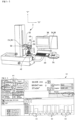
- FIG 1-1 shows a tool presetting device 2 or presetting device 2 for short - for measuring a tool 4 or complete tool 6 (tool holder 8 and tool 4) in detail.
- the presetting device 2 has an optical measuring device 10, in the form of a camera device 10, by means of which information can be recorded from the tool 4 or complete tool 6 - in short and simply put, it can be measured.
- the presetting device 2 has a computing and control unit 34, which includes a processor, a memory unit (memory for short), an interface with the camera device, an interface 36 with a machine tool and calculation and operating programs stored in the memory unit, executable by the computing and control unit 34, operable via a display means 38 and input means 40, such as the autonomous measurement of a tool 4 ("Maximum SE") , which is the focus here - and furthermore also the generation of data for a collision-relevant digital twin and a machining-relevant digital twin of a tool 4 or complete tool 6, as described in the DE 10 2022 123 017 A1 described.
- a computing and control unit 34 which includes a processor, a memory unit (memory for short), an interface with the camera device, an interface 36 with a machine tool and calculation and operating programs stored in the memory unit, executable by the computing and control unit 34, operable via a display means 38 and input means 40, such as the autonomous measurement of a tool 4 (“Maximum SE”) , which is the focus here
- the computing and control unit 34 is also provided - by means of corresponding calculation and operating programs - to run or carry out a conventional measurement of a tool 4 or a complete tool 6 - using the camera device 10 - whereby conventional presetting data are generated from the tool 4 or the complete tool 6.
- the computing and control unit 34 enables - also by means of corresponding calculation and operating programs and using the camera device 10 - to generate data of the tool 4 or the complete tool 6 for a collision check, namely the collision-relevant and the machining-relevant digital twin.
- the or all measurement or presetting data - including that from the autonomous measurement of a tool 4 ("Maximum SE") (collectively referred to as measurement or presetting data) - and/or data from the collision-relevant and the machining-relevant digital twin, in short the collision-relevant and the machining-relevant digital twin, can be provided - in the form of one or more data sets - in digital form for further machine processing, for example in the data formats VDA-FS, IFC, IGES, STEP, STL and DXF.
- the data or data sets can be transmitted/transmitted to the machine tool via the interface 36 with the machine tool (not shown) (where, among other things, the simulated collision check can be carried out or is carried out using the data).
- the presetting device 2 further comprises, as FIG 1-1 shows (see also FIGS. 2-1 to 4-1), the display means 38 in the form of a monitor 38 (with touchscreen functionality) and the input means 40, which is designed as a (separate) keyboard 40.
- the input means 40 is also designed as a touchscreen-functional monitor 38.
- An operator can operate the calculation and operating programs via the keyboard 40 and the touchscreen 38, whereby functionalities, data and status displays of the calculation and operating programs are displayed on the monitor 38 (and can also be operated via it), - and trigger a transfer of the data or data sets to the machine tool - via the interface 36.
- FIG 1-1 shows, the complete tool 6 is arranged on a spindle 42, which is rotatable about a rotational/central or longitudinal axis 46 (z-axis) - in particular automatically by an actuator not shown in detail - controlled by means of a corresponding functional program.
- a spindle 42 which is rotatable about a rotational/central or longitudinal axis 46 (z-axis) - in particular automatically by an actuator not shown in detail - controlled by means of a corresponding functional program.
- the aforementioned camera device 10 of the presetting device 2 is designed as a transmitted-light system.
- a camera 48 and an illumination means 50 are located on opposite sides of a complete tool 6 arranged on the spindle 42.
- the camera device 10 is mounted on a carriage 52. mounted - and can be moved along two axes ("x" and "z") manually, as well as automatically - controlled by a corresponding function program.
- Figures 2-1 to 4-1 illustrate the sequence of the functional program for the autonomous measurement of a tool or complete tool.
- FIG 2-1 shows the control menu or operating and display interface 32 as it is displayed on the display means 38/monitor/touchscreen 38 of the presetting device 2 - and via which the autonomous measurement of a tool or complete tool is carried out or started.
- Touching function button 44 "Maximum SE” starts the autonomous measurement of a tool or complete tool , which then runs completely operator-free or autonomously. This means that any tool, unknown at this point, can be measured (and created as a new tool in the tool management system (as a data record)) without any further operator assistance.
- the camera device 10 searcheses" for the (arbitrary and “unknown") tool 4 clamped/held in the spindle 42. This means that the camera device 10 moves autonomously along the central axis 46 of the tool (z-axis) until it detects/detects the "first parts/areas" of the tool 4. In doing so, it moves autonomously to the height of the highest point 12 of the tool 4 clamped/held in the spindle 42.
- a highest or uppermost point 12 of the tool 4 on the central axis (longitudinal axis) 46 of the tool (z-axis) can be determined.
- the previously "unknown” tool 4 is then determined/classified as a drilling tool. Further measurements of functional geometries 16 of a “drilling tool” (also referred to as “drill” for short) follow.
- the "unknown" tool 4 is a (ten-edged) milling tool (cf. FIG 3-1 ) no tip 14 will be found on tool 4 - and this tool 4 will therefore not be classified/recognized as a drilling tool.
- a radially outer edge 18 on the tool is then determined. This means that the camera device 10 moves radially outward (x-axis) to the radially outer edge 20 of the tool 4.
- the camera device 10 detects the radially outer edge 20 - and the spindle 42 begins to rotate the tool 4 or complete tool 6 clamped in it (about its longitudinal/central or z-axis 46).
- the camera device 10 continuously determines the contour 22 of the tool 4 in the respective rotational position.
- the determined contours 22 are evaluated, here using predefined comparison patterns, to determine whether a cutting edge 16 (functional geometry 16) of the tool 4 is recognizable in the contour profile (the respective rotational position of the tool 4). If a contour 22 is recognized as a cutting edge 16/functional geometry 16, it is also measured.
- the tool 4 is rotated completely at least once around its central or longitudinal or z-axis 46 (360°), whereby at the end of the rotation process - all cutting edges 16 (functional geometries 16) (if present in a cutting or milling tool) are recognized - and then, in such a case, also measured.
- tool 4 is (a) a milling or cutting tool - and (b) a how many cutter.
- FIG 2-1 in detail of it FIG 3-1 show the measurement of the (in this case ten) cutting edges 16 (functional geometries 16) of the - in this case - milling tool.
- the "x" dimensions, i.e., the radial dimension, of the ten cutting edges 16 are graphically displayed (in bar form (height of the bar corresponds to the radial dimension).
- the respective "z" dimensions (z-axis) of the ten cutting edges 16 are then also displayed accordingly.
- x and z dimensions could also be displayed simultaneously in superimposed form.
- the respective representations make it possible to quickly and easily recognize differences in the cutting edges 16 or their conditions, e.g. the outermost cutting edge 56 (cf. FIG 4-1 ) (FIGS 2-1 and 3-1 - cutting edge 1) vs. the innermost cutting edge 58 ( FIG 4-1 ) (FIGS 2-1 and 3-1 - cutting edge 3) (cf. FIG 2-1 or FIG 3-1 - marked accordingly by the two straight lines) or the highest cutting edge vs. the lowest cutting edge.
- FIG 4-1 shows a corresponding summary image 24 in which - using the measured cutting edges 16 - their cutting contours are shown superimposed together.
- FIG 4-1 shows the measured functional geometries/cutting edges 16 of the tool (in “x” and “z") superimposed, whereby - in the image (also mathematically determinable) - a maximum outer contour 26, referred to as the sum geometry 26 - here in “x” and “z” - is shown for the milling/tool 4.
- a minimum contour 28 can be derived - for example, also from the summation image 24 - or (also mathematically) determine which - expressed in simplified and clear terms (as a counterpart to the sum geometry 26) - forms a "minimal inner contour" 28.
- a concentricity, a flatness and a roundness of the tool 4 can then be determined.
- the cutting edges 16 (functional geometries 16) of the tool 4 have been measured, they are stored as a reference (in a memory or tool management system) - and are thus available as a comparison for newly measured cutting edges 16/functional geometries 16 of this tool 4 when this tool 4 is re-measured.
- wear information can be determined for tool 4. Other properties such as remaining tool life or tool life can then be derived from the wear information.
- a grinding wheel 4 can be assumed for such a tool 4 (including no tip 14 - see above), whose circumferential grinding wheel edge 18 (cf. functional geometry 16) is then measured.
- the cumulative image 24, cumulative geometry 26, and minimum contour 28 can be determined, saved, and evaluated (e.g., concentricity, flatness, etc.).
- the camera device 10 moves axially to the height at which the tool/drill 4 or its drill tip has its maximum outer diameter - and from there radially outwards - to the radially outer edge 20 of the tool.
- the camera device 10 detects the radially outer edge 20 - and the spindle 42 begins to rotate the tool/drill 4 clamped in it (around its longitudinal/central or z-axis 46).
- the camera device 10 continuously determines the contour 22 of the tool/drill 4 in the respective rotational position.
- the determined contours 22 are then evaluated to determine whether a cutting edge 16 (functional geometry 16) of the tool 4 is recognizable within the contour (the respective rotational position of the tool 4). If a contour 22 is recognized as a cutting edge 16/functional geometry 16, it is also measured.
- the tool/drill 4 is rotated completely around its central, longitudinal, or z-axis 46 (360°), whereby – at the end of the rotation process – all cutting edges 16 (functional geometries 16) are detected and then measured.
- the cumulative image 24, cumulative geometry 26, and minimum contour 28, as well as wear information, are determined, stored, and evaluated accordingly.
- the measurement of the tool is carried out in "only" one (first level - see FIGS. 2-1 and 3-1 "Level 1/1" - marked by a border), namely at the "outer cutting edge” 18 (near the tip 14 of the tool 4).
- Such a measurement, as described, can also be carried out at other axial heights (z-axis) (second/third plane etc.) on the tool 4, for example where the diameter of the tool 4 changes (e.g. steps in a "step drill") and/or where other or additional Functional geometries 16, for example (further) indexable/cutting inserts (functional geometries 16) are arranged on a tool, and/or at a (different) height.
- z-axis second/third plane etc.
- the camera device 10 then moves along the outer edge of the tool 4 until – in a further plane – further functional geometries 16 are detected, where the described measurement procedure (see above) is repeated.
- the cumulative image 24, cumulative geometry 26, and minimum contour 28, as well as wear information, can also be determined, stored, and evaluated accordingly.
- the start of the "digital twin” function program is carried out in accordance with the "Maximum SE” function program described above, whereby the generation of the (collision-relevant) digital twin is started (not shown) autonomously or by touching the "Digital Twin” function button on the display device 38/monitor 38.
- the scanning is carried out - in this case with a non-rotating tool 4 - by a 2D scan of the complete tool 6 carried out by the camera device 10, whereby a bilateral contour of the complete tool 6 is measured in a predetermined fixed position of the complete tool 6 (fixed spindle 42).
- the camera device 10 automatically moves to different heights of the complete tool 6 and takes a picture of the complete tool 6 or a section of the complete tool 6 at each of these heights, from which pictures the contour or the contour profile of the complete tool 6 is then "extracted", which then forms the (two-dimensional) digital image.
- the camera device 10 is moved step by step, first from below, i.e. from the lower end of the complete tool 6, upwards, i.e. to the upper end of the complete tool 6, whereby the camera device 10 is aligned here with the contour of one side of the complete tool 6 - and in this way the contour of one side of the complete tool 6 can be determined.
- the camera device 10 then moves step by step from top to bottom, whereby the camera device 10 is aligned with the contour of the other side of the complete tool 6 - and the contour of the other side of the complete tool 6 can be determined.
- a first cutting point, a cutting start point, and a second cutting point, a cutting end point are then measured on the tool 4 and the complete tool 6 by means of the camera device 10.
- an operator can move the camera device 10 to the two corresponding heights, which he can control via a display on the monitor 38, focus on the cutting start point or cutting end point there, and then trigger the respective measurement using the keyboard 40. Otherwise, this is done autonomously.
- a cutting edge area is then determined in the digital image using the measured first and second cutting edge points or using the nearest points determined in the digital image ("collision-relevant digital twin").
- the scanning is carried out - in this case with rotating tool 4 - by a 3D scan of the complete tool 6 carried out by the camera device 10, whereby a one-sided contour of the complete tool is measured - with the complete tool 6 rotated differently (rotating spindle 42).
- the camera device 10 automatically moves to different heights of the complete tool 6 and, at these heights, takes pictures of the complete tool 6 or of a section of the complete tool 6 in different (by means of the spindle 42) rotated complete tool positions, from which pictures the envelope contour of the complete tool 6 is then "extracted", which then forms the three-dimensional digital image.
- the camera device 10 is moved step by step, preferably from below, ie from the lower end of the complete tool 6, upwards, ie to the upper end of the complete tool 6, wherein the camera device 10 is focused here on the contour of one side of the complete tool 6 At the approached heights, different shots of the complete tool 6 are taken - each in differently rotated complete tool positions.
- a first cutting point, a cutting start point, and a second cutting point, a cutting end point, on the tool 6 or the complete tool 6 are then detected and measured by means of the camera device 10, if necessary using artificial intelligence.
- an operator can move the camera device 10 to the two corresponding heights, which he can control via a display on the monitor 38, focus on the cutting start point or cutting end point there, and then trigger the respective measurement using the keyboard 40. Otherwise, this is done autonomously.
- a cutting edge area is then determined in the digital image using the measured first and second cutting edge points or using these determined nearest points in the digital image ("collision-relevant digital twin") and marked as such.
- the machine tool and/or an external programming station then carries out the collision simulation.
- FIG 5-1 shows - as part of the carriage 52 of the presetting device 2 - an (approximately U-shaped) measuring device carrier 64 in the presetting device 2 with a reading device/device 62 integrated therein for reading a data carrier 60 on the tool holder 8.
- the complete tool 6—more precisely, the tool holder 8—held or clamped in the spindle 42 provides a data carrier 60, embodied here, for example, as a contactless readable data carrier, such as an RFID chip, by means of which the tool holder 8 can be fully automatically identified (also within the framework of prescribed autonomous processes) and further measurement data can be recorded for it.
- the position of the data carrier 60 on the tool holder 8 is standardized in this case (HSK/SK tool holder).
- All tool-relevant data is stored - contactlessly here - on the data carrier 60, which is connected to the tool holder 8 (for example, as shown in the DE 10 2016 102 692 A1 described).
- a code/value or similar that uniquely identifies the tool can also be stored on the chip.
- FIG 5-1 shows, the complete tool 6 or the tool holder 8 is arranged on the spindle 42, which - in particular by an actuator not shown in detail - can be automatically rotated about the rotational/central or longitudinal axis 46 (z-axis).
- the mentioned camera device 10 of the presetting device 2 (cf. FIG 1-1 Camera 48 and illumination means 50) is arranged on the U-shaped measuring device carrier 64, which is part of the carriage 52 of the presetting device 2, - and which, as in FIG 5-1 indicated, along two axes ("x" and "z” 46) can be moved manually, as well as automatically (cf. autonomous process - see above).
- a reading device 62 - with a read/write head 66 that can be moved (in the horizontal plane) - is integrated, which can read data from the data carrier 60 on the tool holder 8.
- the read/write head 66 of the reading device 62 moves out of the measuring device carrier 64 directly towards the data carrier (in this position the data can be read from the data carrier 60) - and also back into the measuring device carrier.
- the reading of data from the data carrier 60 takes place either autonomously integrated into the process or as a separate autonomous process by means of a function button 44 on the touchscreen 38 (touching the function button 44 then starts the autonomous reading process).
- the measuring device carrier 64 moves autonomously along the center/z-axis 46 into a home position whose axial height corresponds to the axial height at which the data carrier 60 is attached to the tool holder 8.
- the complete tool 6 or the tool holder 8 is rotated autonomously around the z-axis by means of the spindle 42 until the data chip 60, which is arranged in a standardized position on the tool holder 8, comes to rest in front of the reader 62.
- the angle value of the chip position - which is adapter-dependent - is known in the system, but can be searched for with the aid of a camera if necessary.
- a read/write head 66 of the reader 62 moves directly to the data carrier 60 - and reads its data The read/write head 66 then moves back.
- the camera unit 10 searches for the data carrier 60 on the tool holder 8 and thus detects or determines its position.
- the height positioning of the measuring device carrier 64 and spindle rotation, as well as the subsequent reading, can then be carried out accordingly.
- Such a reading device 62 in the measuring device carrier 64 of a presetting device 2 can also be used in a corresponding (also functional) manner in any other machine tool.
- the read/write head 66 could also simply be a special camera mounted on the measuring device carrier 64 that identifies the tool holder 8 - or a reader 62 that reads a marking, such as a QR code, on the tool holder 8. Such a marking can then identify the tool holder 8 or contain encoded tool data.
Landscapes
- Engineering & Computer Science (AREA)
- Mechanical Engineering (AREA)
- Manufacturing & Machinery (AREA)
- Physics & Mathematics (AREA)
- Human Computer Interaction (AREA)
- General Physics & Mathematics (AREA)
- Automation & Control Theory (AREA)
- Geometry (AREA)
- General Factory Administration (AREA)
- Automatic Tool Replacement In Machine Tools (AREA)
- Machine Tool Sensing Apparatuses (AREA)
- Numerical Control (AREA)
Applications Claiming Priority (3)
| Application Number | Priority Date | Filing Date | Title |
|---|---|---|---|
| DE102023124591 | 2023-09-12 | ||
| DE102023126747.7A DE102023126747A1 (de) | 2023-09-12 | 2023-09-29 | Bearbeitungsmanagement bei einer Bearbeitung eines Gesamtwerkzeugs aus einem Werkzeughalter und einem Werkzeug |
| DE102024122026.0A DE102024122026A1 (de) | 2024-08-01 | 2024-08-01 | Verfahren und Vorrichtung zum autonomen Vermessen eines Werkzeugs oder eines Komplettwerkzeugs |
Publications (1)
| Publication Number | Publication Date |
|---|---|
| EP4530771A1 true EP4530771A1 (fr) | 2025-04-02 |
Family
ID=92710936
Family Applications (1)
| Application Number | Title | Priority Date | Filing Date |
|---|---|---|---|
| EP24198985.4A Pending EP4530771A1 (fr) | 2023-09-12 | 2024-09-06 | Gestion d'usinage lors de l'usinage d'un outil global à partir d'un porte-outil et d'un outil |
Country Status (4)
| Country | Link |
|---|---|
| US (1) | US20250083276A1 (fr) |
| EP (1) | EP4530771A1 (fr) |
| JP (1) | JP2025040975A (fr) |
| CN (1) | CN119609688A (fr) |
Citations (7)
| Publication number | Priority date | Publication date | Assignee | Title |
|---|---|---|---|---|
| DE102006024904A1 (de) * | 2006-05-24 | 2007-11-29 | Franz Klaiber | Verfahren zum Bereitstellen von Werkzeugen für das Herstellen und/oder Bearbeiten von Gegenständen |
| DE102016102692A1 (de) | 2016-02-16 | 2017-08-17 | Franz Haimer Maschinenbau Kg | Vorrichtung zur Befestigung eines Datenträgers an einer Werkzeugaufnahme, Werkzeugaufnahme und Werkzeuganordnung |
| DE102017117059A1 (de) * | 2017-07-26 | 2019-01-31 | Franz Haimer Maschinenbau Kg | Werkzeugmaschinensystem mit automatischer wuchtprotokollverwertung |
| DE102017117840A1 (de) | 2017-08-07 | 2019-02-07 | Franz Haimer Maschinenbau Kg | Erstellung eines digitalen zwillings in einem bearbeitungszentrum |
| EP3747596A2 (fr) * | 2019-06-07 | 2020-12-09 | E. Zoller GmbH & Co. KG | Station de multitension et de mesure et/ou de réglage pour outils et procédé de montage/démontage d'un outil dans/d'un porte-outil |
| DE102022123017A1 (de) | 2022-09-09 | 2024-03-14 | Franz Haimer Maschinenbau Kg | Vorrichtung zum Vermessen eines Werkzeugs oder eines Komplettwerkzeugs und Verfahren zum Erstellen eines digitalen Abbilds eines Werkzeugs oder Komplettwerkzeugs |
| DE102024122026A1 (de) | 2024-08-01 | 2026-02-05 | Franz Haimer Maschinenbau Kg | Verfahren und Vorrichtung zum autonomen Vermessen eines Werkzeugs oder eines Komplettwerkzeugs |
-
2024
- 2024-09-06 EP EP24198985.4A patent/EP4530771A1/fr active Pending
- 2024-09-12 CN CN202411279837.4A patent/CN119609688A/zh active Pending
- 2024-09-12 JP JP2024157973A patent/JP2025040975A/ja active Pending
- 2024-09-12 US US18/883,044 patent/US20250083276A1/en active Pending
Patent Citations (7)
| Publication number | Priority date | Publication date | Assignee | Title |
|---|---|---|---|---|
| DE102006024904A1 (de) * | 2006-05-24 | 2007-11-29 | Franz Klaiber | Verfahren zum Bereitstellen von Werkzeugen für das Herstellen und/oder Bearbeiten von Gegenständen |
| DE102016102692A1 (de) | 2016-02-16 | 2017-08-17 | Franz Haimer Maschinenbau Kg | Vorrichtung zur Befestigung eines Datenträgers an einer Werkzeugaufnahme, Werkzeugaufnahme und Werkzeuganordnung |
| DE102017117059A1 (de) * | 2017-07-26 | 2019-01-31 | Franz Haimer Maschinenbau Kg | Werkzeugmaschinensystem mit automatischer wuchtprotokollverwertung |
| DE102017117840A1 (de) | 2017-08-07 | 2019-02-07 | Franz Haimer Maschinenbau Kg | Erstellung eines digitalen zwillings in einem bearbeitungszentrum |
| EP3747596A2 (fr) * | 2019-06-07 | 2020-12-09 | E. Zoller GmbH & Co. KG | Station de multitension et de mesure et/ou de réglage pour outils et procédé de montage/démontage d'un outil dans/d'un porte-outil |
| DE102022123017A1 (de) | 2022-09-09 | 2024-03-14 | Franz Haimer Maschinenbau Kg | Vorrichtung zum Vermessen eines Werkzeugs oder eines Komplettwerkzeugs und Verfahren zum Erstellen eines digitalen Abbilds eines Werkzeugs oder Komplettwerkzeugs |
| DE102024122026A1 (de) | 2024-08-01 | 2026-02-05 | Franz Haimer Maschinenbau Kg | Verfahren und Vorrichtung zum autonomen Vermessen eines Werkzeugs oder eines Komplettwerkzeugs |
Also Published As
| Publication number | Publication date |
|---|---|
| US20250083276A1 (en) | 2025-03-13 |
| CN119609688A (zh) | 2025-03-14 |
| JP2025040975A (ja) | 2025-03-25 |
Similar Documents
| Publication | Publication Date | Title |
|---|---|---|
| DE102008035710B4 (de) | Verfahren zum selbsttätigen Zurückführen eines Werkzeugs einer programmgesteuerten Werkzeugmaschine | |
| US4998206A (en) | Automated method and apparatus for fabricating sheet metal parts and the like using multiple manufacturing stations | |
| EP2540432B1 (fr) | Machine de traitement au laser dotée de composants échangeables | |
| DE112007001755T5 (de) | Verfahren und Vorrichtung zur Kombinationsbearbeitung | |
| DE2940444C2 (de) | Kopiersteuerungsvorrichtung für eine Kopierfräsmaschine mit Werkzeugwechseleinrichtung | |
| DE102019006466A1 (de) | Werkzeugschneiden-Verstellkopf, Verfahren zu dessen Betrieb und zur Korrektur des Werkzeugschneiden-Verschleißes | |
| EP3732540A1 (fr) | Procédé d'usinage de pièces et système d'usinage | |
| CN110032159A (zh) | 船用柴油机关重件切削加工控制系统实现方法 | |
| EP4336142A1 (fr) | Dispositif de mesure d'un outil ou d'un outil complet et procédé de création d'une représentation numérique d'un outil ou d'un outil complet | |
| EP2664973B1 (fr) | Procédé de gestion des données outil | |
| DE102010054744A1 (de) | Schneidwerkzeug zu gewerblichen Zwecken in Kombination mit einer EDV-Anlage | |
| DE102019126937A1 (de) | Werkzeugmaschine | |
| EP4707971A1 (fr) | Procédé et dispositif de mesure autonome d'un outil ou d'un outil complet | |
| EP1892596A2 (fr) | Système et procédé destinés à l'organisation de pièces à usiner à traiter | |
| EP3933526B1 (fr) | Procédé de surveillance et de commande d'une machine-outil et machine-outil | |
| CN110049110B (zh) | 一种云智能系统 | |
| EP4530771A1 (fr) | Gestion d'usinage lors de l'usinage d'un outil global à partir d'un porte-outil et d'un outil | |
| EP4596173A1 (fr) | Procédé avec un appareil de réglage et/ou de mesure d'outil, appareil de réglage d'outil et/ou de mesure d'outil, appareil de serrage d'outil et produit programme informatique | |
| EP3951524A1 (fr) | Procédé de fonctionnement d'un système et système couplé doté d'un nombre de stations de production destinés à la fabrication d'un produit | |
| DE102023126747A1 (de) | Bearbeitungsmanagement bei einer Bearbeitung eines Gesamtwerkzeugs aus einem Werkzeughalter und einem Werkzeug | |
| DE202019106365U1 (de) | Arbeitsverteilungssystem zur Formenherstellung | |
| KR20200065937A (ko) | 금형제작용 공구 공작의 검증 및 관리 시스템 | |
| CN116117596B (en) | Method and system for accurately controlling cutting parameters and service life of cutter | |
| EP4497046B1 (fr) | Procédé de vérification d'un processus d'usinage pour des collisions au moyen d'une pièce de remplacement | |
| AT526167B1 (de) | Computerimplementiertes Verfahren zum Bearbeiten eines Werkstückes an einer Werkzeugmaschine, sowie eine Werkzeugmaschine, ein Computerprogrammprodukt und ein computerlesbares Medium |
Legal Events
| Date | Code | Title | Description |
|---|---|---|---|
| PUAI | Public reference made under article 153(3) epc to a published international application that has entered the european phase |
Free format text: ORIGINAL CODE: 0009012 |
|
| STAA | Information on the status of an ep patent application or granted ep patent |
Free format text: STATUS: THE APPLICATION HAS BEEN PUBLISHED |
|
| AK | Designated contracting states |
Kind code of ref document: A1 Designated state(s): AL AT BE BG CH CY CZ DE DK EE ES FI FR GB GR HR HU IE IS IT LI LT LU LV MC ME MK MT NL NO PL PT RO RS SE SI SK SM TR |
|
| STAA | Information on the status of an ep patent application or granted ep patent |
Free format text: STATUS: REQUEST FOR EXAMINATION WAS MADE |
|
| 17P | Request for examination filed |
Effective date: 20251001 |