EP4530662A1 - Method for tracking objects and radar device - Google Patents
Method for tracking objects and radar device Download PDFInfo
- Publication number
- EP4530662A1 EP4530662A1 EP23199955.8A EP23199955A EP4530662A1 EP 4530662 A1 EP4530662 A1 EP 4530662A1 EP 23199955 A EP23199955 A EP 23199955A EP 4530662 A1 EP4530662 A1 EP 4530662A1
- Authority
- EP
- European Patent Office
- Prior art keywords
- threshold
- innovation vector
- tracked object
- marked
- measurement data
- Prior art date
- Legal status (The legal status is an assumption and is not a legal conclusion. Google has not performed a legal analysis and makes no representation as to the accuracy of the status listed.)
- Pending
Links
Images
Classifications
-
- G—PHYSICS
- G01—MEASURING; TESTING
- G01S—RADIO DIRECTION-FINDING; RADIO NAVIGATION; DETERMINING DISTANCE OR VELOCITY BY USE OF RADIO WAVES; LOCATING OR PRESENCE-DETECTING BY USE OF THE REFLECTION OR RERADIATION OF RADIO WAVES; ANALOGOUS ARRANGEMENTS USING OTHER WAVES
- G01S13/00—Systems using the reflection or reradiation of radio waves, e.g. radar systems; Analogous systems using reflection or reradiation of waves whose nature or wavelength is irrelevant or unspecified
- G01S13/88—Radar or analogous systems specially adapted for specific applications
- G01S13/93—Radar or analogous systems specially adapted for specific applications for anti-collision purposes
- G01S13/931—Radar or analogous systems specially adapted for specific applications for anti-collision purposes of land vehicles
-
- G—PHYSICS
- G01—MEASURING; TESTING
- G01S—RADIO DIRECTION-FINDING; RADIO NAVIGATION; DETERMINING DISTANCE OR VELOCITY BY USE OF RADIO WAVES; LOCATING OR PRESENCE-DETECTING BY USE OF THE REFLECTION OR RERADIATION OF RADIO WAVES; ANALOGOUS ARRANGEMENTS USING OTHER WAVES
- G01S13/00—Systems using the reflection or reradiation of radio waves, e.g. radar systems; Analogous systems using reflection or reradiation of waves whose nature or wavelength is irrelevant or unspecified
- G01S13/02—Systems using reflection of radio waves, e.g. primary radar systems; Analogous systems
- G01S13/06—Systems determining position data of a target
-
- G—PHYSICS
- G01—MEASURING; TESTING
- G01S—RADIO DIRECTION-FINDING; RADIO NAVIGATION; DETERMINING DISTANCE OR VELOCITY BY USE OF RADIO WAVES; LOCATING OR PRESENCE-DETECTING BY USE OF THE REFLECTION OR RERADIATION OF RADIO WAVES; ANALOGOUS ARRANGEMENTS USING OTHER WAVES
- G01S13/00—Systems using the reflection or reradiation of radio waves, e.g. radar systems; Analogous systems using reflection or reradiation of waves whose nature or wavelength is irrelevant or unspecified
- G01S13/66—Radar-tracking systems; Analogous systems
- G01S13/72—Radar-tracking systems; Analogous systems for two-dimensional [2D] tracking, e.g. combination of angle and range tracking, track-while-scan radar
- G01S13/723—Radar-tracking systems; Analogous systems for two-dimensional [2D] tracking, e.g. combination of angle and range tracking, track-while-scan radar by using numerical data
-
- G—PHYSICS
- G01—MEASURING; TESTING
- G01S—RADIO DIRECTION-FINDING; RADIO NAVIGATION; DETERMINING DISTANCE OR VELOCITY BY USE OF RADIO WAVES; LOCATING OR PRESENCE-DETECTING BY USE OF THE REFLECTION OR RERADIATION OF RADIO WAVES; ANALOGOUS ARRANGEMENTS USING OTHER WAVES
- G01S13/00—Systems using the reflection or reradiation of radio waves, e.g. radar systems; Analogous systems using reflection or reradiation of waves whose nature or wavelength is irrelevant or unspecified
- G01S13/66—Radar-tracking systems; Analogous systems
- G01S13/72—Radar-tracking systems; Analogous systems for two-dimensional [2D] tracking, e.g. combination of angle and range tracking, track-while-scan radar
- G01S13/723—Radar-tracking systems; Analogous systems for two-dimensional [2D] tracking, e.g. combination of angle and range tracking, track-while-scan radar by using numerical data
- G01S13/726—Multiple target tracking
-
- G—PHYSICS
- G01—MEASURING; TESTING
- G01S—RADIO DIRECTION-FINDING; RADIO NAVIGATION; DETERMINING DISTANCE OR VELOCITY BY USE OF RADIO WAVES; LOCATING OR PRESENCE-DETECTING BY USE OF THE REFLECTION OR RERADIATION OF RADIO WAVES; ANALOGOUS ARRANGEMENTS USING OTHER WAVES
- G01S7/00—Details of systems according to groups G01S13/00, G01S15/00, G01S17/00
- G01S7/02—Details of systems according to groups G01S13/00, G01S15/00, G01S17/00 of systems according to group G01S13/00
- G01S7/40—Means for monitoring or calibrating
- G01S7/4052—Means for monitoring or calibrating by simulation of echoes
-
- G—PHYSICS
- G06—COMPUTING OR CALCULATING; COUNTING
- G06T—IMAGE DATA PROCESSING OR GENERATION, IN GENERAL
- G06T7/00—Image analysis
- G06T7/20—Analysis of motion
- G06T7/277—Analysis of motion involving stochastic approaches, e.g. using Kalman filters
Definitions
- the present invention relates to methods for tracking objects and to a radar device. More particularly, the invention relates to the tracking of objects based on radar data.
- ADAS Advanced driver-assistance systems
- Perception is the subsystem in an ADAS responsible for processing and condensing sensor data into a low-dimensional representation of the environment around the host vehicle (HV).
- HV host vehicle
- the two main tasks that the subsystem performs are classification and tracking.
- Kalman-filter As provided in Kalman, "A new approach to linear filtering and prediction problems", Journal of Basic Engineering, 82 (1): 35-45, (1960 ) and Kalman et al., “New results in linear filtering and prediction theory", Journal of Basic Engineering, 83: 95-108 (1961 ).
- the Kalman-filter method comprises two key steps, namely prediction and update.
- a motion model is used for propagating the state and uncertainties forward in time.
- the state is updated and uncertainties are determined with a sensor measurement.
- the state estimate is refined by a correction term that is dependent on the predicted state, the measurement and an appropriately chosen weighting factor.
- AEB automatic emergency braking
- the invention provides methods for tracking objects and a radar device.
- the invention provides a computer-implemented method for tracking objects, comprising tracking at least one object with a Kalman-filter method, using radar measurement data, wherein the Kalman-filter method comprises computing an innovation vector based on the radar measurement data.
- the method further comprises storing, for each tracked object, a component of the innovation vector corresponding to the tracked object.
- the method further comprises comparing, for each tracked object, an updated value of the innovation vector with a predefined first threshold. If the updated value of the innovation vector is above the first threshold, the tracked object is marked as unreliable and the first threshold is stored as a new value of the component of the innovation vector.
- the method further comprises comparing, for each tracked object, an updated value of the innovation vector with a predefined second threshold. The second threshold is smaller than the first threshold. If the updated value of the innovation vector is below the second threshold, a tracked object which has been marked as unreliable is marked as reliable and the second threshold is stored as a new value of the component of the innovation vector.
- the invention provides a method for tracking objects, comprising generating radar measurement data by a radar device.
- a computing device tracks at least one object with a Kalman-filter method, using the radar measurement data, wherein the Kalman-filter method comprises computing an innovation vector based on the radar measurement data.
- the computing device stores, for each tracked object, a component of the innovation vector corresponding to the tracked object.
- the computing device compares, for each tracked object, an updated value of the innovation vector with a predefined first threshold. If the updated value of the innovation vector is above the first threshold, the tracked object is marked as unreliable and the first threshold is stored as a new value of the component of the innovation vector.
- the computing device compares, for each tracked object, an updated value of the innovation vector with a predefined second threshold. The second threshold is smaller than the first threshold. If the updated value of the innovation vector is below the second threshold, a tracked object which has been marked as unreliable is marked as reliable and the second threshold is stored as a new value of the component of the innovation vector.
- the invention provides a radar device, comprising at least one radar antenna configured to generate radar measurement data.
- the radar device further comprises a computing device, configured to track at least one object with a Kalman-filter method, using the radar measurement data, wherein the Kalman-filter method comprises computing an innovation vector based on the radar measurement data.
- the computing device stores, for each tracked object, a component of the innovation vector corresponding to the tracked object.
- the computing device compares, for each tracked object, an updated value of the innovation vector with a predefined first threshold. If the updated value of the innovation vector is above the first threshold, the tracked object is marked as unreliable and the first threshold is stored as a new value of the component of the innovation vector.
- the computing device compares, for each tracked object, an updated value of the innovation vector with a predefined second threshold.
- the second threshold is smaller than the first threshold. If the updated value of the innovation vector is below the second threshold, a tracked object which has been marked as unreliable is marked as reliable and the second threshold is stored as a new value of the component of the innovation vector.
- tracked objects can be marked as reliable or unreliable, i.e., a state is assigned to the tracked objects.
- a state is assigned to the tracked objects.
- the Kalman-filter method comprises a determination of a weighting factor, the so-called Kalman gain, from the process and measurement noise, as a minimum mean-square error estimator.
- the Kalman gain itself is not used for association errors.
- the innovation vector is also computed in Kalman-filter method and can be utilized for finding possibly erroneous updates.
- the innovation vector can be considered as a representation of the similarity between the measurement and its estimate based on the object's predicted state and a pre-defined measurement model. The higher the values of the innovation vector, the greater the difference between the states.
- a tracked object is flagged as unreliable immediately if a given component of the innovation vector indicates that the association is likely erroneous.
- one keeps track of the relevant components of the innovation vector without introducing a significant memory overhead. This way, by marking tracked objects, one can propagate the information about this behavior to higher-level subsystems of the signal chain.
- memory corresponding to the tracked object is reset. This allows to define a clean state. A member where the component of the innovation vector has been stored can be reset to indicate reliable behavior.
- the tracked object is treated as unreliable until a new measurement confirms that there is indeed a real-world object with a state similar to that of the tracked object. This indicates that previous updates were necessary, even though the measured states and the object states were perceptibly different. Once it is established, the history of faulty behavior is instantly forgotten, and the tracked object is treated as normal (reliable) again.
- the innovation vector corresponds to a difference between radar measurement data and a model-based prediction.
- the radar measurement data comprises location data. That is, the innovation vector may comprise location entries.
- At least one function of a vehicle is controlled, using information of the tracked objects.
- an AEB function can be controlled based on the behavior of the tracked objects.
- the at least one function of the vehicle is controlled, taking into account whether the tracked object is marked as reliable or unreliable.
- process steps are for clarity and is generally not intended to imply any particular chronological order. In particular, several process steps can also be carried out simultaneously.
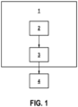
- Figure 1 shows a block diagram of a radar device 1 which comprises at least one radar antenna 2 for generating radar measurement data.
- the at least one radar antenna 2 emits radar signals and receives the reflected radar signals. Based on the reflections, locations of possible objects can be tracked.
- the radar measurement data may comprise location data.
- the radar device 1 further comprises a computing device 3, which may comprise at least one processor, microprocessor, integrated current, and the like.
- the computing device 3 may further comprise at least one memory for storing radar measurement data and instructions.
- the computing device 3 is configured to track at least one object with a Kalman-filter method, using the radar measurement data.
- the Kalman-filter method comprises a prediction step and an update step.
- a motion model is used for propagating the state and uncertainties forward in time.
- the update step the state is updated and uncertainties are determined with a sensor measurement (i.e., using the radar measurement data).
- the Kalman-filter method comprises the computation of an innovation vector based on the radar measurement data.
- the innovation vector corresponds to a difference between radar measurement data and a model-based prediction.
- the computing device 3 stores, for each tracked object, a component of the innovation vector corresponding to the tracked object.
- the computing device 3 may store the given component in a member.
- First and second predefined thresholds are defined.
- the computing device 3 compares, for each tracked object, an updated value of the innovation vector with the predefined first threshold and the second predefined threshold.
- the second threshold is smaller than the first threshold.
- the tracked object is marked as unreliable and the first threshold is stored as a new value of the component of the innovation vector.
- the first threshold is stored as a new value of the component of the innovation vector, this value may be kept until the updated value of the innovation vector is below the second threshold.
- the computing device 3 If no radar measurement data is contributing to a tracked object which has been marked as unreliable for a predefined period of time, the computing device 3 resets memory corresponding to the tracked object.
- the information on the tracked objects can be provided to an external ADAS device 4.
- the ADAS device 4 may control a function of a vehicle, wherein the vehicle comprises the radar device 1, using information of the tracked objects.
- the at least one function of the vehicle can be controlled by taking into account whether the tracked object is marked as reliable or unreliable.
- the at least one function can comprise an AEB function.
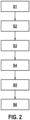
- Figure 2 shows a flow chart of a method for tracking objects.
- step S 1 radar measurement data is generated by a radar device, in particular the radar device 1 described above.
- the radar measurement data may comprise location data.
- a computing device (in particular, the computing device 3 described above) tracks at least one object with a Kalman-filter method, using the radar measurement data.
- the Kalman-filter method comprises computing an innovation vector based on the radar measurement data.
- the innovation vector corresponds to a difference between radar measurement data and a model-based prediction.
- step S3 the computing device 3 stores, for each tracked object, a component of the innovation vector corresponding to the tracked object.
- step S4 the computing device 3 compares, for each tracked object, an updated value of the innovation vector with a predefined first threshold. If the updated value of the innovation vector is above the first threshold, the tracked object is marked as unreliable and the first threshold is stored as a new value of the component of the innovation vector.
- the first threshold denotes the upper limit of allowed values of a given component. If an update arrives with a higher innovation component, the object will be marked as unreliable.
- step S5 the computing device 3 compares, for each tracked object, an updated value of the innovation vector with a predefined second threshold.
- the second threshold is smaller than the first threshold. If the updated value of the innovation vector is below the second threshold, a tracked object which has been marked as unreliable is re-labelled as reliable and the second threshold is stored as a new value of the component of the innovation vector.
- the second threshold denotes a remarkably good agreement between a measurement and current object states.
- the computing device 3 can overwrite parameters at each update with radar locations.
- the first threshold is stored as a new value of the component of the innovation vector, this value may be kept until the updated value of the innovation vector is below the second threshold.
- step S6 at least one function of the vehicle which comprises the radar device 1 is controlled, using information of the tracked objects.
- the at least one function of the vehicle is controlled, taking into account whether the tracked object is marked as reliable or unreliable.
- Steps S2 to S5 of the method above can be considered to correspond to a computer-implemented method for tracking objects.
Landscapes
- Engineering & Computer Science (AREA)
- Radar, Positioning & Navigation (AREA)
- Remote Sensing (AREA)
- Physics & Mathematics (AREA)
- Computer Networks & Wireless Communication (AREA)
- General Physics & Mathematics (AREA)
- Electromagnetism (AREA)
- Radar Systems Or Details Thereof (AREA)
Priority Applications (1)
| Application Number | Priority Date | Filing Date | Title |
|---|---|---|---|
| EP23199955.8A EP4530662A1 (de) | 2023-09-27 | 2023-09-27 | Method for tracking objects and radar device |
Applications Claiming Priority (1)
| Application Number | Priority Date | Filing Date | Title |
|---|---|---|---|
| EP23199955.8A EP4530662A1 (de) | 2023-09-27 | 2023-09-27 | Method for tracking objects and radar device |
Publications (1)
| Publication Number | Publication Date |
|---|---|
| EP4530662A1 true EP4530662A1 (de) | 2025-04-02 |
Family
ID=88204187
Family Applications (1)
| Application Number | Title | Priority Date | Filing Date |
|---|---|---|---|
| EP23199955.8A Pending EP4530662A1 (de) | 2023-09-27 | 2023-09-27 | Method for tracking objects and radar device |
Country Status (1)
| Country | Link |
|---|---|
| EP (1) | EP4530662A1 (de) |
Citations (1)
| Publication number | Priority date | Publication date | Assignee | Title |
|---|---|---|---|---|
| WO2021247427A1 (en) * | 2020-05-31 | 2021-12-09 | Qualcomm Incorporated | Clustering in automotive imaging |
-
2023
- 2023-09-27 EP EP23199955.8A patent/EP4530662A1/de active Pending
Patent Citations (1)
| Publication number | Priority date | Publication date | Assignee | Title |
|---|---|---|---|---|
| WO2021247427A1 (en) * | 2020-05-31 | 2021-12-09 | Qualcomm Incorporated | Clustering in automotive imaging |
Non-Patent Citations (4)
| Title |
|---|
| KALMAN ET AL.: "New results in linear filtering and prediction theory", JOURNAL OF BASIC ENGINEERING, vol. 83, 1961, pages 95 - 108 |
| KALMAN: "A new approach to linear filtering and prediction problems", JOURNAL OF BASIC ENGINEERING, vol. 82, no. 1, 1960, pages 35 - 45, XP008039411 |
| MUS&CARON ET AL: "Correlated Doppler-assisted target tracking in clutter", IET RADAR SONAR NAVIGATION, THE INSTITUTION OF ENGINEERING AND TECHNOLOGY, UK, vol. 7, no. 1, 3 January 2013 (2013-01-03), pages 94 - 100, XP006043692, ISSN: 1751-8784, DOI: 10.1049/IET-RSN.2012.0115 * |
| WIKIPEDIA: KALMAN FILTER: "Wikipedia: Kalman filter", 24 September 2023 (2023-09-24), XP093132545, Retrieved from the Internet <URL:https://en.wikipedia.org/w/index.php?title=Kalman_filter&oldid=1176917005> [retrieved on 20240219] * |
Similar Documents
| Publication | Publication Date | Title |
|---|---|---|
| JP6818907B2 (ja) | 障害物認識装置および障害物認識方法 | |
| US12030507B2 (en) | Method and system for predicting a trajectory of a target vehicle in an environment of a vehicle | |
| US20080128546A1 (en) | Tracking of a moving object | |
| CN111267860B (zh) | 用于车辆的传感器融合目标预测装置和方法、以及车辆 | |
| KR102203960B1 (ko) | 위성항법보강시스템을 위한 기계학습기반 gnss 무결성 감시 방법 | |
| US11567501B2 (en) | Method and system for fusing occupancy maps | |
| US6907347B2 (en) | Systems and method for estimating speed and pitch sensor errors | |
| JP2018018204A (ja) | 能力評価システム | |
| GB2574257A (en) | Vehicle dynamics estimation method and apparatus | |
| EP4056441A1 (de) | Back propagations-basierte adas/ad-bewegungsplanung und -steuerung | |
| JP4884096B2 (ja) | 物体識別システム | |
| EP4530662A1 (de) | Method for tracking objects and radar device | |
| US20230054590A1 (en) | Validation of surrounding objects percieved by an ads-equipped vehicle | |
| US11613272B2 (en) | Lane uncertainty modeling and tracking in a vehicle | |
| JP4900611B2 (ja) | オプトエレクトロニクス利用の監視システムにおける点状の目標の検出及びトラッキング方法 | |
| JP4151631B2 (ja) | 物体検出装置 | |
| JP2021051459A (ja) | 衝突確率算出装置、及び衝突確率算出方法 | |
| CN116324502A (zh) | 用于跟踪对象的方法、计算机程序、存储介质、设备 | |
| CN115342819B (zh) | 无模型车道跟踪系统 | |
| US20250209321A1 (en) | System identification apparatus, system identification method and non-transitory storage medium | |
| JP7666746B2 (ja) | 物体追跡装置 | |
| JP2025169214A (ja) | 機械学習モデルを使用してデータ集合のデータ要素を分類するためのコンピュータ実装された方法 | |
| CN119881982B (zh) | 建筑爬架的状态监测方法、设备、介质及程序产品 | |
| US20250304080A1 (en) | Evaluation of convergence time and adjustment based on evaluation of convergence time | |
| US20230071221A1 (en) | Method for improving the estimation of existence probabilities |
Legal Events
| Date | Code | Title | Description |
|---|---|---|---|
| PUAI | Public reference made under article 153(3) epc to a published international application that has entered the european phase |
Free format text: ORIGINAL CODE: 0009012 |
|
| STAA | Information on the status of an ep patent application or granted ep patent |
Free format text: STATUS: THE APPLICATION HAS BEEN PUBLISHED |
|
| AK | Designated contracting states |
Kind code of ref document: A1 Designated state(s): AL AT BE BG CH CY CZ DE DK EE ES FI FR GB GR HR HU IE IS IT LI LT LU LV MC ME MK MT NL NO PL PT RO RS SE SI SK SM TR |
|
| STAA | Information on the status of an ep patent application or granted ep patent |
Free format text: STATUS: REQUEST FOR EXAMINATION WAS MADE |
|
| 17P | Request for examination filed |
Effective date: 20251002 |
|
| STAA | Information on the status of an ep patent application or granted ep patent |
Free format text: STATUS: EXAMINATION IS IN PROGRESS |
|
| 17Q | First examination report despatched |
Effective date: 20260302 |