EP4530604A1 - Alarme avec fonction de détection d'obstacle - Google Patents
Alarme avec fonction de détection d'obstacle Download PDFInfo
- Publication number
- EP4530604A1 EP4530604A1 EP22965000.7A EP22965000A EP4530604A1 EP 4530604 A1 EP4530604 A1 EP 4530604A1 EP 22965000 A EP22965000 A EP 22965000A EP 4530604 A1 EP4530604 A1 EP 4530604A1
- Authority
- EP
- European Patent Office
- Prior art keywords
- alarm
- covering
- sensor
- mounting base
- obstacle
- Prior art date
- Legal status (The legal status is an assumption and is not a legal conclusion. Google has not performed a legal analysis and makes no representation as to the accuracy of the status listed.)
- Pending
Links
Images



Classifications
-
- G—PHYSICS
- G08—SIGNALLING
- G08B—SIGNALLING SYSTEMS, e.g. PERSONAL CALLING SYSTEMS; ORDER TELEGRAPHS; ALARM SYSTEMS
- G08B17/00—Fire alarms; Alarms responsive to explosion
- G08B17/10—Actuation by presence of smoke or gases, e.g. automatic alarm devices for analysing flowing fluid materials by the use of optical means
-
- G—PHYSICS
- G08—SIGNALLING
- G08B—SIGNALLING SYSTEMS, e.g. PERSONAL CALLING SYSTEMS; ORDER TELEGRAPHS; ALARM SYSTEMS
- G08B17/00—Fire alarms; Alarms responsive to explosion
- G08B17/06—Electric actuation of the alarm, e.g. using a thermally-operated switch
-
- G—PHYSICS
- G08—SIGNALLING
- G08B—SIGNALLING SYSTEMS, e.g. PERSONAL CALLING SYSTEMS; ORDER TELEGRAPHS; ALARM SYSTEMS
- G08B17/00—Fire alarms; Alarms responsive to explosion
- G08B17/10—Actuation by presence of smoke or gases, e.g. automatic alarm devices for analysing flowing fluid materials by the use of optical means
- G08B17/11—Actuation by presence of smoke or gases, e.g. automatic alarm devices for analysing flowing fluid materials by the use of optical means using an ionisation chamber for detecting smoke or gas
- G08B17/113—Constructional details
-
- G—PHYSICS
- G01—MEASURING; TESTING
- G01N—INVESTIGATING OR ANALYSING MATERIALS BY DETERMINING THEIR CHEMICAL OR PHYSICAL PROPERTIES
- G01N15/00—Investigating characteristics of particles; Investigating permeability, pore-volume or surface-area of porous materials
- G01N2015/0042—Investigating dispersion of solids
- G01N2015/0046—Investigating dispersion of solids in gas, e.g. smoke
-
- G—PHYSICS
- G01—MEASURING; TESTING
- G01S—RADIO DIRECTION-FINDING; RADIO NAVIGATION; DETERMINING DISTANCE OR VELOCITY BY USE OF RADIO WAVES; LOCATING OR PRESENCE-DETECTING BY USE OF THE REFLECTION OR RERADIATION OF RADIO WAVES; ANALOGOUS ARRANGEMENTS USING OTHER WAVES
- G01S15/00—Systems using the reflection or reradiation of acoustic waves, e.g. sonar systems
- G01S15/02—Systems using the reflection or reradiation of acoustic waves, e.g. sonar systems using reflection of acoustic waves
- G01S15/04—Systems determining presence of a target
-
- G—PHYSICS
- G01—MEASURING; TESTING
- G01S—RADIO DIRECTION-FINDING; RADIO NAVIGATION; DETERMINING DISTANCE OR VELOCITY BY USE OF RADIO WAVES; LOCATING OR PRESENCE-DETECTING BY USE OF THE REFLECTION OR RERADIATION OF RADIO WAVES; ANALOGOUS ARRANGEMENTS USING OTHER WAVES
- G01S15/00—Systems using the reflection or reradiation of acoustic waves, e.g. sonar systems
- G01S15/88—Sonar systems specially adapted for specific applications
-
- G—PHYSICS
- G08—SIGNALLING
- G08B—SIGNALLING SYSTEMS, e.g. PERSONAL CALLING SYSTEMS; ORDER TELEGRAPHS; ALARM SYSTEMS
- G08B29/00—Checking or monitoring of signalling or alarm systems; Prevention or correction of operating errors, e.g. preventing unauthorised operation
- G08B29/18—Prevention or correction of operating errors
Definitions
- the present invention relates to a field of alarms, and in particular to an alarm with a function of obstacle detection.
- the alarm realizes fire prevention by monitoring the concentration of smoke, and an ionic smoke sensor or a photoelectric sensor is used inside the alarm.
- the radioactive substance in the sensor of the ionic alarm can generate current. Smoke particles in the smoke will disturb the current after entering the sensor, so that the alarm will sound an alarm.
- the photoelectric alarm will emit an infrared beam. When smoke particles exist in a room, the beam will scatter to the sensor, and the sensor will sound an alarm after sensing a certain beam.
- one of the conditions for the alarm to reliably sound an alarm is that smoke particles can smoothly reach the alarm sensor without obstacles, so that the alarm sensor can effectively monitor the smoke concentration in the environment.
- the alarm sensor and the obstacle detection sensor are mounted in the same mounting structure, so the obstacle detection sensor will have a blind region when it monitors obstacles in the environment where the alarm sensor is located. As a result, it is impossible to fully determine whether there are obstacles in the environment where the alarm sensor is located, resulting in great safety hazards for the reliable operation of the alarm sensor.
- the technical problem to be solved by the present application is how to eliminate the detection blind region of the obstacle sensor in the environment where the alarm sensor is located so as to fully monitor obstacles in the environment where the alarm sensor is located.
- a technical problem to be solved by the present invention is to provide an alarm with a function of obstacle detection, which aims to solve the technical problem in the prior art how to eliminate a detection blink are of an obstacle sensor in the environment where an alarm sensor is located so as to fully monitor obstacles in the environment where the alarm sensor is located.
- the alarm with an obstacle detection function comprises:
- a reflector in a conical shape is connected to the covering being adjacent to the mounting base; the reflector has a tip facing the obstacle sensor and being aligned with a center of the obstacle sensor.
- the obstacle sensor is an ultrasonic sensor.
- the covering has at least one support leg, the covering is detachably connected to the mounting base through the support leg.
- the mounting base has at least one limiting member
- each support leg has an end with an insertion member extending from the end of each covering, each insertion member has a limiting hole which is adapted to the limiting member for receiving a corresponding limiting member;
- the number of the support leg is four and each support leg has one insertion member at the end of the support leg, the position and the number of the insertion holes correspond to the position and the number of the support legs.
- each limiting member has an end with a wedge-shaped slope, when the insertion member moves toward corresponding insertion hole, the insertion member touches the limiting member and push the limiting member through the wedge-shaped slope, and each limiting member resists against the corresponding insertion member through a spring.
- the covering has a first port
- the mounting base has a second port
- the first port is adapted to the second port
- a circuit in the covering is electrically connected to a circuit in the mounting base when the first port is connected to the second port.
- the covering has at least one support leg, the first port is located at the support leg, the position of the second port corresponds to the position of the first port.
- the covering has an annular edge and a top end surface adjacent to the mounting base; the covering has an inclined surface located adjacent to the air flow passage extending from the annular edge to a center of the top end surface, the covering has a grid on the inclined surface, and the grid has a plurality of grid strips successively stacked on from the annular edge to the top end surface.
- the alarm with a function of obstacle detection of the present application comprises the mounting base, the obstacle sensor, the covering and the alarm sensor, wherein the obstacle sensor is mounted on the mounting base, the air flow passage is defined between the covering and the mounting base, the obstacle sensor has a detection region and the air flow passage is located within the detection region of the obstacle sensor, the alarm sensor is disposed on the covering, the alarm sensor is located within the detection region of the obstacle sensor.
- the air flow passage provides a passage for a substance that triggers the alarm sensor to reach the alarm sensor.
- the obstacle sensor and the alarm sensor are disposed on the mounting base and the covering, respectively, and both the alarm sensor and the air flow passage are located within the detection region of the obstacle sensor, so that the blind region for obstacle detection of the obstacle sensor in the environment where the alarm sensor is located is eliminated, and the obstacle sensor can fully monitor obstacles in the environment where the alarm sensor is located, thereby improving the operation reliability of the alarm.
- first, second are only used for better description, instead of indicating relative importance or number of the components. Therefore, the determiners, for example, “first”, “second” can explicitly represent or indicate one or more technical features.
- a plurality of means two or more than two, except for special provisions.
- mount should be understood broadly, except for special provisions.
- fixed connection detachable connection, integrated connection, mechanical connection, electrical connection, direct connection, indirect connection are all belong to the scope of ways of "connection”. It also can be internal connection or interaction between two components. For general technical personnel in this field, specific understanding of the above-stated terms is required according to the specific situation.
- the terms “above, below” used to describe positions of two components can be understood as follows: a first component directly attaches a second component, or the first component attaches the second component through other components.
- the terms “above, over, on” used in the description of the present invention mean orientations of both “right above” or “slanted above”, or mean that the first component is located higher than the second component; the terms “lower, below, under” mean orientations of both “right below” or “slanted below”, or mean that the first component is located lower than the second component.
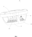
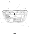
- an alarm 10 with a function of obstacle detection comprises the mounting base 11, the obstacle sensor 12, the covering 13 and the alarm sensor 15.
- the obstacle sensor 12 is mounted on the mounting base 11, the air flow passage 14 is defined between the covering 13 and the mounting base 11, the obstacle sensor 12 has a detection region and the air flow passage 14 is located within the detection region of the obstacle sensor 12.
- the alarm sensor 15 is disposed on the covering 13, the alarm sensor 15 is located within the detection region of the obstacle sensor 12.
- the air flow passage 14 provides a passage for a substance that triggers the alarm sensor 15 to reach the alarm sensor 15.
- the obstacle sensor 12 and the alarm sensor 15 are respectively disposed on the mounting base 11 and the covering 13, and both the alarm sensor 15 and the air flow passage 14 are located within the detection region of the obstacle sensor 12, so that the blind region of the obstacle sensor 12 performing the obstacle detection in the environment where the alarm sensor 15 is located is eliminated, and the obstacle sensor 12 can fully monitor obstacles in the environment where the alarm sensor 15 is located, thereby the operation reliability of the alarm 10 of the present invention can be improved.
- the obstacle sensor 12 and the alarm sensor 15 are disposed on the mounting base 11 and the covering 13, respectively, and both the alarm sensor 15 and the air flow passage 14 are located within the detection region of the obstacle sensor 12, so that the blind region for obstacle detection 12 of the obstacle sensor 12 in the environment where the alarm sensor 15 is located is eliminated, and the obstacle sensor 12 can fully monitor obstacles in the environment where the alarm sensor 15 is located, thereby improving the operation reliability of the alarm 10.
- an air flow enters the covering 13 through the air flow passage 14 so as to reach the alarm sensor 15, and the concentration of smoke particles in the air flow is detected by the alarm sensor 15.
- the air flow continuously enters the covering 13 through the air flow passage 14 and reaches the alarm sensor 15, so that the alarm sensor 15 monitors in real time the concentration of the detected object in the environment where the alarm 10 is located.
- the alarm sensor 15 monitors that the concentration of the detected object exceeds a warning value, a sound-light alarm is triggered or a radio signal is transmitted to a remote terminal to prompt the possible occurrence of relevant accidents.
- the obstacle sensor 12 is disposed on the mounting base 11, the alarm 15 is disposed on the covering 13, and the air flow passage 14 is defined between the covering 13 and the mounting base 11.
- the obstacle sensor 12 monitors obstacles in the spatial region of the mounting base 11 on the covering 13 side, so that both the air flow passage 14 and the alarm sensor 15 are located in the monitoring range of the obstacle sensor 12, the monitoring blind region of the obstacle sensor 12 is eliminated, and the obstacle sensor 12 can fully monitor the obstacle at the alarm 10.
- the obstacle When an obstacle exists near the air flow passage 14 or the alarm 10, the obstacle can be detected by the obstacle sensor 12. After the obstacle sensor 12 detects the obstacle, the alarm 10 gives an alarm to prompt the existence of the obstacle, so that an operator can remove the obstacle in time so as to eliminate the safety hazard.
- the obstacle sensor 12 may be a photoelectric sensor or an ultrasonic sensor.
- the obstacle sensor 12 emits a sensing signal to the spatial region of the mounting base 11 adjacent to the covering 13. When the sensing signal comes into contact with an obstacle, the sensing signal is reflected back to the obstacle sensor 12 by the obstacle, so that the obstacle sensor 12 can detect the existence of the obstacle.
- the alarm 10 is hung on the ceiling inside the room, the mounting base 11 is mounted adjacent to the ceiling, and the covering 13 is located on the side of the mounting base 11 away from the ceiling.
- the obstacle sensor 12 is disposed on the mounting base 11
- the alarm sensor 15 is disposed on the covering 13
- the air flow passage 14 is defined between the covering 13 and the mounting base 11.
- the obstacle sensor 12 emits a sensing signal to the covering 13, the sensing signal emitted by the obstacle sensor 12 is reflected by the obstacle, and the obstacle sensor 12 receives the reflected sensing signal, so that the strength of the reflected sensing signal received by the obstacle sensor 12 is enhanced.
- the strength of the received reflected sensing signal is enhanced, it can be determined that an obstacle exists in the air flow passage 14.
- the alarm 10 gives an alarm to prompt the existence of the obstacle, so that the operator can remove the obstacle in the air flow passage 14 and the air flow passage 14 returns to the unblocked state.
- the alarm 10 is mounted on a wall inside the room, the mounting base 11 is mounted adjacent to the wall, and the covering 13 is located on the side of the mounting base 11 away from the wall.
- the obstacle sensor 12 is disposed on the mounting base 11
- the alarm sensor 15 is disposed on the covering 13
- the air flow passage 14 is defined between the covering 13 and the mounting base 11.
- the obstacle sensor 12 emits a sensing signal toward the side of the mounting base 11 away from the wall, the sensing signal emitted by the obstacle sensor 12 is reflected by the obstacle, and the obstacle sensor 12 receives the reflected sensing signal, so that enhancing the strength of the reflected sensing signal received by the obstacle sensor 12.
- the received reflected sensing signal is enhanced, it can be determined that an obstacle exists near the alarm 10.
- the alarm 10 gives an alarm to prompt the existence of the obstacle, so that the operator can remove the debris near the alarm 10 and the smoothness of the air flow near the alarm 10 is ensured.
- the hanging plate 16 has a mounting surface for connecting to the mounting base 11. That is, the mounting base 11 is adjacent to the mounting surface, and the covering 13 is farther away from the mounting surface.
- the obstacle sensor 12 emits a sensing signal to the covering 13, so a spatial region of the mounting base 11 away from the mounting surface is located within the monitoring range of the obstacle sensor 12. That is, the air flow passage 14, the covering 13 and the alarm sensor 15 are all located within the monitoring range of the obstacle sensor 12.
- the air flow passage 14, the covering 13 and the alarm sensor 15 are in the monitoring range of the obstacle sensor 12 so that the monitoring blind region of the obstacle sensor 12 to an obstacle that blocks the alarm sensor 15 is eliminated, the obstacle sensor 12 can fully monitor obstacles in the environment where the alarm sensor 15 is located, and the operation reliability of the alarm 10 is improved.
- a reflector 131 in a conical shape is connected to the covering 13 being adjacent to the mounting base 11; the reflector 131 has a tip facing the obstacle sensor 12 and being aligned with a center of the obstacle sensor 12.
- a longitudinal section of the reflector 131 is in a conical shape with straight or curved edges.
- the signal emitted by the obstacle sensor 12 is diffused by the reflector 131 to a space where the alarm 10 is located.
- the sensing signal emitted by the obstacle sensor 12 is reflected by the reflector 131, and the sensing signal is diffused to a space near the alarm 10.
- the sensing signal will pass through the air flow passage 14 during the diffusion process.
- the blind region for obstacle detection of the obstacle sensor 12 in the environment where the alarm sensor 15 is located is eliminated, the obstacle sensor 12 can fully monitor obstacles in the environment where the alarm sensor 15 is located, and the operation reliability of the alarm 10 is improved.
- the obstacle sensor 12 emits a sensing signal.
- the sensing signal may be a beam, ultrasonic waves or electromagnetic waves.
- the obstacle sensor 12 emits a sensing signal, and the sensing signal reaches the reflector 131 and is then reflected by the reflector 131. Since the reflector 131 is in a conical shape, the sensing signal will be diffused to the space where the alarm 10 is located by the reflection surface of the reflector 131. Since the reflector 131 is connected to the covering 13 being adjacent to the mounting base 11, when the sensing signal is diffused by the reflector 131, the sensing signal will pass through the air flow passage 14 defined between the covering 13 and the mounting base 11 and is diffused to the space near the alarm 10.
- the sensing signal passes through the air flow passage 14 and is then diffused to the space near the alarm 10
- the sensing signal will be reflected by the obstacle, and a part of the sensing signal reflected by the obstacle will be received by the obstacle sensor 12, so that the strength of the reflected sensing signal received by the obstacle sensor 12 is enhanced.
- the received reflected sensing signal is enhanced, the existence of the obstacle can be monitored.
- the alarm 10 gives an alarm to prompt the existence of the obstacle, so that the operator can remove the obstacle, the smoothness of the air flow near the alarm 10 and in the air flow passage 14 is ensured, and the operation reliability of the alarm 10 is improved.
- the obstacle sensor 12 is an ultrasonic sensor.
- the ultrasonic wave has high directivity and travels a long distance in a medium, and the ultrasonic wave will be reflected by an obstacle when encountering the obstacle and then will return to the obstacle sensor 12.
- the obstacle sensor 12 motors the existence of the obstacle by receiving reflected ultrasonic wave.
- the obstacle in the environment where the alarm 10 is located and the obstacle in the air flow passage 14 are monitored.
- the alarm 10 gives an alarm to prompt the existence of the obstacle, so that the operator can remove the obstacle, and the smoothness of the air flow near the alarm 10 and in the air flow passage 14 is ensured.
- the obstacle sensor 12 comprises an emitter and a receiver.
- the emitter of the obstacle sensor 12 emits an ultrasonic wave, the ultrasonic wave encounters an obstacle, is then reflected and is received by the receiver of the obstacle sensor 12, so that the strength of the reflected sensing signal received by the obstacle sensor 12 is enhanced.
- the received reflected sensing signal is enhanced, the existence of the obstacle can be monitored.
- the obstacle in the environment where the alarm 10 is located and the obstacle in the air flow passage 14 are monitored by the obstacle sensor 12.
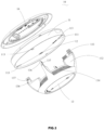
- the covering 13 has at least one support leg 132, the covering 13 is detachably connected to the mounting base 11 through the support leg 132.
- the covering 13 is mounted on the mounting base 11 through the support leg 132, and the air flow passage 14 for allowing an air flow to pass therethrough is defined between the covering 13 and the mounting base 11.
- the alarm 10 gives an alarm to the existence of the obstacle, so as to prompt the operator to remove the obstacle.
- the covering 13 can be detached from the mounting base 11, so that the obstacle is successfully removed; and, when the operator finds that an obstacle exists near the alarm 10, the operator can directly remove the obstacle near the alarm.
- the covering 13 is detached, so that the air flow passage 14 forms an open space, and the obstacle removing process is more convenient, quicker and more efficient.
- the support leg 132 having an end with a clamping structure will be arranged on an edge of the covering 13, and the mounting base 11 has a corresponding clamping slot adapted to the clamping structure of the support leg 132.
- the clamping structure of the support leg 132 is inserted into the clamping slot of the mounting base 11, so that the covering 13 and the mounting base 11 are connected.
- the air flow passage 14 for allowing the air flow to pass therethrough is defined between the covering 13 and the mounting base 11, the air flow near the alarm 10 enters the covering 13 through the air flow passage 14 and is then monitored by the alarm sensor 15, and the smoke concentration in the air flow is monitored by the alarm sensor 15.
- the air flow passage 14 has a large space for the circulation of the air flow, so that it is advantageous for the smooth flowing of the air flow. Since the space between the covering 13 and the mounting base 11 is large, in the process of removing the obstacle at the air flow passage 14, there will be less hindrance in the space, so that the operator can remove the obstacle more effectively and conveniently. When possible, in the obstacle removing process, it is unnecessary to detach the covering 13 from the mounting base 11.
- the covering 13 is supported by a plurality of support legs 132, the connection between the covering 13 and the mounting base 11 is more stable, and the possibility of relative shaking between the covering 13 and the mounting base 11 can be effectively reduced. Since the sensing signal emitted by the obstacle sensor 12 is diffused to the spatial region near the alarm 10 by the reflector 131 at the covering 13, the covering 13 is firmly mounted on the mounting base 11, and the reliability of the obstacle sensor 12 in monitoring obstacles can be effectively ensured.
- the insertion member 136 moves toward the insertion hole 113. After the insertion member 136 comes into the limiting member 114, the insertion member 136 is continuously inserted into the insertion hole 113. At this time, the insertion member 136 pushes the limiting member 114 through the wedge-shaped slope 115 at the end of the limiting member 114. The insertion member 136 continuously extends into the insertion hole 113 until the limiting hole 137 reaches a position of the limiting member 114. During this process, each limiting member 114 resists against the corresponding insertion member 136 through the spring 116. After the limiting hole 137 reaches the position of limiting member 114, the limiting member 114 is inserted into the limiting hole 137 under the action of the spring 116.
- the covering 13 is firmly mounted at the mounting base 11.
- a first circuit board is mounted on the covering 13, the alarm sensor 15 and the control circuit, the smoke alarm circuit and the like of the alarm sensor 15 are all arranged on the first circuit board and are electrically connected to an external circuit through the first port 133.
- a second circuit board is mounted on the mounting base 11, the obstacle sensor 12 and the control circuit, the obstacle alarm circuit and the like of the obstacle sensor 12 are all arranged on the second circuit board and are electrically connected to an external circuit through the second port 111.
- the external power supply supplies power to the first circuit board and the second circuit board simultaneously
- the external power supply is firstly connected to one of the first circuit board and the second circuit board and then supplies power to the other one of the first circuit board and the second circuit board.
- the external power supply is firstly connected to the first circuit board and then supplies power to the second circuit board through the first circuit board.
- the first circuit board and the second circuit board are electrically connected through the first port 133 and the second port 111.
- the electric energy is transmitted to the first circuit board through the external power supply, and then transmitted to the second circuit board through the first port 133 and the second port 111.
- the external power supply supplies power to the first circuit board and the second circuit board separately
- the external power supply is connected to the first circuit board and the second circuit board separately, and the external power supply directly supplies power to the first circuit board and the second circuit board separately.
- the power supply of the alarm 10 may also be a separate power supply, that is, at least one of the first circuit board and the second circuit board is a separate power supply capable of storing electricity.
- the circuit board with the separate power supply supplies power to the circuit board without the separate power supply through a coordination of the first port 133 and the second port 111.
- the first circuit board has a separate power supply
- the separate power supply supplies power to the first circuit board and then supplies power to the second circuit board through the coordination of the first port 133 and the second port 111.
- the covering 13 is connected to the mounting base 11 through the support leg 132, so the covering 13 comes into contact with the mounting base 11 through the support leg 132, and a part of the covering 13 beyond the support leg 132 is suspended at the mounting base 11.
- a space where the covering 13 is suspended at the mounting base 11 is defined as the air flow passage 14.
- the first port 133 is located at the support leg 132.
- the first port 133 can be connected to the second port 111 without arranging additional structures.
- a hanging plate 16 is detachably mounted on one side of the mounting base 11 away from the covering 13, and the hanging plate 16 has a mounting hole 161 on a surface of the hanging plate 16.
- the hanging plate 16 is firstly mounted at a desired position, and a combination of the mounting base 11 and the covering 13 is mounted at the hanging plate 16. During mounting the hanging plate 16, a hole is drilled at the desired position corresponding to a position of the mounting hole 161 in the hanging plate 16, the mounting hole 161 is then aligned with the drilled hole at the desired position, and the hanging plate 16 is fixedly mounted at the desired position through a screw.
- the hanging plate 16 is fixed at the desired position, and a function part formed by the combination of the mounting base 11 and the covering 13 is then mounted at the hanging plate 16.
- the functional part of the alarm 10 can be detached from the desired position by separating the covering 13 from the hanging plate 16, so that the functional part of the alarm 10 can be maintained (for example, the obstacle at the air flow passage 14 is removed).
- the functional part of the alarm 10 is remounted on the corresponding hanging plate 16 without drilling a hole again.
- the mounting hole 161 is a waist-shaped hole with a scale 162, and the number of the mounting hole 161 is at least one, and the scale 162 is arranged between adjacent mounting holes 161.
- a hole needs to be drilled at the desired position corresponding to a position of the mounting hole 161 of the hanging plate 16.
- the pitch between mounting holes 161 and the aperture can be quickly determined through the scale 162 at the mounting holes 161 of the hanging plate 16 and between the two adjacent mounting holes 161.
- the hanging plate 16 can be mounted more conveniently, accurately and quickly.
- the pitch of the drilled hole may be determined according to the scale 162 between the adjacent mounting holes 161.
- the hanging plate 16 is positioned by a plurality of mounting holes 161, and the hanging plate 16 is fixed at the desired position by using a plurality of screws, so that the hanging plate 16 is mounted firmly at the desired position.
- one of the mounting base 11 and the hanging plate 16 has a neck 163, the other one of the mounting base 11 and the hanging plate 16 has a first clamping block 112.
- a second clamping block 164 is inserted into the neck 163.
- the first clamping block 112 is capable of being slidable in the neck 163 and finally catches the second clamping block 164.
- the mounting base 11 can be mounted or detached at the hanging plate 16 quickly and conveniently.
- the mounting base 11 when the mounting base 11 is mounted at the hanging plate 16, the mounting base 11 is moved close to the hanging plate 16, and the clamping block 112 extends into the neck 163.
- the first clamping block 112 slides in the neck 163 until the clamping block 112 catches the second clamping block 164 in the neck 163.
- the mounting base 11 is mounted.
- the mounting plate 11 When it is necessary to detach the mounting base 11 from the hanging plate 16, the mounting plate 11 is rotated relative to the hanging plate 16 in a rotation direction opposite to that in mounting, and the first clamping block 112 slides in the neck 163 until the first block 112 is separated from the second clamping block in the neck 163. Then, the mounting base 11 moves away from the hanging plate 16.
- the first clamping block 112 is limited in a radial direction of the hanging plate 16 by the neck 163, and the second clamping block 164 is limited in an axial direction of the hanging plate 16 by the second clamping block 164. In this way, the mounting base 11 is detachably mounted on the hanging plate 16.
- the mounting plate 11 is rotated reversely, and the first clamping block 112 slides in the neck 163 away from the second clamping block 164 until the first clamping block 112 is separated from the second clamping block 164. In this way, the mounting base 11 is detached from the hanging plate 16.
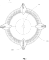
- the covering 13 has an annular edge and a top end surface adjacent to the mounting base 11; the covering 13 has an inclined surface located adjacent to the air flow passage 14 extending from the annular edge to a center of the top end surface; the covering 13 has a grid 134 on the inclined surface, and the grid 134 has a plurality of grid strips 135 successively stacked on from the annular edge to the top end surface.
- the alarm sensor 15 is disposed on the covering 13.
- the air flow circulates in the air flow passage 14 and then enters the covering 13 through the grid 134. Since the alarm sensor 15 is disposed on the covering 13, after the air flow enters the covering 13, the air flow can be monitored by the alarm sensor 15, and the smoke concentration in the air flow near the alarm 10 is monitored by the alarm sensor 15.
- the alarm sensor 15 When the alarm 10 is a smoke alarm, the alarm sensor 15 will be affected by dust, resulting in a false alarm. Therefore, by arranging the alarm sensor 15 on the covering 13, the dust is blocked by the covering 13, and the dust outside the alarm 10 is prevented from affecting the alarm sensor 15.
- the covering 13 has an annular edge and a top end surface adjacent to the mounting base 11; the covering 13 has an inclined surface located adjacent to the air flow passage 14 extending from the annular edge to a center of the top end surface; the covering 13 has a grid 134 on the inclined surface, and the grid 134 has a plurality of grid strips 135 successively stacked on from the annular edge to the top end surface, adjacent grid strips 135 are partially overlapped in a direction perpendicular to an inlet of the grid 134, and adjacent grid strips 135 extend from the annular edge to the center of the top end surface.
- the alarm 10 is generally hung on the ceiling.
- the hanging plate 16 is firstly mounted on the ceiling, the covering 13 is then mounted on the mounting base 11, and the combination of the covering 13 and the mounting base 11 is mounted on the hanging plate 16.
- the mounting base 11 is located above the covering 13, and the top end surface of the covering 13 faces toward the mounting base 11. Therefore, the top end surface of the covering 13 faces upward. Due to the gravity, the dust will fall on the top end surface of the covering 13. Since the grid 134 is opened in the direction of the side of the covering 13 and not opened in the direction of the top end surface of the covering 13, the duct cannot fall into the covering 13 through the grid 134.
- the accumulated dust can be effectively prevented from entering the covering 13 through the grid 134 and thus affecting the alarm sensor 15, and the reliability of the alarm 10 is further improved.
Landscapes
- Business, Economics & Management (AREA)
- Emergency Management (AREA)
- Physics & Mathematics (AREA)
- General Physics & Mathematics (AREA)
- Chemical & Material Sciences (AREA)
- Analytical Chemistry (AREA)
- Fire Alarms (AREA)
- Emergency Alarm Devices (AREA)
Applications Claiming Priority (2)
| Application Number | Priority Date | Filing Date | Title |
|---|---|---|---|
| CN202211390376.9A CN115683967A (zh) | 2022-11-08 | 2022-11-08 | 具有障碍物检测功能的报警器 |
| PCT/CN2022/143179 WO2024098536A1 (fr) | 2022-11-08 | 2022-12-29 | Alarme avec fonction de détection d'obstacle |
Publications (2)
| Publication Number | Publication Date |
|---|---|
| EP4530604A1 true EP4530604A1 (fr) | 2025-04-02 |
| EP4530604A4 EP4530604A4 (fr) | 2025-09-03 |
Family
ID=85050164
Family Applications (1)
| Application Number | Title | Priority Date | Filing Date |
|---|---|---|---|
| EP22965000.7A Pending EP4530604A4 (fr) | 2022-11-08 | 2022-12-29 | Alarme avec fonction de détection d'obstacle |
Country Status (4)
| Country | Link |
|---|---|
| EP (1) | EP4530604A4 (fr) |
| CN (1) | CN115683967A (fr) |
| AU (2) | AU2022485742B2 (fr) |
| WO (1) | WO2024098536A1 (fr) |
Families Citing this family (1)
| Publication number | Priority date | Publication date | Assignee | Title |
|---|---|---|---|---|
| CN119672894B (zh) * | 2025-02-21 | 2025-04-25 | 武夷山香江茶业有限公司 | 一种茶叶加工用车间烟雾报警器 |
Family Cites Families (15)
| Publication number | Priority date | Publication date | Assignee | Title |
|---|---|---|---|---|
| DE102008014991B3 (de) * | 2008-03-19 | 2009-03-12 | Job Lizenz Gmbh & Co. Kg | Verfahren und Warnmelder, insbesondere Rauchmelder |
| US7791475B2 (en) * | 2008-03-26 | 2010-09-07 | Honeywell International Inc. | Apparatus and method of blockage detection |
| DE102009047531A1 (de) * | 2009-12-04 | 2011-06-09 | Atral- Secal Gmbh | Rauchmelder mit Ultraschall-Abdecküberwachung |
| RS53300B (sr) * | 2011-02-28 | 2014-08-29 | Hager Controls | Uređaj za detektovanje prepreka koje mogu da zaklone detektor dima |
| JP6022801B2 (ja) * | 2012-04-17 | 2016-11-09 | ホーチキ株式会社 | 感知器システム、感知器及び取外治具 |
| EP2879104B2 (fr) * | 2013-11-27 | 2022-05-11 | Siemens Schweiz AG | Dispositif auxiliaire pour un détecteur de danger configuré sous forme de détecteur ponctuel pour la surveillance du fonctionnement du détecteur de danger, agencement et utilisation d'un tel dispositif |
| DE102015110393B4 (de) * | 2015-06-29 | 2026-03-12 | Sept-S Sas | Rauchmelder mit Infrarot-Lichtring-Abdecküberwachung |
| CN205845281U (zh) * | 2016-07-21 | 2016-12-28 | 真诺测量仪表(上海)有限公司 | 用于烟雾报警器烟道阻塞检测的传感器安装结构 |
| CN206441309U (zh) * | 2017-02-22 | 2017-08-25 | 宁波金盾电子工业股份有限公司 | 一种烟雾报警器带屏蔽罩的迷宫结构 |
| CN109215277B (zh) * | 2018-11-21 | 2021-12-17 | 应镇阳 | 一种智能城市用火警报警装置 |
| EP3671680A1 (fr) * | 2018-12-18 | 2020-06-24 | Siemens Schweiz AG | Détecteur d'incendie ou de fumée |
| EP4174812B1 (fr) * | 2019-04-02 | 2024-07-03 | E.I. Technology Unlimited Company | Détecteurs à ultrasons |
| CN212966445U (zh) * | 2020-09-17 | 2021-04-13 | 深圳世纪物联有限公司 | 具有报警功能的智能温湿度探测器 |
| CN113362558A (zh) * | 2021-05-12 | 2021-09-07 | 浙江华消科技有限公司 | 烟雾报警器的复位方法、烟雾报警器和电子装置 |
| CN219142578U (zh) * | 2022-11-08 | 2023-06-06 | 赛特威尔电子股份有限公司 | 具有障碍物检测功能的报警器 |
-
2022
- 2022-11-08 CN CN202211390376.9A patent/CN115683967A/zh active Pending
- 2022-12-29 EP EP22965000.7A patent/EP4530604A4/fr active Pending
- 2022-12-29 AU AU2022485742A patent/AU2022485742B2/en active Active
- 2022-12-29 WO PCT/CN2022/143179 patent/WO2024098536A1/fr not_active Ceased
-
2025
- 2025-12-16 AU AU2025283455A patent/AU2025283455A1/en active Pending
Also Published As
| Publication number | Publication date |
|---|---|
| CN115683967A (zh) | 2023-02-03 |
| AU2022485742A1 (en) | 2024-08-08 |
| AU2022485742B2 (en) | 2026-01-22 |
| EP4530604A4 (fr) | 2025-09-03 |
| WO2024098536A1 (fr) | 2024-05-16 |
| AU2025283455A1 (en) | 2026-01-22 |
Similar Documents
| Publication | Publication Date | Title |
|---|---|---|
| US7262705B2 (en) | Recessed detector assembly for detecting and venting airborne substances | |
| US8232885B2 (en) | Photoelectric smoke detector | |
| AU2025283455A1 (en) | Alarm with Obstacle Detection Function | |
| US10024782B2 (en) | Smoke chamber and smoke detector using the same | |
| TW501078B (en) | Stray light detector | |
| US10950113B2 (en) | Alarm device | |
| CN101300610A (zh) | 用于电气设备箱中的火灾检测的装置 | |
| US11385211B2 (en) | Detector | |
| CN112055872B (zh) | 用于多波多角烟雾检测器的烟雾室 | |
| US10943453B2 (en) | Alarm apparatus | |
| US20210096071A1 (en) | Smoke detector | |
| CN219142578U (zh) | 具有障碍物检测功能的报警器 | |
| US20230417665A1 (en) | Fire detection apparatus | |
| JP2008108140A (ja) | 煙感知装置 | |
| JP2010086378A (ja) | 光電式煙感知器 | |
| CN213149942U (zh) | 烟雾传感器件 | |
| CN212724272U (zh) | 烟雾检测装置 | |
| CN210006175U (zh) | 烟雾报警器 | |
| CN206893056U (zh) | 剧院的早期烟雾探测报警系统 | |
| EP4266280A1 (fr) | Dispositif de détection d'incendie | |
| CN221040197U (zh) | 一种独立式火灾报警探测器 | |
| RU240756U1 (ru) | Извещатель пожарный аспирационный | |
| JP7798876B2 (ja) | 火災検出装置 | |
| JP4999812B2 (ja) | 火災警報器 | |
| JP2020035296A (ja) | 火災検出装置 |
Legal Events
| Date | Code | Title | Description |
|---|---|---|---|
| STAA | Information on the status of an ep patent application or granted ep patent |
Free format text: STATUS: THE INTERNATIONAL PUBLICATION HAS BEEN MADE |
|
| PUAI | Public reference made under article 153(3) epc to a published international application that has entered the european phase |
Free format text: ORIGINAL CODE: 0009012 |
|
| STAA | Information on the status of an ep patent application or granted ep patent |
Free format text: STATUS: REQUEST FOR EXAMINATION WAS MADE |
|
| 17P | Request for examination filed |
Effective date: 20241223 |
|
| AK | Designated contracting states |
Kind code of ref document: A1 Designated state(s): AL AT BE BG CH CY CZ DE DK EE ES FI FR GB GR HR HU IE IS IT LI LT LU LV MC ME MK MT NL NO PL PT RO RS SE SI SK SM TR |
|
| A4 | Supplementary search report drawn up and despatched |
Effective date: 20250731 |
|
| RIC1 | Information provided on ipc code assigned before grant |
Ipc: G01N 15/06 20240101AFI20250725BHEP Ipc: G08B 17/06 20060101ALI20250725BHEP Ipc: G08B 17/10 20060101ALI20250725BHEP Ipc: G08B 17/113 20060101ALI20250725BHEP Ipc: G01N 15/00 20240101ALI20250725BHEP Ipc: G01S 15/04 20060101ALI20250725BHEP Ipc: G01S 15/88 20060101ALI20250725BHEP Ipc: G08B 29/18 20060101ALI20250725BHEP |
|
| DAV | Request for validation of the european patent (deleted) | ||
| DAX | Request for extension of the european patent (deleted) |