EP4530602A1 - Vorrichtung und verfahren zur verarbeitung biologischer proben - Google Patents
Vorrichtung und verfahren zur verarbeitung biologischer proben Download PDFInfo
- Publication number
- EP4530602A1 EP4530602A1 EP24217549.5A EP24217549A EP4530602A1 EP 4530602 A1 EP4530602 A1 EP 4530602A1 EP 24217549 A EP24217549 A EP 24217549A EP 4530602 A1 EP4530602 A1 EP 4530602A1
- Authority
- EP
- European Patent Office
- Prior art keywords
- slide
- chamber
- capillary
- fluid
- processing module
- Prior art date
- Legal status (The legal status is an assumption and is not a legal conclusion. Google has not performed a legal analysis and makes no representation as to the accuracy of the status listed.)
- Pending
Links
Images





Classifications
-
- G—PHYSICS
- G01—MEASURING; TESTING
- G01N—INVESTIGATING OR ANALYSING MATERIALS BY DETERMINING THEIR CHEMICAL OR PHYSICAL PROPERTIES
- G01N1/00—Sampling; Preparing specimens for investigation
- G01N1/28—Preparing specimens for investigation including physical details of (bio-)chemical methods covered elsewhere, e.g. G01N33/50, C12Q
- G01N1/30—Staining; Impregnating ; Fixation; Dehydration; Multistep processes for preparing samples of tissue, cell or nucleic acid material and the like for analysis
- G01N1/31—Apparatus therefor
- G01N1/312—Apparatus therefor for samples mounted on planar substrates
-
- G—PHYSICS
- G01—MEASURING; TESTING
- G01N—INVESTIGATING OR ANALYSING MATERIALS BY DETERMINING THEIR CHEMICAL OR PHYSICAL PROPERTIES
- G01N35/00—Automatic analysis not limited to methods or materials provided for in any single one of groups G01N1/00 - G01N33/00; Handling materials therefor
- G01N35/00029—Automatic analysis not limited to methods or materials provided for in any single one of groups G01N1/00 - G01N33/00; Handling materials therefor provided with flat sample substrates, e.g. slides
-
- G—PHYSICS
- G01—MEASURING; TESTING
- G01N—INVESTIGATING OR ANALYSING MATERIALS BY DETERMINING THEIR CHEMICAL OR PHYSICAL PROPERTIES
- G01N35/00—Automatic analysis not limited to methods or materials provided for in any single one of groups G01N1/00 - G01N33/00; Handling materials therefor
- G01N35/00584—Control arrangements for automatic analysers
-
- G—PHYSICS
- G01—MEASURING; TESTING
- G01N—INVESTIGATING OR ANALYSING MATERIALS BY DETERMINING THEIR CHEMICAL OR PHYSICAL PROPERTIES
- G01N35/00—Automatic analysis not limited to methods or materials provided for in any single one of groups G01N1/00 - G01N33/00; Handling materials therefor
- G01N35/00029—Automatic analysis not limited to methods or materials provided for in any single one of groups G01N1/00 - G01N33/00; Handling materials therefor provided with flat sample substrates, e.g. slides
- G01N2035/00039—Transport arrangements specific to flat sample substrates, e.g. pusher blade
-
- G—PHYSICS
- G01—MEASURING; TESTING
- G01N—INVESTIGATING OR ANALYSING MATERIALS BY DETERMINING THEIR CHEMICAL OR PHYSICAL PROPERTIES
- G01N35/00—Automatic analysis not limited to methods or materials provided for in any single one of groups G01N1/00 - G01N33/00; Handling materials therefor
- G01N2035/00346—Heating or cooling arrangements
- G01N2035/00425—Heating or cooling means associated with pipettes or the like, e.g. for supplying sample/reagent at given temperature
-
- G—PHYSICS
- G01—MEASURING; TESTING
- G01N—INVESTIGATING OR ANALYSING MATERIALS BY DETERMINING THEIR CHEMICAL OR PHYSICAL PROPERTIES
- G01N35/00—Automatic analysis not limited to methods or materials provided for in any single one of groups G01N1/00 - G01N33/00; Handling materials therefor
- G01N35/02—Automatic analysis not limited to methods or materials provided for in any single one of groups G01N1/00 - G01N33/00; Handling materials therefor using a plurality of sample containers moved by a conveyor system past one or more treatment or analysis stations
- G01N35/04—Details of the conveyor system
- G01N2035/0401—Sample carriers, cuvettes or reaction vessels
- G01N2035/0403—Sample carriers with closing or sealing means
- G01N2035/0405—Sample carriers with closing or sealing means manipulating closing or opening means, e.g. stoppers, screw caps, lids or covers
Definitions
- the present invention relates to apparatus and methods for processing a biological sample on a slide using a capillary processing module.
- Sample processing for analyses in histology, cytology, molecular pathology, biochemistry, immunology, microbiology, and other chemical and biological analyses may involve one or a number of processing steps on the sample. Samples may be placed on slides before performing some or all of the desired processing steps. For example, a sample on a slide may be contacted with one or more reagents to label a component of the sample and/or to undergo a reaction with a component of the sample. A wide variety of processing steps are known in these fields and/or may be developed for a particular analysis to be performed.
- crank refers to any mechanism or device that converts rotary motion to linear motion and/or vice versa.
- a crank generally comprises a shaft configured for rotation, and a portion that travels in a wider arc than another portion of the shaft.
- the bent portion is bent out at right angles, as illustrated in FIG. 4 .
- the bent portion can be open or it can form a closed loop.
- the crank may comprise an arm that is rotated or engages an actuator for rotation.
- the arm may integral with the shaft, or it may be a separate piece attached to the shaft.
- the crank can be rotated directly or indirectly, such as where the arm is physically contacted and a rotary force is applied, or where a magnetic force causes the shaft to rotate.
- Rotation of the crank may comprise a full rotation or a partial rotation such as over a limited arc, and includes moving the shaft back and force less than a full rotation, such as by turning about 90° or a larger or small arc.
- the shaft has a portion having a cross-sectional shape which is circular, elliptical, oval-shaped, or non-circular.
- Various shapes can be appropriately selected for use, such as oblong, polygonal, square, rectangular.
- the crank typically comprises a bearing
- the chamber typically comprises a bearing hole on one or two chamber sidewalls on opposite sides of CPM.
- the bearing holes can be through-holes or dead-end holes, and a CPM may have one of each.
- the crank can comprise one or more journals or portions of a shaft specially configured to contact a bearing.
- the crank can also comprise one more bushings inserted into the chamber hole to provide a bearing surface for the journal. In some embodiments, the crank extends from the one or more chamber sidewalls and does not extend through the chamber floor.
- the crank is configured in the CPM so that the shaft's rotation raises and lowers the slide. Because a portion of shaft (such as a bent or asymmetric portion) engages the slide to raise it, the portion may have a coating or surface treatment to reduce friction with the slide. Alternatively, the coating or surface treatment may increase friction or enhance engagement, allowing a biasing force to be applied to the slide by the crank. In some embodiments, the shaft forms a closed loop, which may be rectangular or another shape.
- a “slide” refers to any sample holder, support or substrate having at least one substantially flat surface for a biological or chemical sample.
- the slide can be a carrier, test tube, chip, array, or disk that can support at least one sample.
- a slide typically has first and second major slide surfaces.
- a sample may be disposed on a slide in various ways.
- the sample is a biological sample such as a layer or slice of skin, tumor, or other tissue.
- the tissue or other sample may be preserved in formaldehyde or in an embedding medium such as paraffin. Samples in paraffin or other embedding medium may be subjected to steps like deparaffinization, by which paraffin overlaying and/or infiltrating the sample is removed.
- the present disclosure refers to a capillary processing module (CPM), which also encompasses a capillary staining module or other module for performing one or more processing steps as described herein.
- CPM capillary processing module
- the present methods and apparatus generally make use of a CPM as described herein.
- the CPM comprises a chamber for receiving a slide and performing one or more processing steps on the slide.
- the chamber can be any desired shape or size and can be formed from any desired material.
- the chamber is substantially rectangular with a longer side and a shorter side.
- the CPM can also include a chamber inlet through which fluids (such as a liquid comprising reagent) are introduced to the chamber for processing the sample.
- the chamber inlet is on the longer side; In some embodiments, the longer slide is about three times longer than the shorter side
- the chamber can have an open top, and the CPM can comprise a chamber lid that closes the chamber.
- the chamber can have one or more regions. In some embodiments, a processing area is located in a first region, and a crank is located in a second region.
- the CPM is made of a stainless steel alloy (such as SMO254) treated by surface hardening, such as Kolsterising, to resist scratching.
- a surface of the CPM comprises an inert, corrosion resistant coating, such as a barrier of amorphous silicon, oxygen and carbon.
- the coating can be selected to provide one or more of corrosion and wear resistance, chemical inertness, and anti-stick properties.
- the coating may be an inert corrosion resistant coating such as Dursan.
- Such coatings can prevent or reduce residue left on the bottom surface of the CPM, such as tissue residues and staining residues.
- the coating can be applied to the surface of the CPM by any suitable technique, such as by chemical vapor deposition (CVD).
- automated is defined as a plurality of steps that are executed by substantially mechanical, computer and/or electronic means, though it does not exclude some human intervention steps such as manually replacing one of the described features or steps.
- an automated sample processing apparatus also refers to an automated staining apparatus or other automated apparatus performing one or more steps of sample processing.
- a slide is inserted in an automatic fashion into the CPM for processing and then removed from the CPM after one or more processing steps in the CPM have been performed.
- the slide insertion and/or removal can be performed by, for example, a slide gripper on a robotic arm, and so the present apparatus and methods can further comprise an automated system for movement of an individual slide.
- the raising of the slide to an angle (for example, a fixed angle of 11°) by the crank of the CPM allows for automated removal of the slide by the slide gripper without the mechanic tolerances of the slide gripper or robotic arm making the removal of the slide infeasible or impractical.
- the present methods and apparatus are advantageous in their slide handling capabilities.
- the chamber can be opened to receive a slide and closed after the slide is inserted.
- the chamber provides space (i.e., the recess) to accommodate a gripper that is holding a slide at its end label as it inserts the slide into the chamber.
- the CPM also produces agitation to present the slide, and it has features to force the slide to a desired position within the chamber, such as one or more catches in the X, Y, and/or Z directions. By rotating the crank, the slide can be biased in the Y direction toward an end of the chamber.
- the CPM can have one or more guide pins to bias the slide in the X direction.
- camera teach points are included to facilitate automation and machine learning.
- the present apparatus and methods can employ a crank positioned in a CPM to raise and lower a slide or a portion of a slide.
- the crank can be any design suitable for converting motion from one dimension or direction to another, particularly for converting rotational motion to linear motion.
- the crank can be configured to convert rotary motion to linear motion in a direction substantially perpendicular to a major surface of a slide.
- FIG. 1A to 1D provide a conceptual illustration of how a crank can be configured to raise and lower a slide 102.
- the crank comprises a shaft 106 which is configured to rotate on axis 107 so that bent portion 108 engages or disengages slide 102.
- FIGs. 1A and 1C provide views from a long edge of slide 102, and FIGs.
- FIGs. 1A and 1B show a slide 102 in a lowered position with respect to a chamber floor 104 of a CPM.
- FIGs. 1C and 1D slide 102 is raised with respect to a chamber floor 104 of a CPM by rotation of shaft 106.
- Shaft 106 comprises a bent portion 108 which engages slide 102 to raise it.
- Shaft 106 is configured for rotation around an axis extending horizontally in the plane of the figure.
- shaft 106 has been rotated about 180° or half a turn, so that bent portion 108 is above chamber floor 104 and engages or raises slide 102.
- Rotating can also control biasing in x-direction (the long side) by the vertical side walls of the crank.
- bent portion can be disposed in recess 109 of the CPM into which bent portion 108 can extend below the plane of chamber floor 104 and/or the axis of rotation of shaft 106.
- Chamber floor 104 is separated from recessed floor 109 by an inclined floor 111.
- FIGs. 1A and 1C also illustrate how a capillary gap can be formed and broken between slide 102 and chamber floor 104.
- a capillary gap is present, having a height defined by the height of slide supports 117 and 118 upon which slide 102 rests when in its lowered position.
- a capillary gap is a distance between two surfaces sufficient to permit capillary action between the surfaces.
- Capillary action also referred to as capillary effect or wicking
- Capillary action is the flowing or movement of liquid in narrow spaces due to intermolecular forces between the liquid and solid surfaces.
- the CPM is configured to provide a capillary gap from about 0.01 mm to about 0.3 mm, alternatively from about 0.07 mm to about 0.1 mm, between a chamber floor and a slide in a lowered position, and/or to provide a capillary gap volume from about 10 ⁇ L to about 300 ⁇ L, alternatively from about 80 ⁇ L to about 100 ⁇ L.
- the sample attached to the slide is facing downwards and the capillary gap is defined by the slide and the geometry of the CPM. More particularly, the sample is attached to a first major slide surface, and the method comprises inserting the slide into the chamber such that the first major slide surface having the sample faces the chamber floor.
- the shape of the slide, the geometry of the CPM, material surface properties, slide lifting velocity, angle of slide and properties of the applied or fluid(s) are factors that control the behavior of the fluids applied to the sample in the CPM.
- the slide 102 is in a raised position, and capillary gap is not present, as it has been broken by operating the crank to raise the slide 102 to increase its distance from the chamber floor 104.
- Slide 102 does not contact slide support 118, though it may remain in contact with slide support 117, or it may contact chamber floor 104 or another portion of the chamber such as a back wall.
- the breaking of the capillary gap, while still retaining control of the processing fluid and being able to regenerate the capillary gap are a substantial advantage.
- the crank to raise and lower a slide after applying a liquid enables mixing of a reagent and small liquid reagent volumes such as 50 to 150 ⁇ L can be used without local depletion of the reagent.
- the slide can be raised to a specific height and/or angle, and at a speed in a controlled fashion, such that mixing of the reagent in the applied fluid and buffer can be performed with small reagent volumes such as 90 ⁇ L as well as larger buffer volumes such as 2000 ⁇ L. Washing efficiency is increased when mixing can be performed during the staining protocol washing steps.
- FIGs. 2A to 2D illustrate another embodiment of the present apparatus and methods, where bent portion 128 has a width greater than the width of slide 122 and where rotation axis is above slide 122.
- crank is configured to receive or hold slide 122 within its bent portion 128.
- the CPM can raise or lower slide 122 over a broader range of angles.
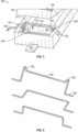
- FIG. 3 provides a perspective view of a CPM 140 according to the present disclosure.
- CPM has a housing 141 and a lid 143, and when lid 143 is in a lowered position, a closed chamber is formed.
- Shaft 146 extends through a bearing hole into chamber defined by chamber floor 144 of housing 141 and lid 143.
- Housing 141 has a recess 149 to accommodate bent portion 148 of the crank when it is in a lowered position, in that shaft 146 can be rotated until bent portion 148 is disposed in the recess 149 and does not extend above chamber floor 144.
- Shaft 146 is supported in bearing holes by bearings 151, 152 which allow rotation.
- Housing 141 has an inclined floor 153 leading from chamber floor 144 into recess 149.
- crank provides an advantage that is not readily apparent, in that it facilitates the creation of a chamber that is sealed or closed from the ambient environment.
- the present apparatus avoids the use of a lifting mechanism or a power line that breaches or travels into the CPM chamber from the outside environment. Nor does it require that the power source providing the lifting force is placed inside the CPM chamber or to use magnetic forces to drive the movement. If a mechanism goes through the bottom of the CPM, then it has to be well sealed to avoids leaks and potential damage of the chamber. Further, glass residuals, dirt and liquids may fall into a lifting mechanism on the bottom and potentially cause damage.
- the present apparatus with its crank located on a side wall of the chamber, avoids these issues.
- the present apparatus employs a relatively simple mechanic rotation to control the raising of a slide to a desired height in CPM. Using tangential forces, the slide can be actively moved such that it is biased or unbiased, depending of design and rotation direction.
- the present apparatus also reduces or avoids demands of high precision in inserting slides to a processing position by a robot, as the crank and wall(s) of the CPM cause the slide to be biased into the desired position for processing.
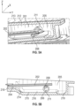
- FIGs. 5A, 5B and 5C show another embodiment of the present apparatus and methods.
- Slide 202 is raised and lowered by a crank in the CPM.
- the crank comprises an asymmetric portion 208 that engages slide 202.
- An asymmetric portion 208 can be made by cutting away or omitting a portion of shaft 206.
- a shaft has an asymmetric portion that engages the slide, such as an elliptical, oval, or eccentric shaft.
- Shaft 206 is supported by bearing 211 in a sidewall 205 of a chamber 201. Chamber 201 is closed by a chamber lid 212, forming an isolated space for processing slide 202.
- Shaft 206 is configured so that, even when slide 202 is raised to its most raised position, slide 202 does not physically contact chamber lid 212.
- a heater 213 is in thermal contact with chamber lid 212. As shown in FIG. 5A , heater 213 is a plate covering substantially all of the area of a first side of chamber lid 212. Heaters can also be provided on the bottom of the chamber 201. Heater 213 can provide substantially uniform heat to chamber lid 212 and to chamber 201.
- Chamber 201 has a chamber floor 204, and when shaft 206 and asymmetric portion 208 are rotated so that slide 202 is in a lowered position (as generally illustrated in FIG. 5A ), the slide 202 and the chamber floor are separated by a small gap.
- the gap may be provided by supporting the slide a small distance above the chamber floor 204 by one or more support posts extending from chamber floor 204.
- Chamber 202 can also comprise an inclined floor 214 extending from chamber floor 204 to a recessed floor 215 in the direction of shaft 206, so that chamber 201 has a recess 216 that can accommodate shaft 206 or a portion thereof.
- Sidewall 205 joins chamber floor 204 at a curved corner 218 having a curvature.
- Other surfaces of chamber 201 can also be joined to sidewall 205 at a curved corner 219 which may have a different curvature or other characteristics than corner 218. Curved corners facilitate complete removal of processing fluids from chamber 201.
- the CPM can have one or more chamber sidewalls are joined to the chamber floor by a curved corner having a radius of curvature from about 0.5mm to about 5mm.
- FIG. 5C shows a cross-section of the crank where an asymmetric portion 208 is between bearings 211, 221.
- the crank includes a drive end 222 which has on or more features to engage a drive that rotates the crank.
- the drive end 222 engages gear 223, which can be rotated by a drive chain 224 or other actuating mechanism.
- Drive end 222 and gear 223 may have reciprocal features or may be fastened in another way.
- compression springs 225 are positioned between gear 223 and drive end 222 so that a suitable force is applied (for example, about 2.6N), thereby sealing the chamber 201 from a surrounding environment.
- the present methods and apparatus are advantageous in providing a defined staining area based on slide position and liquid position within the chamber.
- the staining area can also be defined in part by a ramp, a slide edge, and/or a label on the slide.
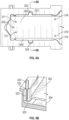
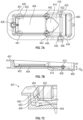
- FIGs. 6A to 6F illustrate another embodiment of the present apparatus and methods, particularly various elements of a chamber 301 of a CPM.
- Slide 302 is positioned in a chamber 301 that comprises a chamber floor 304 and an inclined floor 314. Support posts 317, 318 support slide 302 a short distance above chamber floor 304.
- Chamber 301 defines a slide space capable of receiving a slide 302.
- Slide space has an area defined by chamber length L C and chamber width W C .
- L C is from about 74 mm to about 106 mm (for example, about 90 mm)
- W C is from about 24 mm to about 36 mm (for example, about 30 mm).
- Chamber 302 can also define a processing area A P defined by processing length L P and processing width W P , which is the area covered by a processing fluid spread by capillary force between slide 302 and chamber floor 304.
- L P is from about 42 mm to about 54 mm (for example, about 48 mm)
- W P is from about 26 mm to about 32 mm (for example, 29 mm); and/or A P is from about 1000 mm 2 to about 1800 mm 2 (for example, about 1400 mm 2 ).
- Processing width W P is substantially the same as slide width Ws, as the capillary gap is defined by the slide's surface.
- Processing length L P is defined by length of chamber floor 304, since the capillary gap is broken by inclined floor 314.
- the present methods and apparatus also have excellent liquid dispensing capabilities and features, such as by having a port to allow addition of liquid to the chamber without opening the chamber lid.
- the CPM can have one or more inlets, which are configured to accommodate tip position of a dispenser such as a pipette, including tolerances for the dispenser.
- the inlets can be configured to prevent liquid from being trapped, and to connect to the capillary gap formed by the slide and the chamber floor.
- the inlet has a rounded area and/or has a volume below a slide present in the chamber.
- the features for dispensing liquid include one or more apertures on the chamber floor or a chamber side which can be connected to a conduit that delivers liquid from outside, such as a wash buffer.
- the CPM enables faster dispensing of a liquid into a processing area.
- the CPM is configured to provide a capillary gap between the slide and the chamber floor, more specifically in a planar processing area.
- the CPM can have 3 knobs extending from the chamber floor (or a different number of knobs), wherein the slide rests on the knobs. The height of the knobs establishes the height of the capillary gap.
- Other features can be included in the CPM to facilitate the use of capillary forces to distribute fluid in the processing area of the chamber.
- pipette teach points are included to facilitate automation and machine learning.
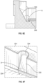
- FIG. 6B is a cut-through view along the line indicated in FIG. 6A , and it illustrates how a processing fluid can be dispensed to slide 302, which is in a raised position.
- Slide 302 can be raised by a crank as described herein or by another mechanism.
- a fluid dispenser 320 is inserted into chamber inlet 322.
- the fluid is dispensed when the slide is in a raised position, or while the slide is being lowered from a raised position.
- chamber inlet 322 is located along the long side of chamber 301, though it can be located at a short side, in addition to or instead of the long side.
- Fluid can be dispensed when the slide is in a lowered positions, and fluid will be drained from the inlet by capillary forces during dispensing. If fluid is dispensed when the slide is raised, then the slide is lowered after dispense to spread fluid across processing area. Before or after dispensing a fluid, slide 302 can raised to a height or angle sufficient to avoid or break capillary forces between slide 302 and chamber floor 304. Some fluid from dispenser 320 may stay in inlet 322 but a portion is partially forced out below the slide 302 by dispensing pressure.
- fluid is dispensed as a series of droplets, and the fluid may begin spreading across the processing area before all the fluid is dispensed, though a portion of the fluid should remain in the inlet as each subsequent droplet is added.
- the rate of dispensing and the rate of spreading in the processing area should be balanced, and dispensing should be done at an appropriate speed or rate.
- the fluid should not be dispensed so quickly that a portion splashes or flows onto the top surface of the slide.
- the rate at which a fluid is dispensed into an inlet is based on a liquid class for the fluid.
- Examples of dispensing rates for various liquid classes include 0.1mL/s to 1mL/s for liquids having viscosities like water (about 1 centipoise at 20 °C), and as low as 0.01mL/s for liquids having higher viscosities, such as in situ hybridization buffers.
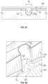
- FIGs. 6C and 6D show more detail of chamber inlet 322.
- the flat design of chamber inlet 322 is configured for forming a major drop of dispensed fluid at the floor of the inlet. The drop is restrained from spreading.
- Dimension ⁇ for instance, 4.5
- inlet width W I for example, 4.5 mm
- Inlet wall 323 is joined to inlet floor 325 by an outward curved corner 328, wherein the curve has a radius R1 (for instance, R1 can be 1.45mm).
- R1 is selected to ensure that substantially no fluid remains in the chamber inlet when the fluid is caught by the increasing capillary forces of the lowering slide.
- D1 (for example, 6.3 mm) is the distance from the far wall to a small slide (such as a slide that is 24.43 mm wide), which corresponds to how far the fluids have to reach.
- Chamber 301 has a sidewall joined to its chamber floor by an outward curved corner 329 having a radius R2 (for instance, R2 can be 0.8mm).
- D2 (for example, 4.47 mm) is distance from chamber wall to the slide edge when closest to the inlet. D2 can be selected to secure that dispenser does not touch the slide edge when the slide is closest to the inlet. It will be appreciated that ⁇ ,W I , R1, D1, R2, and D2 may have dimensions other than the exemplary dimensions set forth above.
- Some embodiments of the CPM are configured to have a tight contact of the chamber lid with the chamber.
- the CPM can be designed so that the chamber lid has planar overlap (in the X-Y plane) with the chamber.
- the chamber lid (either directly or through the frame attached to the chamber lid) can be spring loaded in the Z dimension to ensure tight contact with the chamber, and the chamber lid can also be configured so to have a floating suspension in the Z dimension, as illustrated in FIGs. 9A to 9C .
- the present methods can comprise one or more of the following processing steps: baking at 75°C ⁇ 2°C; dewaxing at 60°C ⁇ 2°C to dissolve paraffin or other embedding medium in a solvent, followed by washing with EtOH; TR at 97°C ⁇ 2°C, such as by TR by HIER in a TR buffer, following by washing with WB/DI; IHC at 37°C ⁇ 2°C, such as by contacting the sample with Envision Flex+: pAB, Block, Linker, HRP, DAB, followed by washing with WB; counter staining, such as by contacting the sample with DI, HTX, DI, WB; IF at 37°C ⁇ 2°C, such as by IF: pAB, and washing with WB.
- the present methods can comprise one or more steps of CISH assays at 37°C ⁇ 2°C, such as blocking of sample endogeneous enzymatic activity, incubation with enzyme conjugated antibodies, deposition of tracers or chromogens, visualization of tracers by chromogens and other relevant processing steps. Wash with WB; wash buffermounting at 37°C ⁇ 2°C, and dehydration in EtOH; and cleaning at 37°C ⁇ 2°C, with incubation in NaClO, and wash with WB. wash buffer or water
- the present apparatus and methods may be used in the fields of cytology, histology, molecular pathology, biochemistry, immunology, microbiology, cell biology, molecular cytogenetics and immunohistochemistry, and accordingly, the methods can comprise one or more processing procedures employed in those fields.
- the present methods and apparatus can comprise one or more processes or fluids for processing biological samples in immunohistochemistry (IHC), in-situ hybridization (ISH), fluorescent in-situ hybridization (FISH), chromogenic in-situ hybridization (CISH), special stains (SS), silver in-situ hybridization (SISH), microarrays (tissue, protein, RNA, DNA, PNA, LNA, etc.) as well as other chemical and/or biological applications.
- IHC immunohistochemistry
- ISH in-situ hybridization
- FISH fluorescent in-situ hybridization
- CISH chromogenic in-situ hybridization
- SS special stains
- SISH silver in-situ hybridization
- the present methods may comprise contacting the sample with a plurality of different fluid reagents or wash fluids.
- the sample is subjected to processing processes in the CPM such as deparaffinization, washing, antigen retrieval, endogenous biotin or enzyme blocking, incubation with immunological reagents, molecular probes, secondary visualization reagents and various chromogen reagents, washing steps and counterstaining.
- the present methods can comprise raising a slide by rotating a crank before applying the second fluid reagent; lowering the slide by rotating the crank, thereby spreading the second fluid reagent across a processing area of the slide; raising the slide by rotating the crank, thereby withdrawing the second fluid reagent; and removing the second fluid reagent from the processing area.
- the foregoing processes can be performed with a third fluid reagent, a fourth fluid reagent, and so on, up to ten, twelve, or any other desired number of fluid reagents.
- the foregoing processes can be performed with one or more wash fluids in place of the fluid reagent.
- a tissue staining apparatus can comprise a CPM as described herein which is connected (directly or indirectly) to one or more of a controller, a pipettor for dispensing fluids, a robotic arm for grasping and moving a slide, reagent vials, and apparatus for storing and/or moving the reagent vials.
- the tissue staining apparatus can include one or more controllers configured or programmed for operation of the crank, the chamber lid, the pump, the heater(s), the cooling device(s), and/or other features of the CPM.
- the controllers can comprise hardware, software, or a combination of hardware and software for operation of the components of the system.
- the controllers can comprise, or can be configured to receive and implement, one or more software programs for processing a slide comprising a sample, such as a program with a slide staining procedure.
- the present tissue staining apparatus can also comprise reagent vials, apparatus for storing reagent vials, and/or apparatus for providing one or more reagent vials for use by a pipettor. Connections between the CPM and other components may be physical connections, fluidic connections (such as through a conduit), electrical connections, informational connections (such as through wireless transmission of signals), and combinations thereof.
- FIG. 14 schematically illustrates an embodiment of an automated tissue staining apparatus 1 comprising various components and features.
- the automated tissue staining apparatus 1 comprises a first capillary staining module 140, a second capillary staining module 140', and a third capillary staining module 140", but it should be understood that the number of capillary staining modules can be varied.
- the first, second, and third capillary staining modules, 140, 140', and 140" may be configured for, for example, immunohistochemical (IHC) applications, and in-situ hybridisation (ISH) applications.
- IHC immunohistochemical
- ISH in-situ hybridisation
- the staining apparatus 1 may comprise three levels; a first, lower, level I comprising, for example, e.g. bulk fluid containers, waste, valves and pumps; a second, middle, level II comprising e.g. a number of processing units, slide storages, robotics and reagent vials; and a third, upper, level III comprising e.g. a cover slipper and control units and communication interfaces. Certain elements such as control unit 151 may be positionable to level III to roughly enable an eye-level view of the display, or to level I to be out of the way when manually accessing the modules in level II.
- a first, lower, level I comprising, for example, e.g. bulk fluid containers, waste, valves and pumps
- a second, middle, level II comprising e.g. a number of processing units, slide storages, robotics and reagent vials
- a third, upper, level III comprising e.g. a cover slipper and control units and communication interfaces.
- the automated staining apparatus 1 may comprise one or more processing units, such slide storage units 6 and one or more capillary staining modules 140, 140', 140".
- Automated staining apparatus 1 may include sample loading stations 17 for inserting slide baskets with samples into the apparatus for processing.
- One or more slide storage units 6 are configured to store one or more slides 10 arranged on one or more slide baskets 20 configured to hold a number of slides 10 mounted side by side.
- the slide storage units 6 are configured to store slides horizontally, vertically, or in another suitable position.
- the automated staining apparatus 1 may further comprise a number of containers 8 of bulk fluids 8a, such as washing solutions, buffer solutions, deparaffinization solutions, target retrieval solutions or aqueous solutions, such as purified water, antibodies in solution, bulk staining solutions such as hematoxylin, eosin, cleaning solutions such as DAB removing solution, etc. known to a person skilled in the art.
- containers 8 of bulk fluids 8a such as washing solutions, buffer solutions, deparaffinization solutions, target retrieval solutions or aqueous solutions, such as purified water, antibodies in solution, bulk staining solutions such as hematoxylin, eosin, cleaning solutions such as DAB removing solution, etc. known to a person skilled in the art.
- the automated staining apparatus 1 may further comprise tubings 9 connecting the bulk fluid container(s) 8 to one or more processing units 2, 140, 140', 140", valves 7 for controlling the flow of bulk fluid 8a to the one or more processing units 2, 140, 140', 140", from the bulk fluid container(s) 8, and one or more pumps 5 configured to provide a flow of bulk fluid from the bulk fluid container 8 to the one or more processing units 2, 140, 140', 140".
- the automated staining apparatus 1 may comprise a waste container 11 configured to store waste fluid which has been removed by tubings (not shown) from the one or more processing units 2, 140, 140', 140".
- the automated staining apparatus 1 comprises further a slide robot 12 configured to transport one or more slides 10 or one or more slide baskets 20 in X and Y (as well as Z) direction as indicated by the arrows X and Y.
- a slide robot 12 the slides/slide rack may be transported between different processing units 2, 140, 140', 140" and storages 6 of the staining apparatus 100 so that the biological samples arranged on the slides can be processed as desired.
- Slide robot 12 may grab a slide 10 from sample drawer 17 and transport the slide rack 20 and slides 10 to any of the stations such as staining modules 140, 140', 140", or wet/dry unload modules 6 in order to process the samples upon the slides 10.
- slide robot 12 may be configured to position slide 10 horizontally, vertically or at an angle between horizontal and vertical.
- slide robot 20 may grasp or release slide 10 in a horizontal orientation from loading stations 17.
- slide robot 12 may grasp or release slide 10 in a vertical orientation at pretreatment modules 2 or unloading stations 6.
- slide robot 12 may grasp or release slide 10 in an angled orientation between horizontal and vertical such as staining modules 140, 140' and 140".
- the automated staining apparatus 1 comprises a fluid robot 14 for moving a probe 16 in X and Y (as well as Z) direction as indicated by the arrows X and Y.
- the fluid robot 14 may position the probe 16 above one or more fluid containers 18, mixing stations, capillary staining modules 140, 140', 140".
- the fluid robot 14 may further operate the probe 16 to aspirate portions of reagent 18a contained in any of the reagent containers 18, to transfer the portion of reagent 18a and apply it to one or more slides 10 arranged in one or more of the capillary staining modules 140, 140', 140" in order to provide a selected staining or treatment of the sample on the slide.
- one or more fluid containers 18 can be arranged in a fluid container rack 19.
- the fluid robot 14 is configured to move the probe 16 between different positions within the automated staining apparatus 1.
- the fluid robot 14 may for example be configured to move the probe 16 to e.g. an aspiration position at a reagent container 18 and to let the probe 16 aspirate an amount of a reagent 18a from the reagent container 18.
- the probe 16 can be moved to e.g.
- capillary chamber as described herein may be used in conjunction with fluid dispensing mechanisms including robotic pipettes, probes, tubes, direct dispensing bottles, manifolds, and so forth.
- the probe 16 Before aspirating an amount of a possible different second fluid, the probe 16 can be moved to a washing fluid container 18' and an amount of the washing fluid can be aspirated in order to clean the probe 16 before an amount of a possible new fluid is aspirated by the probe 16.
- the one or more reagent containers 18, 18' can be arranged in a reagent container rack 19.
- a plurality of reagent container racks may be configured to be independently insertable and or removable in order to accommodate continuous workflow, i.e. adding or removing reagents during ongoing processing of slides.
- the automated staining apparatus 1 may further comprise a cover slipper 13 configured to arrange a cover glass (not shown) on a processed biological sample arranged on a slide 10.
- the automated staining apparatus 1 may also comprise a control unit 151 comprising processing control and an input/output interface.
- a suitable input can be a keyboard and a suitable output can be a monitor or control unit 151 may comprise a touch screen display.
Landscapes
- Life Sciences & Earth Sciences (AREA)
- Health & Medical Sciences (AREA)
- Immunology (AREA)
- Pathology (AREA)
- Analytical Chemistry (AREA)
- Biochemistry (AREA)
- General Health & Medical Sciences (AREA)
- General Physics & Mathematics (AREA)
- Physics & Mathematics (AREA)
- Chemical & Material Sciences (AREA)
- Engineering & Computer Science (AREA)
- Biomedical Technology (AREA)
- Molecular Biology (AREA)
- Sampling And Sample Adjustment (AREA)
- Automatic Analysis And Handling Materials Therefor (AREA)
- Measuring Or Testing Involving Enzymes Or Micro-Organisms (AREA)
Applications Claiming Priority (3)
| Application Number | Priority Date | Filing Date | Title |
|---|---|---|---|
| US202063030427P | 2020-05-27 | 2020-05-27 | |
| EP21728887.7A EP4158305B1 (de) | 2020-05-27 | 2021-05-26 | Vorrichtung und verfahren zur verarbeitung biologischer proben |
| PCT/EP2021/063957 WO2021239761A1 (en) | 2020-05-27 | 2021-05-26 | Apparatus and method for processing biological samples |
Related Parent Applications (2)
| Application Number | Title | Priority Date | Filing Date |
|---|---|---|---|
| EP21728887.7A Division EP4158305B1 (de) | 2020-05-27 | 2021-05-26 | Vorrichtung und verfahren zur verarbeitung biologischer proben |
| EP21728887.7A Division-Into EP4158305B1 (de) | 2020-05-27 | 2021-05-26 | Vorrichtung und verfahren zur verarbeitung biologischer proben |
Publications (1)
| Publication Number | Publication Date |
|---|---|
| EP4530602A1 true EP4530602A1 (de) | 2025-04-02 |
Family
ID=76197454
Family Applications (2)
| Application Number | Title | Priority Date | Filing Date |
|---|---|---|---|
| EP21728887.7A Active EP4158305B1 (de) | 2020-05-27 | 2021-05-26 | Vorrichtung und verfahren zur verarbeitung biologischer proben |
| EP24217549.5A Pending EP4530602A1 (de) | 2020-05-27 | 2021-05-26 | Vorrichtung und verfahren zur verarbeitung biologischer proben |
Family Applications Before (1)
| Application Number | Title | Priority Date | Filing Date |
|---|---|---|---|
| EP21728887.7A Active EP4158305B1 (de) | 2020-05-27 | 2021-05-26 | Vorrichtung und verfahren zur verarbeitung biologischer proben |
Country Status (8)
| Country | Link |
|---|---|
| US (1) | US20230213417A1 (de) |
| EP (2) | EP4158305B1 (de) |
| JP (1) | JP7811184B2 (de) |
| CN (1) | CN115667874A (de) |
| AU (1) | AU2021281387B2 (de) |
| CA (1) | CA3182709A1 (de) |
| ES (1) | ES3009236T3 (de) |
| WO (1) | WO2021239761A1 (de) |
Families Citing this family (5)
| Publication number | Priority date | Publication date | Assignee | Title |
|---|---|---|---|---|
| USD924431S1 (en) * | 2019-04-18 | 2021-07-06 | Beckman Coulter, Inc. | Analysis machine |
| CN116046505B (zh) * | 2023-01-13 | 2025-07-29 | 桂林优利特医疗电子有限公司 | 一种妇科分泌物有形成分自动染色模块及染色方法 |
| WO2025046314A1 (en) | 2023-08-30 | 2025-03-06 | Foss Analytical A/S | Improved hybridization assay with stringency buffer dilution |
| AU2024333949A1 (en) | 2023-08-30 | 2026-03-19 | Foss Analytical A/S | Combined pre-treatment and hybridization of nucleic acids |
| WO2025086267A1 (en) * | 2023-10-27 | 2025-05-01 | Shenzhen Prs Ltd. | Dynamically controlled immunohistochemistry (ihc) stainer systems and adjustable angle method |
Citations (4)
| Publication number | Priority date | Publication date | Assignee | Title |
|---|---|---|---|---|
| US20100028978A1 (en) * | 2005-05-24 | 2010-02-04 | Angros Lee H | In situ heat induced antigen recovery and staining apparatus and method |
| US20120134894A1 (en) * | 2010-11-26 | 2012-05-31 | Leica Biosystems Nussloch Gmbh | Apparatus for handling specimen slides |
| WO2015095403A1 (en) * | 2013-12-17 | 2015-06-25 | Alessi Technologies, Inc. | System and method for biological specimen mounting |
| US10018542B2 (en) | 2009-12-09 | 2018-07-10 | Dako Denmark A/S | Apparatus and method for processing biological samples |
Family Cites Families (18)
| Publication number | Priority date | Publication date | Assignee | Title |
|---|---|---|---|---|
| US3574064A (en) * | 1968-05-09 | 1971-04-06 | Aerojet General Co | Automated biological reaction instrument |
| US3650437A (en) * | 1968-05-09 | 1972-03-21 | Aerojet General Co | Automated biological reaction instrument |
| US4152390A (en) * | 1976-12-17 | 1979-05-01 | Eastman Kodak Company | Chemical analyzer |
| US4336765A (en) * | 1981-06-12 | 1982-06-29 | Coughlin Vincent D | Vacuum work piece holder |
| JP2834787B2 (ja) * | 1989-09-25 | 1998-12-14 | 株式会社千代田製作所 | 染色装置と染色用トレー |
| US6387326B1 (en) * | 1994-07-19 | 2002-05-14 | Fisher Scientific Company L.L.C. | Automated slide staining system and method thereof |
| JP3847559B2 (ja) * | 1998-02-27 | 2006-11-22 | ベンタナ・メデイカル・システムズ・インコーポレーテツド | 独立スライド加熱器を有する自動化分子病理学装置 |
| CA2339163C (en) * | 1998-08-10 | 2010-01-12 | Genomic Solutions, Inc. | Thermal and fluidic cycling device for nucleic acid hybridization |
| AU766614B2 (en) * | 1998-09-03 | 2003-10-23 | Ventana Medical Systems, Inc. | Removal of embedding media from biological samples and cell conditioning on automated staining instruments |
| WO2005016532A2 (en) * | 2003-06-13 | 2005-02-24 | Corning Incorporated | Automated reaction chamber system for biological assays |
| US8236255B2 (en) * | 2004-12-02 | 2012-08-07 | Lab Vision Corporation | Slide treatment apparatus and methods for use |
| US8034610B2 (en) * | 2005-04-21 | 2011-10-11 | Celerus Diagnostics, Inc. | Parallel processing fluidic method and apparatus for automated rapid immunohistochemistry |
| AU2006249956A1 (en) * | 2005-05-24 | 2006-11-30 | Angros, Lee H | In situ heat induced antigen recovery and staining apparatus and method |
| KR100736335B1 (ko) * | 2005-12-20 | 2007-07-06 | 주식회사 다가 | 자동염색기의 시료 가열 장치 |
| US9909962B2 (en) * | 2012-03-09 | 2018-03-06 | Leica Biosystems Richmond, Inc. | Device and method for controlling the temperature in a moving fluid in a laboratory sample processing system |
| CN103543058B (zh) * | 2012-07-10 | 2016-06-15 | 天津百利鑫生物科技有限公司 | 用于细胞制片染色机的注液吸液方法及其装置 |
| CN204479603U (zh) * | 2015-03-25 | 2015-07-15 | 江苏硕世生物科技有限公司 | 载玻片横向移动装置 |
| DE102016225885B4 (de) * | 2016-12-21 | 2023-12-21 | Prime23 GmbH | Vorrichtung und Verfahren zum Benetzen von biologischem Material |
-
2021
- 2021-05-26 EP EP21728887.7A patent/EP4158305B1/de active Active
- 2021-05-26 CN CN202180036290.3A patent/CN115667874A/zh active Pending
- 2021-05-26 WO PCT/EP2021/063957 patent/WO2021239761A1/en not_active Ceased
- 2021-05-26 ES ES21728887T patent/ES3009236T3/es active Active
- 2021-05-26 US US17/927,347 patent/US20230213417A1/en active Pending
- 2021-05-26 JP JP2022571886A patent/JP7811184B2/ja active Active
- 2021-05-26 EP EP24217549.5A patent/EP4530602A1/de active Pending
- 2021-05-26 AU AU2021281387A patent/AU2021281387B2/en active Active
- 2021-05-26 CA CA3182709A patent/CA3182709A1/en active Pending
Patent Citations (4)
| Publication number | Priority date | Publication date | Assignee | Title |
|---|---|---|---|---|
| US20100028978A1 (en) * | 2005-05-24 | 2010-02-04 | Angros Lee H | In situ heat induced antigen recovery and staining apparatus and method |
| US10018542B2 (en) | 2009-12-09 | 2018-07-10 | Dako Denmark A/S | Apparatus and method for processing biological samples |
| US20120134894A1 (en) * | 2010-11-26 | 2012-05-31 | Leica Biosystems Nussloch Gmbh | Apparatus for handling specimen slides |
| WO2015095403A1 (en) * | 2013-12-17 | 2015-06-25 | Alessi Technologies, Inc. | System and method for biological specimen mounting |
Also Published As
| Publication number | Publication date |
|---|---|
| AU2021281387B2 (en) | 2026-03-12 |
| EP4158305A1 (de) | 2023-04-05 |
| JP2023526983A (ja) | 2023-06-26 |
| CN115667874A (zh) | 2023-01-31 |
| CA3182709A1 (en) | 2021-12-02 |
| AU2021281387A1 (en) | 2022-11-03 |
| ES3009236T3 (en) | 2025-03-26 |
| WO2021239761A1 (en) | 2021-12-02 |
| EP4158305B1 (de) | 2025-01-08 |
| US20230213417A1 (en) | 2023-07-06 |
| JP7811184B2 (ja) | 2026-02-04 |
Similar Documents
| Publication | Publication Date | Title |
|---|---|---|
| EP4158305B1 (de) | Vorrichtung und verfahren zur verarbeitung biologischer proben | |
| US10018542B2 (en) | Apparatus and method for processing biological samples | |
| EP2938994B1 (de) | Probenverarbeitungssysteme und verfahren zur ausrichtung von diapositiven | |
| US9989448B2 (en) | Specimen processing systems and methods for holding slides | |
| EP2938998B1 (de) | Systeme und verfahren zur herstellung von reagenzien | |
| US12104994B2 (en) | Specimen processing systems and methods for holding slides | |
| EP2939030B1 (de) | Probenbearbeitungssystem und verfahren zur gleichmässigen erhitzung von probenträgern | |
| US20150293341A1 (en) | Specimen processing systems and methods for aligning slides | |
| EP2938436B1 (de) | Probenverarbeitungssysteme und verfahren zur mässigung von verdampfung |
Legal Events
| Date | Code | Title | Description |
|---|---|---|---|
| PUAI | Public reference made under article 153(3) epc to a published international application that has entered the european phase |
Free format text: ORIGINAL CODE: 0009012 |
|
| STAA | Information on the status of an ep patent application or granted ep patent |
Free format text: STATUS: REQUEST FOR EXAMINATION WAS MADE |
|
| 17P | Request for examination filed |
Effective date: 20241204 |
|
| AC | Divisional application: reference to earlier application |
Ref document number: 4158305 Country of ref document: EP Kind code of ref document: P |
|
| AK | Designated contracting states |
Kind code of ref document: A1 Designated state(s): AL AT BE BG CH CY CZ DE DK EE ES FI FR GB GR HR HU IE IS IT LI LT LU LV MC MK MT NL NO PL PT RO RS SE SI SK SM TR |