EP4530596A1 - Procédé et dispositif de surveillance d'un entraînement à courroie - Google Patents
Procédé et dispositif de surveillance d'un entraînement à courroie Download PDFInfo
- Publication number
- EP4530596A1 EP4530596A1 EP24201237.5A EP24201237A EP4530596A1 EP 4530596 A1 EP4530596 A1 EP 4530596A1 EP 24201237 A EP24201237 A EP 24201237A EP 4530596 A1 EP4530596 A1 EP 4530596A1
- Authority
- EP
- European Patent Office
- Prior art keywords
- belt
- drive
- sensor element
- signal
- computing unit
- Prior art date
- Legal status (The legal status is an assumption and is not a legal conclusion. Google has not performed a legal analysis and makes no representation as to the accuracy of the status listed.)
- Pending
Links
Images

Classifications
-
- G—PHYSICS
- G01—MEASURING; TESTING
- G01M—TESTING STATIC OR DYNAMIC BALANCE OF MACHINES OR STRUCTURES; TESTING OF STRUCTURES OR APPARATUS, NOT OTHERWISE PROVIDED FOR
- G01M13/00—Testing of machine parts
- G01M13/02—Gearings; Transmission mechanisms
- G01M13/023—Power-transmitting endless elements, e.g. belts or chains
-
- F—MECHANICAL ENGINEERING; LIGHTING; HEATING; WEAPONS; BLASTING
- F16—ENGINEERING ELEMENTS AND UNITS; GENERAL MEASURES FOR PRODUCING AND MAINTAINING EFFECTIVE FUNCTIONING OF MACHINES OR INSTALLATIONS; THERMAL INSULATION IN GENERAL
- F16H—GEARING
- F16H57/00—General details of gearing
- F16H57/01—Monitoring wear or stress of gearing elements, e.g. for triggering maintenance
Definitions
- the invention relates to a method and a device for monitoring a belt drive with at least one drive pulley driven by a drive motor and at least one driven pulley and at least one drive belt, preferably a toothed belt, wherein the drive belt wraps around the drive pulley and driven pulley circumferentially over a partial circumference in each case, and at least one first sensor element assigned to the drive belt.
- Various types of drive belts are known, including toothed belts, flat belts, V-belts and V-ribbed belts.
- condition monitoring of drive belts required during operation can usually only be carried out by visual inspection and mechanical tests.
- encapsulated belt drives i.e. belt drives that are enclosed in a dust and waterproof housing
- a permanent visual inspection is not possible or only possible with great effort for design reasons.
- Encapsulated belt drives are particularly common in vehicle steering gears, as these gears are located in areas exposed to heavy contamination. Steering belt drives are often designed for a lifetime, making periodic inspection unnecessary. However, such a design maxim quickly leads to over-dimensioning of all components, which in turn can increase weight and thus energy consumption.
- the detection of pretension losses is a key assessment criterion for the condition of the belt.
- Settling or elongation of the timing belt during operation can reduce the static pretension of the belt.
- dynamic load effects can lead to a temporary reduction in the pretension in the slack side, i.e. the section of the belt that does not contribute to power transmission.
- the entry angle of the slack side on the pulley increases. In other words, the angle of contact of the belt on the pulley decreases, which means that fewer teeth of the belt are in engagement with the pulley and the specific load per belt tooth increases.
- the timing belt in a steering system is a safety-relevant component, which is why it is particularly important to detect an impending belt failure in a timely manner.
- the EP 0 382 115 A2 relates to a monitoring device for a belt drive for the early detection of material fatigue in a drive belt.
- the drive belt has markings equally spaced apart in its longitudinal direction, wherein the markings can be scanned by two spaced-apart scanning devices.
- the scanning signals are temporally related to one another in a signal evaluation device connected to the scanning devices, depending on the distance between the two scanning devices and the running speed of the drive belt.
- the US 9 228 909 B1 discloses a system for measuring force in a belt drive.
- the belt has spaced-apart markers whose spacing changes as a result of a changing force. By detecting the running time of two marker elements, a correlation can be established with the force in the belt drive or with the torque transmitted by the belt.
- the DE 20 2016 008 121 U1 discloses a belt drive consisting of a pulley, a belt, and a monitoring device.
- a marker is attached to the belt and the pulley.
- a signal is triggered when the markers on the belt and the drive pulley are aligned.
- the markers for position identification can be based on various sensor technologies, e.g., optical, inductive, capacitive, or magnetic effects.
- the DE 10 2019 206 169 A1 discloses a method for monitoring a belt drive, wherein the belt and the rotor of the drive motor have a marking that can be monitored via a sensor element. By comparing a temporal and spatial correlation of the sensor signals of the belt and the rotor with a reference value determined in the new condition, conclusions can be drawn about a tooth jump of the belt in the pulley.
- the object of the invention is to provide a method for monitoring a belt drive and a device designed for this purpose, wherein a change in the pretension force can be detected at an early stage. Additionally or alternatively, the object is to provide a solution for detecting a tooth jump of a timing belt on a pulley, whereby the number of sensors required to detect tooth overlap can be reduced.
- a further solution to the problem is provided by a device for monitoring a belt drive having the features of independent claim 8, as well as by a belt drive according to claim 15.
- the present invention relates to a method for monitoring a belt drive having at least one drive pulley driven by a drive motor, at least one driven pulley, and at least one drive belt.
- the drive belt is preferably designed as a toothed belt.
- the drive belt comprises a polymeric base material, and the drive belt wraps around the drive pulley and driven pulley circumferentially over a partial circumference.
- a first sensor element is assigned to the drive belt.
- a reference value for the distance between the first sensor element and the drive belt in the original state is stored in the computing unit.
- the computing unit can determine the distance between the first sensor element and the drive belt.
- the first sensor element is designed to detect a changing air gap between the first sensor element and a surface of the drive belt.
- the first sensor element can be designed, for example, as an optical, capacitive, inductive, or magnetic field sensor.
- the first sensor element can preferably be arranged in a region in which the drive belt runs onto or off the drive pulley.
- a warning or alarm signal can be issued. This can indicate a critical loss of pretension force, allowing the belt to be replaced or retensioned in a timely manner.
- an event can be counted incrementally.
- This event can represent a tooth jump, where the drive belt briefly lifts itself off one of the pulleys, preferably the drive pulley, and jumps into the next tooth gap.
- a further tolerance value can be specified to detect this event. Since only a certain number of tooth jumps are permissible for a timing belt, counting the tooth jumps can be used to predict the remaining service life or the remaining number of permissible tooth jumps until the timing belt needs to be replaced.
- the computing unit determines a change in the pretensioning force of a belt strand, preferably the slack strand, from a change in the distance between the first sensor element and the drive belt.
- the change in distance can be used to infer an absolute change in the pretension force of a belt strand.
- an additional calibration curve can be stored in the computing unit, which, based on a reference value of the pretension force in the static state, allows the change in distance between the first sensor element and the drive belt to be correlated with a change in the pretension force.
- the warning or alarm signal can be issued when a specified critical preload force is undershot.
- the drive belt has at least one first marking, wherein the passage of the first marking is detected by the first sensor element and/or the second sensor element during belt rotation.
- the first signal and/or the second signal are dependent on the detection of the first marking.
- the marking can be formed as a narrow strip on the drive belt, preferably on the back of the belt, provided with ferromagnetic or electrically conductive particles.
- the marking is a strip formed transversely to the longitudinal direction of the drive belt, which forms a clear and locally narrowly limited signal when passing the first and/or second sensor element.
- the ferromagnetic or electrically conductive Particles can be present in the form of a blend additive in the polymer base material of the drive belt.
- the first marking comprises a first marking portion extending in the longitudinal direction of the drive belt and a second marking portion extending transversely to the longitudinal direction, wherein the first marking portion and the second marking portion intersect each other.
- the computing unit determines the position of the first marking relative to the first sensor element or the second sensor element at a time of maximum intensity of the first signal and/or the second signal and from this an entry angle of a belt strand, preferably the slack strand.
- the first sensor element and/or the second sensor element have a plurality of sensors oriented in different spatial directions.
- the intersecting arrangement of the marking sections in the longitudinal and transverse directions not only allows for the distance between the sensor element and the drive belt, but also for the determination of the entry angle of the slack side of the drive belt onto the pulley.
- This advantageously increases the accuracy of determining the pretension force loss.
- wear-related influences of the markings which lead to a change in the intensity of the sensor signals even with the same distance between the belt and the sensor element, can be advantageously avoided, resulting in erroneous measurement results.
- the speeds of the drive pulley and the drive belt are determined independently of each other and compared. With a timing belt, the speeds are identical due to the positive connection between the belt and pulley. If the speeds of the belt and pulley deviate from a tolerance range stored in the computing unit, a warning is given as a tooth jump in the drive belt according to process step I).
- the invention also relates to the use of the method according to the invention for monitoring a belt drive with at least one
- the drive belt is preferably designed as a toothed belt.
- the belt drive is preferably part of a transmission in an electromechanical power steering system of a motor vehicle.
- Steer-by-wire systems in particular, in which there is no mechanical connection between the steering wheel and the steering gear, must meet particularly high safety requirements, which is why the use of a belt drive with the monitoring device according to the invention is particularly advantageous for this purpose.
- Steer-by-wire systems are preferably used in autonomous vehicles.
- the belt drive according to the invention can be used in a wide variety of applications, for example in braking systems with an electromechanical brake booster or in chassis systems with an active electromechanical adjustment device.
- the present invention also relates to a device for monitoring a belt drive with at least one drive pulley and one driven pulley driven by an electric drive motor and at least one drive belt, preferably a toothed belt with a polymer base material, wherein the drive belt wraps around the drive pulley and the driven pulley circumferentially over a partial circumference.
- At least one first sensor element is assigned to the drive belt, wherein the first sensor element is designed to detect a first signal.
- the computing unit is designed to output a warning or alarm signal and/or to incrementally count an event when a specified tolerance value is undershot.
- the first signal can be forwarded to the computing unit to determine the distance between the first sensor element and the drive belt.
- the drive belt serves as a power transmission element between a motor and one or more output shafts.
- the belt drive can also be operated reversibly, i.e., in both directions of rotation.
- a reference value for the distance between the first sensor element and the drive belt in the original state is stored in the computing unit stored.
- the computing unit can determine the distance between the first sensor element and the drive belt.
- the first sensor element is designed to detect a changing air gap between the first sensor element and a surface of the drive belt.
- the first sensor element can be designed, for example, as an optical, capacitive, inductive, or magnetic field sensor.
- the first sensor element can preferably be arranged in a region where the drive belt runs onto or off the drive pulley.
- a warning or alarm signal can be issued. This can indicate a critical loss of pretension force, allowing the belt to be replaced or retensioned in a timely manner.
- an event can be counted incrementally.
- This event can represent a tooth jump, where the drive belt briefly lifts itself off one of the pulleys, preferably the drive pulley, and jumps into the next tooth gap.
- a further tolerance value can be specified to detect this event. Since only a certain number of tooth jumps are permissible for a timing belt, counting the tooth jumps can be used to predict the remaining service life or the remaining number of permissible tooth jumps until the timing belt needs to be replaced.
- the computing unit is designed to determine a change in the pretensioning force of a belt strand, preferably the slack strand, from a change in the distance between the first sensor element and the drive belt.
- the change in distance can be used to infer an absolute change in the pretension force of a belt strand.
- an additional calibration curve can be stored in the computing unit, which, based on a reference value of the pretension force in the static state, allows the change in distance between the first sensor element and the drive belt to be correlated with a change in the pretension force.
- the warning or alarm signal can be issued when a specified critical preload force is exceeded.
- the belt drive has a second sensor element associated with the drive belt, wherein the second sensor element is configured to detect a second signal.
- the second signal can be forwarded to the computing unit for determining a distance between the second sensor element and the drive belt, wherein the computing unit is configured to output a warning or alarm signal and/or to incrementally count an event if a specified tolerance value is undershot.
- the second sensor element can be identical to the first sensor element and arranged in an area opposite the first sensor element, in which the drive belt runs onto or off the drive pulley.
- the second sensor element can monitor each belt strand individually and independently of one another, enabling monitoring of the belt drive in both directions of rotation.
- the drive belt has at least one first marking, wherein the passage of the first marking through the first sensor element and/or the second sensor element is detectable during the belt rotation, wherein the first signal and/or the second signal is dependent on the detection of the first marking.
- the marking can be a narrow stripe with ferromagnetic or electrically conductive particles on the drive belt, preferably on the belt back.
- the marking is a stripe formed transversely to the longitudinal direction of the drive belt, which generates a distinct and locally limited signal when passing the sensor element.
- the ferromagnetic or electrically conductive particles can be present in the form of a mixture additive in the polymer base material of the drive belt.
- the first marking comprises a first marking portion extending in the longitudinal direction of the drive belt and a second marking portion extending transversely to the longitudinal direction, wherein the first marking portion and the second marking portion intersect each other.
- the first sensor element and/or the second sensor element has a plurality of sensors oriented in different spatial directions, wherein the computing unit is designed to determine the position of the first marking relative to the first sensor element or the second sensor element at a time of maximum intensity of the first signal and/or the second signal and to determine therefrom an entry angle of a belt strand, preferably the slack strand.
- the intersecting arrangement of the markings in the longitudinal and transverse directions not only allows for the distance between the sensor element and the drive belt, but also for the determination of the entry angle of the slack side of the drive belt onto the pulley. This advantageously increases the accuracy of determining the pretension force loss. By determining the entry angle, wear-related influences of the markings, which lead to a change in the intensity of the sensor signals even with the same distance between the belt and the sensor element, can be avoided.
- the first marking may comprise ferromagnetic or electrically conductive particles.
- the ferromagnetic or electrically conductive particles may preferably be mixed into the polymeric base material of the drive belt.
- the drive belt may have a strip of polymeric material containing the ferromagnetic or electrically conductive particles, preferably on the back side, i.e., the side of the drive belt opposite the force-transmitting side and preferably the side containing the teeth of the toothed belt.
- the computing unit is designed to determine the circumferential speed of the drive pulley from a speed signal of the drive motor or the drive pulley and a diameter of the drive pulley.
- the computing unit is designed to determine a time interval between a first time of detection of the first sensor signal and a second time of detection of the second sensor signal, wherein the computing unit is designed to determine the speed of the drive belt from the distance traveled by the drive belt over the section length between the sensor element and the second sensor element during the time interval and to compare it with the circumferential speed of the drive pulley.
- the computing unit is designed to output a warning or alarm signal in the event of a deviation from a tolerance range between the circumferential speed of the drive pulley and the speed of the drive belt.
- the speeds of the drive pulley and the drive belt are determined independently of each other and compared.
- the speeds are essentially identical due to the positive connection between the belt and pulley. If the speeds of the belt and pulley deviate from each other outside a tolerance range stored in the processing unit, the processing unit can indicate a tooth jump in the drive belt.
- the present invention also relates to a belt drive with a device according to the invention for monitoring a belt drive.
- the aforementioned properties and advantages can be applied to any belt drive.
- the belt drive 1 shown has a drive belt 2 designed as a toothed belt 2.
- the toothed belt 2 wraps around a drive pulley 6 and a driven pulley 8.
- the drive pulley 6 and the driven pulley 8 have teeth on their outer circumference, which engage positively with the teeth of the toothed belt 2 in the area of the wrap of the toothed belt 2.
- the drive pulley 6 and the driven pulley 8 have different diameters, so that the belt drive 1 is designed as a transmission gear.
- the belt strands of the toothed belt 2 are arranged between the drive pulley 6 and the driven pulley 8. In the static state, i.e. without power transmission of the belt, the pretension force in both belt strands is the same.
- the tensile force in the load side 3 increases, while the force in the slack side 5 decreases.
- the dynamic application is shown by the dashed line in the slack side 5.
- the toothed belt 2 sags in the area of the slack side 5, so that the entry angle ⁇ of the slack side 5 onto the drive pulley 6 increases.
- the entry angle ⁇ increases, the number of teeth of the toothed belt 2 that engage with the drive pulley 6 decreases.
- the load side 3 and the slack side 5 are arranged in the belt drive 1 shown in the direction of the arrow according to the direction of rotation. In reversing operation, i.e. with a different direction of rotation, the load side 3 and the slack side 5 would alternate.
- the illustrated belt drive 1 has a monitoring device, wherein a first sensor element 10 for detecting a first signal SR1 and a second sensor element 12 for detecting a second signal SR2 are assigned to the toothed belt 2.
- the first sensor element 10 and the second sensor element 12 are spaced apart from the toothed belt 2 and arranged without contact.
- the first sensor element 10 is arranged in the area where the slack side 5 runs into the drive pulley 6.
- the second sensor element 12 is arranged opposite the first sensor element 10 in the area where the tight side 2 runs out of the drive pulley 6.
- the first signal SR1 and/or the second signal SR2 are forwarded to a computing unit 14 for signal evaluation.
- a reference value for the distance between the first sensor element 10 and the toothed belt 2 and the second sensor element 12 and the toothed belt 2 in the static original state is stored in the computing unit 14.
- the computing unit 14 can Distance between the first sensor element 10 and the toothed belt 2 and the second sensor element 12 and the toothed belt 2 can be determined.
- the first sensor element 10 and the second sensor element 12 are configured to detect a changing air gap between the first sensor element 10 and a surface of the toothed belt 2 and the second sensor element 12 and the surface of the toothed belt 2.
- the first sensor element 10 and the second sensor element 12 are configured as magnetic field sensors.
- the computing unit 14 issues a warning or alarm signal.
- the computing unit 14 can determine a change in the pretension force of the slack side 5.
- a further calibration curve is stored in the computing unit 14 which, based on a reference value of the pretension force in the static state, enables the change in distance between the first sensor element 10 and the toothed belt 2 to be assigned to a change in the pretension force.
- the warning or alarm signal is issued when a specified critical pretension force is undershot.
- the computing unit 14 incrementally counts an event when the distance between the second sensor element 12 and the toothed belt 2 falls below a possibly further specified distance.
- This event represents a tooth jump, whereby the toothed belt 2 briefly lifts itself from the drive pulley 6 and jumps into the next tooth gap. Since only a certain number of tooth jumps is permissible for the toothed belt 2, the remaining service life or the remaining number of permissible tooth jumps until the toothed belt 2 needs to be replaced can be predicted by counting the tooth jumps.
- the computing unit 14 can determine the circumferential speed of the drive pulley 6 from a speed signal n of a drive motor 4 or the drive pulley 6 and a diameter of the drive pulley 6.
- the computing unit 14 determines a time interval between a first time T1 of detecting the first sensor signal SR1 and a second time T2 of detecting the second sensor signal SR2, wherein the computing unit 14 determines the speed of the toothed belt 2 from the distance traveled by the toothed belt 2 over the section length between the first sensor element 10 and the second sensor element 12 during the time interval and compares it with the circumferential speed of the drive pulley 6. If the speeds of the toothed belt 2 and the drive pulley 6 deviate from one another outside a tolerance range stored in the computing unit 14, the computing unit 14 indicates a tooth jump of the toothed belt 2.
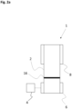
- Fig. 2a shows a schematic representation of the belt drive 1 according to the invention from Figure 1 according to a second exemplary embodiment in plan view.
- the drive pulley 6 is driven by the drive motor 4.
- the toothed belt 2 has a first marking 16, wherein as the toothed belt 2 rotates, the first marking 16 is detected successively by the first sensor element 10 and the second sensor element 12, wherein the first signal SR1 and the second signal SR2 are dependent on the detection of the first marking 16.
- the first marking 16 is arranged as a narrow strip provided with ferromagnetic particles on the back of the toothed belt 2.
- the first marking 16 runs transversely to the longitudinal direction of the toothed belt 2.
- the ferromagnetic particles are present in the form of a mixture additive in the polymer base material of the toothed belt 2.
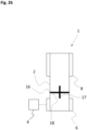
- Fig. 2b shows a schematic representation of the belt drive 1 according to the invention according to a third embodiment in plan view.
- the first marking 16 has a first marking section 17 extending in the longitudinal direction of the toothed belt 2 and a second marking section extending transversely to the longitudinal direction 18, wherein the first marking section 17 and the second marking section 18 intersect each other.
- the computing unit 14 can use a first marking 16 configured in this way to determine the position of the first marking 16 relative to the first sensor element 10 at a time of maximum intensity of the first signal SR1 and, from this, determine an entry angle ⁇ of the slack strand 5 onto the drive pulley 6.
Landscapes
- Engineering & Computer Science (AREA)
- General Engineering & Computer Science (AREA)
- Mechanical Engineering (AREA)
- Physics & Mathematics (AREA)
- General Physics & Mathematics (AREA)
- Devices For Conveying Motion By Means Of Endless Flexible Members (AREA)
Applications Claiming Priority (1)
| Application Number | Priority Date | Filing Date | Title |
|---|---|---|---|
| DE102023209656.0A DE102023209656A1 (de) | 2023-09-29 | 2023-09-29 | Verfahren und Vorrichtung zur Überwachung eines Riementriebs |
Publications (1)
| Publication Number | Publication Date |
|---|---|
| EP4530596A1 true EP4530596A1 (fr) | 2025-04-02 |
Family
ID=92883283
Family Applications (1)
| Application Number | Title | Priority Date | Filing Date |
|---|---|---|---|
| EP24201237.5A Pending EP4530596A1 (fr) | 2023-09-29 | 2024-09-19 | Procédé et dispositif de surveillance d'un entraînement à courroie |
Country Status (2)
| Country | Link |
|---|---|
| EP (1) | EP4530596A1 (fr) |
| DE (1) | DE102023209656A1 (fr) |
Citations (6)
| Publication number | Priority date | Publication date | Assignee | Title |
|---|---|---|---|---|
| EP0382115A2 (fr) | 1989-02-10 | 1990-08-16 | Gebrüder Hofmann GmbH & Co. KG Maschinenfabrik | Système de contrôle pour une transmission à courroie |
| US9228909B1 (en) | 2014-05-13 | 2016-01-05 | Google Inc. | Methods and systems for sensing tension in a timing belt |
| WO2016177883A1 (fr) | 2015-05-07 | 2016-11-10 | Walther Flender Gmbh | Entraînement par courroie et procédé permettant de surveiller ledit entraînement |
| DE102019206169A1 (de) | 2019-04-30 | 2020-11-05 | Contitech Antriebssysteme Gmbh | Verfahren zur Überwachung eines Riementriebs |
| US20210010899A1 (en) * | 2019-07-11 | 2021-01-14 | Fanuc Corporation | Power transmission device and industrial machine |
| WO2021200285A1 (fr) * | 2020-03-31 | 2021-10-07 | いすゞ自動車株式会社 | Dispositif et procédé d'estimation |
-
2023
- 2023-09-29 DE DE102023209656.0A patent/DE102023209656A1/de active Pending
-
2024
- 2024-09-19 EP EP24201237.5A patent/EP4530596A1/fr active Pending
Patent Citations (7)
| Publication number | Priority date | Publication date | Assignee | Title |
|---|---|---|---|---|
| EP0382115A2 (fr) | 1989-02-10 | 1990-08-16 | Gebrüder Hofmann GmbH & Co. KG Maschinenfabrik | Système de contrôle pour une transmission à courroie |
| US9228909B1 (en) | 2014-05-13 | 2016-01-05 | Google Inc. | Methods and systems for sensing tension in a timing belt |
| WO2016177883A1 (fr) | 2015-05-07 | 2016-11-10 | Walther Flender Gmbh | Entraînement par courroie et procédé permettant de surveiller ledit entraînement |
| DE202016008121U1 (de) | 2015-05-07 | 2017-03-09 | Walther Flender Gmbh | Riemenantrieb |
| DE102019206169A1 (de) | 2019-04-30 | 2020-11-05 | Contitech Antriebssysteme Gmbh | Verfahren zur Überwachung eines Riementriebs |
| US20210010899A1 (en) * | 2019-07-11 | 2021-01-14 | Fanuc Corporation | Power transmission device and industrial machine |
| WO2021200285A1 (fr) * | 2020-03-31 | 2021-10-07 | いすゞ自動車株式会社 | Dispositif et procédé d'estimation |
Also Published As
| Publication number | Publication date |
|---|---|
| DE102023209656A1 (de) | 2025-04-03 |
Similar Documents
| Publication | Publication Date | Title |
|---|---|---|
| EP3963303B1 (fr) | Procédé de surveillance d'un entraînement par courroie | |
| EP0725207B1 (fr) | Procédé pour la surveillance d'usure d'une chaíne de distribution pour un moteur à combustion interne et dispositif pour son exécution | |
| EP2910904B1 (fr) | Capteur à chaîne à réluctance et procédé de mesure d'étirement de chaîne | |
| EP4314756B1 (fr) | Dispositif et procédé de détermination d'une extension longitudinale et de la vitesse moyenne d'une courroie, et de détermination de la vitesse d'au moins une poulie à courroie | |
| EP2804826B1 (fr) | Surveillance de la vitesse de déplacement d'une bande de matière | |
| EP1843055B1 (fr) | Palier de roulement doté d'un capteur | |
| EP1915516B1 (fr) | Moteur a combustion interne a pistons alternatifs et procede de determination de l'usure d'un element de transmission dispose entre le vilebrequin et l'arbre a cames | |
| EP2607856A2 (fr) | Dispositif de mesure du couple, sens de rotation et vitesse de rotation de l'arbre d'un engrenage, notamment l'arbre d'entraînement d'une mécanique d'azimut d'une éolienne | |
| EP2131178A1 (fr) | Procédé de diagnostic pour au moins un roulement à billes, en particulier pour un palier à billes oblique, système de diagnostic correspondant et utilisation d'un tel système de diagnostic | |
| DE102014105678A1 (de) | Sensorpaketierung auf der abtriebsseite von vorderradantriebgetrieben | |
| DE102021121736A1 (de) | Set aus Komponenten zum Zusammenbau von steigungstreuen Planetenwälzgetrieben | |
| EP1251337A2 (fr) | Dispositif pour la détection de la direction de mouvement d'un composant mobile | |
| DE102019118008B4 (de) | Rollengewindetrieb mit AOW(Akustische Oberflächenwellen)-Sensor | |
| DE10063844A1 (de) | Antriebssystem für Rolltreppen oder Rollsteige | |
| EP4530596A1 (fr) | Procédé et dispositif de surveillance d'un entraînement à courroie | |
| DE19652785A1 (de) | Ausrückvorrichtung mit integriertem Wegsensor für eine hydraulisch betätigte Reibungskupplung | |
| EP3885597A1 (fr) | Embrayage et méthode de détection sans contact de l'usure de l'embrayage | |
| EP2786110B1 (fr) | Procédé de surveillance de l'état d'un palier guidant un moteur électrique sur un arbre | |
| DE102006055049B3 (de) | Kombinierter Lenkwinkel- und Drehmomentsensor | |
| WO2020002092A1 (fr) | Dispositif de surveillance d'usure et vis à billes | |
| DE102007039136A1 (de) | Spannrolle eines Zugmitteltriebs | |
| DE102021200478A1 (de) | Vorrichtung und Verfahren zur Ermittlung einer Längsdehnung eines Riemens | |
| EP3598096A1 (fr) | Courroie et système | |
| DE102007049977B3 (de) | Inkrementale Messeinrichtung zur Erfassung von Drehzahl, Drehrichtung und der Axialposition von axial verschieblichen Zahnrädern | |
| AT502974B1 (de) | Verfahren zur diagnose einer kette in einem antriebssystem |
Legal Events
| Date | Code | Title | Description |
|---|---|---|---|
| PUAI | Public reference made under article 153(3) epc to a published international application that has entered the european phase |
Free format text: ORIGINAL CODE: 0009012 |
|
| STAA | Information on the status of an ep patent application or granted ep patent |
Free format text: STATUS: THE APPLICATION HAS BEEN PUBLISHED |
|
| AK | Designated contracting states |
Kind code of ref document: A1 Designated state(s): AL AT BE BG CH CY CZ DE DK EE ES FI FR GB GR HR HU IE IS IT LI LT LU LV MC ME MK MT NL NO PL PT RO RS SE SI SK SM TR |
|
| STAA | Information on the status of an ep patent application or granted ep patent |
Free format text: STATUS: REQUEST FOR EXAMINATION WAS MADE |
|
| 17P | Request for examination filed |
Effective date: 20251002 |
|
| GRAP | Despatch of communication of intention to grant a patent |
Free format text: ORIGINAL CODE: EPIDOSNIGR1 |
|
| STAA | Information on the status of an ep patent application or granted ep patent |
Free format text: STATUS: GRANT OF PATENT IS INTENDED |