EP4530596A1 - Method and apparatus for monitoring a belt drive - Google Patents
Method and apparatus for monitoring a belt drive Download PDFInfo
- Publication number
- EP4530596A1 EP4530596A1 EP24201237.5A EP24201237A EP4530596A1 EP 4530596 A1 EP4530596 A1 EP 4530596A1 EP 24201237 A EP24201237 A EP 24201237A EP 4530596 A1 EP4530596 A1 EP 4530596A1
- Authority
- EP
- European Patent Office
- Prior art keywords
- belt
- drive
- sensor element
- signal
- computing unit
- Prior art date
- Legal status (The legal status is an assumption and is not a legal conclusion. Google has not performed a legal analysis and makes no representation as to the accuracy of the status listed.)
- Pending
Links
Images

Classifications
-
- G—PHYSICS
- G01—MEASURING; TESTING
- G01M—TESTING STATIC OR DYNAMIC BALANCE OF MACHINES OR STRUCTURES; TESTING OF STRUCTURES OR APPARATUS, NOT OTHERWISE PROVIDED FOR
- G01M13/00—Testing of machine parts
- G01M13/02—Gearings; Transmission mechanisms
- G01M13/023—Power-transmitting endless elements, e.g. belts or chains
-
- F—MECHANICAL ENGINEERING; LIGHTING; HEATING; WEAPONS; BLASTING
- F16—ENGINEERING ELEMENTS AND UNITS; GENERAL MEASURES FOR PRODUCING AND MAINTAINING EFFECTIVE FUNCTIONING OF MACHINES OR INSTALLATIONS; THERMAL INSULATION IN GENERAL
- F16H—GEARING
- F16H57/00—General details of gearing
- F16H57/01—Monitoring wear or stress of gearing elements, e.g. for triggering maintenance
Definitions
- the invention relates to a method and a device for monitoring a belt drive with at least one drive pulley driven by a drive motor and at least one driven pulley and at least one drive belt, preferably a toothed belt, wherein the drive belt wraps around the drive pulley and driven pulley circumferentially over a partial circumference in each case, and at least one first sensor element assigned to the drive belt.
- Various types of drive belts are known, including toothed belts, flat belts, V-belts and V-ribbed belts.
- condition monitoring of drive belts required during operation can usually only be carried out by visual inspection and mechanical tests.
- encapsulated belt drives i.e. belt drives that are enclosed in a dust and waterproof housing
- a permanent visual inspection is not possible or only possible with great effort for design reasons.
- Encapsulated belt drives are particularly common in vehicle steering gears, as these gears are located in areas exposed to heavy contamination. Steering belt drives are often designed for a lifetime, making periodic inspection unnecessary. However, such a design maxim quickly leads to over-dimensioning of all components, which in turn can increase weight and thus energy consumption.
- the detection of pretension losses is a key assessment criterion for the condition of the belt.
- Settling or elongation of the timing belt during operation can reduce the static pretension of the belt.
- dynamic load effects can lead to a temporary reduction in the pretension in the slack side, i.e. the section of the belt that does not contribute to power transmission.
- the entry angle of the slack side on the pulley increases. In other words, the angle of contact of the belt on the pulley decreases, which means that fewer teeth of the belt are in engagement with the pulley and the specific load per belt tooth increases.
- the timing belt in a steering system is a safety-relevant component, which is why it is particularly important to detect an impending belt failure in a timely manner.
- the EP 0 382 115 A2 relates to a monitoring device for a belt drive for the early detection of material fatigue in a drive belt.
- the drive belt has markings equally spaced apart in its longitudinal direction, wherein the markings can be scanned by two spaced-apart scanning devices.
- the scanning signals are temporally related to one another in a signal evaluation device connected to the scanning devices, depending on the distance between the two scanning devices and the running speed of the drive belt.
- the US 9 228 909 B1 discloses a system for measuring force in a belt drive.
- the belt has spaced-apart markers whose spacing changes as a result of a changing force. By detecting the running time of two marker elements, a correlation can be established with the force in the belt drive or with the torque transmitted by the belt.
- the DE 20 2016 008 121 U1 discloses a belt drive consisting of a pulley, a belt, and a monitoring device.
- a marker is attached to the belt and the pulley.
- a signal is triggered when the markers on the belt and the drive pulley are aligned.
- the markers for position identification can be based on various sensor technologies, e.g., optical, inductive, capacitive, or magnetic effects.
- the DE 10 2019 206 169 A1 discloses a method for monitoring a belt drive, wherein the belt and the rotor of the drive motor have a marking that can be monitored via a sensor element. By comparing a temporal and spatial correlation of the sensor signals of the belt and the rotor with a reference value determined in the new condition, conclusions can be drawn about a tooth jump of the belt in the pulley.
- the object of the invention is to provide a method for monitoring a belt drive and a device designed for this purpose, wherein a change in the pretension force can be detected at an early stage. Additionally or alternatively, the object is to provide a solution for detecting a tooth jump of a timing belt on a pulley, whereby the number of sensors required to detect tooth overlap can be reduced.
- a further solution to the problem is provided by a device for monitoring a belt drive having the features of independent claim 8, as well as by a belt drive according to claim 15.
- the present invention relates to a method for monitoring a belt drive having at least one drive pulley driven by a drive motor, at least one driven pulley, and at least one drive belt.
- the drive belt is preferably designed as a toothed belt.
- the drive belt comprises a polymeric base material, and the drive belt wraps around the drive pulley and driven pulley circumferentially over a partial circumference.
- a first sensor element is assigned to the drive belt.
- a reference value for the distance between the first sensor element and the drive belt in the original state is stored in the computing unit.
- the computing unit can determine the distance between the first sensor element and the drive belt.
- the first sensor element is designed to detect a changing air gap between the first sensor element and a surface of the drive belt.
- the first sensor element can be designed, for example, as an optical, capacitive, inductive, or magnetic field sensor.
- the first sensor element can preferably be arranged in a region in which the drive belt runs onto or off the drive pulley.
- a warning or alarm signal can be issued. This can indicate a critical loss of pretension force, allowing the belt to be replaced or retensioned in a timely manner.
- an event can be counted incrementally.
- This event can represent a tooth jump, where the drive belt briefly lifts itself off one of the pulleys, preferably the drive pulley, and jumps into the next tooth gap.
- a further tolerance value can be specified to detect this event. Since only a certain number of tooth jumps are permissible for a timing belt, counting the tooth jumps can be used to predict the remaining service life or the remaining number of permissible tooth jumps until the timing belt needs to be replaced.
- the computing unit determines a change in the pretensioning force of a belt strand, preferably the slack strand, from a change in the distance between the first sensor element and the drive belt.
- the change in distance can be used to infer an absolute change in the pretension force of a belt strand.
- an additional calibration curve can be stored in the computing unit, which, based on a reference value of the pretension force in the static state, allows the change in distance between the first sensor element and the drive belt to be correlated with a change in the pretension force.
- the warning or alarm signal can be issued when a specified critical preload force is undershot.
- the drive belt has at least one first marking, wherein the passage of the first marking is detected by the first sensor element and/or the second sensor element during belt rotation.
- the first signal and/or the second signal are dependent on the detection of the first marking.
- the marking can be formed as a narrow strip on the drive belt, preferably on the back of the belt, provided with ferromagnetic or electrically conductive particles.
- the marking is a strip formed transversely to the longitudinal direction of the drive belt, which forms a clear and locally narrowly limited signal when passing the first and/or second sensor element.
- the ferromagnetic or electrically conductive Particles can be present in the form of a blend additive in the polymer base material of the drive belt.
- the first marking comprises a first marking portion extending in the longitudinal direction of the drive belt and a second marking portion extending transversely to the longitudinal direction, wherein the first marking portion and the second marking portion intersect each other.
- the computing unit determines the position of the first marking relative to the first sensor element or the second sensor element at a time of maximum intensity of the first signal and/or the second signal and from this an entry angle of a belt strand, preferably the slack strand.
- the first sensor element and/or the second sensor element have a plurality of sensors oriented in different spatial directions.
- the intersecting arrangement of the marking sections in the longitudinal and transverse directions not only allows for the distance between the sensor element and the drive belt, but also for the determination of the entry angle of the slack side of the drive belt onto the pulley.
- This advantageously increases the accuracy of determining the pretension force loss.
- wear-related influences of the markings which lead to a change in the intensity of the sensor signals even with the same distance between the belt and the sensor element, can be advantageously avoided, resulting in erroneous measurement results.
- the speeds of the drive pulley and the drive belt are determined independently of each other and compared. With a timing belt, the speeds are identical due to the positive connection between the belt and pulley. If the speeds of the belt and pulley deviate from a tolerance range stored in the computing unit, a warning is given as a tooth jump in the drive belt according to process step I).
- the invention also relates to the use of the method according to the invention for monitoring a belt drive with at least one
- the drive belt is preferably designed as a toothed belt.
- the belt drive is preferably part of a transmission in an electromechanical power steering system of a motor vehicle.
- Steer-by-wire systems in particular, in which there is no mechanical connection between the steering wheel and the steering gear, must meet particularly high safety requirements, which is why the use of a belt drive with the monitoring device according to the invention is particularly advantageous for this purpose.
- Steer-by-wire systems are preferably used in autonomous vehicles.
- the belt drive according to the invention can be used in a wide variety of applications, for example in braking systems with an electromechanical brake booster or in chassis systems with an active electromechanical adjustment device.
- the present invention also relates to a device for monitoring a belt drive with at least one drive pulley and one driven pulley driven by an electric drive motor and at least one drive belt, preferably a toothed belt with a polymer base material, wherein the drive belt wraps around the drive pulley and the driven pulley circumferentially over a partial circumference.
- At least one first sensor element is assigned to the drive belt, wherein the first sensor element is designed to detect a first signal.
- the computing unit is designed to output a warning or alarm signal and/or to incrementally count an event when a specified tolerance value is undershot.
- the first signal can be forwarded to the computing unit to determine the distance between the first sensor element and the drive belt.
- the drive belt serves as a power transmission element between a motor and one or more output shafts.
- the belt drive can also be operated reversibly, i.e., in both directions of rotation.
- a reference value for the distance between the first sensor element and the drive belt in the original state is stored in the computing unit stored.
- the computing unit can determine the distance between the first sensor element and the drive belt.
- the first sensor element is designed to detect a changing air gap between the first sensor element and a surface of the drive belt.
- the first sensor element can be designed, for example, as an optical, capacitive, inductive, or magnetic field sensor.
- the first sensor element can preferably be arranged in a region where the drive belt runs onto or off the drive pulley.
- a warning or alarm signal can be issued. This can indicate a critical loss of pretension force, allowing the belt to be replaced or retensioned in a timely manner.
- an event can be counted incrementally.
- This event can represent a tooth jump, where the drive belt briefly lifts itself off one of the pulleys, preferably the drive pulley, and jumps into the next tooth gap.
- a further tolerance value can be specified to detect this event. Since only a certain number of tooth jumps are permissible for a timing belt, counting the tooth jumps can be used to predict the remaining service life or the remaining number of permissible tooth jumps until the timing belt needs to be replaced.
- the computing unit is designed to determine a change in the pretensioning force of a belt strand, preferably the slack strand, from a change in the distance between the first sensor element and the drive belt.
- the change in distance can be used to infer an absolute change in the pretension force of a belt strand.
- an additional calibration curve can be stored in the computing unit, which, based on a reference value of the pretension force in the static state, allows the change in distance between the first sensor element and the drive belt to be correlated with a change in the pretension force.
- the warning or alarm signal can be issued when a specified critical preload force is exceeded.
- the belt drive has a second sensor element associated with the drive belt, wherein the second sensor element is configured to detect a second signal.
- the second signal can be forwarded to the computing unit for determining a distance between the second sensor element and the drive belt, wherein the computing unit is configured to output a warning or alarm signal and/or to incrementally count an event if a specified tolerance value is undershot.
- the second sensor element can be identical to the first sensor element and arranged in an area opposite the first sensor element, in which the drive belt runs onto or off the drive pulley.
- the second sensor element can monitor each belt strand individually and independently of one another, enabling monitoring of the belt drive in both directions of rotation.
- the drive belt has at least one first marking, wherein the passage of the first marking through the first sensor element and/or the second sensor element is detectable during the belt rotation, wherein the first signal and/or the second signal is dependent on the detection of the first marking.
- the marking can be a narrow stripe with ferromagnetic or electrically conductive particles on the drive belt, preferably on the belt back.
- the marking is a stripe formed transversely to the longitudinal direction of the drive belt, which generates a distinct and locally limited signal when passing the sensor element.
- the ferromagnetic or electrically conductive particles can be present in the form of a mixture additive in the polymer base material of the drive belt.
- the first marking comprises a first marking portion extending in the longitudinal direction of the drive belt and a second marking portion extending transversely to the longitudinal direction, wherein the first marking portion and the second marking portion intersect each other.
- the first sensor element and/or the second sensor element has a plurality of sensors oriented in different spatial directions, wherein the computing unit is designed to determine the position of the first marking relative to the first sensor element or the second sensor element at a time of maximum intensity of the first signal and/or the second signal and to determine therefrom an entry angle of a belt strand, preferably the slack strand.
- the intersecting arrangement of the markings in the longitudinal and transverse directions not only allows for the distance between the sensor element and the drive belt, but also for the determination of the entry angle of the slack side of the drive belt onto the pulley. This advantageously increases the accuracy of determining the pretension force loss. By determining the entry angle, wear-related influences of the markings, which lead to a change in the intensity of the sensor signals even with the same distance between the belt and the sensor element, can be avoided.
- the first marking may comprise ferromagnetic or electrically conductive particles.
- the ferromagnetic or electrically conductive particles may preferably be mixed into the polymeric base material of the drive belt.
- the drive belt may have a strip of polymeric material containing the ferromagnetic or electrically conductive particles, preferably on the back side, i.e., the side of the drive belt opposite the force-transmitting side and preferably the side containing the teeth of the toothed belt.
- the computing unit is designed to determine the circumferential speed of the drive pulley from a speed signal of the drive motor or the drive pulley and a diameter of the drive pulley.
- the computing unit is designed to determine a time interval between a first time of detection of the first sensor signal and a second time of detection of the second sensor signal, wherein the computing unit is designed to determine the speed of the drive belt from the distance traveled by the drive belt over the section length between the sensor element and the second sensor element during the time interval and to compare it with the circumferential speed of the drive pulley.
- the computing unit is designed to output a warning or alarm signal in the event of a deviation from a tolerance range between the circumferential speed of the drive pulley and the speed of the drive belt.
- the speeds of the drive pulley and the drive belt are determined independently of each other and compared.
- the speeds are essentially identical due to the positive connection between the belt and pulley. If the speeds of the belt and pulley deviate from each other outside a tolerance range stored in the processing unit, the processing unit can indicate a tooth jump in the drive belt.
- the present invention also relates to a belt drive with a device according to the invention for monitoring a belt drive.
- the aforementioned properties and advantages can be applied to any belt drive.
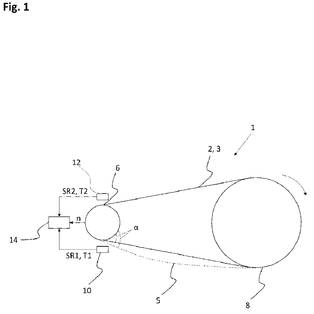
- the belt drive 1 shown has a drive belt 2 designed as a toothed belt 2.
- the toothed belt 2 wraps around a drive pulley 6 and a driven pulley 8.
- the drive pulley 6 and the driven pulley 8 have teeth on their outer circumference, which engage positively with the teeth of the toothed belt 2 in the area of the wrap of the toothed belt 2.
- the drive pulley 6 and the driven pulley 8 have different diameters, so that the belt drive 1 is designed as a transmission gear.
- the belt strands of the toothed belt 2 are arranged between the drive pulley 6 and the driven pulley 8. In the static state, i.e. without power transmission of the belt, the pretension force in both belt strands is the same.
- the tensile force in the load side 3 increases, while the force in the slack side 5 decreases.
- the dynamic application is shown by the dashed line in the slack side 5.
- the toothed belt 2 sags in the area of the slack side 5, so that the entry angle ⁇ of the slack side 5 onto the drive pulley 6 increases.
- the entry angle ⁇ increases, the number of teeth of the toothed belt 2 that engage with the drive pulley 6 decreases.
- the load side 3 and the slack side 5 are arranged in the belt drive 1 shown in the direction of the arrow according to the direction of rotation. In reversing operation, i.e. with a different direction of rotation, the load side 3 and the slack side 5 would alternate.
- the illustrated belt drive 1 has a monitoring device, wherein a first sensor element 10 for detecting a first signal SR1 and a second sensor element 12 for detecting a second signal SR2 are assigned to the toothed belt 2.
- the first sensor element 10 and the second sensor element 12 are spaced apart from the toothed belt 2 and arranged without contact.
- the first sensor element 10 is arranged in the area where the slack side 5 runs into the drive pulley 6.
- the second sensor element 12 is arranged opposite the first sensor element 10 in the area where the tight side 2 runs out of the drive pulley 6.
- the first signal SR1 and/or the second signal SR2 are forwarded to a computing unit 14 for signal evaluation.
- a reference value for the distance between the first sensor element 10 and the toothed belt 2 and the second sensor element 12 and the toothed belt 2 in the static original state is stored in the computing unit 14.
- the computing unit 14 can Distance between the first sensor element 10 and the toothed belt 2 and the second sensor element 12 and the toothed belt 2 can be determined.
- the first sensor element 10 and the second sensor element 12 are configured to detect a changing air gap between the first sensor element 10 and a surface of the toothed belt 2 and the second sensor element 12 and the surface of the toothed belt 2.
- the first sensor element 10 and the second sensor element 12 are configured as magnetic field sensors.
- the computing unit 14 issues a warning or alarm signal.
- the computing unit 14 can determine a change in the pretension force of the slack side 5.
- a further calibration curve is stored in the computing unit 14 which, based on a reference value of the pretension force in the static state, enables the change in distance between the first sensor element 10 and the toothed belt 2 to be assigned to a change in the pretension force.
- the warning or alarm signal is issued when a specified critical pretension force is undershot.
- the computing unit 14 incrementally counts an event when the distance between the second sensor element 12 and the toothed belt 2 falls below a possibly further specified distance.
- This event represents a tooth jump, whereby the toothed belt 2 briefly lifts itself from the drive pulley 6 and jumps into the next tooth gap. Since only a certain number of tooth jumps is permissible for the toothed belt 2, the remaining service life or the remaining number of permissible tooth jumps until the toothed belt 2 needs to be replaced can be predicted by counting the tooth jumps.
- the computing unit 14 can determine the circumferential speed of the drive pulley 6 from a speed signal n of a drive motor 4 or the drive pulley 6 and a diameter of the drive pulley 6.
- the computing unit 14 determines a time interval between a first time T1 of detecting the first sensor signal SR1 and a second time T2 of detecting the second sensor signal SR2, wherein the computing unit 14 determines the speed of the toothed belt 2 from the distance traveled by the toothed belt 2 over the section length between the first sensor element 10 and the second sensor element 12 during the time interval and compares it with the circumferential speed of the drive pulley 6. If the speeds of the toothed belt 2 and the drive pulley 6 deviate from one another outside a tolerance range stored in the computing unit 14, the computing unit 14 indicates a tooth jump of the toothed belt 2.
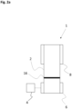
- Fig. 2a shows a schematic representation of the belt drive 1 according to the invention from Figure 1 according to a second exemplary embodiment in plan view.
- the drive pulley 6 is driven by the drive motor 4.
- the toothed belt 2 has a first marking 16, wherein as the toothed belt 2 rotates, the first marking 16 is detected successively by the first sensor element 10 and the second sensor element 12, wherein the first signal SR1 and the second signal SR2 are dependent on the detection of the first marking 16.
- the first marking 16 is arranged as a narrow strip provided with ferromagnetic particles on the back of the toothed belt 2.
- the first marking 16 runs transversely to the longitudinal direction of the toothed belt 2.
- the ferromagnetic particles are present in the form of a mixture additive in the polymer base material of the toothed belt 2.
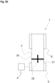
- Fig. 2b shows a schematic representation of the belt drive 1 according to the invention according to a third embodiment in plan view.
- the first marking 16 has a first marking section 17 extending in the longitudinal direction of the toothed belt 2 and a second marking section extending transversely to the longitudinal direction 18, wherein the first marking section 17 and the second marking section 18 intersect each other.
- the computing unit 14 can use a first marking 16 configured in this way to determine the position of the first marking 16 relative to the first sensor element 10 at a time of maximum intensity of the first signal SR1 and, from this, determine an entry angle ⁇ of the slack strand 5 onto the drive pulley 6.
Landscapes
- Engineering & Computer Science (AREA)
- General Engineering & Computer Science (AREA)
- Mechanical Engineering (AREA)
- Physics & Mathematics (AREA)
- General Physics & Mathematics (AREA)
- Devices For Conveying Motion By Means Of Endless Flexible Members (AREA)
Abstract
Die Erfindung betrifft ein Verfahren zur Überwachung eines Riementriebs (1) mit mindestens einer durch einen Antriebsmotor (4) angetriebenen Antriebsscheibe (6) und mindestens einer Abtriebsscheibe (8) und mindestens einem Antriebsriemen (2), vorzugsweise einem Zahnriemen (2), wobei der Antriebsriemen (2) die Antriebsscheibe (6) und Abtriebsscheibe (8) umlaufend über jeweils einen Teilumfang umschlingt, und mindestens einem dem Antriebsriemen (2) zugeordneten ersten Sensorelement (10), gekennzeichnet durch die folgenden Verfahrensschritte:
a) Erfassen eines ersten Signals (SR1) durch das erste Sensorelement (10),
b) Übertragung des ersten Signals (SR1) an eine Recheneinheit (14),
c) Ausgabe eines Warn- oder Alarmsignals und/oder Inkrementelles Zählen eines Ereignisses bei Unterschreiten eines festgelegten Toleranzwertes durch die Recheneinheit (14).
a) detecting a first signal (SR1) by the first sensor element (10),
b) transmission of the first signal (SR1) to a computing unit (14),
c) Output of a warning or alarm signal and/or incremental counting of an event when a specified tolerance value is undershot by the computing unit (14).
Description
Die Erfindung betrifft ein Verfahren und eine Vorrichtung zur Überwachung eines Riementriebs mit mindestens einer durch einen Antriebsmotor angetriebenen Antriebsscheibe und mindestens einer Abtriebsscheibe und mindestens einem Antriebsriemen, vorzugsweise einem Zahnriemen, wobei der Antriebsriemen die Antriebsscheibe und Abtriebsscheibe umlaufend über jeweils einen Teilumfang umschlingt, und mindestens einem dem Antriebsriemen zugeordneten ersten Sensorelement.The invention relates to a method and a device for monitoring a belt drive with at least one drive pulley driven by a drive motor and at least one driven pulley and at least one drive belt, preferably a toothed belt, wherein the drive belt wraps around the drive pulley and driven pulley circumferentially over a partial circumference in each case, and at least one first sensor element assigned to the drive belt.
Riementriebe zur Übertragung von Drehmomenten und Drehbewegungen sind auf vielen technischen Gebieten bekannt und gelten als leicht bauende, geräuscharme und hohe Drehmomente übertragende Antriebssysteme. Dabei umschlingt der Antriebsriemen über einen Teilumfang bzw. über einen Umschlingungswinkel jeweils eine Antriebsscheibe oder -rolle und mindestens eine Abtriebsscheibe oder -rolle und überträgt dort die Kräfte durch Reibung und/oder durch Formschluss. Dies kann der Übertragung einer fortlaufenden Bewegung dienen, um z.B. die Rotation der Antriebseinheit mit einem Verbrennungsmotor, mit einem Hybridmotor oder mit einem Elektromotor eines Fahrzeugs auf die Räder des Fahrzeugs zu übertragen. Es können jedoch auch Änderungen der Stellung der Abtriebseinheit auf diese Art und Weise vorgenommen werden, um z.B. eine Lenkbewegung eines Lenkrads eines elektromechanischen Lenksystems eines Fahrzeugs auf dessen Räder zu übertragen.Belt drives for transmitting torque and rotary motion are well known in many technical fields and are considered lightweight, low-noise, and high-torque drive systems. The drive belt wraps around a drive pulley or roller and at least one driven pulley or roller over a partial circumference or across a certain angle of wrap, transmitting forces there through friction and/or positive engagement. This can be used to transmit continuous motion, for example, to transfer the rotation of the drive unit of a combustion engine, a hybrid engine, or an electric motor of a vehicle to the vehicle's wheels. However, changes to the position of the output unit can also be made in this way, for example to transfer a steering movement of a steering wheel of an electromechanical steering system of a vehicle to its wheels.
Als Antriebsriemen sind verschiedene Ausführungsformen von Zahnriemen, Flachriemen, Keilriemen oder Keilrippenriemen bekannt.Various types of drive belts are known, including toothed belts, flat belts, V-belts and V-ribbed belts.
Eine während der Betriebszeit erforderliche Zustandsüberwachung an Antriebsriemen ist in der Regel nur durch visuelle Inspektion und mechanische Prüfungen realisierbar. Bei gekapselten Riementrieben, d.h. bei Riementrieben, die in einem Staub und wasserdichten Gehäuse eingeschlossen sind, ist eine permanente visuelle Inspektion aus konstruktionsbedingten Gründen nicht oder nur unter großem Aufwand möglich.The condition monitoring of drive belts required during operation can usually only be carried out by visual inspection and mechanical tests. In the case of encapsulated belt drives, i.e. belt drives that are enclosed in a dust and waterproof housing, a permanent visual inspection is not possible or only possible with great effort for design reasons.
Gekapselte Riementriebe findet man insbesondere bei Lenkungsgetrieben für Fahrzeuge, da diese Getriebe in einem Bereich angeordnet sind, welcher starken Verschmutzungen ausgesetzt ist. So sind Lenkungsriemengetriebe bisher oft auf eine Lebensdauer ausgelegt, was eine zwischenzeitliche Inspektion nicht unbedingt erforderlich macht. Durch eine solche Auslegungsmaxime gerät die Konstruktion jedoch schnell in eine Überdimensionierung aller Bauteile, was wiederum das Gewicht damit den Energieverbrauch erhöhen kann.Encapsulated belt drives are particularly common in vehicle steering gears, as these gears are located in areas exposed to heavy contamination. Steering belt drives are often designed for a lifetime, making periodic inspection unnecessary. However, such a design maxim quickly leads to over-dimensioning of all components, which in turn can increase weight and thus energy consumption.
Bei Zahnriementrieben ist die Detektion der Vorspannungsverluste ein wesentliches Beurteilungskriterium für den Zustand des Riemens. Durch Setzungserscheinungen bzw. eine Längung des Zahnriemens während der Betriebsdauer kann sich die statische Vorspannkraft des Riemens verringern. Zusätzlich können dynamische Lasteinwirkungen zu einer zeitweisen Verringerung der Vorspannkraft in dem Leertrum, d.h. dem Riemenabschnitt, der nicht zur Leistungsübertragung beiträgt, führen. Mit sinkender Vorspannkraft des Leertrums vergrößert sich der Einlaufwinkel des Leertrums auf die Riemenscheibe. Mit anderen Worten verringert sich der Umschlingungswinkel des Riemens an der Riemenscheibe, wodurch weniger Zähne des Riemens mit der Riemenscheibe im Eingriff stehen und die spezifische Belastung je Riemenzahn steigt. Wenn die Vorspannkraft im Leertrum des Riemens ein kritisches Minimum erreicht, kann dies dazu führen, dass die im Eingriff mit der Riemenscheibe verbleibenden Zähne des Zahnriemens der Belastung nicht mehr standhalten und sich infolgedessen verformen oder sogar abscheren. Der Zahnriemen kann hierbei in der Riemenscheibe überspringen. Der Zahnübersprung deutet auf einen späteren Ausfall des Riementriebs hin, weshalb die frühzeitige Detektion für die Funktionssicherheit unbedingt relevant ist. Bei einem solchen Zahnübersprung dreht die Antriebsriemenscheibe bei Überlastung unterhalb des Riemens durch, der Zahn des Riemens kann auf der Riemenscheibe mehrfach überspringen, sodass der Zahnbereich des Riemens verschleißt.In timing belt drives, the detection of pretension losses is a key assessment criterion for the condition of the belt. Settling or elongation of the timing belt during operation can reduce the static pretension of the belt. In addition, dynamic load effects can lead to a temporary reduction in the pretension in the slack side, i.e. the section of the belt that does not contribute to power transmission. As the pretension on the slack side decreases, the entry angle of the slack side on the pulley increases. In other words, the angle of contact of the belt on the pulley decreases, which means that fewer teeth of the belt are in engagement with the pulley and the specific load per belt tooth increases. If the pretension in the slack side of the belt reaches a critical minimum, this can lead to the timing belt teeth that remain in engagement with the pulley no longer being able to withstand the load and consequently deforming or even shearing off. The timing belt can then jump in the pulley. Tooth jump indicates a future failure of the belt drive, which is why early detection is crucial for functional reliability. When tooth jump occurs, the drive pulley spins under overload below the belt. The belt tooth can jump multiple times on the pulley, causing wear on the belt tooth area.
Für autonom fahrende Fahrzeuge ist der Zahnriemen in einem Lenksystem ein sicherheitsrelevantes Bauteil, weshalb es von besonderer Bedeutung ist, einen bevorstehenden Ausfall des Riemens rechtzeitig zu erkennen.For autonomous vehicles, the timing belt in a steering system is a safety-relevant component, which is why it is particularly important to detect an impending belt failure in a timely manner.
Die
Die
Die Überwachung einer relativen Positionsveränderung des Riemens in Folge eines Zahnübersprungs zu einer historischen Referenzposition wird durch den zuvor beschriebenen Stand der Technik nicht ermöglicht.The monitoring of a relative position change of the belt as a result of a tooth jump to a historical reference position is not possible with the previously described state of the art.
Die
Mithilfe der dort beschriebenen Überwachung können unter anderem bei Zahn- oder Synchronriemen Übersprünge erfasst werden, die einen sofortigenWith the help of the monitoring described there, jumps in toothed or synchronous belts can be detected, which require immediate
Wartungseingriff erforderlich machen. Ebenso kann Schlupf erkannt werden. Auch lassen sich mit der dort beschriebenen Einrichtung unter Berücksichtigung weiterer Riemenparameter exakte Aussagen über Belastungen machen, denen der Riemen über einen jeweils zurückliegenden Zeitraum ausgesetzt war.Maintenance intervention may be necessary. Slippage can also be detected. The system described there also allows precise statements to be made about the loads to which the belt was exposed over a given period of time, taking other belt parameters into account.
Auch die zu derselben Patentfamilie gehörige
Allerdings weisen die hier beschriebenen Systeme und Verfahren den Nachteil auf, dass eine genaue Positionierung des Riemens in Bezug auf die Scheiben erfolgen muss, dass insbesondere nach Reparaturen, etwa nach dem Anbringen von Ersatzscheiben oder Ersatzriemen schwierig ist.However, the systems and methods described here have the disadvantage that precise positioning of the belt in relation to the pulleys must be carried out, which is particularly difficult after repairs, for example after fitting replacement pulleys or belts.
Die
Nachteiliger Weise kann durch das Verfahren der
Für die Erfindung liegt die Aufgabe in der Bereitstellung eines Verfahrens zur Überwachung eines Riementriebs und einer dazu ausgebildeten Vorrichtung, wobei eine Veränderung der Vorspannungskraft bereits frühzeitig detektierbar ist. Zusätzlich oder alternativ liegt die Aufgabe in der Bereitstellung einer Lösung zur Detektion eines Zahnübersprungs eines Zahnriemens an einer Riemenscheibe, wobei die Anzahl der zur Detektion des Zahnübersprungs erforderlichen Sensoren verringert werden kann.The object of the invention is to provide a method for monitoring a belt drive and a device designed for this purpose, wherein a change in the pretension force can be detected at an early stage. Additionally or alternatively, the object is to provide a solution for detecting a tooth jump of a timing belt on a pulley, whereby the number of sensors required to detect tooth overlap can be reduced.
Die Lösung dieser Aufgabe ergibt sich durch ein Verfahren zur Überwachung eines Riementriebs mit den Merkmalen des unabhängigen Anspruchs 1.This problem is solved by a method for monitoring a belt drive having the features of
Eine weitere Lösung der Aufgabe ergibt sich durch eine Vorrichtung zur Überwachung eines Riementriebs mit den Merkmalen des unabhängigen Anspruchs 8, sowie durch einen Riementrieb nach Anspruch 15.A further solution to the problem is provided by a device for monitoring a belt drive having the features of
Weitere vorteilhafte Ausbildungen sind den abhängigen Ansprüchen, der allgemeinen Beschreibung sowie den Ausführungsbeispielen zu entnehmen.Further advantageous embodiments can be found in the dependent claims, the general description and the embodiments.
Die vorliegende Erfindung betrifft ein Verfahren zur Überwachung eines Riementriebs mit mindestens einer durch einen Antriebsmotor angetriebenen Antriebsscheibe und mindestens einer Abtriebsscheibe und mindestens einem Antriebsriemen. Vorzugsweise ist der Antriebsriemen als ein Zahnriemen ausgebildet. Der Antriebsriemen weist ein polymeres Grundmaterial auf, wobei der Antriebsriemen die Antriebsscheibe und Abtriebsscheibe umlaufend über jeweils einen Teilumfang umschlingt. Dem Antriebsriemen ist ein erstes Sensorelement zugeordnet.The present invention relates to a method for monitoring a belt drive having at least one drive pulley driven by a drive motor, at least one driven pulley, and at least one drive belt. The drive belt is preferably designed as a toothed belt. The drive belt comprises a polymeric base material, and the drive belt wraps around the drive pulley and driven pulley circumferentially over a partial circumference. A first sensor element is assigned to the drive belt.
Das Verfahren ist gekennzeichnet durch die folgenden Verfahrensschritte:
- a) Erfassen eines ersten Signals durch das erste Sensorelement,
- b) Übertragung des ersten Signals an eine Recheneinheit,
- c) Ausgabe eines Warn- oder Alarmsignals und bzw. oder Inkrementelles Zählen eines Ereignisses bei Unterschreiten eines festgelegten Toleranzwertes durch die Recheneinheit.
- a) detecting a first signal by the first sensor element,
- b) Transmission of the first signal to a computing unit,
- c) Output of a warning or alarm signal and/or incremental counting of an event when a specified tolerance value is undershot by the computing unit.
Vorzugsweise ist in der Recheneinheit ein Referenzwert für den Abstand zwischen dem ersten Sensorelement und dem Antriebsriemen im Ursprungszustand hinterlegt. Über eine Kalibrierkurve, in der eine Zuordnung des Pegels des ersten Signals zu einer absoluten Abstandsveränderung zwischen dem ersten Sensorelement und dem Antriebsriemen beschrieben ist, kann durch die Recheneinheit der Abstand zwischen dem ersten Sensorelement und dem Antriebsriemen bestimmt werden.Preferably, a reference value for the distance between the first sensor element and the drive belt in the original state is stored in the computing unit. Using a calibration curve that describes the correlation between the level of the first signal and an absolute change in the distance between the first sensor element and the drive belt, the computing unit can determine the distance between the first sensor element and the drive belt.
Das erste Sensorelement ist mit anderen Worten dazu ausgebildet, einen sich verändernden Luftspalt zwischen dem ersten Sensorelement und einer Oberfläche des Antriebsriemens zu detektieren. Das erste Sensorelement kann beispielsweise als optischer, kapazitiver, induktiver oder als ein Magnetfeld-Sensor ausgebildet sein. Das erste Sensorelement kann vorzugsweise in einem Bereich angeordnet sein, in dem der Antriebsriemen auf die Antriebsscheibe aufläuft oder abläuft.In other words, the first sensor element is designed to detect a changing air gap between the first sensor element and a surface of the drive belt. The first sensor element can be designed, for example, as an optical, capacitive, inductive, or magnetic field sensor. The first sensor element can preferably be arranged in a region in which the drive belt runs onto or off the drive pulley.
Bei Unterschreiten eines festgelegten Toleranzwertes kann ein Warn- oder Alarmsignal ausgegeben werden. Hierdurch kann auf einen kritischen Vorspannungskraftverlust hingewiesen werden, sodass rechtzeitig ein Austausch oder ein Nachspannen des Riemens erfolgen kann.If a specified tolerance value is exceeded, a warning or alarm signal can be issued. This can indicate a critical loss of pretension force, allowing the belt to be replaced or retensioned in a timely manner.
Zusätzlich oder alternativ kann ein Ereignis inkrementell gezählt werden. Das Ereignis kann einen Zahnübersprung repräsentieren, wobei sich der Antriebsriemen kurzzeitig aus einer der Riemenscheiben, vorzugsweise der Antriebsriemenscheibe heraushebt und in die nächste Zahnlücke überspringt. Zur Detektion dieses Ereignisses kann ein weiterer Toleranzwert festgelegt werden. Da für einen Zahnriemen nur eine bestimmte Anzahl an Zahnübersprüngen zulässig ist, kann durch das Zählen der Zahnübersprünge die verbleibende Lebensdauer bzw. die verbleibende Anzahl zulässiger Zahnübersprünge bis zum Austausch des Zahnriemens vorhergesagt werden.Additionally or alternatively, an event can be counted incrementally. This event can represent a tooth jump, where the drive belt briefly lifts itself off one of the pulleys, preferably the drive pulley, and jumps into the next tooth gap. A further tolerance value can be specified to detect this event. Since only a certain number of tooth jumps are permissible for a timing belt, counting the tooth jumps can be used to predict the remaining service life or the remaining number of permissible tooth jumps until the timing belt needs to be replaced.
Gemäß einem weiteren Aspekt der vorliegenden Erfindung bestimmt die Recheneinheit aus einer Veränderung des Abstands zwischen dem ersten Sensorelement und dem Antriebsriemen eine Veränderung der Vorspannkraft eines Riementrums, vorzugsweise des Leertrums.According to a further aspect of the present invention, the computing unit determines a change in the pretensioning force of a belt strand, preferably the slack strand, from a change in the distance between the first sensor element and the drive belt.
Mit anderen Worten kann über die Abstandsveränderung Rückschluss auf eine absolute Veränderung der Vorspannkraft eines Riementrums gezogen werden. Hierfür kann in der Recheneinheit eine weitere Kalibrierkurve hinterlegt sein, die basierend auf einem Referenzwert der Vorspannkraft im statischen Zustand eine Zuordnung der Abstandsveränderung zwischen dem ersten Sensorelement und dem Antriebsriemen zu einer Veränderung der Vorspannkraft ermöglicht.In other words, the change in distance can be used to infer an absolute change in the pretension force of a belt strand. For this purpose, an additional calibration curve can be stored in the computing unit, which, based on a reference value of the pretension force in the static state, allows the change in distance between the first sensor element and the drive belt to be correlated with a change in the pretension force.
Gemäß Verfahrensschritt c) kann das Warn- oder Alarmsignals nach Unterschreiten einer festgelegten kritischen Vorspannungskraft ausgegeben werden.According to process step c), the warning or alarm signal can be issued when a specified critical preload force is undershot.
In einer weiteren vorteilhaften Ausbildung weist das Verfahren die folgenden weiteren Verfahrensschritte auf:
- d) Erfassen eines dem Riemen zugeordneten zweiten Signals durch ein zweites Sensorelement,
- e) Übertragen des zweiten Signals an die Recheneinheit,
- f) Ausgabe eines Warn- oder Alarmsignals und bzw. oder Inkrementelles Zählen eines Ereignisses bei Unterschreiten eines festgelegten Toleranzwertes durch die Recheneinheit.
- d) detecting a second signal associated with the belt by a second sensor element,
- e) transmitting the second signal to the computing unit,
- f) Output of a warning or alarm signal and/or incremental counting of an event when a specified tolerance value is undershot by the computing unit.
Die Verfahrensschritte d), e) und f) mit Bezug auf das zweite Sensorelement entsprechen den Verfahrensschritten a), b) und c). Das zweite Sensorelement kann identisch mit dem ersten Sensorelement ausgebildet sein und in einem dem ersten Sensorelement gegenüberliegendem Bereich angeordnet sein, in dem der Antriebsriemen auf die Antriebsscheibe aufläuft oder abläuft. Auf vorteilhafte Weise kann durch das zweite Sensorelement jedes Riementrum einzeln und unabhängig voneinander überwacht werden, sodass eine Überwachung des Riementriebs in beide Drehrichtungen ermöglicht werden kann.Method steps d), e), and f) with respect to the second sensor element correspond to method steps a), b), and c). The second sensor element can be configured identically to the first sensor element and arranged in an area opposite the first sensor element, in which the drive belt runs onto or off the drive pulley. Advantageously, each belt strand can be monitored individually and independently of one another by the second sensor element, enabling monitoring of the belt drive in both directions of rotation.
Gemäß einem weiteren Aspekt der vorliegenden Erfindung weist der Antriebsriemen mindestens eine erste Markierung auf, wobei während des Riemenumlaufs die Passage der ersten Markierung durch das erste Sensorelement und bzw. oder das zweite Sensorelement detektiert wird. Das erste Signal und bzw. oder das zweite Signal ist von der Detektion der ersten Markierung abhängig.According to a further aspect of the present invention, the drive belt has at least one first marking, wherein the passage of the first marking is detected by the first sensor element and/or the second sensor element during belt rotation. The first signal and/or the second signal are dependent on the detection of the first marking.
Die Markierung kann als schmaler, mit ferromagnetischen oder elektrisch leitfähigen Partikeln versehener Streifen auf dem Antriebsriemen, vorzugsweise auf dem Riemenrücken ausgebildet sein. Vorzugsweise ist die Markierung ein quer zur Längsrichtung des Antriebsriemens ausgebildeter Streifen, der ein deutliches und lokal eng begrenztes Signal beim Passieren des ersten und bzw. oder zweiten Sensorelements ausbildet. Die ferromagnetischen oder elektrisch leitfähigen Partikel können in Form eines Mischungszusatzes im polymeren Grundmaterial des Antriebsriemens vorliegen.The marking can be formed as a narrow strip on the drive belt, preferably on the back of the belt, provided with ferromagnetic or electrically conductive particles. Preferably, the marking is a strip formed transversely to the longitudinal direction of the drive belt, which forms a clear and locally narrowly limited signal when passing the first and/or second sensor element. The ferromagnetic or electrically conductive Particles can be present in the form of a blend additive in the polymer base material of the drive belt.
Gemäß einem weiteren Aspekt der vorliegenden Erfindung weist die erste Markierung einen ersten sich in Längsrichtung des Antriebsriemens erstreckenden Markierungsabschnitt und einen zweiten sich quer zur Längsrichtung erstreckenden Markierungsabschnitt auf, wobei der erste Markierungsabschnitt und der zweite Markierungsabschnitt sich einander kreuzen.According to a further aspect of the present invention, the first marking comprises a first marking portion extending in the longitudinal direction of the drive belt and a second marking portion extending transversely to the longitudinal direction, wherein the first marking portion and the second marking portion intersect each other.
Gemäß einem weiteren Verfahrensschritt g) bestimmt die Recheneinheit zu einem Zeitpunkt der maximalen Intensität des ersten Signals und bzw. oder des zweiten Signals die Lage der ersten Markierung zu dem ersten Sensorelement oder dem zweiten Sensorelement und hieraus einen Einlaufwinkel eines Riementrums, vorzugsweise des Leertrums.According to a further method step g), the computing unit determines the position of the first marking relative to the first sensor element or the second sensor element at a time of maximum intensity of the first signal and/or the second signal and from this an entry angle of a belt strand, preferably the slack strand.
Das erste Sensorelement und bzw. oder das zweite Sensorelement weisen hierzu eine Mehrzahl von in unterschiedlichen Raumrichtungen orientierten Sensoren auf.For this purpose, the first sensor element and/or the second sensor element have a plurality of sensors oriented in different spatial directions.
Mit anderen Worten wird durch die sich kreuzende Anordnung der Markierungsabschnitte in Längs- und Querrichtung neben der Abstandsbestimmung zwischen Sensorelement und Antriebsriemen auch eine Bestimmung des Einlaufwinkels des Leertrums des Antriebsriemens auf die Riemenscheibe ermöglicht. Hierdurch kann auf vorteilhafte Weise die Genauigkeit der Bestimmung des Vorspannungskraftverlustes gesteigert werden. Durch die Bestimmung des Einlaufwinkels kann auf vorteilhafte Weise vermieden werden, dass verschleißbedingte Einflüsse der Markierungen, die zu einer Veränderung der Intensität der Sensorsignale bei gleichem Abstand zwischen Riemen und Sensorelement führen, zu fehlerhaften Messergebnissen führen.In other words, the intersecting arrangement of the marking sections in the longitudinal and transverse directions not only allows for the distance between the sensor element and the drive belt, but also for the determination of the entry angle of the slack side of the drive belt onto the pulley. This advantageously increases the accuracy of determining the pretension force loss. By determining the entry angle, wear-related influences of the markings, which lead to a change in the intensity of the sensor signals even with the same distance between the belt and the sensor element, can be advantageously avoided, resulting in erroneous measurement results.
In einer weiteren vorteilhaften Ausbildung weist das Verfahren die folgenden weiteren Verfahrensschritte auf:
- h) Ermittlung der Umfangsgeschwindigkeit der Antriebsscheibe aus einem Drehzahlsignal des Antriebsmotors oder der Antriebsscheibe und einem Durchmesser der Antriebsscheibe durch die Recheneinheit, i) Bestimmung eines Zeitintervalls zwischen einem ersten Zeitpunkt der Erfassung des ersten Sensorsignals und einem zweiten Zeitpunkt der Erfassung des zweiten Sensorsignals durch die Recheneinheit,
- j) Ermittlung der Geschwindigkeit des Antriebsriemens aus dem zurückgelegten Weg des Antriebsriemens über eine in der Recheneinheit hinterlegte Abschnittslänge des Antriebsriemens zwischen dem Sensorelement und dem zweiten Sensorelement während des Zeitintervalls durch die Recheneinheit,
- k) Vergleich der Geschwindigkeit des Antriebsriemens mit der Umfangsgeschwindigkeit der Antriebsscheibe,
- l) Ausgabe eines Warn- oder Alarmsignals bei Abweichung von einem Toleranzbereich zwischen der Umfangsgeschwindigkeit der Antriebsscheibe und der Geschwindigkeit des Antriebsriemens durch die Recheneinheit.
- h) Determination of the peripheral speed of the drive pulley from a speed signal of the drive motor or the drive pulley and a diameter of the drive pulley by the computing unit, i) determining a time interval between a first time of detection of the first sensor signal and a second time of detection of the second sensor signal by the computing unit,
- j) Determination of the speed of the drive belt from the distance travelled by the drive belt over a section length of the drive belt stored in the computing unit between the sensor element and the second sensor element during the time interval by the computing unit,
- k) Comparison of the speed of the drive belt with the peripheral speed of the drive pulley,
- l) Output of a warning or alarm signal in the event of a deviation from a tolerance range between the peripheral speed of the drive pulley and the speed of the drive belt by the computing unit.
Die Geschwindigkeit der Antriebsscheibe wird gemäß Verfahrensschritt h) wie folgt ermittelt: ![]()
![]()
Die Geschwindigkeit des Antriebsriemens wird gemäß Verfahrensschritt j) wie folgt ermittelt: ![]()
![]()
Mit anderen Worten werden die Geschwindigkeiten der Antriebsscheibe und des Antriebsriemens unabhängig voneinander bestimmt und miteinander ins Verhältnis gesetzt. Bei einem Zahnriemen sind aufgrund der formschlüssigen Verbindung zwischen Riemen und Riemenscheibe die Geschwindigkeiten identisch. Bei einer Abweichung der Geschwindigkeiten des Riemens und der Riemenscheibe zueinander von einem in der Recheneinheit hinterlegten Toleranzbereich wird gemäß Verfahrensschritt I) auf einen Zahnübersprung des Antriebsriemens hingewiesen.In other words, the speeds of the drive pulley and the drive belt are determined independently of each other and compared. With a timing belt, the speeds are identical due to the positive connection between the belt and pulley. If the speeds of the belt and pulley deviate from a tolerance range stored in the computing unit, a warning is given as a tooth jump in the drive belt according to process step I).
Die Erfindung betrifft ebenfalls die Verwendung des erfindungsgemäßen Verfahrens zur Überwachung eines Riementriebs mit wenigstens einemThe invention also relates to the use of the method according to the invention for monitoring a belt drive with at least one
Antriebsriemen. Vorzugsweise ist der Antriebsriemen als ein Zahnriemen ausgebildet. Vorzugsweise ist der Riementrieb Teil eines Getriebes in einer elektromechanischen Servolenkung eines Kraftfahrzeugs. Insbesondere sogenannte steer-by-wire Systemen, bei denen es keine mechanische Verbindung zwischen dem Lenkrad und dem Lenkgetriebe gibt, müssen besonders hohe Sicherheitsanforderungen erfüllen, weshalb die Verwendung eines Riementriebs mit der erfindungsgemäßen Überwachungsvorrichtung hierfür besonders vorteilhaft ist. Steer-by-wire Systeme finden bevorzugt Anwendung in autonom fahrenden Fahrzeugen.Drive belt. The drive belt is preferably designed as a toothed belt. The belt drive is preferably part of a transmission in an electromechanical power steering system of a motor vehicle. Steer-by-wire systems, in particular, in which there is no mechanical connection between the steering wheel and the steering gear, must meet particularly high safety requirements, which is why the use of a belt drive with the monitoring device according to the invention is particularly advantageous for this purpose. Steer-by-wire systems are preferably used in autonomous vehicles.
Grundsätzlich kann der erfindungsgemäße Riementrieb in verschiedensten Anwendungen gebrauch finden, beispielsweise in Bremssystemen mit einer elektromechanischen Bremskraftverstärkung oder in Fahrwerkssystemen mit einer aktiven elektromechanischen Verstellvorrichtung.In principle, the belt drive according to the invention can be used in a wide variety of applications, for example in braking systems with an electromechanical brake booster or in chassis systems with an active electromechanical adjustment device.
Die vorliegende Erfindung betrifft ebenfalls eine Vorrichtung zur Überwachung eines Riementriebs mit mindestens einer durch einen elektrischen Antriebsmotor angetriebenen Antriebsscheibe und einer Abtriebsscheibe und mindestens einem Antriebsriemen, vorzugsweise einem Zahnriemen mit einem polymeren Grundmaterial, wobei der Antriebsriemen die Antriebsscheibe und die Abtriebsscheibe umlaufend über jeweils einen Teilumfang umschlingt. Dem Antriebsriemen ist mindestens ein erstes Sensorelement zugeordnet, wobei das erste Sensorelement zur Erfassung eines ersten Signals ausgebildet ist. Die Recheneinheit ist ausgebildet, nach Unterschreiten eines festgelegten Toleranzwertes ein Warn- oder Alarmsignal auszugeben und bzw. oder ein Ereignis inkrementell zu zählen. Vorzugsweise ist das erste Signal an die Recheneinheit zur Ermittlung des Abstands zwischen dem ersten Sensorelement und dem Antriebsriemen weiterleitbar. Der Antriebsriemen dient als Leistungsübertragungselement zwischen einem Motor und einer oder mehrerer Abtriebswellen. Der Riementrieb kann hierbei auch reversierend, d.h. in beide Drehrichtungen betrieben werden.The present invention also relates to a device for monitoring a belt drive with at least one drive pulley and one driven pulley driven by an electric drive motor and at least one drive belt, preferably a toothed belt with a polymer base material, wherein the drive belt wraps around the drive pulley and the driven pulley circumferentially over a partial circumference. At least one first sensor element is assigned to the drive belt, wherein the first sensor element is designed to detect a first signal. The computing unit is designed to output a warning or alarm signal and/or to incrementally count an event when a specified tolerance value is undershot. Preferably, the first signal can be forwarded to the computing unit to determine the distance between the first sensor element and the drive belt. The drive belt serves as a power transmission element between a motor and one or more output shafts. The belt drive can also be operated reversibly, i.e., in both directions of rotation.
Vorzugsweise ist in der Recheneinheit ein Referenzwert für den Abstand zwischen dem ersten Sensorelement und dem Antriebsriemen im Ursprungszustand hinterlegt. Über eine Kalibrierkurve, in der eine Zuordnung des Pegels des ersten Signals zu einer absoluten Abstandsveränderung zwischen dem ersten Sensorelement und dem Antriebsriemen beschrieben ist, kann durch die Recheneinheit der Abstand zwischen dem ersten Sensorelement und dem Antriebsriemen bestimmt werden.Preferably, a reference value for the distance between the first sensor element and the drive belt in the original state is stored in the computing unit stored. Using a calibration curve in which the level of the first signal is assigned to an absolute change in distance between the first sensor element and the drive belt, the computing unit can determine the distance between the first sensor element and the drive belt.
Das erste Sensorelement ist mit anderen Worten dazu ausgebildet, einen sich verändernden Luftspalt zwischen dem ersten Sensorelement und einer Oberfläche des Antriebsriemens zu detektieren. Das erste Sensorelement kann beispielsweise als optischer, kapazitiver, induktiver oder als ein Magnetfeld-Sensor ausgebildet sein. Das erste Sensorelement kann vorzugsweise in einem Bereich angeordnet sein, in dem der Antriebsriemen auf die Antriebsscheibe aufläuft oder von der Antriebsscheib abläuft.In other words, the first sensor element is designed to detect a changing air gap between the first sensor element and a surface of the drive belt. The first sensor element can be designed, for example, as an optical, capacitive, inductive, or magnetic field sensor. The first sensor element can preferably be arranged in a region where the drive belt runs onto or off the drive pulley.
Bei Unterschreiten eines festgelegten Toleranzwertes kann ein Warn- oder Alarmsignal ausgegeben werden. Hierdurch kann auf einen kritischen Vorspannungskraftverlust hingewiesen werden, sodass rechtzeitig ein Austausch oder ein Nachspannen des Riemens erfolgen kann.If a specified tolerance value is exceeded, a warning or alarm signal can be issued. This can indicate a critical loss of pretension force, allowing the belt to be replaced or retensioned in a timely manner.
Zusätzlich oder alternativ kann ein Ereignis inkrementell gezählt werden. Das Ereignis kann einen Zahnübersprung repräsentieren, wobei sich der Antriebsriemen kurzzeitig aus einer der Riemenscheiben, vorzugsweise der Antriebsriemenscheibe heraushebt und in die nächste Zahnlücke überspringt. Zur Detektion dieses Ereignisses kann ein weiterer Toleranzwert festgelegt werden. Da für einen Zahnriemen nur eine bestimmte Anzahl an Zahnübersprüngen zulässig ist, kann durch das Zählen der Zahnübersprünge die verbleibende Lebensdauer bzw. die verbleibende Anzahl zulässiger Zahnübersprünge bis zum Austausch des Zahnriemens vorhergesagt werden.Additionally or alternatively, an event can be counted incrementally. This event can represent a tooth jump, where the drive belt briefly lifts itself off one of the pulleys, preferably the drive pulley, and jumps into the next tooth gap. A further tolerance value can be specified to detect this event. Since only a certain number of tooth jumps are permissible for a timing belt, counting the tooth jumps can be used to predict the remaining service life or the remaining number of permissible tooth jumps until the timing belt needs to be replaced.
Gemäß einem weiteren Aspekt der vorliegenden Erfindung ist die Recheneinheit ausgebildet, aus einer Veränderung des Abstands zwischen dem ersten Sensorelement und dem Antriebsriemen eine Veränderung der Vorspannkraft eines Riementrums, vorzugsweise des Leertrums, zu bestimmen.According to a further aspect of the present invention, the computing unit is designed to determine a change in the pretensioning force of a belt strand, preferably the slack strand, from a change in the distance between the first sensor element and the drive belt.
Mit anderen Worten kann über die Abstandsveränderung Rückschluss auf eine absolute Veränderung der Vorspannkraft eines Riementrums gezogen werden. Hierfür kann in der Recheneinheit eine weitere Kalibrierkurve hinterlegt sein, die basierend auf einem Referenzwert der Vorspannkraft im statischen Zustand eine Zuordnung der Abstandsveränderung zwischen dem ersten Sensorelement und dem Antriebsriemen zu einer Veränderung der Vorspannkraft ermöglicht.In other words, the change in distance can be used to infer an absolute change in the pretension force of a belt strand. For this purpose, an additional calibration curve can be stored in the computing unit, which, based on a reference value of the pretension force in the static state, allows the change in distance between the first sensor element and the drive belt to be correlated with a change in the pretension force.
Das Warn- oder Alarmsignal kann nach Unterschreiten einer festgelegten kritischen Vorspannungskraft ausgegeben werden.The warning or alarm signal can be issued when a specified critical preload force is exceeded.
Gemäß einem weiteren Aspekt der vorliegenden Erfindung weist der Riementrieb ein dem Antriebsriemen zugeordnetes zweites Sensorelement auf, wobei das zweite Sensorelement zur Erfassung eines zweiten Signals ausgebildet ist. Das zweite Signal ist an die Recheneinheit zur Ermittlung eines Abstands zwischen dem zweiten Sensorelement und dem Antriebsriemen weiterleitbar, wobei die Recheneinheit ausgebildet ist, nach Unterschreiten eines festgelegten Toleranzwertes ein Warn- oder Alarmsignal auszugeben und bzw. oder ein Ereignis inkrementell zu zählen.According to a further aspect of the present invention, the belt drive has a second sensor element associated with the drive belt, wherein the second sensor element is configured to detect a second signal. The second signal can be forwarded to the computing unit for determining a distance between the second sensor element and the drive belt, wherein the computing unit is configured to output a warning or alarm signal and/or to incrementally count an event if a specified tolerance value is undershot.
Das zweite Sensorelement kann identisch mit dem ersten Sensorelement ausgebildet sein und in einem dem ersten Sensorelement gegenüberliegendem Bereich angeordnet sein, in dem der Antriebsriemen auf die Antriebsscheibe aufläuft oder von der Antriebsscheibe abläuft. Auf vorteilhafte Weise kann durch das zweite Sensorelement jedes Riementrum einzeln und unabhängig voneinander überwacht werden, sodass eine Überwachung des Riementriebs in beide Drehrichtungen ermöglicht werden kann.The second sensor element can be identical to the first sensor element and arranged in an area opposite the first sensor element, in which the drive belt runs onto or off the drive pulley. Advantageously, the second sensor element can monitor each belt strand individually and independently of one another, enabling monitoring of the belt drive in both directions of rotation.
Gemäß einem weiteren Aspekt der vorliegenden Erfindung weist der Antriebsriemen mindestens eine erste Markierung auf, wobei während des Riemenumlaufs die Passage der ersten Markierung durch das erste Sensorelement und bzw. oder das zweite Sensorelement detektierbar ist, wobei das erste Signal und bzw. oder das zweite Signal von der Detektion der ersten Markierung abhängig ist.According to a further aspect of the present invention, the drive belt has at least one first marking, wherein the passage of the first marking through the first sensor element and/or the second sensor element is detectable during the belt rotation, wherein the first signal and/or the second signal is dependent on the detection of the first marking.
Die Markierung kann als schmaler, mit ferromagnetischen oder elektrisch leitfähigen Partikeln versehener Streifen auf dem Antriebsriemen, vorzugsweise auf dem Riemenrücken ausgebildet sein. Vorzugsweise ist die Markierung ein quer zur Längsrichtung des Antriebsriemens ausgebildeter Streifen, der ein deutliches und lokal eng begrenztes Signal beim Passieren des Sensorelements ausbildet. Die ferromagnetischen oder elektrisch leitfähigen Partikel können in Form eines Mischungszusatzes im polymeren Grundmaterial des Antriebsriemens vorliegen.The marking can be a narrow stripe with ferromagnetic or electrically conductive particles on the drive belt, preferably on the belt back. Preferably, the marking is a stripe formed transversely to the longitudinal direction of the drive belt, which generates a distinct and locally limited signal when passing the sensor element. The ferromagnetic or electrically conductive particles can be present in the form of a mixture additive in the polymer base material of the drive belt.
Gemäß einem weiteren Aspekt der vorliegenden Erfindung weist die erste Markierung einen sich in Längsrichtung des Antriebsriemens erstreckenden ersten Markierungsabschnitt und einen sich quer zur Längsrichtung erstreckenden zweiten Markierungsabschnitt auf, wobei der erste Markierungsabschnitt und der zweite Markierungsabschnitt sich einander kreuzen.According to a further aspect of the present invention, the first marking comprises a first marking portion extending in the longitudinal direction of the drive belt and a second marking portion extending transversely to the longitudinal direction, wherein the first marking portion and the second marking portion intersect each other.
Gemäß einem weiteren Aspekt der vorliegenden Erfindung weist das erste Sensorelement und bzw. oder das zweite Sensorelement eine Mehrzahl von in unterschiedlichen Raumrichtungen orientierten Sensoren auf, wobei die Recheneinheit ausgebildet ist, zu einem Zeitpunkt der maximalen Intensität des ersten Signals und bzw. oder des zweiten Signals die Lage der ersten Markierung zu dem ersten Sensorelement oder dem zweiten Sensorelement zu bestimmen und hieraus einen Einlaufwinkel eines Riementrums, vorzugsweise des Leertrums zu bestimmen.According to a further aspect of the present invention, the first sensor element and/or the second sensor element has a plurality of sensors oriented in different spatial directions, wherein the computing unit is designed to determine the position of the first marking relative to the first sensor element or the second sensor element at a time of maximum intensity of the first signal and/or the second signal and to determine therefrom an entry angle of a belt strand, preferably the slack strand.
Mit anderen Worten kann durch die sich kreuzende Anordnung der Markierungen in Längs- und Querrichtung neben der Abstandsbestimmung zwischen Sensorelement und Antriebsriemen auch eine Bestimmung des Einlaufwinkels des Leertrums des Antriebsriemens auf die Riemenscheibe ermöglicht werden. Hierdurch kann auf vorteilhafte Weise die Genauigkeit der Bestimmung des Vorspannungskraftverlustes gesteigert werden. Durch die Bestimmung des Einlaufwinkels kann auf vorteilhafte Weise vermieden werden, dass verschleißbedingte Einflüsse der Markierungen, die zu einer Veränderung der Intensität der Sensorsignale bei gleichem Abstand zwischen Riemen und Sensorelement führen, zu fehlerhaften Messergebnissen führen.In other words, the intersecting arrangement of the markings in the longitudinal and transverse directions not only allows for the distance between the sensor element and the drive belt, but also for the determination of the entry angle of the slack side of the drive belt onto the pulley. This advantageously increases the accuracy of determining the pretension force loss. By determining the entry angle, wear-related influences of the markings, which lead to a change in the intensity of the sensor signals even with the same distance between the belt and the sensor element, can be avoided.
Die erste Markierung kann ferromagnetische oder elektrisch leitfähige Partikel aufweisen. Vorzugsweise können dem polymeren Grundmaterial des Antriebsriemens die ferromagnetischen oder elektrisch leitfähigen Partikel beigemischt sein. Alternativ kann der Antriebsriemen vorzugsweise auf der Rückenseite, d.h. der Seite des Antriebsriemens, die der kraftübertragenden und vorzugsweise die Zähne des Zahnriemens aufweisenden Seite gegenüberliegt, einen streifen aus polymerem Material mit den ferromagnetischen oder elektrisch leitfähigen Partikeln aufweisen.The first marking may comprise ferromagnetic or electrically conductive particles. The ferromagnetic or electrically conductive particles may preferably be mixed into the polymeric base material of the drive belt. Alternatively, the drive belt may have a strip of polymeric material containing the ferromagnetic or electrically conductive particles, preferably on the back side, i.e., the side of the drive belt opposite the force-transmitting side and preferably the side containing the teeth of the toothed belt.
Gemäß einem weiteren Aspekt der vorliegenden Erfindung ist die Recheneinheit ausgebildet, aus einem Drehzahlsignal des Antriebsmotors oder der Antriebsscheibe und einem Durchmesser der Antriebsscheibe die Umfangsgeschwindigkeit der Antriebsscheibe zu ermitteln. Die Recheneinheit ist ausgebildet, ein Zeitintervall zwischen einem ersten Zeitpunkt der Erfassung des ersten Sensorsignals und einem zweiten Zeitpunkt der Erfassung des zweiten Sensorsignals zu bestimmen, wobei die Recheneinheit ausgebildet ist, die Geschwindigkeit des Antriebsriemens aus dem zurückgelegten Weg des Antriebsriemens über die Abschnittslänge zwischen dem Sensorelement und dem zweiten Sensorelement während des Zeitintervalls zu ermitteln und mit der Umfangsgeschwindigkeit der Antriebsscheibe zu vergleichen. Die Recheneinheit ist ausgebildet, bei Abweichung von einem Toleranzbereich zwischen der Umfangsgeschwindigkeit der Antriebsscheibe und der Geschwindigkeit des Antriebsriemens ein Warn- oder Alarmsignal auszugeben.According to a further aspect of the present invention, the computing unit is designed to determine the circumferential speed of the drive pulley from a speed signal of the drive motor or the drive pulley and a diameter of the drive pulley. The computing unit is designed to determine a time interval between a first time of detection of the first sensor signal and a second time of detection of the second sensor signal, wherein the computing unit is designed to determine the speed of the drive belt from the distance traveled by the drive belt over the section length between the sensor element and the second sensor element during the time interval and to compare it with the circumferential speed of the drive pulley. The computing unit is designed to output a warning or alarm signal in the event of a deviation from a tolerance range between the circumferential speed of the drive pulley and the speed of the drive belt.
Mit anderen Worten werden die Geschwindigkeiten der Antriebsscheibe und des Antriebsriemens unabhängig voneinander bestimmt und miteinander ins Verhältnis gesetzt. Bei einem Zahnriemen sind aufgrund der formschlüssigen Verbindung zwischen Riemen und Riemenscheibe die Geschwindigkeiten grundsätzlich identisch. Bei einer Abweichung der Geschwindigkeiten des Riemens und der Riemenscheibe zueinander außerhalb eines in der Recheneinheit hinterlegten Toleranzbereichs kann durch die Recheneinheit auf einen Zahnübersprung des Antriebsriemens hingewiesen werden.In other words, the speeds of the drive pulley and the drive belt are determined independently of each other and compared. With a timing belt, the speeds are essentially identical due to the positive connection between the belt and pulley. If the speeds of the belt and pulley deviate from each other outside a tolerance range stored in the processing unit, the processing unit can indicate a tooth jump in the drive belt.
Die vorliegende Erfindung betrifft auch einen Riementrieb mit einer erfindungsgemäßen Vorrichtung zur Überwachung eines Riementriebs. Die zuvor genannten Eigenschaften und Vorteile können auf einen beliebigen Riementrieb übertragen werden.The present invention also relates to a belt drive with a device according to the invention for monitoring a belt drive. The aforementioned properties and advantages can be applied to any belt drive.
Es wird ausdrücklich darauf hingewiesen, dass die vorstehend erläuterten Ausgestaltungen der Erfindung jeweils für sich oder in einer beliebigen technisch sinnvollen Kombination auch untereinander jeweils mit dem Gegenstand des Anspruchs 1 und bzw. oder den übrigen unabhängigen Ansprüchen kombinierbar sind.It is expressly pointed out that the embodiments of the invention explained above can be combined individually or in any technically reasonable combination with each other with the subject matter of
Anhand der Figuren werden im Folgenden unterschiedliche Ausführungsbeispiele der Erfindung schematisch dargestellt und näher erläutert.
-
Fig. 1 zeigt eine schematische Darstellung des erfindungsgemäßen Riementriebs gemäß eines ersten Ausführungsbeispiels in der Seitenansicht. -
Fig. 2a zeigt eine schematische Darstellung des erfindungsgemäßen Riementriebs gemäß eines zweiten Ausführungsbeispiels in der Draufsicht. -
Fig. 2b zeigt eine schematische Darstellung des erfindungsgemäßen Riementriebs gemäß eines dritten Ausführungsbeispiels in der Draufsicht.
-
Fig. 1 shows a schematic representation of the belt drive according to the invention according to a first embodiment in side view. -
Fig. 2a shows a schematic representation of the belt drive according to the invention according to a second embodiment in plan view. -
Fig. 2b shows a schematic representation of the belt drive according to the invention according to a third embodiment in plan view.
Der in der
Der dargestellte Riementrieb 1 weist eine Vorrichtung zur Überwachung auf, wobei dem Zahnriemen 2 ein erstes Sensorelement 10 zur Erfassung eines ersten Signals SR1 und ein zweites Sensorelement 12 zur Erfassung eines zweiten Signals SR2 zugeordnet sind. Das erste Sensorelement 10 und das zweite Sensorelement 12 sind zu dem Zahnriemen 2 beabstandet und berührungsfrei angeordnet. Das erste Sensorelement 10 ist in dem Bereich des Einlaufs des Leertrums 5 auf die Antriebsscheibe 6 angeordnet. Das zweite Sensorelement 12 ist dem ersten Sensorelement 10 gegenüberliegend in dem Bereich des Auslaufs des Lasttrums 2 von der Antriebsscheibe 6 angeordnet. Das erste Signal SR1 und bzw. oder das zweite Signal SR2 werden an eine Recheneinheit 14 zur Auswertung der Signale weitergeleitet.The illustrated
In der Recheneinheit 14 ist ein Referenzwert für den Abstand zwischen dem ersten Sensorelement 10 und dem Zahnriemen 2 und dem zweiten Sensorelement 12 und dem Zahnriemen 2 im statischen Ursprungszustand hinterlegt. Über eine Kalibrierkurve, in der eine Zuordnung des Pegels des ersten Signals SR1 und des zweiten Signals SR2 zu einer absoluten Abstandsveränderung zwischen dem ersten Sensorelement 10 und dem Zahnriemen 2 und dem zweiten Sensorelement 12 und dem Zahnriemen 2 beschrieben ist, kann durch die Recheneinheit 14 der Abstand zwischen dem ersten Sensorelement 10 und dem Zahnriemen 2 und dem zweiten Sensorelement 12 und dem Zahnriemen 2 bestimmt werden.A reference value for the distance between the
Das erste Sensorelement 10 und das zweite Sensorelement 12 sind dazu ausgebildet, einen sich verändernden Luftspalt zwischen dem ersten Sensorelement 10 und einer Oberfläche des Zahnriemens 2 und dem zweiten Sensorelement 12 und der Oberfläche des Zahnriemens 2 zu detektieren. Das erste Sensorelement 10 und das zweite Sensorelement 12 sind als Magnetfeld-Sensoren ausgebildet.The
Bei Unterschreiten eines festgelegten Abstands zwischen dem ersten Sensorelement 10 und dem Zahnriemen 2 und bzw. oder dem zweiten Sensorelement 12 wird durch die Recheneinheit 14 ein Warn- oder Alarmsignal ausgegeben. Es wird so auf einen kritischen Vorspannungskraftverlust hingewiesen, sodass rechtzeitig ein Austausch oder ein Nachspannen des Riemens erfolgen kann. Aus einer Veränderung des Abstands zwischen dem ersten Sensorelement 10 und dem Zahnriemen 2 kann die Recheneinheit 14 eine Veränderung der Vorspannkraft des Leertrums 5 bestimmen. Hierzu ist in der Recheneinheit 14 eine weitere Kalibrierkurve hinterlegt, die basierend auf einem Referenzwert der Vorspannkraft im statischen Zustand eine Zuordnung der Abstandsveränderung zwischen dem ersten Sensorelement 10 und dem Zahnriemen 2 zu einer Veränderung der Vorspannkraft ermöglicht. Das Warn- oder Alarmsignals wird nach Unterschreiten einer festgelegten kritischen Vorspannungskraft ausgegeben.If a specified distance between the
Zusätzlich zählt die Recheneinheit 14 bei Unterschreiten eines ggfs. weiteren festgelegten Abstands zwischen dem zweiten Sensorelement 12 und dem Zahnriemen 2 ein Ereignis inkrementell. Das Ereignis repräsentiert einen Zahnübersprung, wobei sich der Zahnriemen 2 kurzzeitig aus der Antriebsscheibe 6 heraushebt und in die nächste Zahnlücke überspringt. Da für den Zahnriemen 2 nur eine bestimmte Anzahl an Zahnübersprüngen zulässig ist, kann durch das Zählen der Zahnübersprünge die verbleibende Lebensdauer bzw. die verbleibende Anzahl zulässiger Zahnübersprünge bis zum Austausch des Zahnriemens 2 vorhergesagt werden.In addition, the
Zusätzlich kann die Recheneinheit 14 aus einem Drehzahlsignal n eines Antriebsmotors 4 oder der Antriebsscheibe 6 und einem Durchmesser der Antriebsscheibe 6 die Umfangsgeschwindigkeit der Antriebsscheibe 6 ermitteln. Die Recheneinheit 14 bestimmt ein Zeitintervall zwischen einem ersten Zeitpunkt T1 der Erfassung des ersten Sensorsignals SR1 und einem zweiten Zeitpunkt T2 der Erfassung des zweiten Sensorsignals SR2, wobei die Recheneinheit 14 die Geschwindigkeit des Zahnriemens 2 aus dem zurückgelegten Weg des Zahnriemens 2 über die Abschnittslänge zwischen dem ersten Sensorelement 10 und dem zweiten Sensorelement 12 während des Zeitintervalls ermittelt und mit der Umfangsgeschwindigkeit der Antriebsscheibe 6 vergleicht. Bei einer Abweichung der Geschwindigkeiten des Zahnriemens 2 und der Antriebsscheibe 6 zueinander außerhalb eines in der Recheneinheit 14 hinterlegten Toleranzbereichs wird durch die Recheneinheit 14 auf einen Zahnübersprung des Zahnriemens 2 hingewiesen.In addition, the
- 11
- RiementriebBelt drive
- 22
- Antriebsriemen, ZahnriemenDrive belts, timing belts
- 33
- LasttrumLoad strand
- 44
- Antriebsmotordrive motor
- 55
- LeertrumSlack strand
- 66
- Antriebsscheibedrive pulley
- 88
- AbtriebsscheibeOutput pulley
- 1010
- erstes Sensorelementfirst sensor element
- 1212
- zweites Sensorelementsecond sensor element
- 1414
- RecheneinheitComputing unit
- 1616
- erste Markierungfirst mark
- 1717
- erster Markierungsabschnittfirst marking section
- 1818
- zweiter Markierungsabschnittsecond marking section
- αα
- EinlaufwinkelInlet angle
- nn
- DrehzahlsignalSpeed signal
- T1T1
- erster Zeitpunktfirst point in time
- T2T2
- zweiter Zeitpunktsecond point in time
- SR1SR1
- erstes Signalfirst signal
- SR2SR2
- zweites Signalsecond signal
Claims (15)
und mindestens einem dem Antriebsriemen (2) zugeordneten ersten Sensorelement (10), gekennzeichnet durch die folgenden Verfahrensschritte:
and at least one first sensor element (10) associated with the drive belt (2), characterized by the following method steps:
wobei der Antriebsriemen (2) mindestens eine erste Markierung (16) aufweist, wobei während des Riemenumlaufs die Passage der ersten Markierung (16) durch das erste Sensorelement (10) und/oder das zweite Sensorelement (12) detektiert wird, wobei das erste Signal (SR1) und/oder das zweite Signal (SR2) von der Detektion der ersten Markierung (16) abhängig ist.Method according to one of the preceding claims,
wherein the drive belt (2) has at least one first marking (16) wherein the passage of the first marking (16) through the first sensor element (10) and/or the second sensor element (12) is detected during the belt rotation, wherein the first signal (SR1) and/or the second signal (SR2) is dependent on the detection of the first marking (16).
g) zu einem Zeitpunkt der maximalen Intensität des ersten Signals (SR1) und/oder des zweiten Signals (SR2) die Lage der ersten Markierung (16) zu dem ersten Sensorelement (10) oder dem zweiten Sensorelement (12) bestimmt und hieraus einen Einlaufwinkel (α) eines Riementrums, vorzugsweise des Leertrums, bestimmt.Method according to claim 4, wherein the first marking (16) has a first marking section (17) extending in the longitudinal direction of the drive belt (2) and a second marking section (18) extending transversely to the longitudinal direction, wherein the first marking section (17) and the second marking section (18) intersect each other, wherein the computing unit (14) according to a further method step
g) at a time of maximum intensity of the first signal (SR1) and/or the second signal (SR2), the position of the first marking (16) relative to the first sensor element (10) or the second sensor element (12) is determined and from this an entry angle (α) of a belt strand, preferably the slack strand, is determined.
dadurch gekennzeichnet, dass
die Recheneinheit (14) ausgebildet ist, aus einer Veränderung des Abstands zwischen dem ersten Sensorelement (10) und dem Antriebsriemen (2) eine Veränderung der Vorspannkraft eines Riementrums, vorzugsweise des Leertrums, zu bestimmen.Device for monitoring a belt drive (1) according to claim 8,
characterized in that
the computing unit (14) is designed to determine a change in the pretensioning force of a belt strand, preferably the slack strand, from a change in the distance between the first sensor element (10) and the drive belt (2).
dadurch gekennzeichnet, dass
characterized in that
dadurch gekennzeichnet, dass
der Antriebsriemen (2) mindestens eine erste Markierung (16) aufweist, wobei während des Riemenumlaufs die Passage der ersten Markierung (16) durch das erste Sensorelement (10) und/oder das zweite Sensorelement (12) detektierbar ist, wobei das erste Signal (SR1) und/oder das zweite Signal (SR2) von der Detektion der ersten Markierung (16) abhängig ist.Device for monitoring a belt drive (1) according to one of claims 8 to 10,
characterized in that
the drive belt (2) has at least one first marking (16), wherein the passage of the first marking (16) through the first sensor element (10) and/or the second sensor element (12) is detectable during the belt rotation, wherein the first signal (SR1) and/or the second signal (SR2) is dependent on the detection of the first marking (16).
die erste Markierung (16) einen sich in Längsrichtung des Antriebsriemens (2) erstreckenden ersten Markierungsabschnitt (17) und einen sich quer zur Längsrichtung erstreckenden zweiten Markierungsabschnitt (18) aufweist, wobei der erste Markierungsabschnitt (17) und der zweite Markierungsabschnitt (18) sich einander kreuzen.Device for monitoring a belt drive (1) according to claim 11, characterized in that
the first marking (16) has a first marking section (17) extending in the longitudinal direction of the drive belt (2) and a second marking section (18) extending transversely to the longitudinal direction, wherein the first marking section (17) and the second marking section (18) intersect one another.
dadurch gekennzeichnet, dass
characterized in that
Applications Claiming Priority (1)
| Application Number | Priority Date | Filing Date | Title |
|---|---|---|---|
| DE102023209656.0A DE102023209656A1 (en) | 2023-09-29 | 2023-09-29 | Method and device for monitoring a belt drive |
Publications (1)
| Publication Number | Publication Date |
|---|---|
| EP4530596A1 true EP4530596A1 (en) | 2025-04-02 |
Family
ID=92883283
Family Applications (1)
| Application Number | Title | Priority Date | Filing Date |
|---|---|---|---|
| EP24201237.5A Pending EP4530596A1 (en) | 2023-09-29 | 2024-09-19 | Method and apparatus for monitoring a belt drive |
Country Status (2)
| Country | Link |
|---|---|
| EP (1) | EP4530596A1 (en) |
| DE (1) | DE102023209656A1 (en) |
Citations (6)
| Publication number | Priority date | Publication date | Assignee | Title |
|---|---|---|---|---|
| EP0382115A2 (en) | 1989-02-10 | 1990-08-16 | Gebrüder Hofmann GmbH & Co. KG Maschinenfabrik | Control device for a belt drive |
| US9228909B1 (en) | 2014-05-13 | 2016-01-05 | Google Inc. | Methods and systems for sensing tension in a timing belt |
| WO2016177883A1 (en) | 2015-05-07 | 2016-11-10 | Walther Flender Gmbh | Belt drive and method for monitoring such a belt drive |
| DE102019206169A1 (en) | 2019-04-30 | 2020-11-05 | Contitech Antriebssysteme Gmbh | Method for monitoring a belt drive |
| US20210010899A1 (en) * | 2019-07-11 | 2021-01-14 | Fanuc Corporation | Power transmission device and industrial machine |
| WO2021200285A1 (en) * | 2020-03-31 | 2021-10-07 | いすゞ自動車株式会社 | Estimation device and estimation method |
-
2023
- 2023-09-29 DE DE102023209656.0A patent/DE102023209656A1/en active Pending
-
2024
- 2024-09-19 EP EP24201237.5A patent/EP4530596A1/en active Pending
Patent Citations (7)
| Publication number | Priority date | Publication date | Assignee | Title |
|---|---|---|---|---|
| EP0382115A2 (en) | 1989-02-10 | 1990-08-16 | Gebrüder Hofmann GmbH & Co. KG Maschinenfabrik | Control device for a belt drive |
| US9228909B1 (en) | 2014-05-13 | 2016-01-05 | Google Inc. | Methods and systems for sensing tension in a timing belt |
| WO2016177883A1 (en) | 2015-05-07 | 2016-11-10 | Walther Flender Gmbh | Belt drive and method for monitoring such a belt drive |
| DE202016008121U1 (en) | 2015-05-07 | 2017-03-09 | Walther Flender Gmbh | belt drive |
| DE102019206169A1 (en) | 2019-04-30 | 2020-11-05 | Contitech Antriebssysteme Gmbh | Method for monitoring a belt drive |
| US20210010899A1 (en) * | 2019-07-11 | 2021-01-14 | Fanuc Corporation | Power transmission device and industrial machine |
| WO2021200285A1 (en) * | 2020-03-31 | 2021-10-07 | いすゞ自動車株式会社 | Estimation device and estimation method |
Also Published As
| Publication number | Publication date |
|---|---|
| DE102023209656A1 (en) | 2025-04-03 |
Similar Documents
| Publication | Publication Date | Title |
|---|---|---|
| EP3963303B1 (en) | Method for monitoring a belt drive | |
| EP0725207B1 (en) | Method for monitoring the wear of the distribution chain of an internal combustion engine and device for its execution | |
| EP4314756B1 (en) | Device and method for ascertaining a longitudinal extension and the average speed of a belt and for ascertaining the speed of at least one belt pulley | |
| EP1843055B1 (en) | Roller bearing with sensor | |
| DE102011121842A1 (en) | Device for measuring torque, direction of rotation and Drehverwidigkeit a shaft of a transmission, in particular an output shaft of an azimuth gear of a wind turbine | |
| EP1915516A1 (en) | Reciprocating piston internal combustion engine and method for determining the wear of a transmission element arranged between a crankshaft and a camshaft | |
| EP2131178A1 (en) | Diagnostic method for at least one ball bearing, in particular for an angular ball bearing, a corresponding diagnostic system and the use of such a diagnostic system | |
| DE102014105678A1 (en) | SENSOR PACKING ON THE OUTPUT SIDE OF FORWARD DRIVE GEARBOX | |
| DE102021121736A1 (en) | Set of components for assembling pitch-true planetary roller gears | |
| EP1251337A2 (en) | Device for detecting the direction of movement of a moving component | |
| DE102019118008B4 (en) | Roller screw with SAW (surface acoustic wave) sensor | |
| EP3885597A1 (en) | Clutch and method of contactless detection of the wear of the clutch | |
| DE10063844A1 (en) | Drive system for escalators or moving walks | |
| EP4530596A1 (en) | Method and apparatus for monitoring a belt drive | |
| DE19652785A1 (en) | Return system for automotive friction hydraulic clutch | |
| EP2786110B1 (en) | Method for monitoring the state of a bearing guiding an electric motor on a shaft | |
| DE102006055049B3 (en) | Combined steering angle and torque sensor | |
| WO2020002092A1 (en) | Wear monitoring device and ball screw drive | |
| DE102007039136A1 (en) | Tensioning roller for traction drive such as belt drive of internal combustion engine, has traction mechanism connected with drive shaft and output shaft, and radial outer guide pulley | |
| DE102021200478A1 (en) | Device and method for determining longitudinal elongation of a belt | |
| EP3598096A1 (en) | Belt and system | |
| DE102023207195B3 (en) | drive arrangement for a bicycle | |
| DE102023206981B3 (en) | Torque transmission arrangement for a drive device, muscle-powered vehicle and method for producing | |
| DE102007049977B3 (en) | Incremental measuring device for detecting the speed, direction of rotation and the axial position of axially displaceable gears | |
| AT502974B1 (en) | METHOD FOR DIAGNOSIS OF A CHAIN IN A DRIVE SYSTEM |
Legal Events
| Date | Code | Title | Description |
|---|---|---|---|
| PUAI | Public reference made under article 153(3) epc to a published international application that has entered the european phase |
Free format text: ORIGINAL CODE: 0009012 |
|
| STAA | Information on the status of an ep patent application or granted ep patent |
Free format text: STATUS: THE APPLICATION HAS BEEN PUBLISHED |
|
| AK | Designated contracting states |
Kind code of ref document: A1 Designated state(s): AL AT BE BG CH CY CZ DE DK EE ES FI FR GB GR HR HU IE IS IT LI LT LU LV MC ME MK MT NL NO PL PT RO RS SE SI SK SM TR |
|
| STAA | Information on the status of an ep patent application or granted ep patent |
Free format text: STATUS: REQUEST FOR EXAMINATION WAS MADE |
|
| 17P | Request for examination filed |
Effective date: 20251002 |
|
| GRAP | Despatch of communication of intention to grant a patent |
Free format text: ORIGINAL CODE: EPIDOSNIGR1 |
|
| STAA | Information on the status of an ep patent application or granted ep patent |
Free format text: STATUS: GRANT OF PATENT IS INTENDED |
|
| INTG | Intention to grant announced |
Effective date: 20260123 |