EP4530554A1 - Rohrverbindung und wassererhitzer - Google Patents
Rohrverbindung und wassererhitzer Download PDFInfo
- Publication number
- EP4530554A1 EP4530554A1 EP24824478.2A EP24824478A EP4530554A1 EP 4530554 A1 EP4530554 A1 EP 4530554A1 EP 24824478 A EP24824478 A EP 24824478A EP 4530554 A1 EP4530554 A1 EP 4530554A1
- Authority
- EP
- European Patent Office
- Prior art keywords
- pipe joint
- water heater
- wall surface
- inner tank
- main body
- Prior art date
- Legal status (The legal status is an assumption and is not a legal conclusion. Google has not performed a legal analysis and makes no representation as to the accuracy of the status listed.)
- Pending
Links
Images


Classifications
-
- F—MECHANICAL ENGINEERING; LIGHTING; HEATING; WEAPONS; BLASTING
- F24—HEATING; RANGES; VENTILATING
- F24H—FLUID HEATERS, e.g. WATER OR AIR HEATERS, HAVING HEAT-GENERATING MEANS, e.g. HEAT PUMPS, IN GENERAL
- F24H1/00—Water heaters, e.g. boilers, continuous-flow heaters or water-storage heaters
- F24H1/18—Water-storage heaters
- F24H1/185—Water-storage heaters using electric energy supply
-
- F—MECHANICAL ENGINEERING; LIGHTING; HEATING; WEAPONS; BLASTING
- F16—ENGINEERING ELEMENTS AND UNITS; GENERAL MEASURES FOR PRODUCING AND MAINTAINING EFFECTIVE FUNCTIONING OF MACHINES OR INSTALLATIONS; THERMAL INSULATION IN GENERAL
- F16L—PIPES; JOINTS OR FITTINGS FOR PIPES; SUPPORTS FOR PIPES, CABLES OR PROTECTIVE TUBING; MEANS FOR THERMAL INSULATION IN GENERAL
- F16L41/00—Branching pipes; Joining pipes to walls
- F16L41/08—Joining pipes to walls or pipes, the joined pipe axis being perpendicular to the plane of a wall or to the axis of another pipe
- F16L41/082—Non-disconnectable joints, e.g. soldered, adhesive or caulked joints
-
- F—MECHANICAL ENGINEERING; LIGHTING; HEATING; WEAPONS; BLASTING
- F16—ENGINEERING ELEMENTS AND UNITS; GENERAL MEASURES FOR PRODUCING AND MAINTAINING EFFECTIVE FUNCTIONING OF MACHINES OR INSTALLATIONS; THERMAL INSULATION IN GENERAL
- F16L—PIPES; JOINTS OR FITTINGS FOR PIPES; SUPPORTS FOR PIPES, CABLES OR PROTECTIVE TUBING; MEANS FOR THERMAL INSULATION IN GENERAL
- F16L58/00—Protection of pipes or pipe fittings against corrosion or incrustation
- F16L58/02—Protection of pipes or pipe fittings against corrosion or incrustation by means of internal or external coatings
- F16L58/04—Coatings characterised by the materials used
- F16L58/10—Coatings characterised by the materials used by rubber or plastics
- F16L58/1009—Coatings characterised by the materials used by rubber or plastics the coating being placed inside the pipe
- F16L58/1045—Coatings characterised by the materials used by rubber or plastics the coating being placed inside the pipe the coating being an extruded or a fused layer
-
- F—MECHANICAL ENGINEERING; LIGHTING; HEATING; WEAPONS; BLASTING
- F16—ENGINEERING ELEMENTS AND UNITS; GENERAL MEASURES FOR PRODUCING AND MAINTAINING EFFECTIVE FUNCTIONING OF MACHINES OR INSTALLATIONS; THERMAL INSULATION IN GENERAL
- F16L—PIPES; JOINTS OR FITTINGS FOR PIPES; SUPPORTS FOR PIPES, CABLES OR PROTECTIVE TUBING; MEANS FOR THERMAL INSULATION IN GENERAL
- F16L13/00—Non-disconnectable pipe joints, e.g. soldered, adhesive, or caulked joints
- F16L13/02—Welded joints
- F16L13/0254—Welded joints the pipes having an internal or external coating
- F16L13/0263—Welded joints the pipes having an internal or external coating having an internal coating
Definitions
- the present invention relates to the field of water heater technologies, and more particularly, to a pipe joint and a water heater.
- a water heater inner tank is coated with a protective layer. Since the water heater inner tank requires a pipe joint for water inlet and water outlet, an inner wall surface of the pipe joint also needs to be coated with the protective layer accordingly.
- a raw material for coating the protective layer flows in a molten state. The raw material is prone to a problem of unsmooth flowing when flowing from the water heater inner tank to the pipe joint, resulting in air bubbles in or an uneven thickness of the protective layer formed inside the pipe joint.
- the present invention aims to solve at least one of the technical problems in the related art to some extent. To this end, the present invention provides a pipe joint.
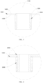
- the pipe joint comprises: a main body portion adapted to abut against an outer surface of a water heater inner tank; and a shoulder portion disposed at the main body portion and adapted to be inserted into the water heater inner tank, the shoulder portion having an end face and a first inner wall surface, and a first curved surface being formed between the end face and the first inner wall surface.
- the first curved surface may be an arc surface.
- the first curved surface may have a radius of R1, where 0.5 mm ⁇ R1 ⁇ 2 mm.
- the shoulder portion may be higher than an inner surface of the water heater inner tank.
- the shoulder portion may have a first outer wall surface, and a second curved surface may be formed between the end face and the first outer wall surface.
- the second curved surface may be an arc surface.
- the second curved surface may have a radius of R2, where 0.5 mm ⁇ R2 ⁇ 2 mm.
- the main body portion may have a second inner wall surface, and the second inner wall surface may have a groove.
- the groove may extend in a circumferential direction of the second inner wall surface.
- the second inner wall surface may have a plurality of grooves arranged at intervals in an axial direction of the main body portion.
- the groove may be formed below half of a height of the main body portion.
- the shoulder portion may define a first through opening.
- the main body portion may define a second through opening.
- the groove may be located adjacent to and in communication with the second through opening.
- the present invention further discloses a water heater.
- the water heater comprises the above-mentioned pipe joint, the water heater inner tank, and a plastic layer disposed at an inner surface of the water heater inner tank and an inner wall surface of the pipe joint.
- the pipe joint may be welded to the outer surface of the water heater inner tank along a circumferential direction of the pipe joint.
- the shoulder portion and the main body portion cooperate to form a step structure, which facilitates an insertion into and positioning with the water heater inner tank.
- the shoulder portion Through forming the shoulder portion with the first curved surface adjacent to the first inner wall surface and the end face, the first curved surface can avoid an obstruction to flow of a raw material when the raw material is coated on the inner surface of the water heater inner tank and the inner wall surface of the pipe joint, which facilitates the flow of the raw material.
- the plastic layer formed in the pipe joint has a uniform thickness. Therefore, the inner wall surface of the pipe joint is better covered by the plastic layer to ensure protection of the pipe joint, preventing a water leakage.
- each orientation indication (such as up, down, left, right, front, rear, ...) in the embodiments of the present invention is used only for explaining a relative positional relation, movements, etc., between components in a particular pose (as illustrated in the figures). If the particular pose is changed, the orientation indication is changed accordingly.
- connection In the present invention, unless otherwise clearly specified and limited, terms such as "connect”, “fix”, and the like should be understood in a broad sense. For example, it may be a fixed connection or a detachable connection or connection as one piece; mechanical connection or electrical connection; direct connection or indirect connection through an intermediate; internal communication of two components or the interaction relationship between two components, unless otherwise clearly limited.
- connect may be a fixed connection or a detachable connection or connection as one piece; mechanical connection or electrical connection; direct connection or indirect connection through an intermediate; internal communication of two components or the interaction relationship between two components, unless otherwise clearly limited.
- the specific meaning of the above-mentioned terms in the present invention can be understood according to specific circumstances.
- a pipe joint 2000 is disclosed.
- the pipe joint 2000 will be described in detail below in conjunction with a water heater.
- the pipe joint 2000 comprises a shoulder portion 2100 and a main body portion 2200.
- the shoulder portion 2100 is disposed at the main body portion 2200.
- the shoulder portion 2100 has a first inner wall surface 2110 and an end face 2130.
- a first curved surface 2140 is formed between the first inner wall surface 2110 and the end face 2130.
- the shoulder portion 2100 and the main body portion 2200 cooperate to form a step structure, which facilitates an insertion into and positioning with the water heater inner tank 1000.
- the shoulder portion 2100 Through forming the shoulder portion 2100 with the first curved surface 2140 adjacent to the first inner wall surface 2110 and the end face 2130, the first curved surface 2140 can avoid an obstruction to flow of a raw material when the raw material is coated on an inner surface 1400 of the water heater inner tank 1000 and an inner wall surface 2001 of the pipe joint 2000, which facilitates the flow of the raw material.
- a plastic layer 4000 formed in the pipe joint 2000 has a uniform thickness. Therefore, the inner wall surface 2001 of the pipe joint 2000 is better covered by the plastic layer 4000 to ensure protection of the pipe joint 2000, preventing a water leakage.
- water heaters are categorized into a gas water heater and an electric water heater.
- the gas water heater heats water using combustion of a gas.
- the electric water heater heats water using heat generated by electricity.
- the present invention describes the water heater as the electric water heater.
- the water heater inner tank 1000 has a water storage cavity 1100 for storing a certain amount of water.
- the water heater inner tank 1000 is mounted with a heater for heating the water in the water storage cavity 1100 under an effect of heating of the heater. It should be understood that the water in the water storage cavity 1100 needs to be supplied from an ambient environment and discharged to the ambient environment after being heated.
- water inlet and water outlet of the water heater are realized through a water inlet joint and a water outlet joint.
- the water inlet joint is mounted at the water heater inner tank 1000 and in communication with the water storage cavity 1100.
- the water inlet joint needs to be connected to an outside water source, e.g., a municipal water source, through a pipeline.
- the municipal water supply transports, via a pipeline, water to the water storage cavity 1100 through the water inlet joint, until a water level in the water storage cavity 1100 reaches a predetermined water level.
- the water outlet joint is also mounted at the water heater inner tank 1000 and in communication with the water storage cavity 1100.
- the water outlet joint needs to be connected to a sprinkler such as a shower through a pipeline.
- the water in the water storage cavity 1100 is outputted through the water outlet joint.
- the water inlet and the water outlet are realized through the water inlet joint and the water outlet joint.
- Both the water inlet joint and the water outlet joint are referred to as the pipe joint 2000.
- the pipe joint 2000 is a joint for realizing flow of water.
- the pipe joint 2000 is not limited to the water inlet joint and the water outlet joint that are described above, and may also be a joint for mounting a drain valve.
- the drain valve is a kind of joint fitting 3000.
- the joint fitting 3000 may be any component connected to the pipe joint 2000.
- the joint fitting may be integrated with a water inlet pipe, a water outlet pile, and so on.
- the pipe joint 2000 and the water heater inner tank 1000 are manufactured separately and then connected together, to facilitate assembly and a connection between the pipe joint 2000 and the water heater inner tank 1000.
- the pipe joint 2000 has the main body portion 2200 and the shoulder portion 2100.
- the shoulder portion 2100 is disposed at the main body portion 2200.
- the shoulder portion 2100 and the main body portion 2200 together form the inner wall surface 2001 of the pipe joint 2000.
- the inner wall surface 2001 of the pipe joint 2000 has a water channel.
- the shoulder portion 2100 has a smaller radial dimension than the main body portion 2200. In this way, the shoulder portion 2100 and the main body portion 2200 cooperate to form the step structure.
- the water heater inner tank 1000 has a mounting hole 1200 in communication with the water storage cavity 1100.
- the shoulder portion 2100 When the pipe joint 2000 is mounted at the water heater inner tank 1000, the shoulder portion 2100 is inserted into the mounting hole 1200 (i.e., into the water heater inner tank 1000). When the shoulder portion 2100 is inserted into the mounting hole 1200 and reaches a predetermined position, the main body portion 2200 abuts against the outer surface 1300 of the water heater inner tank 1000. In this way, preliminary positioning and mounting of the pipe joint 2000 and the water heater inner tank 1000 is formed, laying a foundation for subsequent fastening.
- the shoulder portion 2100 is inserted into the mounting hole 1200 from an outside to an inside, and thus a more sufficient space is provided for mounting operations performed from an outside of the water heater inner tank 1000, which is more convenient for the connection between the pipe joint 2000 and the water heater inner tank 1000.
- the water heater inner tank 1000 is made of plastic or metal. Although the water heater inner tank 1000 made of plastic has advantages such as low cost and corrosion resistance, the water heater inner tank 1000 made of plastic has problems such as easy to aging and short life span. On the contrary, the water heater inner tank 1000 made of metal is less susceptible to aging and has a longer life span, but is more costly and not corrosion-resistant. To prevent corrosion of the water heater inner tank 1000 made of metal, the inner surface 1400 of the water heater inner tank 1000 is coated with polymer (a raw material) to form the plastic layer 4000, which protects the water heater inner tank 1000.
- polymer a raw material
- the pipe joint 2000 is also made of metal, and thus the inner wall surface 2001 of the pipe joint 2000 also needs to be coated with polymer to form the plastic layer 4000 for protecting the pipe joint 2000.
- the water heater inner tank 1000 made of metal has high structural strength to ensure pressure bearing performance, while the plastic layer 4000 realizes satisfactory corrosion resistance.
- the plastic layer 4000 may be coated on each of the inner surface 1400 of the water heater inner tank 1000 and the inner wall surface 2001 of the pipe joint 2000 through rotational molding.
- the polymer is melted by heat and coated on and adhered to the inner surface 1400 of the water heater inner tank 1000 by gravity.
- the polymer in a molten state flows from the inner surface 1400 of the water heater inner tank 1000 to the inner wall surface 2001 of the pipe joint 2000, and is then cooled and shaped to form the plastic layer 4000.
- the shoulder portion 2100 is inserted into the mounting hole 1200, flow of the polymer in the molten state is obstructed if a right angle is formed between the first inner wall surface 2110 and the end face 2130 of the shoulder portion 2100, which leads to an uneven thickness of the plastic layer 4000 formed by the polymer flowing towards the inner wall surface 2001 of the pipe joint 2000, and even leads to bubbles, jeopardizing protection of the pipe joint 2000. Therefore, in this embodiment, the first curved surface 2140 is formed between the end face 2130 and the first inner wall surface 2110.
- the flow of the polymer is facilitated, which is favorable to the flow of the polymer towards the inner wall surface of the pipe joint 2000, allowing the formed plastic layer 4000 to have the uniform thickness and reducing a likelihood of generation of air bubbles.
- the plastic layer 4000 can also be prepared through other processes than the rotational molding. Details of the other processes will be omitted here.
- the first curved surface 2140 is designed as an arc surface. In this way, when the polymer in the molten state flows through the first curved surface 2140, a force of the first curved surface 2140 on the polymer is perpendicular to the first curved surface 2140, which makes the polymer flow through the first curved surface 2140 more stable and less likely to experience a flow disruption.
- the first curved surface 2140 has a radius of R1, where 0.5 mm ⁇ R1 ⁇ 2 mm.
- R1 is 0.5 mm, 1 mm, 1.5 mm, or 2 mm.
- R1 is 1 mm. Therefore, better flow guidance is provided for the polymer in the molten state.
- the shoulder portion 2100 is designed to be higher than the inner surface 1400 of the water heater inner tank 1000, to realize better positioning and mounting of the pipe joint 2000 and the water heater inner tank 1000. It should be understood that, that "higher than” is referenced in an axial direction of the pipe joint 2000 and means that the shoulder portion 2100 needs to protrude into the water storage cavity 1100. A height difference exists between the shoulder portion 2100 and the inner surface 1400 of the water heater inner tank 1000. In this way, during mounting of the pipe joint 2000 and the water heater inner tank 1000, the shoulder portion 2100 is inserted into the mounting hole 1200 to form better interlocking, enabling the pipe joint 2000 to be less likely to wobble.
- the shoulder portion 2100 has a first outer wall surface 2120.
- a second curved surface 2150 is formed between the first outer wall surface 2120 and the end face 2130.
- the second curved surface 2150 is formed between the first outer wall surface 2120 and the end face 2130 considering that the shoulder portion 2100 is higher than the inner surface 1400 of the water heater inner tank 1000.
- the plastic layer 4000 has a more uniform thickness at the junction of the pipe joint 2000 and the water heater inner tank 1000, which forms better protection to avoid a water seepage.
- the second curved surface 2150 is also designed as an arc surface. In this way, when the polymer in the molten state flows through the second curved surface 2150, a force of the second curved surface 2150 on the polymer is perpendicular to the second curved surface 2150, which makes the polymer flow through the second curved surface 2150 more stable and less likely to experience a flow disruption.
- the second curved surface 2150 has a radius of R2, where 0.5 mm ⁇ R2 ⁇ 2 mm.
- R2 is 0.5 mm, 1 mm, 1.5 mm, or 2 mm.
- R2 is 1 mm. Therefore, better flow guidance is provided for the polymer in the molten state.
- the main body portion 2200 has a second inner wall surface 2210.
- the second inner wall surface 2210 has a groove 2211. With the groove 2211, bonding strength between the second inner wall surface 2210 and the plastic layer 4000 is enhanced, preventing the plastic layer 4000 from falling off.
- a connection between the pipe joint 2000 and the joint fitting 3000 is realized through the main body portion 2200.
- an outer wall surface of the main body portion 2200 is defined as a second outer wall surface 2220.
- the second outer wall surface 2220 has external threads.
- the joint fitting 3000 may be connected to the main body portion 2200 through threads to realize flow of water.
- a temperature of the main body portion 2200 becomes lower, which is due to a fact that, the shoulder portion 2100 is located in the water storage cavity 1100 and thus has a relatively higher temperature due to an influence of a temperature of the water, while an end of the main body portion 2200 away from the shoulder portion 2100 is located outside the water storage cavity 1100 and thus has a relatively lower temperature.
- the plastic layer 4000 is susceptible to contraction and detachment from the inner wall surface 2001 of the pipe joint 2000 due to an influence of temperature changes.
- the second inner wall surface 2210 of the main body portion 2200 has the groove 2211.
- the groove 2211 is a space grooveed with respect to the second inner wall surface 2210.
- the polymer in the molten state flows through the second inner wall surface 2210, fills the groove 2211, and can be retained in the groove 2211 during a process of being molded into the plastic layer, enhancing the bonding strength between the plastic layer 4000 and the second inner wall surface 2210 to prevent the plastic layer 4000 from detaching from the second inner wall surface 2210.
- the groove 2211 is open towards a center axis of the main body portion 2200.
- the groove 2211 may have a depth designed to range from 0.5 mm to 1 mm, preferably 0.7 mm, and have an opening width designed to range from 1 mm to 3 mm, preferably 2 mm.
- the groove 2211 is designed to extend in a circumferential direction of the second inner wall surface 2210, which can further enhance the bonding strength between the plastic layer 4000 and the second inner wall surface 2210.
- the groove 2211 is designed to be in a ring shape. In this way, a certain constraining force can be exerted on the plastic layer 4000 in the circumferential direction of the second inner wall surface 2210, which can further inhibit a deformation of the plastic layer 4000 due to the contraction.
- the second inner wall surface 2210 has a plurality of grooves 2211 arranged at intervals in an axial direction of the main body portion 2200.
- the plurality of grooves 2211 mean two and more grooves 2211. Since the pipe joint 2000 needs to be connected to both the water heater inner tank 1000 and the joint fitting 3000, the pipe joint 2000 has a certain length in an axial direction of the pipe joint 2000. Correspondingly, the plastic layer 4000 also needs to be formed through performing coating in the axial direction of the pipe joint 2000. To this end, the plurality of grooves 2211 arranged at intervals are formed to effectively prevent the plastic layer 4000 from detaching from the second inner wall surface 2210 of the main body portion 2200.
- the groove 2211 is formed below half of a height of the main body portion 2200. In this way, effective bonding between the plastic layer 4000 and the second inner wall surface 2210 can be realized to avoid the detachment of the plastic layer 4000. Also, difficulty of processing can be effectively reduced to improve a processing efficiency.
- the so-called height is a length of the pipe joint 2000 in the axial direction of the pipe joint 2000.
- the groove 2211 is formed at the part of the main body portion 2200 below half of the height of the main body portion 2200, which is due to a fact that a possibility that the plastic layer 4000 contracts due to alternating temperature changes increases as the main body portion 2200 becomes further away from the water heater inner tank 1000 and decreases as the main body portion 2200 becomes closer to the water heater inner tank 1000.
- forming the groove 2211 at the part of the main body portion 2200 below half of the height of the main body portion 2200 effectively enhances the bonding strength between the plastic layer 4000 at the part of the main body portion 2200 below half of the height of the main body portion 2200 and the second inner wall surface 2210, without manufacturing the groove 2211 at the second inner wall surface 2210 of the entire main body portion 2200, which improves a manufacturing efficiency.
- the main body portion 2200 defines a second through opening 2003.
- the shoulder portion 2100 defines a first through opening 2002.
- the groove 2211 is located adjacent to and in communication with the second through opening 2003.
- the first through opening 2002 is in (direct or indirect) communication with the water storage cavity 1100.
- the main body portion 2200 is connected to the joint fitting 3000, and thus the second through opening 2003 is in (direct or indirect) communication with the joint fitting 3000.
- the plastic layer 4000 corresponding to the second through opening 2003 is the furthest away from the water heater inner tank 1000 and is most affected by the temperature change. Therefore, one of the plurality of grooves 2211 may be designed to be adjacent to and in communication with the second through opening 2003. In this way, the plastic layer 4000 is better bonded to a periphery of the second through opening 2003 to prevent the plastic layer 4000 corresponding to the entire pipe joint 2000 from being affected due to a separation between the plastic layer 4000 and an end of the main body portion 2200.
- a water heater in a second aspect of the present invention, comprises the pipe joint 2000 according to any of the above embodiments, the water heater inner tank 1000, and the plastic layer 4000.
- the plastic layer 4000 is disposed at the inner wall surface 2001 of the pipe joint 2000 and the inner surface 1400 of the water heater inner tank 1000 to protect the pipe joint 2000 and the water heater inner tank 1000.
- An engagement between the pipe joint 2000, the water heater inner tank 1000, and the plastic layer 4000 is described above and will not be repeated herein. It should be understood that, since the pipe joint 2000 of the water heater according to the embodiment adopts the technical solutions according to the above embodiments, the water heater at least provides the advantageous effects brought about by the technical solutions according to the above embodiments.
- the pipe joint 2000 is inserted into the mounting hole 1200 by means of the shoulder portion 2100, and the main body portion 2200 abuts against the outer surface 1300 of the water heater inner tank 1000.
- the connection between the pipe joint 2000 and the water heater inner tank 1000 is realized through welding. Specifically, at an intersection of the main body portion 2200 and the outer surface 1300 of the water heater inner tank 1000, the main body portion 2200 and the water heater inner tank 1000 are welded together in a circumferential direction of the pipe joint 2000, which is not only easy to operate (there is a sufficient operation space outside the water heater inner tank 1000), but also prevents welding debris from entering the water storage cavity 1100.
Landscapes
- Engineering & Computer Science (AREA)
- General Engineering & Computer Science (AREA)
- Mechanical Engineering (AREA)
- Physics & Mathematics (AREA)
- Thermal Sciences (AREA)
- Chemical & Material Sciences (AREA)
- Combustion & Propulsion (AREA)
- Heat-Pump Type And Storage Water Heaters (AREA)
- Rigid Pipes And Flexible Pipes (AREA)
Applications Claiming Priority (2)
| Application Number | Priority Date | Filing Date | Title |
|---|---|---|---|
| CN202322101899.3U CN220379997U (zh) | 2023-08-03 | 2023-08-03 | 管路接头和热水器 |
| PCT/CN2024/101203 WO2025025912A1 (zh) | 2023-08-03 | 2024-06-25 | 管路接头和热水器 |
Publications (2)
| Publication Number | Publication Date |
|---|---|
| EP4530554A1 true EP4530554A1 (de) | 2025-04-02 |
| EP4530554A4 EP4530554A4 (de) | 2025-10-29 |
Family
ID=89568682
Family Applications (1)
| Application Number | Title | Priority Date | Filing Date |
|---|---|---|---|
| EP24824478.2A Pending EP4530554A4 (de) | 2023-08-03 | 2024-06-25 | Rohrverbindung und wassererhitzer |
Country Status (3)
| Country | Link |
|---|---|
| EP (1) | EP4530554A4 (de) |
| CN (1) | CN220379997U (de) |
| WO (1) | WO2025025912A1 (de) |
Families Citing this family (1)
| Publication number | Priority date | Publication date | Assignee | Title |
|---|---|---|---|---|
| CN220379997U (zh) * | 2023-08-03 | 2024-01-23 | 芜湖美的智能厨电制造有限公司 | 管路接头和热水器 |
Family Cites Families (8)
| Publication number | Priority date | Publication date | Assignee | Title |
|---|---|---|---|---|
| DE2634153C2 (de) * | 1976-07-29 | 1987-01-15 | Alligator Ventilfabrik GmbH, 7928 Giengen | Ventil für einen schlauchlosen Reifen |
| CN201081386Y (zh) * | 2007-09-05 | 2008-07-02 | 赵松盛 | 双内胆电热水器 |
| US8869399B2 (en) * | 2011-07-21 | 2014-10-28 | Miclau S.R.I. Inc. | Method of constructing an inner glass-lined steel tank for a hot water heater |
| CN212868644U (zh) * | 2020-07-23 | 2021-04-02 | 北京天海工业有限公司 | 一种非金属内胆全缠绕气瓶瓶口金属阀座 |
| CN115388560A (zh) * | 2022-08-15 | 2022-11-25 | 江苏光芒智慧能源有限公司 | 一种搪瓷内胆热水器的内胆封头 |
| CN219177986U (zh) * | 2022-08-26 | 2023-06-13 | 青岛经济技术开发区海尔热水器有限公司 | 扁平式内胆及电热水器 |
| CN115993003A (zh) * | 2022-12-05 | 2023-04-21 | 芜湖美的智能厨电制造有限公司 | 内胆结构及电热水器 |
| CN220379997U (zh) * | 2023-08-03 | 2024-01-23 | 芜湖美的智能厨电制造有限公司 | 管路接头和热水器 |
-
2023
- 2023-08-03 CN CN202322101899.3U patent/CN220379997U/zh active Active
-
2024
- 2024-06-25 EP EP24824478.2A patent/EP4530554A4/de active Pending
- 2024-06-25 WO PCT/CN2024/101203 patent/WO2025025912A1/zh active Pending
Also Published As
| Publication number | Publication date |
|---|---|
| WO2025025912A1 (zh) | 2025-02-06 |
| EP4530554A4 (de) | 2025-10-29 |
| CN220379997U (zh) | 2024-01-23 |
Similar Documents
| Publication | Publication Date | Title |
|---|---|---|
| EP4530554A1 (de) | Rohrverbindung und wassererhitzer | |
| CN107830668A (zh) | 一种冰箱制冰机的进水组件及冰箱 | |
| CN107816592B (zh) | 用于连接金属复合管材的管件 | |
| CN201007410Y (zh) | 一种带螺纹连接的管件 | |
| JP2004217017A (ja) | ヒータ用配管、ジョイント、ヒータ用配管とジョイントとの接続構造 | |
| JP5829114B2 (ja) | 配管材及びその製造方法 | |
| CN216867870U (zh) | 一种防泄漏大流量活接管件 | |
| JP5688282B2 (ja) | 配管材の製造方法 | |
| CN209115820U (zh) | 双壁波纹管连接装置及带有扩口的塑料双壁波纹管 | |
| CN112524260A (zh) | 电子膨胀阀以及制冷设备 | |
| CN212510007U (zh) | 管件及复合管件 | |
| CN203629039U (zh) | 热水器内胆和具有其的热水器 | |
| CN212673497U (zh) | 热水器及其进水管组件 | |
| CN202091662U (zh) | 塑钢缠绕管顺插口结构 | |
| JP2024545746A (ja) | 給湯器用の配管部材、配管アセンブリおよびその給湯器 | |
| CN209229208U (zh) | 埋线式自体限位型的电熔管件 | |
| CN209726522U (zh) | 全塑料内胆承压储热水箱 | |
| CN215674021U (zh) | 一种钢塑复合管连接结构 | |
| CN221629115U (zh) | 一种防缩径管接头 | |
| JP2005090704A (ja) | 融着サドル付き分水栓継手 | |
| CN222479806U (zh) | 一种电熔弯头连接器 | |
| CN213900157U (zh) | 一种增强型内衬复合管 | |
| CN219975771U (zh) | 一种用于ppr管熔接区域的内衬管件 | |
| CN224003934U (zh) | 排气工装及内胆 | |
| CN223768212U (zh) | 一种可丝接承插的非金属阀门 |
Legal Events
| Date | Code | Title | Description |
|---|---|---|---|
| STAA | Information on the status of an ep patent application or granted ep patent |
Free format text: STATUS: UNKNOWN |
|
| STAA | Information on the status of an ep patent application or granted ep patent |
Free format text: STATUS: THE INTERNATIONAL PUBLICATION HAS BEEN MADE |
|
| PUAI | Public reference made under article 153(3) epc to a published international application that has entered the european phase |
Free format text: ORIGINAL CODE: 0009012 |
|
| STAA | Information on the status of an ep patent application or granted ep patent |
Free format text: STATUS: REQUEST FOR EXAMINATION WAS MADE |
|
| 17P | Request for examination filed |
Effective date: 20241224 |
|
| AK | Designated contracting states |
Kind code of ref document: A1 Designated state(s): AL AT BE BG CH CY CZ DE DK EE ES FI FR GB GR HR HU IE IS IT LI LT LU LV MC ME MK MT NL NO PL PT RO RS SE SI SK SM TR |
|
| REG | Reference to a national code |
Ref country code: DE Ref legal event code: R079 Free format text: PREVIOUS MAIN CLASS: F24H0009130000 Ipc: F16L0041080000 |
|
| A4 | Supplementary search report drawn up and despatched |
Effective date: 20250930 |
|
| RIC1 | Information provided on ipc code assigned before grant |
Ipc: F16L 41/08 20060101AFI20250924BHEP Ipc: F16L 58/10 20060101ALI20250924BHEP Ipc: F24H 1/18 20220101ALI20250924BHEP Ipc: F16L 13/02 20060101ALN20250924BHEP |