EP4530509A1 - Steuerventil - Google Patents
Steuerventil Download PDFInfo
- Publication number
- EP4530509A1 EP4530509A1 EP23811024.1A EP23811024A EP4530509A1 EP 4530509 A1 EP4530509 A1 EP 4530509A1 EP 23811024 A EP23811024 A EP 23811024A EP 4530509 A1 EP4530509 A1 EP 4530509A1
- Authority
- EP
- European Patent Office
- Prior art keywords
- communication
- port
- communication port
- connection port
- connection
- Prior art date
- Legal status (The legal status is an assumption and is not a legal conclusion. Google has not performed a legal analysis and makes no representation as to the accuracy of the status listed.)
- Pending
Links
Images


Classifications
-
- F—MECHANICAL ENGINEERING; LIGHTING; HEATING; WEAPONS; BLASTING
- F16—ENGINEERING ELEMENTS AND UNITS; GENERAL MEASURES FOR PRODUCING AND MAINTAINING EFFECTIVE FUNCTIONING OF MACHINES OR INSTALLATIONS; THERMAL INSULATION IN GENERAL
- F16K—VALVES; TAPS; COCKS; ACTUATING-FLOATS; DEVICES FOR VENTING OR AERATING
- F16K11/00—Multiple-way valves, e.g. mixing valves; Pipe fittings incorporating such valves
- F16K11/02—Multiple-way valves, e.g. mixing valves; Pipe fittings incorporating such valves with all movable sealing faces moving as one unit
- F16K11/08—Multiple-way valves, e.g. mixing valves; Pipe fittings incorporating such valves with all movable sealing faces moving as one unit comprising only taps or cocks
- F16K11/087—Multiple-way valves, e.g. mixing valves; Pipe fittings incorporating such valves with all movable sealing faces moving as one unit comprising only taps or cocks with spherical plug
- F16K11/0873—Multiple-way valves, e.g. mixing valves; Pipe fittings incorporating such valves with all movable sealing faces moving as one unit comprising only taps or cocks with spherical plug the plug being only rotatable around one spindle
- F16K11/0876—Multiple-way valves, e.g. mixing valves; Pipe fittings incorporating such valves with all movable sealing faces moving as one unit comprising only taps or cocks with spherical plug the plug being only rotatable around one spindle one connecting conduit having the same axis as the spindle
-
- F—MECHANICAL ENGINEERING; LIGHTING; HEATING; WEAPONS; BLASTING
- F16—ENGINEERING ELEMENTS AND UNITS; GENERAL MEASURES FOR PRODUCING AND MAINTAINING EFFECTIVE FUNCTIONING OF MACHINES OR INSTALLATIONS; THERMAL INSULATION IN GENERAL
- F16K—VALVES; TAPS; COCKS; ACTUATING-FLOATS; DEVICES FOR VENTING OR AERATING
- F16K11/00—Multiple-way valves, e.g. mixing valves; Pipe fittings incorporating such valves
- F16K11/02—Multiple-way valves, e.g. mixing valves; Pipe fittings incorporating such valves with all movable sealing faces moving as one unit
- F16K11/08—Multiple-way valves, e.g. mixing valves; Pipe fittings incorporating such valves with all movable sealing faces moving as one unit comprising only taps or cocks
- F16K11/087—Multiple-way valves, e.g. mixing valves; Pipe fittings incorporating such valves with all movable sealing faces moving as one unit comprising only taps or cocks with spherical plug
- F16K11/0873—Multiple-way valves, e.g. mixing valves; Pipe fittings incorporating such valves with all movable sealing faces moving as one unit comprising only taps or cocks with spherical plug the plug being only rotatable around one spindle
-
- F—MECHANICAL ENGINEERING; LIGHTING; HEATING; WEAPONS; BLASTING
- F01—MACHINES OR ENGINES IN GENERAL; ENGINE PLANTS IN GENERAL; STEAM ENGINES
- F01P—COOLING OF MACHINES OR ENGINES IN GENERAL; COOLING OF INTERNAL-COMBUSTION ENGINES
- F01P7/00—Controlling of coolant flow
- F01P7/14—Controlling of coolant flow the coolant being liquid
- F01P7/16—Controlling of coolant flow the coolant being liquid by thermostatic control
- F01P7/165—Controlling of coolant flow the coolant being liquid by thermostatic control characterised by systems with two or more loops
-
- F—MECHANICAL ENGINEERING; LIGHTING; HEATING; WEAPONS; BLASTING
- F16—ENGINEERING ELEMENTS AND UNITS; GENERAL MEASURES FOR PRODUCING AND MAINTAINING EFFECTIVE FUNCTIONING OF MACHINES OR INSTALLATIONS; THERMAL INSULATION IN GENERAL
- F16K—VALVES; TAPS; COCKS; ACTUATING-FLOATS; DEVICES FOR VENTING OR AERATING
- F16K11/00—Multiple-way valves, e.g. mixing valves; Pipe fittings incorporating such valves
- F16K11/02—Multiple-way valves, e.g. mixing valves; Pipe fittings incorporating such valves with all movable sealing faces moving as one unit
- F16K11/08—Multiple-way valves, e.g. mixing valves; Pipe fittings incorporating such valves with all movable sealing faces moving as one unit comprising only taps or cocks
- F16K11/085—Multiple-way valves, e.g. mixing valves; Pipe fittings incorporating such valves with all movable sealing faces moving as one unit comprising only taps or cocks with cylindrical plug
-
- F—MECHANICAL ENGINEERING; LIGHTING; HEATING; WEAPONS; BLASTING
- F16—ENGINEERING ELEMENTS AND UNITS; GENERAL MEASURES FOR PRODUCING AND MAINTAINING EFFECTIVE FUNCTIONING OF MACHINES OR INSTALLATIONS; THERMAL INSULATION IN GENERAL
- F16K—VALVES; TAPS; COCKS; ACTUATING-FLOATS; DEVICES FOR VENTING OR AERATING
- F16K27/00—Construction of housing; Use of materials therefor
- F16K27/06—Construction of housing; Use of materials therefor of taps or cocks
- F16K27/067—Construction of housing; Use of materials therefor of taps or cocks with spherical plugs
-
- F—MECHANICAL ENGINEERING; LIGHTING; HEATING; WEAPONS; BLASTING
- F16—ENGINEERING ELEMENTS AND UNITS; GENERAL MEASURES FOR PRODUCING AND MAINTAINING EFFECTIVE FUNCTIONING OF MACHINES OR INSTALLATIONS; THERMAL INSULATION IN GENERAL
- F16K—VALVES; TAPS; COCKS; ACTUATING-FLOATS; DEVICES FOR VENTING OR AERATING
- F16K31/00—Actuating devices; Operating means; Releasing devices
- F16K31/44—Mechanical actuating means
- F16K31/53—Mechanical actuating means with toothed gearing
- F16K31/535—Mechanical actuating means with toothed gearing for rotating valves
-
- F—MECHANICAL ENGINEERING; LIGHTING; HEATING; WEAPONS; BLASTING
- F16—ENGINEERING ELEMENTS AND UNITS; GENERAL MEASURES FOR PRODUCING AND MAINTAINING EFFECTIVE FUNCTIONING OF MACHINES OR INSTALLATIONS; THERMAL INSULATION IN GENERAL
- F16K—VALVES; TAPS; COCKS; ACTUATING-FLOATS; DEVICES FOR VENTING OR AERATING
- F16K5/00—Plug valves; Taps or cocks comprising only cut-off apparatus having at least one of the sealing faces shaped as a more or less complete surface of a solid of revolution, the opening and closing movement being predominantly rotary
- F16K5/04—Plug valves; Taps or cocks comprising only cut-off apparatus having at least one of the sealing faces shaped as a more or less complete surface of a solid of revolution, the opening and closing movement being predominantly rotary with plugs having cylindrical surfaces; Packings therefor
- F16K5/0457—Packings
- F16K5/0471—Packings between housing and plug
-
- F—MECHANICAL ENGINEERING; LIGHTING; HEATING; WEAPONS; BLASTING
- F01—MACHINES OR ENGINES IN GENERAL; ENGINE PLANTS IN GENERAL; STEAM ENGINES
- F01P—COOLING OF MACHINES OR ENGINES IN GENERAL; COOLING OF INTERNAL-COMBUSTION ENGINES
- F01P7/00—Controlling of coolant flow
- F01P7/14—Controlling of coolant flow the coolant being liquid
- F01P2007/146—Controlling of coolant flow the coolant being liquid using valves
Definitions
- the present application relates to the technical field of fluid control, and in particular to a control valve.
- a thermal management system uses multi-way control valves to control flow paths, and the control valves have more than two operating modes.
- the control valve includes a valve body and a valve core, where the valve core is rotatably arranged in a valve cavity inside the valve body.
- the valve body is provided with multiple communication ports located at an inner wall of the valve cavity.
- the multiple communication ports are located at a same height.
- the communication ports are arranged along the circumferential direction of the valve cavity, and thus the circumferential length or radial size of the valve cavity is large, which leads to a large flow resistance of the fluid through the control valve indirectly.
- An object of the present application is to provide a control valve, to reduce a radial size of a valve cavity.
- a control valve including a valve body assembly and a valve core assembly, where the control valve has a valve cavity, and the valve core assembly is at least partially located in the valve cavity.
- the valve body assembly is provided with a communication port, and the communication port is located on a wall defining the valve cavity.
- the communication port includes a first communication port, a second communication port, a third communication port, a fourth communication port and a fifth communication port.
- the valve core assembly is provided with a first communicating portion and a second communicating portion.
- the second communicating portion In a first operating position of the valve core assembly, the second communicating portion is in communication with the first communication port, the second communicating portion is in communication with the fourth communication port, the first communicating portion is in communication with the second communication port, and the first communicating portion is in communication with the third communication port.
- the second communicating portion In a second operating position of the valve core assembly, the second communicating portion is in communication with the first communication port, the second communicating portion is in communication with the fifth communication port, the first communicating portion is in communication with the second communication port, and the first communicating portion is in communication with the third communication port.
- a height direction is defined, which is parallel to an extension direction of the valve core axis of the valve core assembly, and in the height direction, the second communication port and the third communication port are provided in a staggered manner.
- the second communication port and the third communication port are provided in a staggered manner, which reduces the number of the communication ports located at the same height, and thereby decreasing the radial size of the valve cavity.
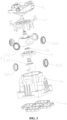
- a control valve 200 includes a valve body assembly 1, a valve core assembly 2 and a driving part 5.
- the valve body assembly 1 has a valve cavity 100, the valve core assembly 2 is at least partially located in the valve cavity 100, and the valve core assembly 2 can be driven by the driving part 5 to rotate.
- the valve core assembly 2 can rotate around a valve core axis X-X, and a position detection element may be provided in the driving part 5 for detecting a rotation angle of the valve core assembly 2.
- a height direction is defined as H, which is parallel or substantially parallel to an extension direction of the valve core axis of the valve core assembly 2.
- valve core axis refers to the valve core axis of the valve core assembly 2
- circumferential direction refers to the circumferential direction of the valve core assembly 2
- radial direction refers to the radial direction of the valve core assembly 2 or a direction parallel to the radial direction of the valve core assembly 2.
- the valve body assembly 1 has seven communication ports, including a first communication port 101, a second communication port 102, a third communication port 103, a fourth communication port 104, a fifth communication port 105, a sixth communication port 106 and a seventh communication port 107.
- the seven communication ports are located at a wall defining the valve cavity 100.
- the valve body assembly 1 has five connection ports, including a first connection port 111, a second connection port 112, a third connection port 113, a fourth connection port 114 and a fifth connection port 115.
- the second communication port 102 is in communication with the third connection port 113
- the fifth communication port 105 is in communication with the first connection port 111
- the fourth communication port 104 is in communication with the fifth connection port 115
- the third communication port 103 is in communication with the fourth connection port 114
- both the first communication port 101 and the sixth communication port 106 are in communication with the second connection port 112
- both the seventh communication port 107 and the third communication port 103 are in communication with the fourth connection port 114.
- a part of the valve core assembly 2 located in the valve cavity 100 has a first communicating portion 211 and a second communicating portion 221, and each of the communicating portions is able to communicate two or more communication ports to realize communication between at least two connection ports.
- the valve core assembly 2 can open or close the communication ports. "Closing the communication port” means cutting off the communication or circulation between the communication port and the valve cavity 100, and "opening the communication port” means communicating the communication port with the valve cavity 100 or communicating the communication port with at least one of the communicating portions.
- the first communicating portion 211 includes a first communicating cavity and a wall portion defining the first communicating cavity.
- the second communicating portion 221 includes a second communicating cavity and a wall portion defining the second communicating cavity.
- the valve body assembly 1 includes a valve cover 17, a housing 16, and a partition wall portion 11.
- the partition wall portion 11 is at least partially located in the housing 16, and the valve cover 17 closes an opening at an upper end of the housing 16.
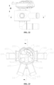
- the valve body assembly 1 includes a first cavity 3 and a second cavity 4, where at least part of the first cavity 3 and at least part of the second cavity 4 are located at different heights of the valve body assembly 1, and the partition wall portion 11 separates the first cavity 3 from the second cavity 4.
- a temperature of a fluid in the first cavity 3 may be different from a temperature of a fluid in the second cavity 4.
- the partition wall portion 11 can separate the fluid in the first cavity 3 from the fluid in the second cavity 4, thus reducing the mixing of the fluid in the first cavity 3 and the fluid in the second cavity 4, and thereby improving the thermal efficiency.
- the second communication port 102, the sixth communication port 106 and the third communication port 103 are provided at the wall defining the first cavity 3, and the fourth communication port 104, the fifth communication port 105, the first communication port 101 and the seventh communication port 107 are provided at the wall defining the second cavity 4.
- the first communicating portion 211 is located in the first cavity 3, and the communicating portion 221 is located in the second cavity 4.
- the partition wall portion 11 has a first through hole 19, and a part of the valve core assembly 2 is located in the first through hole 19.
- the partition wall portion 11 is hermetically arranged with the valve core assembly 2, and the partition wall portion 11 is hermetically arranged with the housing 16.
- the partition wall portion 11 is welded with the housing 16, or in an interference fit with the housing 16, or integrally formed with the housing 16.
- the partition wall portion 11 is integrally formed with the valve core assembly 2, and the partition wall portion 11 is slidably sealed with the wall defining the valve cavity 100. Or, the partition wall portion 11 is slidably sealed with the housing 16. This integrally formed valve core assembly 2 is convenient to assemble.
- the valve core assembly 2 includes a first valve core portion 21 and a second valve core portion 22.
- the first valve core portion 21 and the second valve core portion 22 are arranged along an axial direction of the valve core assembly 2, and the first valve core portion 21 is in transmission connection with the second valve core portion 22.
- the first communicating portion 211 is located in the first valve core portion 21, and the second communicating portion 221 is located in the second valve core portion 22.
- the second valve core portion 22 can drive the first valve core portion 21 to rotate, so as to allow the transmission connection therebetween.
- the second valve core portion 22 and the first valve core portion 21 may be directly connected to each other or may be in transmission connection with each other via other components.
- the first valve core portion 21 is located in the first cavity 3, and the second valve core portion 22 is located in the second cavity 4.
- An outer wall of the first valve core portion 21 is a part of a virtual spherical shape, and the sixth communication port 106 and the third communication port 103 can face the outer wall of the first valve core portion 21.
- the outer wall of the first valve core portion 21 may also be a part of a virtual column shape or a part of another revolving body.
- An outer wall of the second valve core portion 22 is a part of a virtual spherical shape, and the fourth communication port 104, the fifth communication port 105, the first communication port 101 and the seventh communication port 107 can face the outer wall of the second valve core portion 22.
- the outer wall of the second valve core portion 22 may also be a part of a virtual column shape or a part of another revolving body, and a revolving axis of the revolving body is the valve core axis of the valve core assembly 2.
- the wall defining the valve cavity 100 includes a side wall 12 and a bottom wall 14.
- the bottom wall 14 is located on one side of the valve body assembly 1.
- the side wall 12 extends in the height direction, and the side wall 12 circumferentially surrounds the valve cavity 100.
- the control valve includes at least one first sealing member 521, at least one second sealing member 522 and a third sealing member 18.
- the first sealing member 521 is located between the wall defining the first cavity 3 and the first valve core portion 21, and the second sealing member 522 is located between the wall defining the second cavity 4 and the second valve core portion 22.
- the first sealing member 521 and the second sealing member 522 cooperate with the valve core assembly 2 to close or open the communication port.
- one of the first sealing members 521 is located around the sixth communication port 106 and another one of the first sealing members 521 is located around the third communication port 103.
- a part of the first sealing member 521 is complementary to the shape of the outer wall of the first valve core portion 21 and is sealingly contact with the outer wall of the first valve core portion 21.
- One of the second sealing members 522 is located around the fourth communication port 104, another one of the second sealing members 522 is located around the fifth communication port 105, yet another one of the second sealing members 522 is located around the first communication port 101, and still another one of the second sealing members 522 is located around the seventh communication port 107.
- a part of the second sealing member 522 is complementary in shape to the outer wall of the second valve core portion 22 and is sealingly contact with the outer wall of the second valve core portion 22.
- the third sealing member18 is in contact with the valve core assembly 2 and the partition wall portion 11.
- the third sealing member 18 is used to prevent fluid exchange between the first cavity 3 and the second cavity 4 through the first through hole 19.
- the third sealing member 18 may be a sealing ring with a cross section of an "X" shape.
- the fourth communication port 104, the fifth communication port 105, the first communication port 101 and the seventh communication port 107 are located in substantially a same height range and at different radial directions.
- the third communication port 103 and the sixth communication port 106 are located in substantially a same height range and at different radial directions.
- the second communication port 102 and the sixth communication port 106 are located at different heights. That is, the communication ports are located in at least two different height ranges.
- This arrangement is beneficial to reducing the number of ports in the same height range, in other words, reducing the positions occupied by the connection ports in the same height range, thereby reducing size of the valve cavity 100 and the valve core assembly 2 in the radial direction, which makes the fluid resistance of the control valve relatively small and the torque required to rotate the valve core assembly 2 relatively small.
- such arrangement of the communication ports makes the size of the control valve in the radial direction relatively compact, which facilitates integration with a flow passage plate, in other words, a mounting area of the flow passage plate for mounting with the control valve can be relatively small.
- the communication ports may meet following requirements: a middle part of an opening of the sixth communication port 106 is located at a height within a height range of an opening of the third communication port 103, a middle part of an opening of the fifth communication port 105 is located at a height within a height range of an opening of the first communication port 101, a middle part of an opening of the fourth communication port 104 is located at a height within the height range of the opening the first communication port 101, and a middle part of an opening of the seventh communication port 107 is located at a height within the height range of the opening of the first communication port 101.
- the first communication port 101 and the third communication port 103 are arranged in a staggered manner.
- the first communication port 101, the sixth communication port 106, the third communication port 103, the fourth communication port 104, the fifth communication port 105 and the seventh communication port 107 are all located at the side wall 12, and the second communication port 102 is located at the bottom wall 14.
- the second communication port 102 and the third communication port 103 are arranged in a staggered manner, so that the second communication port 102, the first communication port 101 and the third communication port 103 are located at different heights. That is to say, the communication ports are distributed in at least three different height ranges, which can further reduce the size of the valve cavity 100 and the valve core assembly 2 in the radial direction.
- the second communication port 102 is located at one side of the first valve core portion 21.
- the first valve core portion 21 only two of the communication ports are provided in the circumferential direction of the first valve core portion 21, which can reduce the size of the first valve core portion 21 in the radial direction and further reduce the torque for rotating the first valve core portion 21.
- a part of the first communicating portion 211 is coaxial with the valve core axis and is provided with an opening at an axial side of the valve core of the first valve core portion 21.
- the first communicating portion 211 is always in communication with the second communication port 102.
- the first valve core portion 21 is provided in a form of an on-off valve, which only needs to be able to selectively close the third communication port 103 or the sixth communication port 106 and does not need to have a function of adjusting the flow rate.
- a center of the second communication port 102 is provided coaxially or substantially coaxially with the valve core axis of the valve core assembly 2.
- the size of the first valve core portion 21 in the radical direction is smaller than that of the second valve core portion 22, that is, the valve core assembly 2 has a structure with a large upper part and a small lower part.
- the first valve core portion 21 with a small diameter is mounted in the valve cavity 100 firstly, and then the partition wall portion 11 and the second valve core portion 22 with a large diameter are mounted in the valve cavity 100, which facilitates mounting the valve core assembly 2 into the valve cavity 100 from an upper opening of the housing 16.
- Both the first communication port 101 and the sixth communication port 106 are in communication with a flow passage of the control valve.
- the first communication port 101 and the sixth communication port 106 are located in substantially the same radial direction, so that the flow passage for connecting the first communication port 101 and the sixth communication port 106 is short in length and relatively compact in volume.
- the seventh communication port 107 and the third communication port 103 are located in substantially the same radial direction. In other embodiments, a certain deviation is permissible between the communication ports, and the sizes of the communication ports may be different.
- the center of the first communication port 101 and the center of the sixth communication port 106 are arranged around the valve core axis at an interval of 0 degrees to 10 degrees
- the center of the seventh communication port 107 and the center of the third communication port 103 are arranged around the valve core axis at an interval of 0 degrees to 10 degrees .
- the valve core assembly 2 is able to rotate or slide along the height direction H relative to the valve body assembly 1.
- the second communicating portion 221 is in communication with the first communication port 101
- the second communicating portion 221 is in communication with the fourth communication port 104
- the first communicating portion 211 is in communication with the second communication port 102
- the first communicating portion 211 is in communication with the third communication port 103.
- the second communicating portion 221 is in communication with the first communication port 101
- the first communication port 101 is in communication with the fifth communication port 105
- the first communicating portion 211 is in communication with the second communication port 102
- the first communicating portion 211 is in communication with the third communication port 103.
- valve body assembly 1 has seven communication ports and five connection ports.
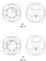
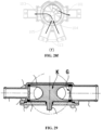
- the valve body assembly 2 is rotated to different operating positions relative to the valve body assembly 1 to achieve different operating modes, as shown in FIG. 13 to FIG. 18 .
- Unidirectional arrows in FIG. 13 to FIG. 18 show one type of flow path of the fluid within the control valve 100, and the control valve 100 in this embodiment has at least six operating modes.
- the third connection port 113 is in communication with the fourth connection port 114 through the second communication port 102, the first communicating portion 211 and the third communication port 103.
- the second connection port 112 is in communication with the fifth connection port 115 through the first communication port 101, the second communicating portion 221 and the fourth communication port 104.
- the first connection port 111 is not in communication with any other connection ports.
- the third connection port 113 is in communication with the fourth connection port 114 through the second communication port 102, the first communicating portion 211 and the third communication port 103.
- the second connection port 112 is in communication with the first connection port 111 through the first communication port 101, the second communicating portion 221 and the fifth communication port 105.
- the fifth connection port 115 is not in communication with any other connection ports.
- the third connection port 113 is in communication with the second connection port 112 through the second communication port 102, the first communicating portion 211 and the sixth communication port 106.
- the fourth connection port 114 is in communication with the first connection port 111 through the seventh communication port 107, the second communicating portion 221 and the fifth communication port 105.
- the fifth connection port 115 is not in communication with any other connection ports.
- the third connection port 113 is in communication with the second connection port 112 through the second communication port 102, the first communicating portion 211 and the sixth communication port 106.
- the fourth connection port 114 is in communication with the fifth connection port 115 through the seventh communication port 107, the second communicating portion 221 and the fourth communication port 104.
- the first connection port 111 is not in communication with any other connection ports.
- the third connection port 113 is in communication with the fourth connection port 114 through the second communication port 102, the first communicating portion 211 and the third communication port 103.
- the second connection port 112 is in communication with the fifth connection port 115 through the first communication port 101, the second communicating portion 221 and the fourth communication port 104.
- the second connection port 112 is in communication with the first connection port 111 through the first communication port 101, the second communicating portion 221 and the fifth communication port 105.
- both the first connection port 111 and the fifth connection port 115 are in communication with the second connection port 112, and a ratio of a flow amount flowing into the second connection port 112 from the first connection port 111 to a flow amount flowing into the second connection port 112 from the fifth connection port 115 can be adjusted by controlling the valve core assembly 2. For example, in FIG. 17 , in the flow amount of the fluid flowing into the second connection port 112, 50% of the flow amount is from the first connection port 111 and 50% of the flow amount is from the fifth connection port 115.
- the third connection port 113 is in communication with the second connection port 112 through the second communication port 102, the first communicating portion 211 and the sixth communication port 106.
- the fourth connection port 114 is in communication with the first connection port 111 through the seventh communication port 107, the second communicating portion 221 and the fifth communication port 105.
- the fourth connection port 114 is in communication with the fifth connection port 115 through the seventh communication port 107, the second communicating portion 221 and the fourth communication port 104.
- both the first connection port 111 and the fifth connection port 115 are in communication with the fourth connection port 114, and a ratio of a flow amount flowing into the fourth connection port 114 from the first connection port 111 to a flow amount flowing into the fourth connection port 114 from the fifth connection port 115 can be adjusted by controlling the valve core assembly 2. For example, in FIG. 18 , in the flow amount of the fluid flowing into the fourth connection port 114, 50% of the flow amount is from the first connection port 111 and 50% of the flow amount is from the fifth connection port 115.
- the control valve In the first operating mode (a), the second operating mode (b), the third operating mode (c) and the fourth operating mode (d), the control valve has only a communication function without a flow amount adjustment function, whereas in the fifth operating mode (e) and the sixth operating mode (f), the control valve has the flow amount adjustment function.
- Both the first communication port 101 and the sixth communication port 106 are in communication with the second connection port 112, that is, the two communication ports share a common connection port, therefore, the second connection port 112 can be selectively in communication with at least three other connection ports, thus increasing the function of the second connection port 112, in addition, the structure of the valve core assembly 2 is relatively simple and there are less communicating portions.
- both the seventh communication port 107 and the third communication port 103 are in communication with the fourth connection port 114, therefore, the fourth connection port 114 can be selectively in communication with at least three other connection ports, thus increasing the function of the fourth connection port 114.
- the first connection port 111, the fifth connection port 115 and the third connection port 113 are fluid inlets, and the second connection port 112 and the fourth connection port 114 are fluid outlets.
- the fifth connection port 115 and the third connection port 113 are fluid outlets, and the first connection port 111, the second connection port 112 and the fourth connection port 114 are fluid inlets, in this case, in the fifth operating mode (e), a ratio of the flow amount flowing from the second connection port 112 into the first connection port 111 to a flow amount flowing from the second connection port 112 into the fifth connection port 115 can be adjusted by controlling the valve core assembly 2; and in the sixth operating mode (f), a ratio of the flow amount flowing from the fourth connection port 114 into the first connection port 111 to a flow amount flowing from the fourth connection port 114 into the fifth connection port 115 can be adjusted by controlling the valve core assembly 2.
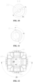
- the fourth communication port 104, the first communication port 101, the fifth communication port 105 and the seventh communication port 107 are circumferentially distributed in the listed sequence.
- a center of the first communication port 101 and a center of the seventh communication port 107 are arranged around the valve core axis at an interval of 120 degrees to 180 degrees, where the interval angle is indicated by ⁇ 2 in FIG. 12 .
- a center of the fourth communication port 104 and a center of the fifth communication port 105 are arranged around the valve core axis at an interval of 120 degrees to 180 degrees, where the interval angle is indicated by ⁇ 1 in FIG. 12 .
- the second valve core portion 22 is able to close any two adjacent communication ports among the fourth communication port 104, the fifth communication port 105, the first communication port 101 and the seventh communication port 107, and at the same time, the second communicating portion 221 are able to communicate the other two adjacent communication ports. Accordingly, the center of the sixth communication port 106 and the center of the third communication port 103 are arranged around the valve core axis at an interval of 120 degrees to 180 degrees .
- the first communication port 101, the fourth communication port 104, the fifth communication port 105, and the seventh communication port 107 are surroundingly and symmetrically along the circumferential direction of the valve core assembly 2, that is, the above four communication ports are arranged in a cross-shape.
- This arrangement of the communication ports can further reduce the size of the valve cavity 100 in the radial direction, resulting in a relatively small fluid resistance and a relatively compact volume of the control valve.
- the first operating mode (a), the second operating mode (b), the third operating mode (c) and the fourth operating mode (d) only have the communication function, and correspond to four different operating positions of the valve core assembly 2, respectively.
- the control valve maintains the operating mode unchanged.
- the range is larger, that is, the sealing range of the control valve is larger, which relatively reduces the requirement for the control accuracy of the valve core assembly 2.
- the permissible control deviation of the rotation angle of the valve core assembly 2 may be up to 5 degrees.
- the first communicating portion 211 has a first opening 212 at the outer wall of the valve core assembly 2
- the second communicating portion 221 has a second opening 222 at the outer wall of the valve core assembly 2.
- the first opening 212 and the second opening 222 are located at different heights along the height direction H.
- the first opening 212 and the sixth communication port 106 are located in substantially the same height range, and the sixth communication port 106 and the second communication port 102 are located in substantially the same height range, which enables the first opening 212 to at least partially face one or both of the second communication port 102 and the sixth communication port 106.
- the second opening 222 is located in substantially the same height range as the first communication port 101, and the first communication port 101 is located in substantially the same height range as the fourth communication port 104, the fifth communication port 105 and the seventh communication port 107, which enables the second opening 222 to at least partially face one or two of the fourth communication port 104, the fifth communication port 105, the first communication port 101 and the seventh communication port 107.
- a certain deviation is permissible between the above openings and the communication ports, and the sizes of the communication ports may be different.
- the middle part of the first opening 212 is located at a height in the height range of the opening of the sixth communication port 106
- the middle part of the second opening 222 is located at a height in the height range of the opening of the first communication port 101.
- the second communicating portion 221 has only the second opening 222 within the height range of the second opening 222.
- the second valve core portion 22 is provided with only one communicating portion, that is, the second communicating portion 221. Therefore, in a case that the radial size of the second valve core portion 22 remains unchanged, the second opening 222 can be provided with a larger size, and a flow area of the second communicating portion 221 can be larger, so as to reduce the flow resistance of the fluid flowing through the second communicating portion 221.
- two ends of the second opening 222 along the circumferential direction are located around the valve core axis at an interval of 160 degrees to 200 degrees, where the interval angle is indicated by ⁇ 2 in FIG. 11 , so that the second communicating portion 221 has a large span in the circumferential direction, and is able to be in communication with three communication ports at the same time, thereby realizing the function of flow amount adjustment in the fifth operating mode (e) and the sixth operating mode (f).
- a part of the outer wall of the valve core assembly 2 is located at the same height as the second opening 222, this part of the outer wall can be used to close the communication ports at the same height, and the interval angle of the second opening 222 enables the second valve core portion 22 to have a larger range for closing.
- the first communicating portion 211 has only the first opening 212 within the height range of the first opening 212.
- the first valve core portion 21 has only one communicating portion, namely the first communicating portion 211.
- Two ends of the first opening 212 along the circumferential direction are located around the valve core axis at an interval of 160 degrees to 200 degrees, where the interval angle is indicated by ⁇ 1 in FIG. 10 , and similarly, the flow resistance of the fluid flowing through the first communicating portion 211 can be reduced or the size of the first valve core portion 21 in the radial direction can be reduced.
- a part of the outer wall of the valve core assembly 2 is located at the same height as the first opening 212, and this part of the outer wall can be used to close the communication ports at the same height.
- the first opening 212 and the second opening 222 are oriented opposite to each other.
- the center of the first opening 212 and the center of the second opening 222 are arranged around the valve core axis at an interval of 160 degrees to 200 degrees , such that in most of the operating positions of the valve core assembly 2, the sixth communication port 106 and the first communication port 101 are not simultaneously in communication with the second connection port 112, to avoid reduction of the thermal efficiency due to the fluids in the first cavity 3 and the second cavity 4 being mixed through the sixth communication port 106 and the first communication port 101.
- the third communication port 103 and the seventh communication port 107 are not simultaneously in communication with the fourth connection port 114, to avoid the fluids in the first cavity 3 and the second cavity 4 from being mixed.
- the second communicating portion 221 In the first operating position of the valve core assembly 2, the second communicating portion 221 is in communication with the first communication port 101, the second communicating portion 221 is in communication with the fourth communication port 104, the first communicating portion 211 is in communication with the second communication port 102, and the first communicating portion 211 is in communication with the third communication port 103.
- the second communicating portion 221 is in communication with the first communication port 101, the first communication port 101 is in communication with the fifth communication port 105, the first communicating portion 211 is in communication with the second communication port 102, and the first communicating portion 211 is in communication with the third communication port 103.
- the valve core assembly 2 has at least a first operating position group and a second operating position group, where the first operating position group corresponds to at least two operating positions of the valve core assembly 2, and the second operating position group corresponds to at least two operating positions of the valve core assembly 2.
- Operating positions where the second connection port 112 being in an unblocked state are defined as the first operating position group; and operating positions where the fourth connection port 114 being in an unblocked state are defined as the second operating position group.
- the control valve may no longer have the fifth operating mode (e) and/or the sixth operating mode (f) in the previous embodiment, but rather have the first operating mode (a), the second operating mode (b), the third operating mode (c) and the fourth operating mode (d) in the previous embodiment.
Landscapes
- Engineering & Computer Science (AREA)
- General Engineering & Computer Science (AREA)
- Mechanical Engineering (AREA)
- Chemical & Material Sciences (AREA)
- Combustion & Propulsion (AREA)
- Multiple-Way Valves (AREA)
Applications Claiming Priority (2)
| Application Number | Priority Date | Filing Date | Title |
|---|---|---|---|
| CN202210563015.3A CN117146012A (zh) | 2022-05-23 | 2022-05-23 | 一种控制阀 |
| PCT/CN2023/095681 WO2023226953A1 (zh) | 2022-05-23 | 2023-05-23 | 一种控制阀 |
Publications (1)
| Publication Number | Publication Date |
|---|---|
| EP4530509A1 true EP4530509A1 (de) | 2025-04-02 |
Family
ID=88908733
Family Applications (1)
| Application Number | Title | Priority Date | Filing Date |
|---|---|---|---|
| EP23811024.1A Pending EP4530509A1 (de) | 2022-05-23 | 2023-05-23 | Steuerventil |
Country Status (4)
| Country | Link |
|---|---|
| US (1) | US20250327524A1 (de) |
| EP (1) | EP4530509A1 (de) |
| CN (1) | CN117146012A (de) |
| WO (1) | WO2023226953A1 (de) |
Families Citing this family (1)
| Publication number | Priority date | Publication date | Assignee | Title |
|---|---|---|---|---|
| CN117913447B (zh) * | 2023-12-07 | 2024-11-29 | 南京普瑞泰格安全设备工程有限公司 | 一种便携式测试台的防爆电池 |
Family Cites Families (8)
| Publication number | Priority date | Publication date | Assignee | Title |
|---|---|---|---|---|
| NO952991D0 (no) * | 1995-07-28 | 1995-07-28 | Siegmund Nafz | Anordning ved ventil |
| US11255450B2 (en) * | 2018-12-19 | 2022-02-22 | Robertshaw Controls Company | Multi-port multi-plane valve |
| CN111828687A (zh) * | 2019-04-17 | 2020-10-27 | 浙江三花汽车零部件有限公司 | 一种控制阀 |
| CN210423815U (zh) * | 2019-06-19 | 2020-04-28 | 浙江三花汽车零部件有限公司 | 阀组件 |
| KR20210119659A (ko) * | 2020-03-25 | 2021-10-06 | 현대자동차주식회사 | 유량제어밸브 장치 |
| CN112780805B (zh) * | 2021-01-14 | 2025-06-03 | 浙江银轮机械股份有限公司 | 多通道控制阀的阀座及其控制阀 |
| CN112901824B (zh) * | 2021-01-18 | 2024-07-23 | 杭州奥科美瑞科技有限公司 | 一种控制阀 |
| CN112901823B (zh) * | 2021-01-18 | 2024-07-19 | 杭州奥科美瑞科技有限公司 | 一种控制阀 |
-
2022
- 2022-05-23 CN CN202210563015.3A patent/CN117146012A/zh active Pending
-
2023
- 2023-05-23 EP EP23811024.1A patent/EP4530509A1/de active Pending
- 2023-05-23 WO PCT/CN2023/095681 patent/WO2023226953A1/zh not_active Ceased
- 2023-05-23 US US18/867,840 patent/US20250327524A1/en active Pending
Also Published As
| Publication number | Publication date |
|---|---|
| CN117146012A (zh) | 2023-12-01 |
| WO2023226953A1 (zh) | 2023-11-30 |
| US20250327524A1 (en) | 2025-10-23 |
Similar Documents
| Publication | Publication Date | Title |
|---|---|---|
| US11285781B2 (en) | Fluid heat exchange assembly, and heat management system of vehicle | |
| EP3680525B1 (de) | Verstellbares ventil | |
| US12404940B2 (en) | Multi-port valve and thermal management system having multi-port valve | |
| CN114923003B (zh) | 可切换多个通道流通状态的控制阀 | |
| CN215950470U (zh) | 多端口阀门以及具有该多端口阀门的热管理系统 | |
| CN115325217A (zh) | 车用热管理多通阀和车用热管理系统 | |
| EP4386239B1 (de) | Temperatursteuerungssystem, fahrzeug, energiespeichersystem und mehrwegeventil | |
| US12571476B2 (en) | Flow path switch valve | |
| EP4273425A1 (de) | Fluidsteuerventil | |
| EP4530509A1 (de) | Steuerventil | |
| US20250389336A1 (en) | Temperature control system, vehicle, energy storage system, and multi-way valve | |
| US20250327525A1 (en) | Control valve and thermal management system | |
| US12498047B2 (en) | Driver and control valve | |
| CN218440809U (zh) | 车用热管理多通阀和车用热管理系统 | |
| WO2026016894A1 (zh) | 热管理组件以及车辆 | |
| CN117146010A (zh) | 多通阀 | |
| CN111750135A (zh) | 分配阀、阀芯以及制冷系统 | |
| CN221443394U (zh) | 多通阀阀芯和多通阀 | |
| CN118728999A (zh) | 控制阀 | |
| CN223447737U (zh) | 多通集成阀及车辆 | |
| CN221974334U (zh) | 控制阀 | |
| CN120042935A (zh) | 控制阀 | |
| CN219317695U (zh) | 十二通阀、冷却系统及汽车 | |
| CN118775592A (zh) | 换向结构、车辆热管理系统及车辆 | |
| CN118728997A (zh) | 阀组件 |
Legal Events
| Date | Code | Title | Description |
|---|---|---|---|
| STAA | Information on the status of an ep patent application or granted ep patent |
Free format text: STATUS: THE INTERNATIONAL PUBLICATION HAS BEEN MADE |
|
| PUAI | Public reference made under article 153(3) epc to a published international application that has entered the european phase |
Free format text: ORIGINAL CODE: 0009012 |
|
| STAA | Information on the status of an ep patent application or granted ep patent |
Free format text: STATUS: REQUEST FOR EXAMINATION WAS MADE |
|
| 17P | Request for examination filed |
Effective date: 20241204 |
|
| AK | Designated contracting states |
Kind code of ref document: A1 Designated state(s): AL AT BE BG CH CY CZ DE DK EE ES FI FR GB GR HR HU IE IS IT LI LT LU LV MC ME MK MT NL NO PL PT RO RS SE SI SK SM TR |
|
| DAV | Request for validation of the european patent (deleted) | ||
| DAX | Request for extension of the european patent (deleted) |