EP4530505A1 - Fire-resistant valve for high-speed railway tunnels - Google Patents
Fire-resistant valve for high-speed railway tunnels Download PDFInfo
- Publication number
- EP4530505A1 EP4530505A1 EP23382993.6A EP23382993A EP4530505A1 EP 4530505 A1 EP4530505 A1 EP 4530505A1 EP 23382993 A EP23382993 A EP 23382993A EP 4530505 A1 EP4530505 A1 EP 4530505A1
- Authority
- EP
- European Patent Office
- Prior art keywords
- fire
- resistant
- valve
- resistant layer
- pressure
- Prior art date
- Legal status (The legal status is an assumption and is not a legal conclusion. Google has not performed a legal analysis and makes no representation as to the accuracy of the status listed.)
- Granted
Links
Images


Classifications
-
- F—MECHANICAL ENGINEERING; LIGHTING; HEATING; WEAPONS; BLASTING
- F16—ENGINEERING ELEMENTS AND UNITS; GENERAL MEASURES FOR PRODUCING AND MAINTAINING EFFECTIVE FUNCTIONING OF MACHINES OR INSTALLATIONS; THERMAL INSULATION IN GENERAL
- F16K—VALVES; TAPS; COCKS; ACTUATING-FLOATS; DEVICES FOR VENTING OR AERATING
- F16K1/00—Lift valves or globe valves, i.e. cut-off apparatus with closure members having at least a component of their opening and closing motion perpendicular to the closing faces
- F16K1/16—Lift valves or globe valves, i.e. cut-off apparatus with closure members having at least a component of their opening and closing motion perpendicular to the closing faces with pivoted closure-members
- F16K1/18—Lift valves or globe valves, i.e. cut-off apparatus with closure members having at least a component of their opening and closing motion perpendicular to the closing faces with pivoted closure-members with pivoted discs or flaps
- F16K1/22—Lift valves or globe valves, i.e. cut-off apparatus with closure members having at least a component of their opening and closing motion perpendicular to the closing faces with pivoted closure-members with pivoted discs or flaps with axis of rotation crossing the valve member, e.g. butterfly valves
- F16K1/222—Shaping of the valve member
-
- F—MECHANICAL ENGINEERING; LIGHTING; HEATING; WEAPONS; BLASTING
- F16—ENGINEERING ELEMENTS AND UNITS; GENERAL MEASURES FOR PRODUCING AND MAINTAINING EFFECTIVE FUNCTIONING OF MACHINES OR INSTALLATIONS; THERMAL INSULATION IN GENERAL
- F16K—VALVES; TAPS; COCKS; ACTUATING-FLOATS; DEVICES FOR VENTING OR AERATING
- F16K17/00—Safety valves; Equalising valves, e.g. pressure relief valves
- F16K17/36—Safety valves; Equalising valves, e.g. pressure relief valves actuated in consequence of extraneous circumstances, e.g. shock, change of position
- F16K17/363—Safety valves; Equalising valves, e.g. pressure relief valves actuated in consequence of extraneous circumstances, e.g. shock, change of position the closure members being rotatable or pivoting
Definitions
- the present invention belongs to the field of transport infrastructure, and more particularly to fire protection inside railway tunnels.
- the object of the present invention is a fire-resistant valve specifically designed to withstand the "piston effect" in railway tunnels, that is, the pressure wave caused by a high-speed train entering a tunnel.
- the emergency tunnel may be a dedicated tunnel, or else a tunnel for trains running in the opposite direction.
- the main tunnel and the emergency tunnel are connected by corridors provided at regular intervals. Each corridor has a door to the main tunnel and a door to the emergency tunnel. In case of emergency, people can therefore escape the main tunnel by opening a first door to one of the corridors, passing through the corridor, and then opening a second door to the emergency tunnel.
- smoke from the main tunnel may also pass through the corridor towards the emergency tunnel.
- a silencer may also be provided between the fans and the corridor. These fans create an airflow through the corridor from the emergency tunnel towards the main tunnel, thereby preventing smoke from the main tunnel from entering into the emergency tunnel.
- a fire-resistant valve adjacent each of the fans is provided for separating the fan from the corresponding tunnel.
- the valve is fire-resistant, since it must withstand the high temperature inside the tunnel when there is a fire.
- the fire-resistant valve is closed. No air can pass through the corridor from the main tunnel towards the emergency tunnel.
- the fire-resistant valve automatically opens and, at the same time, the fan starts. An airflow passes through the corridor from the emergency tunnel towards the main tunnel, preventing smoke from entering the emergency tunnel along with the people escaping the fire.
- an additional, high-pressure valve can be added over the conventional fire-resistant valve.
- two consecutive valves are provided: a fire-resistant valve, and a pressure-resistant valve. While this solution duly solves the problem, it requires twice the space of a single valve.
- the inventors of the present invention have developed a novel fire-resistant valve that can also withstand pressure waves of the type caused by the piston effect in high-speed train tunnels.
- This valve has a closure disc having two layers, i.e. an outer fire-resistant layer and an inner pressure-resistant layer, thereby solving the problem in a much more compact manner.
- the present invention is therefore directed to a fire-resistant valve for high-speed railway tunnels.
- the valve comprises a cylindrical main body and a circular disc, where the disc rotates around a radial axle contained in an end plane of the main body, the end plane being perpendicular to an axis of the cylindrical main body.
- the circular disc alternates between a closed position and an open position.
- the closed position the circular disc is contained in the end plane and abuts against a circular end edge of the cylindrical body, thereby creating an airtight seal that prevents smoke from passing through when the fan is inactive in the absence of an emergency.
- the open position the circular disc is contained in a plane in parallel to the axis of the cylindrical main body, thereby allowing air to flow through the valve when the fan is started during an emergency.
- the disc of the present fire-resistant valve comprises two distinct layers: an outer fire-resistant layer configured for withstanding heat from a fire, coupled to an inner pressure-resistant resistant layer configured for withstanding a pressure wave caused by a high-speed train entering a tunnel.
- an outer fire-resistant layer configured for withstanding heat from a fire
- an inner pressure-resistant resistant layer configured for withstanding a pressure wave caused by a high-speed train entering a tunnel.
- the pressure caused by a high-speed train could be as high as 10.000 Pa.
- the inner pressure-resistant layer thereby provides support to the outer fire-resistant layer, ensuring that the valve as a whole withstands the pressure.
- the pressure-resistant layer could be configured in a number of different manners provided it can withstand the above-mentioned pressure for providing support to the fire-resistant outer layer.
- the inner pressure-resistant layer comprises an intermediate metal base plate and an inner rigid frame connected to said intermediate base plate.
- the intermediate base plate is rigid enough for providing a flat support surface for the outer fire-resistant layer, but it is the inner rigid frame that truly withstands the pressure.
- the inner rigid frame comprises a plurality of metal bars having an essentially square cross-section rigidly connected to an inner face of the base plate.
- the dimensions and thickness of the metal bars are selected to ensure that the frame does withstand the required pressure.
- the radial axle comprises a central portion and respective end portions.
- the central portion comprises a radial metal bar of the inner rigid frame, and the end portions are connected to the radial metal bar by means of bushings.
- the bushings therefore connect the radial metal bar of the frame, having an essentially square cross-section, with the cylindrical end portions of the axle. These end portions, in turn, pass through holes of the main body. This configuration provides the rigid frame with a firm support against the external surface of the main body, thereby ensuring that the disc as a whole is not displaced by the pressure wave.
- the inner rigid frame could have any configuration provided it withstands the inward force caused by the pressure wave inside the tunnel.
- the inner rigid frame is shaped as a square superposed by a cross. More particularly, the square of the inner rigid frame comprises four bars making a square, the cross of the inner rigid frame comprises two bars making up a cross, where each of the bars making up the cross are parallel to a respective pair of bars making up the square. Finally, one of the bars making up the cross is the central portion of the radial axle.
- the fire-resistant layer is between 40 mm and 80 mm thick.
- the fire-resistant layer could be made of any material suitable for withstanding fire temperatures.
- Fire-resistant materials can comprise intumescent materials. Examples of fire-resistant materials are ceramic materials, calcium silicate, magnesium oxide, alumina oxide, silica oxide, or the like.
- the fire-resistant layer can be coupled with the pressure-resistant layer in any suitable manner.
- the fire-resistant layer is screwed to the pressure-resistant layer, and more preferably to the intermediate base plate of the pressure-resistant layer.
- the screws used to screw the fire-resistant layer to the pressure-resistant layer are preferably covered with a fire-resistant silicone.
- the valve preferably further comprises a fire-resistant adjustment flange coupled to a front side of the end edge of the cylindrical body. The front side of the valve as a whole is therefore suitably protected against high temperatures.
- an airtight fit is needed between the circular disc and the end edge of the cylindrical body.
- an intumescent seal ring is provided at the periphery of the fire-resistant layer of the circular disc for ensuring an airtight abutment of said circular disc against said end edge of the cylindrical body.
- the valve comprises a motor configured to cause the circular disc to move between the open position and the closed position.
- Figs. 1 schematically shows a prior art emergency system for railway tunnels.
- a main tunnel and an emergency tunnel connected by a corridor (again, note that the emergency tunnel may be a tunnel for trains running in an opposite direction with respect to those running through the main tunnel).
- Two sets of devices are installed at the wall separating each tunnel from the corridor.
- a first set includes a protection valve (P) immediately at the wall side, then an emergency fan (F), and then a silencer (S).
- a second set comprises a protection valve (P) at the wall side, then an overpressure damper (D).
- Fig. 2-5 show several views of the valve (1) of the invention.
- the valve comprises a cylindrical body (2) delimited at each end (21, 22) by two planes in perpendicular to a longitudinal axis (A) of said body (2).
- An inner end (22) of the body (2) is facing the corridor (inner side), while an outer end (21) of the body (2) is facing the tunnel (outer side).
- the cylindrical body (2) comprises a cylindrical protection cover (8) attached thereto.
- a circular disc (3) is rotatably coupled to the cylindrical body (2) at the outer end.
- the disc (3) is fixed to a radial rotation axle (4) contained in the end plane of the body at the outer end (21) and having ends coupled to opposite portions of the body (2).
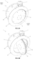
- the circular disc (3) rotates around the rotation axle (4) for alternating between a closed position (shown in Fig. 2A ) and an open position (shown in Fig. 2B ).
- the disc (3) In the closed position, the disc (3) is contained in the plane delimiting the outer end (21) of the body (2), such that the circular edge of the disc (3) abuts against the circular edge of the outer end (21) of the cylindrical body (2) for creating an airtight seal.
- the disc (3) In the open position, the disc (3) is in parallel with the longitudinal axis (A) of the body (2), and therefore air can flow through the valve (1).
- a motor (7) attached to the external surface of the cylindrical body (2) actuates the rotation axle (4) for causing the disc (3) to move between the closed and open positions.
- the disc (3) is made by two layers: an outer fire-resistant layer (31) and an inner pressure-resistant layer (32, 33).
- Fig. 3 shows these layers (31, 32, 33) in greater detail.
- the inner pressure-resistant layer (32, 33) comprises an intermediate metal base plate (32) and an inner rigid frame (33) attached thereto.
- the frame (33) is formed by a number of metal bars having an essentially square cross-section and rigidly connected ones to the other forming a single unit.
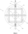
- the frame (33) comprises two pairs of parallel bars connected to form a square. Centred in this square, and in parallel thereto, a cross formed by two bars forming a 90° angle are provided.
- the bars making up the frame (33) are joined ones to the others at each intersection by any suitable means such as, e.g. welding.
- the frame (33) is attached to the intermediate base plate (32) by any suitable means such as e.g. screwing or welding.
- a bar (331) of the two bars making up the cross of the inner rigid frame (33) makes up a central portion of the rotation axle (4).
- Bar (331), oriented in a vertical direction in the figures, has bushings (B) at the ends for connecting said bar (331) having a square cross section with the cylindrical end portions (41) of the rotation axle (4).
- the bushings (B) have a pair of holes for attachment to the bar (331) and to the cylindrical end portions (41) by means of screws. These circular end portions (41) pass through respective holes in the cylindrical body (2).
- the axle (41) therefore cannot be displaced either inwards or outwards when subjected to the pressure wave, therefore providing the valve (1) with a suitable resistance.
- the outer fire-resistant layer (31) is a 60 mm thick plate made of a fire-resistant material.
- the fire-resistant layer (31) is connected to the base plate (32) of the pressure-resistant layer (33) by means of a plurality of screws.
- the outer ends of the screws, normally the head, are protected by means of a fire-resistant silicone material.
- the periphery of the disc (3) comprises an intumescent seal ring.
- This ring ensures an airtight closure even in case temperatures rise over 190oC, in which case the seal ring expands.
- an adjustment flange (6) made of a suitable fire-resistant material is provided for covering said front side.
- the upper end portion (41) of the axle is actuated by a motor (7). Therefore, in the event of an emergency, the valve (1) of the invention is opened and the respective fan activated.
Landscapes
- Engineering & Computer Science (AREA)
- General Engineering & Computer Science (AREA)
- Mechanical Engineering (AREA)
- Taps Or Cocks (AREA)
- Lift Valve (AREA)
Abstract
Description
- The present invention belongs to the field of transport infrastructure, and more particularly to fire protection inside railway tunnels.
- The object of the present invention is a fire-resistant valve specifically designed to withstand the "piston effect" in railway tunnels, that is, the pressure wave caused by a high-speed train entering a tunnel.
- In any transport infrastructure, tunnels are specially critic from the point of view of security, since it is difficult for people to escape an emergency. For that reason, nowadays a secondary, emergency tunnels is usually provided in parallel to the main tunnel. The emergency tunnel may be a dedicated tunnel, or else a tunnel for trains running in the opposite direction. In any case, the main tunnel and the emergency tunnel are connected by corridors provided at regular intervals. Each corridor has a door to the main tunnel and a door to the emergency tunnel. In case of emergency, people can therefore escape the main tunnel by opening a first door to one of the corridors, passing through the corridor, and then opening a second door to the emergency tunnel.
- However, when the emergency is a fire, once the first and second doors are opened by people escaping through the corridor, smoke from the main tunnel may also pass through the corridor towards the emergency tunnel. To prevent this from happening, it is known to provide at least one fan between the emergency tunnel and the corridor, and/or between the corridor and the main tunnel. Optionally, a silencer may also be provided between the fans and the corridor. These fans create an airflow through the corridor from the emergency tunnel towards the main tunnel, thereby preventing smoke from the main tunnel from entering into the emergency tunnel.
- During normal use, when there is no emergency, the fans mentioned above are inactive. However, they provide a path for foul air inside the main tunnel towards the emergency tunnel.
- Therefore, to maintain the corridor fully separated from the main tunnel and the emergency tunnel during normal use of the tunnel, a fire-resistant valve adjacent each of the fans is provided for separating the fan from the corresponding tunnel. The valve is fire-resistant, since it must withstand the high temperature inside the tunnel when there is a fire.
- During normal use, when the fans are inactive, the fire-resistant valve is closed. No air can pass through the corridor from the main tunnel towards the emergency tunnel. When an emergency occurs, the fire-resistant valve automatically opens and, at the same time, the fan starts. An airflow passes through the corridor from the emergency tunnel towards the main tunnel, preventing smoke from entering the emergency tunnel along with the people escaping the fire.
- While this security system is useful in normal tunnels, a problem arises when installed in high-speed train tunnels. High-speed trains passing through the main tunnel cause a pressure wave moving through the tunnel from the entrance towards the exit. This is known as the "piston effect". The pressure wave caused by the piston effect could be as high as 10.000 Pa. This pressure wave breaks conventional fire-resistant valves.
- To solve this problem, an additional, high-pressure valve can be added over the conventional fire-resistant valve. In this manner, two consecutive valves are provided: a fire-resistant valve, and a pressure-resistant valve. While this solution duly solves the problem, it requires twice the space of a single valve.
- The inventors of the present invention have developed a novel fire-resistant valve that can also withstand pressure waves of the type caused by the piston effect in high-speed train tunnels. This valve has a closure disc having two layers, i.e. an outer fire-resistant layer and an inner pressure-resistant layer, thereby solving the problem in a much more compact manner.
- The present invention is therefore directed to a fire-resistant valve for high-speed railway tunnels. The valve comprises a cylindrical main body and a circular disc, where the disc rotates around a radial axle contained in an end plane of the main body, the end plane being perpendicular to an axis of the cylindrical main body. With this configuration, the circular disc alternates between a closed position and an open position. In the closed position, the circular disc is contained in the end plane and abuts against a circular end edge of the cylindrical body, thereby creating an airtight seal that prevents smoke from passing through when the fan is inactive in the absence of an emergency. In the open position, the circular disc is contained in a plane in parallel to the axis of the cylindrical main body, thereby allowing air to flow through the valve when the fan is started during an emergency.
- The features disclosed above form part of the state of the art, since they correspond to a conventional fire-resistant valve of the type commonly employed in this field. However, unlike conventional fire-resistant valves, the disc of the present fire-resistant valve comprises two distinct layers: an outer fire-resistant layer configured for withstanding heat from a fire, coupled to an inner pressure-resistant resistant layer configured for withstanding a pressure wave caused by a high-speed train entering a tunnel. As mentioned above, the pressure caused by a high-speed train could be as high as 10.000 Pa. The inner pressure-resistant layer thereby provides support to the outer fire-resistant layer, ensuring that the valve as a whole withstands the pressure.
- The pressure-resistant layer could be configured in a number of different manners provided it can withstand the above-mentioned pressure for providing support to the fire-resistant outer layer. In a particularly preferred embodiment of the invention, the inner pressure-resistant layer comprises an intermediate metal base plate and an inner rigid frame connected to said intermediate base plate. The intermediate base plate is rigid enough for providing a flat support surface for the outer fire-resistant layer, but it is the inner rigid frame that truly withstands the pressure.
- Thereto, preferably the inner rigid frame comprises a plurality of metal bars having an essentially square cross-section rigidly connected to an inner face of the base plate. The dimensions and thickness of the metal bars are selected to ensure that the frame does withstand the required pressure.
- In a particularly preferred embodiment, the radial axle comprises a central portion and respective end portions. The central portion comprises a radial metal bar of the inner rigid frame, and the end portions are connected to the radial metal bar by means of bushings. The bushings therefore connect the radial metal bar of the frame, having an essentially square cross-section, with the cylindrical end portions of the axle. These end portions, in turn, pass through holes of the main body. This configuration provides the rigid frame with a firm support against the external surface of the main body, thereby ensuring that the disc as a whole is not displaced by the pressure wave.
- The inner rigid frame could have any configuration provided it withstands the inward force caused by the pressure wave inside the tunnel. In a particularly preferred embodiment of the invention, the inner rigid frame is shaped as a square superposed by a cross. More particularly, the square of the inner rigid frame comprises four bars making a square, the cross of the inner rigid frame comprises two bars making up a cross, where each of the bars making up the cross are parallel to a respective pair of bars making up the square. Finally, one of the bars making up the cross is the central portion of the radial axle.
- Preferably, the fire-resistant layer is between 40 mm and 80 mm thick. The fire-resistant layer could be made of any material suitable for withstanding fire temperatures. Fire-resistant materials can comprise intumescent materials. Examples of fire-resistant materials are ceramic materials, calcium silicate, magnesium oxide, alumina oxide, silica oxide, or the like.
- In principle, the fire-resistant layer can be coupled with the pressure-resistant layer in any suitable manner. For example, according to a particularly preferred embodiment of the invention, the fire-resistant layer is screwed to the pressure-resistant layer, and more preferably to the intermediate base plate of the pressure-resistant layer. The screws used to screw the fire-resistant layer to the pressure-resistant layer are preferably covered with a fire-resistant silicone. Further, the valve preferably further comprises a fire-resistant adjustment flange coupled to a front side of the end edge of the cylindrical body. The front side of the valve as a whole is therefore suitably protected against high temperatures.
- In the valve of the invention, an airtight fit is needed between the circular disc and the end edge of the cylindrical body. Thereto, an intumescent seal ring is provided at the periphery of the fire-resistant layer of the circular disc for ensuring an airtight abutment of said circular disc against said end edge of the cylindrical body.
- In still a further preferred embodiment of the invention, the valve comprises a motor configured to cause the circular disc to move between the open position and the closed position.
-
-
Fig. 1 shows a schematic view of the tunnel system where the valve of the invention is normally employed. -
Figs. 2A and 2B show a perspective view of the fire-resistant valve according to the invention respectively in a closed position and in an open position. -
Fig. 3 shows an exploded view of the fire-resistant valve according to the invention. -
Fig. 4 shows a detailed view of the upper portion of the valve according to the invention. -
Fig. 5 shows a view of the pressure-resistant portion of the circular disc of the valve according to the invention. - A particularly preferred embodiment of the invention is disclosed in connection with the attached figures.
-
Figs. 1 schematically shows a prior art emergency system for railway tunnels. There is a main tunnel and an emergency tunnel connected by a corridor (again, note that the emergency tunnel may be a tunnel for trains running in an opposite direction with respect to those running through the main tunnel). Two sets of devices are installed at the wall separating each tunnel from the corridor. A first set includes a protection valve (P) immediately at the wall side, then an emergency fan (F), and then a silencer (S). A second set comprises a protection valve (P) at the wall side, then an overpressure damper (D). -
Fig. 2-5 show several views of the valve (1) of the invention. The valve comprises a cylindrical body (2) delimited at each end (21, 22) by two planes in perpendicular to a longitudinal axis (A) of said body (2). An inner end (22) of the body (2) is facing the corridor (inner side), while an outer end (21) of the body (2) is facing the tunnel (outer side). The cylindrical body (2) comprises a cylindrical protection cover (8) attached thereto. - A circular disc (3) is rotatably coupled to the cylindrical body (2) at the outer end. In particular, the disc (3) is fixed to a radial rotation axle (4) contained in the end plane of the body at the outer end (21) and having ends coupled to opposite portions of the body (2). The circular disc (3) rotates around the rotation axle (4) for alternating between a closed position (shown in
Fig. 2A ) and an open position (shown inFig. 2B ). In the closed position, the disc (3) is contained in the plane delimiting the outer end (21) of the body (2), such that the circular edge of the disc (3) abuts against the circular edge of the outer end (21) of the cylindrical body (2) for creating an airtight seal. In the open position, the disc (3) is in parallel with the longitudinal axis (A) of the body (2), and therefore air can flow through the valve (1). A motor (7) attached to the external surface of the cylindrical body (2) actuates the rotation axle (4) for causing the disc (3) to move between the closed and open positions. - According to the present invention, the disc (3) is made by two layers: an outer fire-resistant layer (31) and an inner pressure-resistant layer (32, 33).
Fig. 3 shows these layers (31, 32, 33) in greater detail. - The inner pressure-resistant layer (32, 33) comprises an intermediate metal base plate (32) and an inner rigid frame (33) attached thereto. As shown in
Fig. 5 , the frame (33) is formed by a number of metal bars having an essentially square cross-section and rigidly connected ones to the other forming a single unit. In this particular embodiment, the frame (33) comprises two pairs of parallel bars connected to form a square. Centred in this square, and in parallel thereto, a cross formed by two bars forming a 90° angle are provided. The bars making up the frame (33) are joined ones to the others at each intersection by any suitable means such as, e.g. welding. The frame (33) is attached to the intermediate base plate (32) by any suitable means such as e.g. screwing or welding. - A bar (331) of the two bars making up the cross of the inner rigid frame (33) makes up a central portion of the rotation axle (4). Bar (331), oriented in a vertical direction in the figures, has bushings (B) at the ends for connecting said bar (331) having a square cross section with the cylindrical end portions (41) of the rotation axle (4). The bushings (B) have a pair of holes for attachment to the bar (331) and to the cylindrical end portions (41) by means of screws. These circular end portions (41) pass through respective holes in the cylindrical body (2). The axle (41) therefore cannot be displaced either inwards or outwards when subjected to the pressure wave, therefore providing the valve (1) with a suitable resistance.
- The outer fire-resistant layer (31) is a 60 mm thick plate made of a fire-resistant material. The fire-resistant layer (31) is connected to the base plate (32) of the pressure-resistant layer (33) by means of a plurality of screws. The outer ends of the screws, normally the head, are protected by means of a fire-resistant silicone material.
- To ensure a suitable airtight abutment of the disc (3) against the end edge (21) of the body (2) when the valve (1) is in the closed position, the periphery of the disc (3) comprises an intumescent seal ring. This ring ensures an airtight closure even in case temperatures rise over 190ºC, in which case the seal ring expands. In addition, to protect the front side of the flange making up the outer end of the body (2), an adjustment flange (6) made of a suitable fire-resistant material is provided for covering said front side.
- As shown in
Fig. 4 , the upper end portion (41) of the axle is actuated by a motor (7). Therefore, in the event of an emergency, the valve (1) of the invention is opened and the respective fan activated.
Claims (13)
- Fire-resistant valve (1) for high-speed railway tunnels, comprising a cylindrical main body (2) and a circular disc (3), where the disc (3) rotates around a radial axle (4) contained in an end plane of the main body (2), where the end plane is perpendicular to an axis (A) of the cylindrical main body (2), such that the circular disc (3) alternates between a closed position where it is contained in said end plane and abuts against a circular end edge (21) of the cylindrical body (2), and an open position where it is contained in a plane in parallel to the axis (A) of the cylindrical main body (2),
characterized in that the disc (3) comprises an outer fire-resistant layer (31) configured for withstanding heat from a fire, coupled to an inner pressure-resistant resistant layer (32, 33) configured for withstanding a pressure wave caused by a high-speed train entering a tunnel. - Fire-resistant valve (1) according to claim 1, where the inner pressure-resistant layer (31) comprises an intermediate metal base plate (32) and an inner rigid frame (33) connected to said intermediate base plate (32).
- Fire-resistant valve (1) according to claim 2, where the inner rigid frame (33) comprises a plurality of metal bars having an essentially square cross-section rigidly connected to an inner face of the base plate (32).
- Fire-resistant valve (1) according to claim 3, where the radial axle (4) comprises a central portion and respective end portions (41), the central portion comprising a radial metal bar (331) of the inner rigid frame (33), and the end portions (41) being connected to the radial metal bar (331) by means of bushings (B).
- Fire-resistant valve (1) according to any of claims 3-4, where the inner rigid frame (33) is shaped as a square superposed by a cross.
- Fire-resistant valve (1) according to claim 5, where the square of the inner rigid frame (33) comprises four bars making a square, the cross of the inner rigid frame (33) comprises two bars making up a cross, where each of the bars making up the cross are parallel to a respective pair of bars making up the square, and where bar (331) of the two bars making up the cross is the central portion of the radial axle (4).
- Fire-resistant valve (1) according to any of the previous claims, where the fire-resistant layer (31) is screwed to the pressure-resistant layer (32, 33).
- Fire-resistant valve (1) according to claim 7, where the fire-resistant layer (31) is screwed to the intermediate base plate (32) of the pressure-resistant layer (32, 33).
- Fire-resistant valve (1) according to any of claims 7-8, where the screws used to screw the fire-resistant layer (31) to the pressure-resistant layer (32, 33) are covered with a fire-resistant silicone.
- Fire-resistant valve (1) according to any of the previous claims, where the fire-resistant layer (31) is between 40 mm and 80 mm thick.
- Fire-resistant valve (1) according to any of the previous claims, further comprising a fire-resistant adjustment flange (6) coupled to a front side of the end edge (21) of the cylindrical body (2).
- Fire-resistant valve (1) according to any of the previous claims, further comprising an intumescent seal ring provided at the periphery of the fire-resistant layer (31) of the circular disc (3) for ensuring an airtight abutment of said circular disc (3) against the circular end edge (21) of the cylindrical body (2).
- Fire-resistant valve (1) according to any of the previous claims, further comprising a motor (7) configured to cause the circular disc (3) move between the open position and the closed position.
Priority Applications (2)
| Application Number | Priority Date | Filing Date | Title |
|---|---|---|---|
| ES23382993T ES3055050T3 (en) | 2023-09-29 | 2023-09-29 | Fire-resistant valve for high-speed railway tunnels |
| EP23382993.6A EP4530505B1 (en) | 2023-09-29 | 2023-09-29 | Fire-resistant valve for high-speed railway tunnels |
Applications Claiming Priority (1)
| Application Number | Priority Date | Filing Date | Title |
|---|---|---|---|
| EP23382993.6A EP4530505B1 (en) | 2023-09-29 | 2023-09-29 | Fire-resistant valve for high-speed railway tunnels |
Publications (2)
| Publication Number | Publication Date |
|---|---|
| EP4530505A1 true EP4530505A1 (en) | 2025-04-02 |
| EP4530505B1 EP4530505B1 (en) | 2025-10-22 |
Family
ID=88237948
Family Applications (1)
| Application Number | Title | Priority Date | Filing Date |
|---|---|---|---|
| EP23382993.6A Active EP4530505B1 (en) | 2023-09-29 | 2023-09-29 | Fire-resistant valve for high-speed railway tunnels |
Country Status (2)
| Country | Link |
|---|---|
| EP (1) | EP4530505B1 (en) |
| ES (1) | ES3055050T3 (en) |
Citations (6)
| Publication number | Priority date | Publication date | Assignee | Title |
|---|---|---|---|---|
| US4559867A (en) * | 1984-06-29 | 1985-12-24 | Philips Industrial Components, Inc. | Round damper and fusible link therefor |
| US4648418A (en) * | 1986-03-05 | 1987-03-10 | Keystone International, Inc. | Fireproof valve assembly and valve element for use therein |
| US20180185680A1 (en) * | 2016-12-28 | 2018-07-05 | Nederman Holding Ab | Back pressure flap valve arrangement and the use thereof |
| CN110296221A (en) * | 2019-08-05 | 2019-10-01 | 周天桥 | A kind of lever soft sealing butterfly valve |
| CN114838143A (en) * | 2022-04-06 | 2022-08-02 | 五洲阀门股份有限公司 | High-temperature-resistant butterfly valve |
| CN115370814A (en) * | 2022-09-23 | 2022-11-22 | 凯喜姆科技集团温州擒工冶金阀门有限公司 | Heat-resisting three-eccentric center butterfly valve |
-
2023
- 2023-09-29 EP EP23382993.6A patent/EP4530505B1/en active Active
- 2023-09-29 ES ES23382993T patent/ES3055050T3/en active Active
Patent Citations (6)
| Publication number | Priority date | Publication date | Assignee | Title |
|---|---|---|---|---|
| US4559867A (en) * | 1984-06-29 | 1985-12-24 | Philips Industrial Components, Inc. | Round damper and fusible link therefor |
| US4648418A (en) * | 1986-03-05 | 1987-03-10 | Keystone International, Inc. | Fireproof valve assembly and valve element for use therein |
| US20180185680A1 (en) * | 2016-12-28 | 2018-07-05 | Nederman Holding Ab | Back pressure flap valve arrangement and the use thereof |
| CN110296221A (en) * | 2019-08-05 | 2019-10-01 | 周天桥 | A kind of lever soft sealing butterfly valve |
| CN114838143A (en) * | 2022-04-06 | 2022-08-02 | 五洲阀门股份有限公司 | High-temperature-resistant butterfly valve |
| CN115370814A (en) * | 2022-09-23 | 2022-11-22 | 凯喜姆科技集团温州擒工冶金阀门有限公司 | Heat-resisting three-eccentric center butterfly valve |
Also Published As
| Publication number | Publication date |
|---|---|
| EP4530505B1 (en) | 2025-10-22 |
| ES3055050T3 (en) | 2026-02-09 |
Similar Documents
| Publication | Publication Date | Title |
|---|---|---|
| US6702230B2 (en) | Ballistic resistant flight deck door assembly having ventilation feature | |
| EP0305340B1 (en) | A security vestibule entry for controlled access to banks and the like | |
| US6925756B2 (en) | Apparatus for controlling the ingress and egress to and from an operator's compartment | |
| US20040211150A1 (en) | Method and apparatus for detecting smoke and smothering a fire | |
| US9187918B2 (en) | High rise building with a stairwell and a intake air shaft | |
| KR102475984B1 (en) | Evacuation Passage Structure for Tunnel | |
| WO2020056276A9 (en) | Fragment-, overpressure-, radiation-, and toxic-resistant emergency safety shelter | |
| KR102257464B1 (en) | Emergency evacuation elevator having double hall door of airtight type capable of fireproof performance over 3 hours | |
| EP4530505B1 (en) | Fire-resistant valve for high-speed railway tunnels | |
| US7331401B2 (en) | Method and apparatus for fighting a fire in an enclosed space in an aircraft | |
| AU2025271529A1 (en) | Hatch Construction | |
| US5495894A (en) | Fire protection filter | |
| KR102609387B1 (en) | The Fire Escape Apparatus Assembly for Apartment House | |
| CN114562191A (en) | Composite fire door with bidirectional shock wave resisting function | |
| EP3960683B1 (en) | Elevator control cabinet, elevator system, conveyor system control cabinet and conveyor system | |
| CN111255288B (en) | Fire refuge safety room for high-rise building | |
| KR101102451B1 (en) | Explosion proof valve | |
| UA125299C2 (en) | NUCLEAR POWER PLANT CONTROLS DISTRIBUTION SYSTEM | |
| JP2003120141A (en) | Fire door | |
| KR102098392B1 (en) | Fire evacuation device | |
| US5560165A (en) | Joint between a landing door and wall structures | |
| CN205502646U (en) | X -radiation shielding building | |
| US2350981A (en) | Door for bomb and gas resisting shelters, buildings, and the like | |
| US234895A (en) | Means for tightly closing doorways | |
| CN210948794U (en) | Tunnel fire door and tunnel fire system |
Legal Events
| Date | Code | Title | Description |
|---|---|---|---|
| PUAI | Public reference made under article 153(3) epc to a published international application that has entered the european phase |
Free format text: ORIGINAL CODE: 0009012 |
|
| STAA | Information on the status of an ep patent application or granted ep patent |
Free format text: STATUS: THE APPLICATION HAS BEEN PUBLISHED |
|
| AK | Designated contracting states |
Kind code of ref document: A1 Designated state(s): AL AT BE BG CH CY CZ DE DK EE ES FI FR GB GR HR HU IE IS IT LI LT LU LV MC ME MK MT NL NO PL PT RO RS SE SI SK SM TR |
|
| STAA | Information on the status of an ep patent application or granted ep patent |
Free format text: STATUS: REQUEST FOR EXAMINATION WAS MADE |
|
| GRAP | Despatch of communication of intention to grant a patent |
Free format text: ORIGINAL CODE: EPIDOSNIGR1 |
|
| STAA | Information on the status of an ep patent application or granted ep patent |
Free format text: STATUS: GRANT OF PATENT IS INTENDED |
|
| 17P | Request for examination filed |
Effective date: 20250611 |
|
| INTG | Intention to grant announced |
Effective date: 20250707 |
|
| GRAS | Grant fee paid |
Free format text: ORIGINAL CODE: EPIDOSNIGR3 |
|
| GRAA | (expected) grant |
Free format text: ORIGINAL CODE: 0009210 |
|
| STAA | Information on the status of an ep patent application or granted ep patent |
Free format text: STATUS: THE PATENT HAS BEEN GRANTED |
|
| AK | Designated contracting states |
Kind code of ref document: B1 Designated state(s): AL AT BE BG CH CY CZ DE DK EE ES FI FR GB GR HR HU IE IS IT LI LT LU LV MC ME MK MT NL NO PL PT RO RS SE SI SK SM TR |
|
| REG | Reference to a national code |
Ref country code: CH Ref legal event code: F10 Free format text: ST27 STATUS EVENT CODE: U-0-0-F10-F00 (AS PROVIDED BY THE NATIONAL OFFICE) Effective date: 20251022 Ref country code: GB Ref legal event code: FG4D |
|
| REG | Reference to a national code |
Ref country code: DE Ref legal event code: R096 Ref document number: 602023007766 Country of ref document: DE |
|
| REG | Reference to a national code |
Ref country code: IE Ref legal event code: FG4D |
|
| REG | Reference to a national code |
Ref country code: ES Ref legal event code: FG2A Ref document number: 3055050 Country of ref document: ES Kind code of ref document: T3 Effective date: 20260209 |
|
| REG | Reference to a national code |
Ref country code: NL Ref legal event code: MP Effective date: 20251022 |
|
| PG25 | Lapsed in a contracting state [announced via postgrant information from national office to epo] |
Ref country code: NL Free format text: LAPSE BECAUSE OF FAILURE TO SUBMIT A TRANSLATION OF THE DESCRIPTION OR TO PAY THE FEE WITHIN THE PRESCRIBED TIME-LIMIT Effective date: 20251022 |
|
| REG | Reference to a national code |
Ref country code: LT Ref legal event code: MG9D |
|
| PG25 | Lapsed in a contracting state [announced via postgrant information from national office to epo] |
Ref country code: NO Free format text: LAPSE BECAUSE OF FAILURE TO SUBMIT A TRANSLATION OF THE DESCRIPTION OR TO PAY THE FEE WITHIN THE PRESCRIBED TIME-LIMIT Effective date: 20260122 |
|
| PG25 | Lapsed in a contracting state [announced via postgrant information from national office to epo] |
Ref country code: HR Free format text: LAPSE BECAUSE OF FAILURE TO SUBMIT A TRANSLATION OF THE DESCRIPTION OR TO PAY THE FEE WITHIN THE PRESCRIBED TIME-LIMIT Effective date: 20251022 Ref country code: AT Free format text: LAPSE BECAUSE OF FAILURE TO SUBMIT A TRANSLATION OF THE DESCRIPTION OR TO PAY THE FEE WITHIN THE PRESCRIBED TIME-LIMIT Effective date: 20251022 Ref country code: FI Free format text: LAPSE BECAUSE OF FAILURE TO SUBMIT A TRANSLATION OF THE DESCRIPTION OR TO PAY THE FEE WITHIN THE PRESCRIBED TIME-LIMIT Effective date: 20251022 |
|
| REG | Reference to a national code |
Ref country code: AT Ref legal event code: MK05 Ref document number: 1849382 Country of ref document: AT Kind code of ref document: T Effective date: 20251022 |
|
| PG25 | Lapsed in a contracting state [announced via postgrant information from national office to epo] |
Ref country code: RS Free format text: LAPSE BECAUSE OF FAILURE TO SUBMIT A TRANSLATION OF THE DESCRIPTION OR TO PAY THE FEE WITHIN THE PRESCRIBED TIME-LIMIT Effective date: 20260122 |
|
| PG25 | Lapsed in a contracting state [announced via postgrant information from national office to epo] |
Ref country code: IS Free format text: LAPSE BECAUSE OF FAILURE TO SUBMIT A TRANSLATION OF THE DESCRIPTION OR TO PAY THE FEE WITHIN THE PRESCRIBED TIME-LIMIT Effective date: 20260222 |
|
| PG25 | Lapsed in a contracting state [announced via postgrant information from national office to epo] |
Ref country code: PT Free format text: LAPSE BECAUSE OF FAILURE TO SUBMIT A TRANSLATION OF THE DESCRIPTION OR TO PAY THE FEE WITHIN THE PRESCRIBED TIME-LIMIT Effective date: 20260223 |
|
| PG25 | Lapsed in a contracting state [announced via postgrant information from national office to epo] |
Ref country code: LV Free format text: LAPSE BECAUSE OF FAILURE TO SUBMIT A TRANSLATION OF THE DESCRIPTION OR TO PAY THE FEE WITHIN THE PRESCRIBED TIME-LIMIT Effective date: 20251022 |
|
| PG25 | Lapsed in a contracting state [announced via postgrant information from national office to epo] |
Ref country code: BG Free format text: LAPSE BECAUSE OF FAILURE TO SUBMIT A TRANSLATION OF THE DESCRIPTION OR TO PAY THE FEE WITHIN THE PRESCRIBED TIME-LIMIT Effective date: 20251022 |
|
| PG25 | Lapsed in a contracting state [announced via postgrant information from national office to epo] |
Ref country code: LT Free format text: LAPSE BECAUSE OF FAILURE TO SUBMIT A TRANSLATION OF THE DESCRIPTION OR TO PAY THE FEE WITHIN THE PRESCRIBED TIME-LIMIT Effective date: 20251022 |
|
| PG25 | Lapsed in a contracting state [announced via postgrant information from national office to epo] |
Ref country code: SM Free format text: LAPSE BECAUSE OF FAILURE TO SUBMIT A TRANSLATION OF THE DESCRIPTION OR TO PAY THE FEE WITHIN THE PRESCRIBED TIME-LIMIT Effective date: 20251022 |
|
| PG25 | Lapsed in a contracting state [announced via postgrant information from national office to epo] |
Ref country code: DK Free format text: LAPSE BECAUSE OF FAILURE TO SUBMIT A TRANSLATION OF THE DESCRIPTION OR TO PAY THE FEE WITHIN THE PRESCRIBED TIME-LIMIT Effective date: 20251022 |
|
| PG25 | Lapsed in a contracting state [announced via postgrant information from national office to epo] |
Ref country code: EE Free format text: LAPSE BECAUSE OF FAILURE TO SUBMIT A TRANSLATION OF THE DESCRIPTION OR TO PAY THE FEE WITHIN THE PRESCRIBED TIME-LIMIT Effective date: 20251022 |
|
| PG25 | Lapsed in a contracting state [announced via postgrant information from national office to epo] |
Ref country code: CZ Free format text: LAPSE BECAUSE OF FAILURE TO SUBMIT A TRANSLATION OF THE DESCRIPTION OR TO PAY THE FEE WITHIN THE PRESCRIBED TIME-LIMIT Effective date: 20251022 |
|
| PG25 | Lapsed in a contracting state [announced via postgrant information from national office to epo] |
Ref country code: SK Free format text: LAPSE BECAUSE OF FAILURE TO SUBMIT A TRANSLATION OF THE DESCRIPTION OR TO PAY THE FEE WITHIN THE PRESCRIBED TIME-LIMIT Effective date: 20251022 |
|
| PG25 | Lapsed in a contracting state [announced via postgrant information from national office to epo] |
Ref country code: SE Free format text: LAPSE BECAUSE OF FAILURE TO SUBMIT A TRANSLATION OF THE DESCRIPTION OR TO PAY THE FEE WITHIN THE PRESCRIBED TIME-LIMIT Effective date: 20251022 |