EP4530454A1 - Steuersystem und -verfahren für ein hybridelektrisches flugzeugantriebssystem - Google Patents
Steuersystem und -verfahren für ein hybridelektrisches flugzeugantriebssystem Download PDFInfo
- Publication number
- EP4530454A1 EP4530454A1 EP24203010.4A EP24203010A EP4530454A1 EP 4530454 A1 EP4530454 A1 EP 4530454A1 EP 24203010 A EP24203010 A EP 24203010A EP 4530454 A1 EP4530454 A1 EP 4530454A1
- Authority
- EP
- European Patent Office
- Prior art keywords
- electric motor
- gas turbine
- turbine engine
- motive force
- engine
- Prior art date
- Legal status (The legal status is an assumption and is not a legal conclusion. Google has not performed a legal analysis and makes no representation as to the accuracy of the status listed.)
- Pending
Links
Images

Classifications
-
- F—MECHANICAL ENGINEERING; LIGHTING; HEATING; WEAPONS; BLASTING
- F02—COMBUSTION ENGINES; HOT-GAS OR COMBUSTION-PRODUCT ENGINE PLANTS
- F02K—JET-PROPULSION PLANTS
- F02K5/00—Plants including an engine, other than a gas turbine, driving a compressor or a ducted fan
-
- B—PERFORMING OPERATIONS; TRANSPORTING
- B64—AIRCRAFT; AVIATION; COSMONAUTICS
- B64D—EQUIPMENT FOR FITTING IN OR TO AIRCRAFT; FLIGHT SUITS; PARACHUTES; ARRANGEMENT OR MOUNTING OF POWER PLANTS OR PROPULSION TRANSMISSIONS IN AIRCRAFT
- B64D27/00—Arrangement or mounting of power plants in aircraft; Aircraft characterised by the type or position of power plants
- B64D27/02—Aircraft characterised by the type or position of power plants
- B64D27/24—Aircraft characterised by the type or position of power plants using steam or spring force
-
- B—PERFORMING OPERATIONS; TRANSPORTING
- B64—AIRCRAFT; AVIATION; COSMONAUTICS
- B64D—EQUIPMENT FOR FITTING IN OR TO AIRCRAFT; FLIGHT SUITS; PARACHUTES; ARRANGEMENT OR MOUNTING OF POWER PLANTS OR PROPULSION TRANSMISSIONS IN AIRCRAFT
- B64D27/00—Arrangement or mounting of power plants in aircraft; Aircraft characterised by the type or position of power plants
- B64D27/02—Aircraft characterised by the type or position of power plants
- B64D27/30—Aircraft characterised by electric power plants
- B64D27/33—Hybrid electric aircraft
-
- B—PERFORMING OPERATIONS; TRANSPORTING
- B64—AIRCRAFT; AVIATION; COSMONAUTICS
- B64D—EQUIPMENT FOR FITTING IN OR TO AIRCRAFT; FLIGHT SUITS; PARACHUTES; ARRANGEMENT OR MOUNTING OF POWER PLANTS OR PROPULSION TRANSMISSIONS IN AIRCRAFT
- B64D27/00—Arrangement or mounting of power plants in aircraft; Aircraft characterised by the type or position of power plants
- B64D27/02—Aircraft characterised by the type or position of power plants
- B64D27/30—Aircraft characterised by electric power plants
- B64D27/35—Arrangements for on-board electric energy production, distribution, recovery or storage
- B64D27/357—Arrangements for on-board electric energy production, distribution, recovery or storage using batteries
-
- B—PERFORMING OPERATIONS; TRANSPORTING
- B64—AIRCRAFT; AVIATION; COSMONAUTICS
- B64D—EQUIPMENT FOR FITTING IN OR TO AIRCRAFT; FLIGHT SUITS; PARACHUTES; ARRANGEMENT OR MOUNTING OF POWER PLANTS OR PROPULSION TRANSMISSIONS IN AIRCRAFT
- B64D35/00—Transmitting power from power plants to propellers or rotors; Arrangements of transmissions
- B64D35/02—Transmitting power from power plants to propellers or rotors; Arrangements of transmissions specially adapted for specific power plants
- B64D35/021—Transmitting power from power plants to propellers or rotors; Arrangements of transmissions specially adapted for specific power plants for electric power plants
- B64D35/022—Transmitting power from power plants to propellers or rotors; Arrangements of transmissions specially adapted for specific power plants for electric power plants of hybrid-electric type
- B64D35/025—Transmitting power from power plants to propellers or rotors; Arrangements of transmissions specially adapted for specific power plants for electric power plants of hybrid-electric type of parallel type
-
- F—MECHANICAL ENGINEERING; LIGHTING; HEATING; WEAPONS; BLASTING
- F01—MACHINES OR ENGINES IN GENERAL; ENGINE PLANTS IN GENERAL; STEAM ENGINES
- F01D—NON-POSITIVE DISPLACEMENT MACHINES OR ENGINES, e.g. STEAM TURBINES
- F01D15/00—Adaptations of machines or engines for special use; Combinations of engines with devices driven thereby
- F01D15/10—Adaptations for driving, or combinations with, electric generators
-
- F—MECHANICAL ENGINEERING; LIGHTING; HEATING; WEAPONS; BLASTING
- F02—COMBUSTION ENGINES; HOT-GAS OR COMBUSTION-PRODUCT ENGINE PLANTS
- F02C—GAS-TURBINE PLANTS; AIR INTAKES FOR JET-PROPULSION PLANTS; CONTROLLING FUEL SUPPLY IN AIR-BREATHING JET-PROPULSION PLANTS
- F02C3/00—Gas-turbine plants characterised by the use of combustion products as the working fluid
- F02C3/04—Gas-turbine plants characterised by the use of combustion products as the working fluid having a turbine driving a compressor
- F02C3/10—Gas-turbine plants characterised by the use of combustion products as the working fluid having a turbine driving a compressor with another turbine driving an output shaft but not driving the compressor
-
- F—MECHANICAL ENGINEERING; LIGHTING; HEATING; WEAPONS; BLASTING
- F02—COMBUSTION ENGINES; HOT-GAS OR COMBUSTION-PRODUCT ENGINE PLANTS
- F02C—GAS-TURBINE PLANTS; AIR INTAKES FOR JET-PROPULSION PLANTS; CONTROLLING FUEL SUPPLY IN AIR-BREATHING JET-PROPULSION PLANTS
- F02C7/00—Features, components parts, details or accessories, not provided for in, or of interest apart form groups F02C1/00 - F02C6/00; Air intakes for jet-propulsion plants
- F02C7/32—Arrangement, mounting, or driving, of auxiliaries
-
- F—MECHANICAL ENGINEERING; LIGHTING; HEATING; WEAPONS; BLASTING
- F02—COMBUSTION ENGINES; HOT-GAS OR COMBUSTION-PRODUCT ENGINE PLANTS
- F02C—GAS-TURBINE PLANTS; AIR INTAKES FOR JET-PROPULSION PLANTS; CONTROLLING FUEL SUPPLY IN AIR-BREATHING JET-PROPULSION PLANTS
- F02C7/00—Features, components parts, details or accessories, not provided for in, or of interest apart form groups F02C1/00 - F02C6/00; Air intakes for jet-propulsion plants
- F02C7/36—Power transmission arrangements between the different shafts of the gas turbine plant, or between the gas-turbine plant and the power user
-
- F—MECHANICAL ENGINEERING; LIGHTING; HEATING; WEAPONS; BLASTING
- F02—COMBUSTION ENGINES; HOT-GAS OR COMBUSTION-PRODUCT ENGINE PLANTS
- F02C—GAS-TURBINE PLANTS; AIR INTAKES FOR JET-PROPULSION PLANTS; CONTROLLING FUEL SUPPLY IN AIR-BREATHING JET-PROPULSION PLANTS
- F02C9/00—Controlling gas-turbine plants; Controlling fuel supply in air- breathing jet-propulsion plants
- F02C9/48—Control of fuel supply conjointly with another control of the plant
- F02C9/56—Control of fuel supply conjointly with another control of the plant with power transmission control
-
- B—PERFORMING OPERATIONS; TRANSPORTING
- B64—AIRCRAFT; AVIATION; COSMONAUTICS
- B64D—EQUIPMENT FOR FITTING IN OR TO AIRCRAFT; FLIGHT SUITS; PARACHUTES; ARRANGEMENT OR MOUNTING OF POWER PLANTS OR PROPULSION TRANSMISSIONS IN AIRCRAFT
- B64D27/00—Arrangement or mounting of power plants in aircraft; Aircraft characterised by the type or position of power plants
- B64D27/02—Aircraft characterised by the type or position of power plants
- B64D27/026—Aircraft characterised by the type or position of power plants comprising different types of power plants, e.g. combination of a piston engine and a gas-turbine
-
- F—MECHANICAL ENGINEERING; LIGHTING; HEATING; WEAPONS; BLASTING
- F05—INDEXING SCHEMES RELATING TO ENGINES OR PUMPS IN VARIOUS SUBCLASSES OF CLASSES F01-F04
- F05D—INDEXING SCHEME FOR ASPECTS RELATING TO NON-POSITIVE-DISPLACEMENT MACHINES OR ENGINES, GAS-TURBINES OR JET-PROPULSION PLANTS
- F05D2220/00—Application
- F05D2220/30—Application in turbines
- F05D2220/32—Application in turbines in gas turbines
- F05D2220/323—Application in turbines in gas turbines for aircraft propulsion, e.g. jet engines
-
- F—MECHANICAL ENGINEERING; LIGHTING; HEATING; WEAPONS; BLASTING
- F05—INDEXING SCHEMES RELATING TO ENGINES OR PUMPS IN VARIOUS SUBCLASSES OF CLASSES F01-F04
- F05D—INDEXING SCHEME FOR ASPECTS RELATING TO NON-POSITIVE-DISPLACEMENT MACHINES OR ENGINES, GAS-TURBINES OR JET-PROPULSION PLANTS
- F05D2220/00—Application
- F05D2220/30—Application in turbines
- F05D2220/32—Application in turbines in gas turbines
- F05D2220/329—Application in turbines in gas turbines in helicopters
-
- F—MECHANICAL ENGINEERING; LIGHTING; HEATING; WEAPONS; BLASTING
- F05—INDEXING SCHEMES RELATING TO ENGINES OR PUMPS IN VARIOUS SUBCLASSES OF CLASSES F01-F04
- F05D—INDEXING SCHEME FOR ASPECTS RELATING TO NON-POSITIVE-DISPLACEMENT MACHINES OR ENGINES, GAS-TURBINES OR JET-PROPULSION PLANTS
- F05D2220/00—Application
- F05D2220/70—Application in combination with
- F05D2220/76—Application in combination with an electrical generator
-
- F—MECHANICAL ENGINEERING; LIGHTING; HEATING; WEAPONS; BLASTING
- F05—INDEXING SCHEMES RELATING TO ENGINES OR PUMPS IN VARIOUS SUBCLASSES OF CLASSES F01-F04
- F05D—INDEXING SCHEME FOR ASPECTS RELATING TO NON-POSITIVE-DISPLACEMENT MACHINES OR ENGINES, GAS-TURBINES OR JET-PROPULSION PLANTS
- F05D2260/00—Function
- F05D2260/40—Transmission of power
- F05D2260/403—Transmission of power through the shape of the drive components
- F05D2260/4031—Transmission of power through the shape of the drive components as in toothed gearing
-
- F—MECHANICAL ENGINEERING; LIGHTING; HEATING; WEAPONS; BLASTING
- F05—INDEXING SCHEMES RELATING TO ENGINES OR PUMPS IN VARIOUS SUBCLASSES OF CLASSES F01-F04
- F05D—INDEXING SCHEME FOR ASPECTS RELATING TO NON-POSITIVE-DISPLACEMENT MACHINES OR ENGINES, GAS-TURBINES OR JET-PROPULSION PLANTS
- F05D2270/00—Control
- F05D2270/01—Purpose of the control system
- F05D2270/04—Purpose of the control system to control acceleration (u)
- F05D2270/044—Purpose of the control system to control acceleration (u) by making it as high as possible
-
- F—MECHANICAL ENGINEERING; LIGHTING; HEATING; WEAPONS; BLASTING
- F05—INDEXING SCHEMES RELATING TO ENGINES OR PUMPS IN VARIOUS SUBCLASSES OF CLASSES F01-F04
- F05D—INDEXING SCHEME FOR ASPECTS RELATING TO NON-POSITIVE-DISPLACEMENT MACHINES OR ENGINES, GAS-TURBINES OR JET-PROPULSION PLANTS
- F05D2270/00—Control
- F05D2270/01—Purpose of the control system
- F05D2270/05—Purpose of the control system to affect the output of the engine
- F05D2270/053—Explicitly mentioned power
-
- F—MECHANICAL ENGINEERING; LIGHTING; HEATING; WEAPONS; BLASTING
- F05—INDEXING SCHEMES RELATING TO ENGINES OR PUMPS IN VARIOUS SUBCLASSES OF CLASSES F01-F04
- F05D—INDEXING SCHEME FOR ASPECTS RELATING TO NON-POSITIVE-DISPLACEMENT MACHINES OR ENGINES, GAS-TURBINES OR JET-PROPULSION PLANTS
- F05D2270/00—Control
- F05D2270/30—Control parameters, e.g. input parameters
- F05D2270/335—Output power or torque
Definitions
- the present disclosure relates to methods and apparatus for control systems and method for a gas turbine engine in general, and to methods and apparatus for control systems and method for a gas turbine engine operating in a low power setting in particular.
- a hybrid-electric propulsion (HEP) system includes a gas turbine engine, an electrical power motive system, a system controller, and a propulsor.
- the gas turbine engine has a free turbine configuration that includes a compressor.
- the electrical power motive system has first and second electric motors and first and second inverters.
- the gas turbine engine is configured to provide motive force to the propulsor.
- the first electric motor is configurable in a drive mode to provide motive force to the propulsor or in generator mode to produce electrical energy.
- the second electric motor is in communication with the compressor.
- the system controller is in communication with the gas turbine engine, the first and second inverters, and a non-transitory memory storing instructions, which instructions when executed cause the system controller to control the second inverter to operate the second electric motor to provide a motive force to the compressor of the gas turbine engine during a low power setting of the gas turbine engine.
- the gas turbine engine and the first electric motor may be disposed in a parallel configuration.
- the HEP system may further include a reduction gear box and in the parallel configuration both the gas turbine engine and the first electric motor are in communication with the reduction gear box.
- the instructions when executed may cause the system controller to control the first inverter to operate the first electric motor in the generator mode when the second inverter is controlled to operate the second electric motor to provide motive force to the compressor of the gas turbine engine.
- the gas turbine engine has a first rate of power increase at the low power setting without the motive force from the second electric motor and has a second rate of power increase at the low power setting with the motive force from the second electric motor, wherein the second rate of power increase may be greater than the first rate of power increase.
- the gas turbine engine has a first rate of power increase limit between an engine acceleration request and an engine response to the request during the low power setting without the motive force from the second electric motor, and a second rate of power increase limit between the engine acceleration request and the engine response to the request during the low power setting with the motive force from the second electric motor, wherein the first rate of power increase limit may be greater than the second rate of power increase limit.
- the HEP system may include an accessory gearbox (AGB) in communication with the compressor of the gas turbine engine and the second electric motor.
- AGB accessory gearbox
- the gas turbine engine may include a high-pressure turbine, a power turbine, and a first shaft connecting the compressor to the high-pressure turbine and the AGB is in communication with the first shaft.
- the gas turbine engine may include a second shaft connected to the power turbine, and the first electric motor is in communication with the second shaft.
- the gas turbine engine has an axial centerline and the high-pressure turbine, a power turbine, the first shaft, and the second shaft may be rotatable about the axial centerline.
- a method of controlling a hybrid-electric propulsion (HEP) system includes a gas turbine engine having a free turbine configuration that includes a compressor, an electrical power motive system having a first and second electric motors, first and second inverters, and a propulsor.
- the second electric motor is in communication with the compressor.
- the method includes: controlling the gas turbine engine to provide motive force to the propulsor; controlling the first electric motor to operate in a first mode providing motive force to the propulsor or to operate in a second mode not providing motive force to the propulsor; controlling the first electric motor to provide motive force to the propulsor or to not provide motive force to the propulsor; and controlling the second electric motor to provide motive force to the compressor of the gas turbine engine during a low power setting of the gas turbine engine.
- the first electric motor in the second mode may operate as an electrical generator producing electrical energy.
- the first electric motor may be controlled to operate in the second mode when the second electric motor is controlled to provide motive force to the compressor of the gas turbine engine during the low power setting of the gas turbine engine, wherein the electrical energy produced by the first electric motor is available for use by the second electric motor.
- the HEP system may include a reduction gear box and the gas turbine engine and the first electric motor may be in communication with the reduction gear box, and may be disposed in a parallel configuration.
- the gas turbine engine has a first rate of power increase during the low power setting without the motive force from the second electric motor and has a second rate of power increase during the low power setting with the motive force from the second electric motor, wherein the second rate of power increase may be greater than the first rate of power increase.
- the gas turbine engine has a first lag between an engine power increase request and an engine response to the power increase request during the low power setting without the motive force from the second electric motor, and a second lag between the engine power increase request and the engine response to the power increase request during the low power setting with the motive force from the second electric motor, wherein the first lag is greater than the second lag.
- the gas turbine engine may include a high-pressure turbine, a power turbine, and a first shaft connecting the compressor to the high-pressure turbine and the AGB is in communication with the first shaft.
- the first electric motor in the second mode may operate as an electrical generator producing electrical energy
- the method may include controlling the first electric motor when operating in the second mode to generate a total amount of electrical energy greater than an amount of electrical energy used by the second electric motor, and a providing a difference in electrical energy between the total amount of electrical energy and the amount of electrical energy used by the second electric motor to an electrical energy storage device.
- the method may include controlling the first electric motor operating in second mode to begin operating in the first mode when a propulsor power increase request is made.
- the method may include providing electrical energy from an electrical energy storage device to both the first inverter and second inverter simultaneously.
- the present disclosure is directed to a hybrid-electric propulsion system ("HEP system 20") and method for powering an aircraft.
- the aircraft may be a fixed-wing aircraft, a rotary-wing aircraft (e.g., a helicopter), a tilt-rotor aircraft, a tilt-wing aircraft, or any other aerial vehicle.
- the aircraft may be a manned aerial vehicle or an unmanned aerial vehicle (UAV, e.g., a drone).
- UAV unmanned aerial vehicle
- present disclosure HEP systems 20 include a gas turbine engine 22, an electrical power motive system 24, and a propulsor 26, and the present disclosure system 20 can be configured in a variety of different embodiments.
- the gas turbine engine 22 may take the form of a turboprop engine, a turboshaft engine, a turbojet engine, a propfan engine, or an open rotor engine, or the like.
- the gas turbine engine 22 may have a "free turbine” configuration.
- the propulsor 26 may be any type of device (e.g., propellers, fan blades, rotor blades for a helicopter, a tilt-rotor aircraft, or a tilt-wing aircraft) that can be rotated to provide motive thrust.
- exemplary embodiments of present disclosure HEP systems 20 are diagrammatically shown in FIGS. 1 and 2 . The present disclosure is not limited to these examples.
- FIG. 1 diagrammatically illustrates an HEP system 20 embodiment that includes a gas turbine engine 22, a reduction gear box (RGB) 28, an accessory gearbox (AGB 30), an electrical power motive system 24, a system controller 32, and a propulsor 26.
- the gas turbine engine 22 includes a compressor 23, a combustor 25, and a turbine 27.
- the gas turbine engine is shown diagrammatically in FIG. 1 as having a compressor 23, a combustor 25, and a turbine 27.
- the gas turbine engine 22 is not limited to these components; e.g., the turbine section may include a high-pressure turbine, a power turbine, etc. As indicated above, the gas turbine engine 22 may assume a variety of different configurations.
- the gas turbine engine 22, a first electric motor 34, and the RGB 28 are arranged in a parallel configuration.
- the parallel configuration is a non-limiting example of an acceptable present disclosure HEP system 20 configuration.
- the present disclosure HEP system 20 is not limited to a parallel configuration.
- either the gas turbine engine 22 or the first electric motor 34, or both provide motive force to the RGB 28 and the RGB 28, in turn, provides motive power to the propulsor 26.
- the AGB 30 is in communication with the gas turbine engine 22 and the second electric motor 36 ("EM") is in communication with the AGB 30.
- Accessory gear boxes are well known and the present disclosure is not limited to any particular accessory gear box configuration.
- the electrical power motive system 24 includes the first electric motor 34, the second electric motor 36, a first inverter 38, a second inverter 39, an electrical distribution bus 40, and an electrical energy storage device 42.
- the electrical power motive system 24 may include an electric generator 44, but does not require an electric generator.
- the first electric motor 34 is in communication with the RGB 28 and can be mounted on the RGB 28 directly as shown in FIG. 1 . Alternatively, the first electric motor 34 may be engaged with an output shaft of the thermal engine 22.
- the first electric motor 34 is configurable in a drive mode to provide motive force to the propulsor 26 or in generator mode to produce electrical energy. In the drive mode, the first electric motor 34 is controlled to provide motive force to the propulsor 26 via the RGB 28. In the generator mode, the first electric motor 34 may be driven by the rotation of the propulsor drivetrain to produce electrical energy. In some embodiments, the first electric motor 34 may also be controlled to be in an idle mode, wherein the first electric motor 34 neither provides motive force nor produces electrical energy.
- the first electric motor 34 may be selected to be sufficiently powerful to drive the propulsor 26 during all flight conditions independent of the gas turbine engine 22. In such a case, the first electric motor 34 may provide all of the motive force for driving the propulsor 26.
- the second electric motor 36 is coupled with the AGB 30 and the AGB 30 is in communication (directly or indirectly) with a compressor rotational shaft of the gas turbine engine 22.
- the second electric motor 36 may be controlled to provide motive force to the AGB 30, and the AGB 30 transfers that motive force to the compressor 23 of the gas turbine engine 22.
- the second electric motor 36 may be configured to operate as an electrical generator driven by the AGB 30; e.g., operate as a generator when the second electric motor 36 is not being used to provide motive force to the gas turbine engine 22.
- the first inverter 38 may be configured to control (e.g., regulate) the electrical energy (e.g., AC voltage and/or frequency) supplied to the first electric motor 34 from the electrical distribution bus 40.
- the second inverter 39 may be configured to control (e.g., regulate) the electrical energy (e.g., AC voltage and/or frequency) supplied to the second electric motor 36 from the electrical distribution bus 40.
- the first and second inverters 38, 39 may be independent of one another, or in some embodiments they may be integral with a single inverter that is designed to control more than one motor. FIG.
- FIG. 2 diagrammatically illustrates an inverter 38 having a first inverter (INVT 1) and a second inverter (INVT 2) to symbolize that the inverter 38 may be configured to separately control the first electric motor 34 and the second electric motor 36.
- the inverter 38 may be configured to measure or otherwise determine a rotation speed of and/or a torque produced by the electric motor 34, 36. By controlling the electrical energy supplied to the electric motor 34, 36, the inverter 38 may control the electric motor 34, 36 to operate at a controlled rotation speed and/or torque.
- the inverter 38 may control the electric motor 34, 36 to apply a positive torque, a negative torque (e.g., the electric motor 34, 36 operating as a generator and applying a rotational load), or no torque to a system component.
- the inverter 38 may include one or more sensors (or control logic - neither shown) configured to measure a rotation speed and/or torque of the electric motor 34, 36, or the inverter 38 may indirectly infer the speed from observed current and voltage signals and adjust its AC voltage to accomplish the target torque, without measuring or estimating its torque. Torque feedback is not required if the inverter 38 is reliably able to deliver the torque requested by the system controller 32.
- the inverter 38 may include an electronic control system that includes a processor connected in signal communication with a non-transitory memory storing instructions, which instructions when executed by the processor, cause the inverter 38 and/or its processor to control a rotation speed and/or torque of the electric motor 34, 36.
- the inverter 38 may be independent of and in signal communication with the system controller 32, or the inverter 38 may be partially or fully integral with the system controller 32 (or other controller), or the system controller 32 may be partially or fully integral with the inverter 38.
- the inverter 38 is not limited to any particular configuration or electronic control architecture.
- the electrical distribution bus 40 is configured to provide electrical communication between components of the electrical power motive system 24; e.g., the first electric motor 34, the inverter 38, the electrical energy storage device 42, the second electric motor 36, and the electric generator 44 if included.
- a single electrical distribution bus 40 may provide electrical communication between components of the electrical power motive system 24.
- the electrical distribution bus 40 may include independent portions; e.g., a first electrical distribution bus portion that provides electrical communication between a first set electrical power motive system 24 components, a second electrical distribution bus portion that provides electrical communication between a second set electrical power motive system 24 components, and so on.
- the present disclosure is not limited to any particular electrical distribution bus 40 configuration.
- the electrical energy storage device 42 may be any device that can be charged and discharged.
- a non-limiting example of an electrical energy storage device 42 that can be charged and discharged is a battery.
- a battery may be a single battery, or a plurality of battery modules (e.g., battery packs), battery cells, and/or the like electrically connected together in series and/or parallel as necessary to configure the battery with the desired electrical characteristics (e.g., voltage output, current output, storage capacity, etc.).
- the battery (e.g., and its battery cells) may be configured as a rechargeable battery having a battery chemistry such as, but not limited to, lead acid, nickel cadmium (NiCd), nickel-metal hydride (Ni-MH), lithium-ion (Li-ion), lithium-polymer (Li-poly), lithium metal, and the like.
- a battery chemistry such as, but not limited to, lead acid, nickel cadmium (NiCd), nickel-metal hydride (Ni-MH), lithium-ion (Li-ion), lithium-polymer (Li-poly), lithium metal, and the like.
- a battery chemistry such as, but not limited to, lead acid, nickel cadmium (NiCd), nickel-metal hydride (Ni-MH), lithium-ion (Li-ion), lithium-polymer (Li-poly), lithium metal, and the like.
- the present disclosure is not limited to any particular battery configuration.
- the electrical power motive system 24 may include additional electrical components such as, but not limited to, breakers, contactors, transformers, alternating current (AC) to direct current (DC) conversion components, DC to AC conversation components, and the like.
- additional electrical components such as, but not limited to, breakers, contactors, transformers, alternating current (AC) to direct current (DC) conversion components, DC to AC conversation components, and the like.
- the generator 44 may be configured to supply electrical energy to the electrical power motive system 24.
- the generator 44 is in electrical communication with the electrical distribution bus 40 to supply electrical energy to the system 20 and/or the aircraft.
- the system controller 32 may include one or more processors connected in signal communication with a memory device.
- the processor may include any type of computing device, computational circuit, processor(s), CPU, computer, or the like capable of executing a series of instructions that are stored in the memory. Instructions can be directly executable or can be used to develop executable instructions. For example, instructions can be realized as executable or non-executable machine code or as instructions in a high-level language that can be compiled to produce executable or non-executable machine code. In addition, instructions also can be realized as or can include data. Computer-executable instructions also can be organized in any format, including routines, subroutines, programs, data structures, objects, modules, applications, applets, functions, etc.
- the instructions may include an operating system, and/or executable software modules such as program files, system data, buffers, drivers, utilities, and the like.
- the executable instructions may apply to any functionality described herein to enable the gas turbine engine 22 and/or the electrical power motive system 24 to accomplish the same algorithmically and/or by coordination of the gas turbine engine 22 and/or the electrical power motive system 24 components.
- the memory may include a single memory device or a plurality of memory devices; e.g., a computer-readable storage device that can be read, written, or otherwise accessed by a general purpose or special purpose computing device, including any processing electronics and/or processing circuitry capable of executing instructions.
- the present disclosure is not limited to any particular type of memory device, which may be non-transitory, and may include read-only memory, random access memory, volatile memory, non-volatile memory, static memory, dynamic memory, flash memory, cache memory, volatile or non-volatile semiconductor memory, optical disk storage, magnetic disk storage, magnetic tape, other magnetic storage devices, or any other medium capable of storing one or more instructions, and/or any device that stores digital information.
- the memory device(s) may be directly or indirectly coupled with the system controller 32.
- the system controller 32 may include, or may be in communication with, an input device that enables a user to enter data and/or instructions, and may include, or be in communication with, an output device configured, for example to display information (e.g., a visual display or a printer), or to transfer data, etc. Communications between the system controller 32 and other electrical and/or electronic components (e.g., controllers, sensors, etc.) may be via a hardwire connection or via a wireless connection.
- portions of the system controller 32 may assume various forms (e.g., digital signal processor, analog device, etc.) capable of performing the functions described herein.
- the system controller 32 may be independent of and in signal communication with the inverter 38, or the inverter 38 may be partially or fully integral with the system controller 32, or the system controller 32 may be partially or fully integral with the inverter 38.
- the functions of the system controller 32 described herein may be performed by the system controller 32 itself, or may be performed in combination with or cooperatively with one or more other controllers (e.g., the inverter 38, an engine controller, an electric motor controller, an avionics system such as a flight control computer, or any combination thereof).
- the system controller 32 may include or functionally be a part of an electronic engine controller (EEC) for the gas turbine engine 22.
- EEC electronic engine controller
- the EEC may control operating parameters of the gas turbine engine 22.
- the EEC may be part of a full authority digital engine control (FADEC) system for the present disclosure HEP system 20.
- FADEC full authority digital engine control
- the functionality of the present disclosure is described herein as being performed by the system controller 32. The present disclosure is not, however, limited to being performed by a singular, independent system controller 32.
- the propulsor 26 may include a plurality of rotor blades (e.g., propeller blades, helicopter rotor blades, or a tilt-engine rotor blades, or the like).
- Rotor blades may be utilized in fixed-pitch rotor blade configuration or a variable-pitch rotor blade configuration.
- a fixed-pitch rotor blade configuration the amount of thrust produced by the rotor blades is a function of the rotation speed of the rotor blades.
- the pitch of the rotor blades can be selectively varied to produce a change in the amount of thrust produced by the rotor blades without changing the rotational speed of the rotor blades.
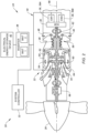
- FIG. 2 diagrammatically illustrates a second present disclosure HEP system 20 embodiment that includes a gas turbine engine 22, a reduction gear box (RGB 28), a propulsor 26, a system controller 32, an electrical power motive system 24, and an accessory gear box (AGB 30).
- a gas turbine engine 22 a reduction gear box (RGB 28), a propulsor 26, a system controller 32, an electrical power motive system 24, and an accessory gear box (AGB 30).
- RGB 28 reduction gear box
- AGB 30 accessory gear box
- the gas turbine engine 22 includes an air inlet 46, a compressor 48, a combustor 50, a high-pressure turbine 52, and a power turbine 54.
- the air inlet 46, the compressor 48, the combustor 50, the high-pressure turbine 52, and the power turbine 54 are arranged along an axial centerline 56 (e.g., a rotational axis) of the gas turbine engine 22.
- the gas turbine engine 22 may be described as having a first rotational assembly 58 and a second rotational assembly 60.
- the first rotational assembly 58 and the second rotational assembly 60 are mounted for rotation about the axial centerline 56.
- the gas turbine engine 22 has a "free turbine" configuration in which power for aircraft propulsion is extracted by the second rotational assembly 60 downstream of (e.g., from the exhaust of) the first rotational assembly 58.
- the present disclosure is not limited to a free turbine configuration.
- forward and aft are used herein to indicate position along the axial centerline 56; referring to the turbine engine shown in FIG. 2 , the power turbine 54 is disposed forward of the high-pressure turbine 52, and the high-pressure turbine 52 is disposed aft of the power turbine 54.
- upstream and downstream are used to indicate position within the gas path of the gas turbine engine 22; e.g., the high-pressure turbine 52 is upstream of the power turbine 54 and the power turbine 54 is downstream of the high-pressure turbine 52 because core gas exits the high-pressure turbine 52 and enters the power turbine 54.
- radial refers to a direction that is perpendicular to the axial centerline and may be used herein to indicate position relative to the axial centerline; e.g., a first component positioned "radially inward" of a second component is disposed closer to the axial centerline than the second component, and conversely the second component is disposed "radially outward" of the first component.
- the first rotational assembly 58 includes a first shaft 62 connecting the compressor 48 to the high-pressure turbine 52.
- the second rotational assembly 60 includes a second shaft 64 connected to the power turbine 54.
- the second shaft 64 may be directly or indirectly connected to the propulsor 26.
- the second shaft 64 may be configured to rotatably drive the propulsor 26 via a reduction gear box 66.
- the reduction gear box 66 may be configured to drive the propulsor 26 at a reduced rotational speed relative to the rotational speed of the second shaft 64.
- ambient air enters the gas turbine engine 22 through the air inlet 46 and is directed into the compressor 48.
- the ambient air is compressed within the compressor 48 and is directed into the combustor 50.
- Fuel is injected into the combustion and is mixed with the compressed air to provide a fuel-air mixture.
- This fuel-air mixture is ignited, and combustion products thereof flow through and sequentially cause the high pressure turbine 52 and the power turbine 54 to rotate.
- the rotation of the high pressure turbine 52 drives rotation of the first rotational assembly 58 and the rotation of the power turbine 54 drives rotation of the second rotational assembly 60.
- the second rotational assembly 60 further drives rotation of the propulsor 26 to provide propulsion (e.g., thrust) for the aircraft.
- motive power to the propulsor 26 may also be provided by an electric motor (e.g., first electric motor 34).
- Combustion exhaust gas flowing past the power turbine 54 is directed out of the gas turbine engine 22 (e.g., through an exhaust).
- the accessory gear box (AGB 30) is in driving communication with the first shaft 62.
- accessory gear boxes are well known and the present disclosure is not limited to any particular accessory gear box configuration.
- a second electric motor 36 (“EM" - or a pair of second electric motors 36A, 36B as shown in FIG. 2 ) may be in communication with the AGB 30.
- a second electric motor 36 may be directly mounted on the first shaft 62 or mounted to be rotationally driven by the compressor 48 or the high pressure turbine 52 thereby obviating the gear reduction of the AGB 30.
- the electrical power motive system 24 in the embodiment of FIG. 2 includes a first electric motor 34, a second electric motor 36 (or a pair of second electric motors 36A, 36B for redundancy), an inverter 38, an electrical distribution bus 40, and an electrical energy storage device 42.
- the inverter 38, electrical distribution bus 40, and electrical energy storage device 42 may be configured as described above.
- the first electric motor 34 is configured to apply a motive force to the second rotational assembly 60.
- the first electric motor 34 may be directly or indirectly coupled to the second shaft 64 to drive the second shaft 64 by applying a motive force to the second shaft 64.
- the first electric motor 34 is diagrammatically shown in FIG. 2 in direct contact with the second shaft 64.
- the present disclosure is not limited to this exemplary configuration of the first electric motor 34.
- the first electric motor 34 may be indirectly connected to the second shaft 64 by a gear box, a clutch, or the like. Accordingly, the first electric motor 34 may be configured to apply a motive force to the second rotational assembly 60 to facilitate driving the propulsor 26 via the second rotational assembly 60.
- the first electric motor 34 in combination with the power turbine 54 may provide the motive force for driving the propulsor 26.
- the first electric motor 34 may also be configured to operate as an electrical generator driven by rotation of the second shaft 64. Accordingly, the first electric motor 34 may also operate as a rotational load on the second shaft 64 to slow the rotational speed of the second shaft 64 and/or to generate electrical energy.
- the first electric motor 34 may be selected to be sufficiently powerful to drive the propulsor 26 during all flight conditions independent of the power turbine 54. In such a case, the first electric motor 34 may provide all of the motive force for driving the propulsor 26.
- the second electric motor 36 may be coupled with the accessory gear box (AGB 30), or mounted elsewhere as described above (e.g., on the first shaft 62, or engaged with the compressor 48 or the high pressure turbine 52).
- the second electric motor 36 may be configured to provide motive force to the first rotational assembly 58, including the first shaft 62 that connects the compressor 48 to the high-pressure turbine 52. Details regarding use of the second electric motor 36 to provide motive force to the first rotational assembly 58, and more specifically to the compressor 48, are provided herein.
- the second electric motor 36 (or motors 36A, 36B) may be configured to operate as an electrical generator driven by rotation of the first shaft 62 via the AGB 30; e.g., operate as a generator when the second electric motor 36 is not being used to provide motive force to the first rotational assembly 58.
- the generator 44 may be configured to supply electrical energy to the electrical power motive system 24.
- the generator 44 is in electrical communication with the electrical distribution bus 40 to supply electrical energy to the system 20 and/or the aircraft.
- the propulsor 26 may be configured as described above.
- the present disclosure provides a system 20 and method for improved control of a gas turbine engine 22 during low engine power settings.
- improved gas turbine engine 22 control would be desirable are as follows.
- the fuel burn rate of a conventional gas turbine engine 22 at very low compressor speeds is normally very inefficient. This is particularly true, for example, in a conventional helicopter engine during descent.
- the present disclosure may be used to improve the fuel efficiency of a gas turbine engine 22 at very low compressor speeds, and/or enable a reduction of the turbine gas temperature of the engine at very low compressor speeds which may improve engine life.
- many conventional gas turbine engines have a rate of power increase at a low engine power setting that is slower / more limited as compared to the rate of power increase possible at high engine power setting.
- the relatively slow / limited rate of power increase can limit the responsiveness of the gas turbine engine 22.
- a person of skill in the art will recognize that conventionally accelerating a gas turbine engine 22 by increasing the fuel flow does not produce instantaneous acceleration; i.e., there is a lag between the moment of acceleration (e.g., the pilot changing the engine power setting by actuating the throttle control) and the engine 22 actually migrating to the changed power setting.
- the present disclosure may be used to improve rate of power increase available at a low engine power setting (or to mitigate lag) and thereby improve the responsiveness of the engine 22.
- An aircraft operational example of where an improved rate of power increase at a low engine power setting would be beneficial is an aircraft aborted landing maneuver.
- An aircraft aborted landing maneuver is also sometimes referred to as a go-around maneuver, which refers to a maneuver where the pilot decides to abort a landing attempt and, in an emergency condition, might require a rapid increase in power to stop descending and avoid an obstacle.
- a helicopter flare maneuver refers to a technique performed prior to touchdown of the helicopter, wherein the pilot controls the aircraft (e.g., by adjusting the rotor blade pitch, or the like) to reduce the aircraft vertical and horizontal speed to facilitate the touchdown.
- the flare maneuver may involve accelerating the gas turbine engine 22 from a low power setting (i.e., descent) to provide increased power quickly to achieve the decrease in aircraft vertical and horizontal speed.
- the present disclosure system may include a first electric motor 34 that provides motive force to the propulsor 26.
- the first electric motor 34 may be controlled to provide limited or no motive force to the propulsor 26 and the propulsor motive force is predominantly or entirely provided by the gas turbine engine 22.
- the first electric motor 34 may be controlled to, but is not required to, function as a generator, producing electrical energy that may be fed back into the electrical distribution bus 40 to charge the electrical energy storage device 42, or to power other electrical components within the electrical power motive system 24; e.g., the second electric motor 36.
- the second electric motor 36 is controlled (e.g., via stored instructions) to selectively provide motive force to the compressor 23, 48 of the gas turbine engine 22 (e.g., during a low engine power setting), thereby applying torque to the compressor 23, 48.
- the second electric motor 36 is coupled with the AGB 30 and the AGB 30 is in communication (directly or indirectly) with the compressor 23 rotational shaft (not shown) of the gas turbine engine 22.
- the second electric motor 36 is controlled to provide motive force to the AGB 30 and the AGB 30 transfers that motive force to the compressor 23 of the gas turbine engine 22.
- FIG. 1 the second electric motor 36 is controlled to selectively provide motive force to the compressor 23, 48 of the gas turbine engine 22 (e.g., during a low engine power setting), thereby applying torque to the compressor 23, 48.
- the second electric motor 36 is coupled with the AGB 30 and the AGB 30 is in communication (directly or indirectly) with the compressor 23 rotational shaft (not shown) of the gas turbine engine 22.
- the second electric motor 36 is controlled to provide motive force
- the second electric motor 36 is in communication with the first rotational assembly 58 either directly or indirectly through the AGB 30.
- the second electric motor 36 is controlled to provide motive force to the AGB 30 and the AGB 30 provides motive force to the first rotational assembly 58 of the gas turbine engine 22, including the compressor 48 thereof.
- the electrical power required to power the second electric motor 36 may be produced by the first electric motor 34 functioning as a generator, or from the electrical energy storage device 42, or from a dedicated generator 44, or any combination thereof.
- the motive force / torque to the compressor 23, 48 augmentation may be applied in a manner that increases the rotational speed of the compressor 23, 48 to a level ("N assist ") above the rotational speed (“N normal ”) it would be operating at for the given fuel flow (N assist > N normal ), and/or the augmentation may be applied in a manner that increases the torque applied to the compressor 23, 48 to a level ("T assist ") above the torque ("T normal ”) that is otherwise applied to the compressor 23, 48 via the connected turbine 27, 52 at the given fuel flow (T assist > T normal ).
- the present disclosure provision of motive force to the compressor 23, 48 of the gas turbine engine 22 via an electric motor 36 (i.e., the augmentation) may be utilized to permit the gas turbine engine 22 to operate at the same power setting or a specific low compressor speed with a decreased fuel flow rate; e.g., the required power from the turbine normally driving the compressor may be decreased because a portion of the motive force driving the compressor is provided by the second electric motor 36.
- the decreased power requirements on the turbine may be satisfied with a decreased fuel flow rate.
- the additional torque from the second electric motor 36 has a similar effect as improved turbine efficiency, with the resulting effect of reducing turbine temperatures, which can improve turbine operating life.
- An additional benefit derived from using torque from the second electric motor 36, is that the compressor speed can be maintained at a higher speed than would otherwise be the case with combustion alone, which means that when called upon to suddenly accelerate to a high speed it is already part of the way to that higher speed target when the fuel flow is increased. This can help to avoid compressor speeds from which the normal engine has limited acceleration capability.
- the present disclosure provision of motive force to the compressor 23, 48 of the gas turbine engine 22 via an electric motor 36 (i.e., the augmentation) may be used to augment compressor performance to mitigate a slow rate of power increase or lag that may be associated with conventional engine acceleration.
- the gas turbine engine 22 response to the acceleration request includes increasing the fuel flow into the combustor.
- the electric motor 36 can be controlled to respond (and thereby provide the augmentation) much more rapidly than the gas turbine engine 22 can respond.
- the slow rate of power increase or lag associated with a conventional gas turbine engine 22 is diminished and engine acceleration response is improved.
- the improvement in engine acceleration response and diminution of lag may provide benefits in aircraft handling and performance.
- a helicopter flare maneuver requires a quick acceleration from an engine low power setting.
- the present disclosure facilitates the quick acceleration; e.g., to provide power quickly, the engine 22 can rapidly increase fuel flow without having to wait for the compressor speed to accelerate from a minimum speed or from a speed lower than the conventional engine's idle speed.
- any one of these structures may describe the operations as a sequential process, many of the operations can be performed in parallel or concurrently.
- the order of the operations may be rearranged.
- a process may correspond to a method, a function, a procedure, a subroutine, a subprogram, etc.
Landscapes
- Engineering & Computer Science (AREA)
- Chemical & Material Sciences (AREA)
- Combustion & Propulsion (AREA)
- Mechanical Engineering (AREA)
- General Engineering & Computer Science (AREA)
- Aviation & Aerospace Engineering (AREA)
- Engine Equipment That Uses Special Cycles (AREA)
- Hybrid Electric Vehicles (AREA)
Applications Claiming Priority (1)
| Application Number | Priority Date | Filing Date | Title |
|---|---|---|---|
| US18/373,237 US12270332B1 (en) | 2023-09-26 | 2023-09-26 | Hybrid-electric aircraft propulsion system control system and method |
Publications (1)
| Publication Number | Publication Date |
|---|---|
| EP4530454A1 true EP4530454A1 (de) | 2025-04-02 |
Family
ID=92925474
Family Applications (1)
| Application Number | Title | Priority Date | Filing Date |
|---|---|---|---|
| EP24203010.4A Pending EP4530454A1 (de) | 2023-09-26 | 2024-09-26 | Steuersystem und -verfahren für ein hybridelektrisches flugzeugantriebssystem |
Country Status (3)
| Country | Link |
|---|---|
| US (1) | US12270332B1 (de) |
| EP (1) | EP4530454A1 (de) |
| CA (1) | CA3255090A1 (de) |
Families Citing this family (1)
| Publication number | Priority date | Publication date | Assignee | Title |
|---|---|---|---|---|
| EP4597786A1 (de) * | 2024-01-31 | 2025-08-06 | Hamilton Sundstrand Corporation | Elektrische leistungsanordnung für antrieb |
Citations (5)
| Publication number | Priority date | Publication date | Assignee | Title |
|---|---|---|---|---|
| US20060225431A1 (en) * | 2005-04-08 | 2006-10-12 | United Technologies Corporation | Electrically coupled supercharger for a gas turbine engine |
| US20100058731A1 (en) * | 2007-04-06 | 2010-03-11 | Turbomeca | Assistance device for transient acceleration and deceleration phases |
| US20100219779A1 (en) * | 2009-03-02 | 2010-09-02 | Rolls-Royce Plc | Variable drive gas turbine engine |
| US20140283519A1 (en) * | 2013-03-25 | 2014-09-25 | Airbus Helicopters | Rotary wing aircraft with a hybrid power plant |
| US20220204171A1 (en) * | 2020-12-28 | 2022-06-30 | Hamilton Sundstrand Corporation | Hybrid propulsion systems |
Family Cites Families (23)
| Publication number | Priority date | Publication date | Assignee | Title |
|---|---|---|---|---|
| US7514810B2 (en) * | 2006-12-15 | 2009-04-07 | General Electric Company | Electric power generation using power turbine aft of LPT |
| US20100251726A1 (en) * | 2007-01-17 | 2010-10-07 | United Technologies Corporation | Turbine engine transient power extraction system and method |
| US8511058B2 (en) * | 2007-11-29 | 2013-08-20 | United Technologies Corporation | Convertible gas turbine propulsion system |
| US20090193785A1 (en) * | 2008-01-31 | 2009-08-06 | General Electric Company | Power generating turbine systems |
| FR2940247B1 (fr) * | 2008-12-19 | 2011-01-21 | Snecma | Systeme d'helices contrarotatives entrainees par un train epicycloidal offrant une repartition de couple equilibree entre les deux helices |
| EP3604764B1 (de) * | 2013-03-07 | 2023-04-19 | Rolls-Royce Corporation | Mehrwellengasturbinentriebwerk |
| FR3024755B1 (fr) * | 2014-08-08 | 2019-06-21 | Safran Aircraft Engines | Hybridation des compresseurs d'un turboreacteur |
| US20170044989A1 (en) * | 2015-08-14 | 2017-02-16 | General Electric Company | Gas turbine engine stall margin management |
| EP3244006B1 (de) * | 2016-03-31 | 2018-11-21 | Rolls-Royce plc | Turbomaschinenwelle |
| US10837304B2 (en) * | 2016-12-13 | 2020-11-17 | General Electric Company | Hybrid-electric drive system |
| US10711700B2 (en) * | 2017-02-01 | 2020-07-14 | Raytheon Technologies Corporation | Gas turbine start system to enable rotor thermal stabilization with backup bleed bypass cooling mode |
| US11731772B2 (en) * | 2017-03-02 | 2023-08-22 | Textron Innovations Inc. | Hybrid propulsion drive train system for tiltrotor aircraft |
| FR3080835B1 (fr) | 2018-05-03 | 2021-04-09 | Safran Helicopter Engines | Systeme propulsif pour un helicoptere |
| US20200056497A1 (en) * | 2018-08-17 | 2020-02-20 | United Technologies Corporation | Hybrid gas turbofan powered sub-idle descent mode |
| EP3931093A4 (de) * | 2019-03-01 | 2022-12-07 | Pratt & Whitney Canada Corp. | Flugzeug mit einem hybrid-elektrischen antriebssystem mit im rumpf beherbergtem stromspeicher |
| US11535392B2 (en) * | 2019-03-18 | 2022-12-27 | Pratt & Whitney Canada Corp. | Architectures for hybrid-electric propulsion |
| FR3102143B1 (fr) | 2019-10-17 | 2023-09-22 | Safran Helicopter Engines | Système propulsif pour un hélicoptère |
| US20210340908A1 (en) * | 2020-05-01 | 2021-11-04 | Raytheon Technologies Corporation | Gas turbine engines having cryogenic fuel systems |
| US11725594B2 (en) * | 2020-08-31 | 2023-08-15 | General Electric Company | Hybrid electric engine speed regulation |
| US20220074349A1 (en) * | 2020-09-08 | 2022-03-10 | Pratt & Whitney Canada Corp. | Split compressor gas turbine engine |
| FR3117450B1 (fr) | 2020-12-11 | 2024-03-01 | Safran Helicopter Engines | Système propulsif hybride pour un hélicoptère |
| GB202200896D0 (en) * | 2022-01-25 | 2022-03-09 | Rolls Royce Plc | Hybrid power system |
| IT202200016215A1 (it) * | 2022-07-29 | 2024-01-29 | Gen Electric | Controllo di sistemi di propulsione e trasmissione completamente elettrici o ibridi-elettrici |
-
2023
- 2023-09-26 US US18/373,237 patent/US12270332B1/en active Active
-
2024
- 2024-09-25 CA CA3255090A patent/CA3255090A1/en active Pending
- 2024-09-26 EP EP24203010.4A patent/EP4530454A1/de active Pending
Patent Citations (5)
| Publication number | Priority date | Publication date | Assignee | Title |
|---|---|---|---|---|
| US20060225431A1 (en) * | 2005-04-08 | 2006-10-12 | United Technologies Corporation | Electrically coupled supercharger for a gas turbine engine |
| US20100058731A1 (en) * | 2007-04-06 | 2010-03-11 | Turbomeca | Assistance device for transient acceleration and deceleration phases |
| US20100219779A1 (en) * | 2009-03-02 | 2010-09-02 | Rolls-Royce Plc | Variable drive gas turbine engine |
| US20140283519A1 (en) * | 2013-03-25 | 2014-09-25 | Airbus Helicopters | Rotary wing aircraft with a hybrid power plant |
| US20220204171A1 (en) * | 2020-12-28 | 2022-06-30 | Hamilton Sundstrand Corporation | Hybrid propulsion systems |
Also Published As
| Publication number | Publication date |
|---|---|
| CA3255090A1 (en) | 2025-04-01 |
| US20250101909A1 (en) | 2025-03-27 |
| US12270332B1 (en) | 2025-04-08 |
Similar Documents
| Publication | Publication Date | Title |
|---|---|---|
| EP2990626B1 (de) | Betrieb von flugzeugmotoren während transient-bedingungen | |
| CN114056582A (zh) | 飞行器混合推进系统 | |
| US12296941B2 (en) | System and method for controlling a propulsor for a hybrid-electric aircraft propulsion system | |
| KR20130140023A (ko) | 항공기 가스 터빈으로 인가되는 전기의 발생을 제어하기 위한 방법 및 상기 방법을 구현하는 장치 | |
| EP4524384A1 (de) | Motoranordnung für ein flugzeugantriebssystem | |
| EP4530454A1 (de) | Steuersystem und -verfahren für ein hybridelektrisches flugzeugantriebssystem | |
| EP4467803A1 (de) | Systeme und verfahren zur steuerung eines elektrischen verteilungssystems für ein hybridelektrisches flugzeugantriebssystem | |
| US20220194615A1 (en) | Aircraft propulsion system | |
| US12415498B2 (en) | Hybrid engine system and method of controlling the same | |
| EP4464873A1 (de) | Bremssteuerungsanordnung für ein flugzeuggasturbinentriebwerk und verfahren zur verwendung davon | |
| EP4491444A1 (de) | Systeme und verfahren zur steuerung eines batteriepackaustausches für ein flugzeug | |
| US12467513B2 (en) | Method and apparatus for actively damping vibrations in a hybrid-electric aircraft propulsion system | |
| US20260001653A1 (en) | Systems and methods for controlling an electric motor of an aircraft propulsion system | |
| US20230278713A1 (en) | Power unit control system, power unit control method, and power unit control program | |
| US12545419B1 (en) | Emergency energy protection assembly for hybrid-electric aircraft propulsion systems | |
| US12545418B2 (en) | Control assembly for aircraft propulsion systems | |
| EP4474630A1 (de) | System und verfahren zur steuerung von motoren einer mehrmotorigen flugzeugmotoranordnung | |
| JP7511536B2 (ja) | 航空機の推進システム | |
| EP4477866A2 (de) | System und verfahren zur steuerung von motoren einer mehrmotorigen flugzeugmotoranordnung | |
| EP4678535A1 (de) | Hybrides elektrisches antriebssystem mit regeneration und verfahren zum betrieb davon | |
| US20250010756A1 (en) | Systems and methods for controlling a battery pack loadout for an aircraft |
Legal Events
| Date | Code | Title | Description |
|---|---|---|---|
| PUAI | Public reference made under article 153(3) epc to a published international application that has entered the european phase |
Free format text: ORIGINAL CODE: 0009012 |
|
| STAA | Information on the status of an ep patent application or granted ep patent |
Free format text: STATUS: THE APPLICATION HAS BEEN PUBLISHED |
|
| AK | Designated contracting states |
Kind code of ref document: A1 Designated state(s): AL AT BE BG CH CY CZ DE DK EE ES FI FR GB GR HR HU IE IS IT LI LT LU LV MC ME MK MT NL NO PL PT RO RS SE SI SK SM TR |
|
| STAA | Information on the status of an ep patent application or granted ep patent |
Free format text: STATUS: REQUEST FOR EXAMINATION WAS MADE |
|
| 17P | Request for examination filed |
Effective date: 20251002 |