EP4464873A1 - Bremssteuerungsanordnung für ein flugzeuggasturbinentriebwerk und verfahren zur verwendung davon - Google Patents
Bremssteuerungsanordnung für ein flugzeuggasturbinentriebwerk und verfahren zur verwendung davon Download PDFInfo
- Publication number
- EP4464873A1 EP4464873A1 EP24176782.1A EP24176782A EP4464873A1 EP 4464873 A1 EP4464873 A1 EP 4464873A1 EP 24176782 A EP24176782 A EP 24176782A EP 4464873 A1 EP4464873 A1 EP 4464873A1
- Authority
- EP
- European Patent Office
- Prior art keywords
- assembly
- electrical terminal
- switch
- contact position
- rotational assembly
- Prior art date
- Legal status (The legal status is an assumption and is not a legal conclusion. Google has not performed a legal analysis and makes no representation as to the accuracy of the status listed.)
- Pending
Links
Images


Classifications
-
- H—ELECTRICITY
- H02—GENERATION; CONVERSION OR DISTRIBUTION OF ELECTRIC POWER
- H02P—CONTROL OR REGULATION OF ELECTRIC MOTORS, ELECTRIC GENERATORS OR DYNAMO-ELECTRIC CONVERTERS; CONTROLLING TRANSFORMERS, REACTORS OR CHOKE COILS
- H02P9/00—Arrangements for controlling electric generators for the purpose of obtaining a desired output
- H02P9/08—Control of generator circuit during starting or stopping of driving means, e.g. for initiating excitation
-
- F—MECHANICAL ENGINEERING; LIGHTING; HEATING; WEAPONS; BLASTING
- F01—MACHINES OR ENGINES IN GENERAL; ENGINE PLANTS IN GENERAL; STEAM ENGINES
- F01D—NON-POSITIVE DISPLACEMENT MACHINES OR ENGINES, e.g. STEAM TURBINES
- F01D19/00—Starting of machines or engines; Regulating, controlling, or safety means in connection therewith
-
- F—MECHANICAL ENGINEERING; LIGHTING; HEATING; WEAPONS; BLASTING
- F01—MACHINES OR ENGINES IN GENERAL; ENGINE PLANTS IN GENERAL; STEAM ENGINES
- F01D—NON-POSITIVE DISPLACEMENT MACHINES OR ENGINES, e.g. STEAM TURBINES
- F01D21/00—Shutting-down of machines or engines, e.g. in emergency; Regulating, controlling, or safety means not otherwise provided for
- F01D21/006—Arrangements of brakes
-
- F—MECHANICAL ENGINEERING; LIGHTING; HEATING; WEAPONS; BLASTING
- F01—MACHINES OR ENGINES IN GENERAL; ENGINE PLANTS IN GENERAL; STEAM ENGINES
- F01D—NON-POSITIVE DISPLACEMENT MACHINES OR ENGINES, e.g. STEAM TURBINES
- F01D21/00—Shutting-down of machines or engines, e.g. in emergency; Regulating, controlling, or safety means not otherwise provided for
- F01D21/02—Shutting-down responsive to overspeed
-
- F—MECHANICAL ENGINEERING; LIGHTING; HEATING; WEAPONS; BLASTING
- F02—COMBUSTION ENGINES; HOT-GAS OR COMBUSTION-PRODUCT ENGINE PLANTS
- F02C—GAS-TURBINE PLANTS; AIR INTAKES FOR JET-PROPULSION PLANTS; CONTROLLING FUEL SUPPLY IN AIR-BREATHING JET-PROPULSION PLANTS
- F02C7/00—Features, components parts, details or accessories, not provided for in, or of interest apart form groups F02C1/00 - F02C6/00; Air intakes for jet-propulsion plants
- F02C7/26—Starting; Ignition
- F02C7/268—Starting drives for the rotor, acting directly on the rotor of the gas turbine to be started
-
- F—MECHANICAL ENGINEERING; LIGHTING; HEATING; WEAPONS; BLASTING
- F02—COMBUSTION ENGINES; HOT-GAS OR COMBUSTION-PRODUCT ENGINE PLANTS
- F02C—GAS-TURBINE PLANTS; AIR INTAKES FOR JET-PROPULSION PLANTS; CONTROLLING FUEL SUPPLY IN AIR-BREATHING JET-PROPULSION PLANTS
- F02C7/00—Features, components parts, details or accessories, not provided for in, or of interest apart form groups F02C1/00 - F02C6/00; Air intakes for jet-propulsion plants
- F02C7/32—Arrangement, mounting, or driving, of auxiliaries
-
- H—ELECTRICITY
- H02—GENERATION; CONVERSION OR DISTRIBUTION OF ELECTRIC POWER
- H02K—DYNAMO-ELECTRIC MACHINES
- H02K7/00—Arrangements for handling mechanical energy structurally associated with dynamo-electric machines, e.g. structural association with mechanical driving motors or auxiliary dynamo-electric machines
- H02K7/20—Structural association with auxiliary dynamo-electric machines, e.g. with electric starter motors or exciters
-
- F—MECHANICAL ENGINEERING; LIGHTING; HEATING; WEAPONS; BLASTING
- F05—INDEXING SCHEMES RELATING TO ENGINES OR PUMPS IN VARIOUS SUBCLASSES OF CLASSES F01-F04
- F05D—INDEXING SCHEME FOR ASPECTS RELATING TO NON-POSITIVE-DISPLACEMENT MACHINES OR ENGINES, GAS-TURBINES OR JET-PROPULSION PLANTS
- F05D2220/00—Application
- F05D2220/50—Application for auxiliary power units (APU's)
-
- F—MECHANICAL ENGINEERING; LIGHTING; HEATING; WEAPONS; BLASTING
- F05—INDEXING SCHEMES RELATING TO ENGINES OR PUMPS IN VARIOUS SUBCLASSES OF CLASSES F01-F04
- F05D—INDEXING SCHEME FOR ASPECTS RELATING TO NON-POSITIVE-DISPLACEMENT MACHINES OR ENGINES, GAS-TURBINES OR JET-PROPULSION PLANTS
- F05D2220/00—Application
- F05D2220/70—Application in combination with
- F05D2220/76—Application in combination with an electrical generator
-
- F—MECHANICAL ENGINEERING; LIGHTING; HEATING; WEAPONS; BLASTING
- F05—INDEXING SCHEMES RELATING TO ENGINES OR PUMPS IN VARIOUS SUBCLASSES OF CLASSES F01-F04
- F05D—INDEXING SCHEME FOR ASPECTS RELATING TO NON-POSITIVE-DISPLACEMENT MACHINES OR ENGINES, GAS-TURBINES OR JET-PROPULSION PLANTS
- F05D2260/00—Function
- F05D2260/85—Starting
-
- F—MECHANICAL ENGINEERING; LIGHTING; HEATING; WEAPONS; BLASTING
- F05—INDEXING SCHEMES RELATING TO ENGINES OR PUMPS IN VARIOUS SUBCLASSES OF CLASSES F01-F04
- F05D—INDEXING SCHEME FOR ASPECTS RELATING TO NON-POSITIVE-DISPLACEMENT MACHINES OR ENGINES, GAS-TURBINES OR JET-PROPULSION PLANTS
- F05D2260/00—Function
- F05D2260/90—Braking
- F05D2260/903—Braking using electrical or magnetic forces
Definitions
- This disclosure relates generally to aircraft gas turbine engines and, more particularly, to a braking control assembly for an aircraft gas turbine engine.
- Gas turbine engines for aircraft propulsion systems and auxiliary power units may be susceptible to windmilling during various operating conditions of the gas turbine engines.
- Various systems and methods are known in the art for preventing or mitigating gas turbine engine windmilling. While these known systems and methods have various advantages, there is still room in the art for improvement.
- an assembly for a gas turbine engine of an aircraft includes a rotational assembly, a starter generator, and a control relay.
- the starter generator is coupled with the rotational assembly.
- the starter generator is configured to selectively drive rotation of the rotational assembly.
- the starter generator includes a motor winding including a first electrical terminal and a second electrical terminal.
- the control relay includes a switch electrically connected to the first electrical terminal. The switch is positionable in a first contact position and a second contact position, in the first contact position, the first electrical terminal is electrically isolated from the second electrical terminal through the switch. In the second contact position, the first electrical terminal is electrically connected to the second electrical terminal through the switch such that a closed electrical circuit is formed through the motor winding, the first electrical terminal, the second electrical terminal, and the switch.
- the assembly may further include a battery electrically connected to the starter generator and the switch such that, in the first contact position, the battery is configured to supply electrical power to the starter generator.
- the starter generator may be configured to drive rotation of the rotational assembly with the switch in the first contact position.
- the starter generator may be configured to resist rotation of the rotational assembly with the switch in the second contact position.
- the starter generator may be coupled with the rotational assembly by a gearbox.
- the rotational assembly may include a shaft, a bladed compressor rotor, and a bladed turbine rotor.
- the shaft may interconnect the bladed compressor rotor and the bladed turbine rotor.
- the assembly may further include a main generator coupled with the rotational assembly.
- the rotational assembly may be configured to drive rotation of the main generator.
- control relay may include a variable resistor. With the switch in the second contact position, the variable resistor may be configured to selectively vary an electrical resistance between the first electrical terminal and the second electrical terminal.
- the assembly may further include a controller connected in communication with the control relay.
- the controller may include a processor in communication with a non-transitory memory storing instructions, which instructions when executed by the processor, may cause the processor to control the control relay to position the switch in the first contact position or the second contact position.
- the instructions when executed by the processor, may further cause the processor to control the control relay to position the switch in the second contact position during a shutdown process for the gas turbine engine.
- the instructions when executed by the processor, may further cause the processor to control the control relay to position the switch in the second contact position during the shutdown process for the gas turbine engine when a rotation speed of the rotational assembly decreases to or below a rotation speed threshold value.
- the instructions when executed by the processor, may further cause the processor to control the control relay to position the switch in the second contact position during a flight condition of the aircraft.
- the instructions when executed by the processor, may further cause the processor to control the control relay to position the switch in the second contact position during an overspeed condition of the rotational assembly.
- control relay may include a variable resistor connected in communication with the controller.
- the variable resistor may be configured to selectively vary an electrical resistance between the first electrical terminal and the second electrical terminal with the switch in the second contact position.
- the instructions when executed by the processor, may further cause the processor to control the variable resistor to control the electrical resistance between the first electrical terminal and the second electrical terminal.
- a method for controlling braking for a gas turbine engine of an aircraft includes identifying a windmilling condition of a rotational assembly of the gas turbine engine and controlling braking for the rotational assembly, in response to identifying the windmilling condition, with a starter generator coupled to the rotational assembly by electrically connecting a first electrical terminal and a second electrical terminal of a motor winding of the starter generator together with a control relay to apply a braking force to the rotational assembly with the starter generator.
- the method may further include controlling an electrical resistance between the first electrical terminal and the second electrical terminal to control a magnitude of the braking force applied to the rotational assembly with the starter generator.
- identifying the windmilling condition may include identifying a rotation speed of the rotational assembly is greater than or equal to a rotation speed threshold value while the gas turbine engine is inoperative.
- an assembly for a gas turbine engine of an aircraft includes a main generator, a rotational assembly, a starter generator, and a control relay.
- the rotational assembly includes a shaft, a bladed compressor rotor, and a bladed turbine rotor.
- the shaft interconnects the bladed compressor rotor and the bladed turbine rotor.
- the rotational assembly is coupled with the main generator and configured to drive rotation of the main generator.
- the starter generator is coupled with the rotational assembly.
- the starter generator is configured to selectively drive rotation of the rotational assembly.
- the starter generator includes a motor winding including a first electrical terminal and a second electrical terminal.
- the control relay includes a switch positionable in a contact position to directly electrically connect the first electrical terminal to the second electrical terminal.
- the assembly may further include a controller connected in communication with the control relay.
- the controller may include a processor in communication with a non-transitory memory storing instructions, which instructions when executed by the processor, may cause the processor to: identify a windmilling condition of the rotational assembly and control the control relay to position the switch in the contact position in response to the identified windmilling condition.
- control relay may include a variable resistor. With the switch in the contact position, the variable resistor may be configured to selectively vary an electrical resistance between the first electrical terminal and the second electrical terminal.
- FIG. 1 illustrates an aircraft 100 including at least one propulsion system 102.
- the aircraft 100 of FIG. 1 is configured as a fixed-wing aircraft (e.g., an airplane). However, the present disclosure is equally applicable to other aircraft 100 configurations such as, but not limited to, a rotary-wing aircraft (e.g., a helicopter), a tilt-rotor aircraft, a tilt-wing aircraft, or any other aerial vehicle.
- the aircraft 100 may be a manned aerial vehicle or an unmanned aerial vehicle (UAV, e.g., a drone).
- the propulsion system 102 of FIG. 1 is configured as a turboprop gas turbine engine.
- the aircraft 100 is not limited to any particular propulsion system configuration and the present disclosure is also applicable to aircraft propulsion systems including other gas turbine engine configurations (e.g., a turbofan gas turbine engine, a turboshaft gas turbine engine, a turbojet gas turbine engine, etc.) as well as rotary engines, internal combustion piston engines, a hybrid-electric internal combustion engines, battery-electric propulsion systems, or the like.
- gas turbine engine configurations e.g., a turbofan gas turbine engine, a turboshaft gas turbine engine, a turbojet gas turbine engine, etc.
- rotary engines e.g., a turbofan gas turbine engine, a turboshaft gas turbine engine, a turbojet gas turbine engine, etc.
- internal combustion piston engines e.g., a hybrid-electric internal combustion engines, battery-electric propulsion systems, or the like.
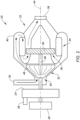
- FIG. 2 illustrates an auxiliary power unit (APU) 20 for the aircraft 100 (see FIG. 1 ).
- the APU 20 is configured to supply electricity, compressed air (e.g., compressor bleed air), or hydraulics, or other functions for the aircraft 100 and/or its propulsion systems 102 (see FIG. 1 ).
- the APU 20 may supply electricity and/or compressed air to the aircraft 100 while the propulsion system 102 is inoperative, for example, when the aircraft 100 is on the ground.
- the APU 20 may also operate to supply electricity or compressed air for starting the propulsion system 102 (e.g., initiating an ignition process for the propulsion system 102).
- the APU 20 of FIG. 2 includes a gas turbine engine 22, a gearbox 24, a main generator 26, and a starter generator 28.
- the gas turbine engine 22 of FIG. 2 includes an air inlet 30, a compressor 32, a combustor 34 (e.g., an annular combustor), a turbine 36, an exhaust 38, and an engine static structure 40.
- the engine static structure 40 may include, for example, one or more engine cases for the gas turbine engine 22.
- the engine static structure 40 may additionally include cowlings, bearing assemblies, or other structural components of the gas turbine engine 22.
- the one or more engine cases form, house, and/or structurally support the gas turbine engine 22 components 30, 32, 34, 36, and 38. It should be understood that the APU 20 and its gas turbine engine 22 of FIG. 2 are exemplary and the present disclosure is not limited to the particular APU 20 and/or gas turbine engine 22 configuration of FIG. 2 .
- the compressor 32 and the turbine 36 are formed, in part, by a rotational assembly 42 (e.g., a spool) of the gas turbine engine 22.
- the first rotational assembly 42 is mounted for rotation about an axial centerline 44 of the gas turbine engine 22 relative to the engine static structure 40.
- the rotational assembly 42 includes a bladed compressor rotor 46 (e.g., a centrifugal impeller) for the compressor 32, a shaft 48, and a bladed turbine rotor 50 for the turbine 36.
- the shaft 48 interconnects the bladed compressor rotor 46 and the bladed turbine rotor 50.
- the shaft 48 is additionally connected to the gearbox 24.
- ambient air enters the gas turbine engine 22 through the air inlet 30.
- the air is compressed by the bladed compressor rotor 46 and directed into a combustion chamber of the combustor 34.
- Fuel is injected into the combustion chamber and mixed with the compressed air to form a fuel-air mixture.
- This fuel-air mixture is ignited, and combustion products thereof flow through and cause the bladed turbine rotor 50 to rotate.
- the rotation of the bladed turbine rotor 50 drives rotation of the rotational assembly 42.
- the combustion exhaust gas flowing through the bladed turbine rotor 50 is directed out of the gas turbine engine 22 through the exhaust 36.
- the gearbox 24 is connected to the shaft 48, as previously discussed.
- the gearbox 24 includes a gear assembly (e.g., an epicyclic gear assembly) connected to the shaft 48, which gear assembly is configured to be driven by rotation of the shaft 48.
- the gearbox 24 may be configured as a speed-changing gearbox.
- the gearbox 24 may be configured to drive rotation of the main generator 26 (e.g., an input shaft of the main generator 26) at a different (e.g., a reduced) rotation speed relative to the shaft 48.
- the main generator 26 is connected to the gearbox 24.
- the main generator 26 is configured to be driven by the gearbox 24 to generate electric power for the aircraft 100 and/or its propulsion system 102 (see FIG. 1 ), for example, when the electrical power from the propulsion system 102 or from ground power sources is not available.
- the main generator 26 may be configured to supply electric power for electrical loads of the aircraft 100 such as, but not limited to, aircraft control systems, environmental control systems (ECS), lighting, and the like.
- the starter generator 28 (e.g., a brushless starter generator (BSG)) is coupled to the rotational assembly 42.
- the starter generator 28 is connected to the gearbox 24 with the gearbox 24 operably coupling the starter generator 28 and the rotational assembly 42.
- the starter generator 28 may alternatively be directly connected to the rotational assembly 42 (e.g., the shaft 48) or indirectly connected to the rotational assembly 42 by a discrete gearbox (e.g., separate from the gearbox 24), a clutch, or the like.
- the starter generator 28 is configured to selectively drive rotation of the rotational assembly 42 (e.g., via the gearbox 24).
- the starter generator is configured to facilitate an engine start sequence for the gas turbine engine 22 by applying a rotational force to the gearbox 24 to rotate the shaft 48.
- the starter generator 28 may be configured as a direct current (DC) electric motor.
- the starter generator 28 may be powered by a DC electrical power source to apply the rotational force to the gearbox 24 to rotate the shaft 48.
- the starter generator 28 may additionally be configured to generate electrical power.
- the shaft 48 and the gearbox 24 may drive rotation of the starter generator 28 to generate electrical power.
- the starter generator 28 may generate electrical power in combination with the main generator 26.
- the main generator 26 may generate electrical power for a high-voltage (e.g., greater than 60 volts) electrical distribution system of the aircraft 100 and/or its propulsion system 102 while the starter generator may generate electrical power for a low-voltage (e.g., less than 60v) electrical distribution system of the aircraft 100 and/or its propulsion system 102 (see FIG. 1 ).
- a high-voltage e.g., greater than 60 volts
- the starter generator may generate electrical power for a low-voltage (e.g., less than 60v) electrical distribution system of the aircraft 100 and/or its propulsion system 102 (see FIG. 1 ).
- the APU 20 may be inoperative.
- the APU 20 may be inoperative during a flight condition of the aircraft 100, for example, where the propulsion system 102 may be supplying electrical power for the aircraft 100.
- ambient air flow through components of the APU 20 may cause rotational components of the APU 20, such as the rotational assembly 42, to windmill (e.g., rotate due to ambient air flow).
- the windmilling effect may cause undesirable wear to APU 20 components.
- the windmilling effect may additionally or alternatively cause lubricating fluid to circulate through the APU 20, thereby increasing a risk of fire in the APU 20.
- the APU 20 may be operating.
- the gas turbine engine 22 may be driving rotation of the main generator 26 to generate electrical power for the aircraft 100 and/or its propulsion system 102.
- the gas turbine engine 22 may experience an overspeed condition. For example, a sudden decrease in electrical loading of the main generator 26 may cause a rotation speed of the rotational assembly 42 to rapidly increase, thereby presenting an increased risk of damage to gas turbine engine 22 components.
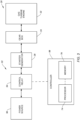
- the APU 20 includes a braking control assembly 52 configured to effect braking for the gas turbine engine 22 (e.g., the rotational assembly 42) using the starter generator 28.
- the braking control assembly 52 includes a control relay 54 configured, in part, to control a supply of electrical power from a power source 56 (e.g., a DC power source) to the starter generator 28 to control operation of the starter generator 28 for facilitating an engine start sequence for the gas turbine engine 22 via the gearbox 24, as previously discussed.
- the power source 56 may be one or more batteries, one or more capacitors, or any other suitable device for storing electrical energy.
- the braking control assembly 52 may additionally include a controller 58.
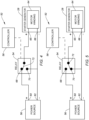
- FIGS. 4 and 5 schematically illustrate the control relay 54 electrically connected with the starter generator 28 and the power source 56.
- FIG. 4 illustrates the control relay 54 is a starter mode condition.
- FIG. 5 illustrates the control relay 54 in a braking mode condition.
- the power source 56 of FIGS. 4 and 5 includes a first electrical terminal 60 (e.g., a positive terminal) and a second electrical terminal 62 (e.g., a negative terminal).
- the starter generator 28 includes a motor winding 64 (e.g., an electrically conductive coil) having a first electrical terminal 65 (e.g., a positive terminal) and a second electrical terminal 66 (e.g., a negative terminal), such that electrical current flows from one of the first electrical terminal 65 or the second electrical terminal 66, through the motor winding 64, and to the other of the first electrical terminal 65 or the second electrical terminal 66.
- the motor winding 64 may form a portion of a stator for the starter generator 28.
- the control relay 54 includes a first contact 68 (e.g., a positive contact), a second contact 70 (e.g., a negative contact), and a switch 72.
- the first electrical terminal 60 is electrically connected to the first contact 68.
- the first electrical terminal 65 is electrically connected to the switch 72 (e.g., directly electrically connected to the switch 72, for example, by an insulated wire).
- the second electrical terminal 62 is electrically connected to the second contact 70.
- the second electrical terminal 66 is also electrically connected to the second contact 70 (e.g., directly electrically connected to the second contact 70, for example, by an insulated wire).
- the switch 72 is selectively positionable in electrical contact with the first contact 68 (e.g., a first contact position of the switch 72) or the second contact 70 (e.g., a second contact position of the switch 72).
- the switch 72 may be manually operated (e.g., physically or remotely) by a pilot or other operator to position the switch 72 in electrical contact with the first contact 68 or the second contact 70.
- FIGS. 4 and 5 described above are exemplary and various different electrical connection configurations between the starter generator 28, the control relay 54, and the power source 56 could be made to accomplish functions of the braking control assembly 52 described herein.
- the controller 58 is connected in signal communication with the control relay 54.
- the controller 58 includes a processor 74 connected in signal communication with memory 76.
- the processor 74 may include any type of computing device, computational circuit, processor(s), CPU, computer, or the like capable of executing a series of instructions that are stored in the memory 76. Instructions can be directly executable or can be used to develop executable instructions. For example, instructions can be realized as executable or non-executable machine code or as instructions in a high-level language that can be compiled to produce executable or non-executable machine code. Further, instructions also can be realized as or can include data.
- Computer-executable instructions also can be organized in any format, including routines, subroutines, programs, data structures, objects, modules, applications, applets, functions, etc.
- the instructions may include an operating system, and/or executable software modules such as program files, system data, buffers, drivers, utilities, and the like.
- the executable instructions may apply to any functionality described herein to enable the aircraft 100, the APU 20, and/or the control relay 54 to accomplish the same algorithmically and/or by coordination of the APU 20 components.
- the memory 76 may include a single memory device or a plurality of memory devices; e.g., a computer-readable storage device that can be read, written, or otherwise accessed by a general purpose or special purpose computing device, including any processing electronics and/or processing circuitry capable of executing instructions.
- the present disclosure is not limited to any particular type of memory device, which may be non-transitory, and may include read-only memory, random access memory, volatile memory, non-volatile memory, static memory, dynamic memory, flash memory, cache memory, volatile or non-volatile semiconductor memory, optical disk storage, magnetic disk storage, magnetic tape, other magnetic storage devices, or any other medium capable of storing one or more instructions, and/or any device that stores digital information.
- the memory device(s) may be directly or indirectly coupled to the controller 58.
- the controller 58 may include, or may be in communication with, an input device that enables a user to enter data and/or instructions, and may include, or be in communication with, an output device configured, for example to display information (e.g., a visual display or a printer), or to transfer data, etc.
- Communications between the controller 58 and other electrical and/or electronic components may be via a hardwire connection or via a wireless connection.
- portions of the controller 58 may assume various forms (e.g., digital signal processor, analog device, etc.) capable of performing the functions described herein.
- the controller 58 may form or otherwise be part of an electronic engine controller (EEC) for the APU 20.
- EEC electronic engine controller
- the EEC may control operating parameters of the gas turbine engine 22 including, but not limited to, fuel flow, stator vane position (e.g., variable compressor inlet guide vane (IGV) position), compressor air bleed valve position, shaft (e.g., shaft 48) torque and/or rotation speed, etc. so as to control an engine power or performance of the APU 20.
- the EEC may modulate fuel flow to the combustor 34 to obtain a desired output power of the gas turbine engine 22.
- the EEC may modulate the fuel flow using a closed-loop process in which an output power or other operating parameter of the gas turbine engine 22 is measured and fuel flow is increased or decreased as a function of the measured output power or operational parameter.
- the controller 58 may include or otherwise be connected in signal communication with one or more sensors to measure the output power or operational parameters such as, but not limited, shaft rotation speed sensors, shaft torque sensors, fuel flow rate sensors, pressure sensors, temperature sensors, and the like.
- the EEC may be part of a full authority digital engine control (FADEC) system for the aircraft 100 (see FIG. 1 ).
- FADEC full authority digital engine control
- the switch 72 may be positioned in contact with the first contact 68 or the second contact 70 to place the control relay 54 in the starter mode condition (see FIG. 4 ) or the braking mode condition (see FIG. 5 ), respectively.
- the control relay 54 may be placed in the starter mode condition before or during operation of the gas turbine engine 22 (see FIGS. 2 and 3 ). With the control relay 54 in the starter mode condition, the switch 72 is positioned in contact with the first contact 68, thereby forming an electrical flow path (e.g., a circuit) between the power source 56 and the starter generator 28.
- the control relay 54 may be placed in the starter mode condition before operation of the gas turbine engine 22 to supply electrical power from the power source 56 to the starter generator 28 to facilitate an engine start sequence for the gas turbine engine 22 by applying a rotational force to the gearbox 24 with the starter generator 28 to rotate the shaft 48.
- the control relay 54 may be placed in (or may remain in after the engine start sequence) the starter mode condition during operation of the gas turbine engine 22 to facilitate electrical generation using the starter generator 28, as described above.
- the electrical power generated by the starter generator 28 may be used to power one or more electrical loads and/or may be stored by the power source 56.
- the control relay 54 may be placed in the braking mode condition during an inoperative condition of the gas turbine engine 22.
- the control relay 54 may be placed in the braking mode condition during a flight condition of the aircraft 100 (see FIG 1 ), facilitate reduced or prevented windmilling of the gas turbine engine 22 components.
- the switch 72 With the control relay 54 in the braking mode condition, the switch 72 is positioned in contact with the second contact 70, thereby directly electrically connecting the first electrical terminal 65 and the second electrical terminal 66 of the starter generator 28 together through the switch 72 such that a closed electrical circuit is formed through the motor winding 64, the first electrical terminal 65, the second electrical terminal 66, and the switch 72.
- windmilling of the rotational assembly 42 may rotationally drive the starter generator 28 (e.g., via the gearbox 24) inducing an electrical current flow in the motor winding 64 and through the electrically-connect terminals 65, 66, forming a magnetic field in opposition to a magnetic field (e.g., a permanent magnet magnetic field) of a rotor of the starter generator 28, and thereby applying a braking force to the rotational assembly 42 by opposing rotation (e.g., windmilling) of the rotational assembly 42.
- the control relay 54 may be placed in the braking mode condition in an operational condition of the gas turbine engine 22 in response to or in expectation of an overspeed condition for the gas turbine engine 22 (e.g., the rotational assembly 42).
- the switch 72 With the switch 72 is positioned in contact with the second contact 70, the electrical flow path between the power source 56 and the starter generator 28 is interrupted. In other words, with the switch 72 is positioned in contact with the second contact 70, the power source 56 cannot supply electrical power to the starter generator 28 and the starter generator cannot supply electrical power to the power source 56.
- the controller 58 may be configured to control a condition (e.g., the starter mode condition or the braking mode condition) for the control relay 54 based on one or more conditions or operations of the APU 20.
- the memory 76 may include instructions which, when executed by the processor 74, cause the processor 74 to control a contact position of the switch 72.
- the controller 58 may be configured to place the control relay 54 in the braking mode condition during a shutdown process for the APU 20 to prevent subsequent windmilling of the rotational assembly 42 as the rotational assembly 42 slows or stops. Accordingly, the control relay 54 may be placed in the braking mode condition as the rotational assembly 42 approaches a stopped condition. The controller 58 may place the control relay 54 in the braking mode condition once a rotation speed of the rotational assembly 42 reaches a rotation speed threshold value.
- the rotation speed threshold value may be selected to correspond to a sufficiently low rotation speed of the rotational assembly 42 such that the starter generator 28 does not experience excessive heating during the braking process. For example, the rotation speed threshold value may be a rotation speed which is less than or equal to ten percent of a rated rotation speed for the rotational assembly 42.
- the controller 58 may be configured to identify a windmilling condition of the rotational assembly 42 and place the control relay 54 in the braking mode condition in response to the identified windmilling condition.
- the controller 58 may be configured to identify rotation (e.g., a rotation speed) of the rotational assembly 42 while the APU 20 is inoperative. Identification of the windmilling condition may be identified by the controller 58 if a rotation speed of the rotational assembly 42 is greater than or equal to a first rotation speed threshold value.
- the controller 58 may be configured to place the control relay 54 in the braking mode condition, for example, until the rotation speed of the rotational assembly 42 decreases to or below a second rotation speed threshold value (e.g., less than the first rotation speed threshold value), at which point the controller 58 may place the control relay 54 in the starter mode condition. Alternatively, the controller 58 may cause the control relay 54 to remain in the braking mode condition until startup of the APU 20 is desired.
- the controller 58 may additionally or alternatively be configured to place the control relay 54 in the braking mode condition after identifying one or more operational conditions of the aircraft 100, the propulsion system 102, and/or the APU 20, in which operating conditions windmilling of the rotational assembly 42 may be likely (e.g., during flight, during taxiing, etc.).
- the controller 58 may be configured to identify a casualty condition of the APU 20 (e.g., a fire) and place the control relay 54 in the braking mode condition in response to the identified casualty condition. Braking of the rotational assembly 42 by placing the control relay 54 in the braking mode condition may mitigate fire damage to the APU 20 and/or the aircraft 100 by preventing windmilling of the rotational assembly 42, which windmilling may cause flammable or otherwise combustible lubricating fluid to circulate within the APU 20.
- a casualty condition of the APU 20 e.g., a fire
- Braking of the rotational assembly 42 by placing the control relay 54 in the braking mode condition may mitigate fire damage to the APU 20 and/or the aircraft 100 by preventing windmilling of the rotational assembly 42, which windmilling may cause flammable or otherwise combustible lubricating fluid to circulate within the APU 20.
- the controller 58 may be configured to identify an overspeed condition of the rotational assembly 42 and place the control relay 54 in the braking mode condition in response to the identified overspeed condition. For example, the controller 58 may be configured to identify a rotation speed of the rotational assembly 42 which exceeds a first rotation speed threshold value. The controller 58 may be configured to place the control relay 54 in the braking mode condition, for example, until the rotation speed of the rotational assembly 42 decreases to or below a second rotation speed threshold value (e.g., less than the first rotation speed threshold value), at which point the controller 58 may place the control relay 54 in the starter mode condition.
- the first rotation speed threshold value and the second rotation speed threshold value may be selected or determined by the controller 58 based, for example, on a target rotation speed value for the rotational assembly 42.
- the control relay 54 may include a variable resistor 78.
- the variable resistor 78 is configured to selectively vary an electrical resistance for electrical current flow through the variable resistor 78.
- the variable resistor 78 may be electrically connected between the second contact 70 and the second electrical terminals 62, 66. Accordingly, with the switch 72 positioned in contact with the second contact 70 (e.g., the control relay 54 in the braking mode condition), the variable resistor 78 may selectively vary an electrical resistance between the first electrical terminal 65 and the second electrical terminal 66 to control an electrical current flow therebetween.
- variable resistor 78 may be used to control (e.g., modulate) a magnitude of the braking force applied by the starter generator 28 to the rotational assembly 42.
- the variable resistor 78 may be connected in signal communication with the controller 58 such that the controller 58 may control an electrical resistance of the variable resistor 78 to control the magnitude of the braking effect applied by the starter generator 28 to the rotational assembly 42.
- any one of these structures may describe the operations as a sequential process, many of the operations can be performed in parallel or concurrently.
- the order of the operations may be rearranged.
- a process may correspond to a method, a function, a procedure, a subroutine, a subprogram, etc.
- the terms “comprise”, “comprising”, or any other variation thereof, are intended to cover a non-exclusive inclusion, such that a process, method, article, or apparatus that comprises a list of elements does not include only those elements but may include other elements not expressly listed or inherent to such process, method, article, or apparatus.
Landscapes
- Engineering & Computer Science (AREA)
- Mechanical Engineering (AREA)
- General Engineering & Computer Science (AREA)
- Chemical & Material Sciences (AREA)
- Combustion & Propulsion (AREA)
- Power Engineering (AREA)
- Control Of Eletrric Generators (AREA)
- Stopping Of Electric Motors (AREA)
Applications Claiming Priority (1)
| Application Number | Priority Date | Filing Date | Title |
|---|---|---|---|
| US18/199,705 US20240388230A1 (en) | 2023-05-19 | 2023-05-19 | Braking control assembly for an aircraft gas turbine engine and method of using same |
Publications (1)
| Publication Number | Publication Date |
|---|---|
| EP4464873A1 true EP4464873A1 (de) | 2024-11-20 |
Family
ID=91185012
Family Applications (1)
| Application Number | Title | Priority Date | Filing Date |
|---|---|---|---|
| EP24176782.1A Pending EP4464873A1 (de) | 2023-05-19 | 2024-05-17 | Bremssteuerungsanordnung für ein flugzeuggasturbinentriebwerk und verfahren zur verwendung davon |
Country Status (3)
| Country | Link |
|---|---|
| US (1) | US20240388230A1 (de) |
| EP (1) | EP4464873A1 (de) |
| CA (1) | CA3237918A1 (de) |
Families Citing this family (1)
| Publication number | Priority date | Publication date | Assignee | Title |
|---|---|---|---|---|
| US20250158502A1 (en) * | 2023-11-13 | 2025-05-15 | Hamilton Sundstrand Corporation | Windmill brake for an auxiliary power unit |
Citations (6)
| Publication number | Priority date | Publication date | Assignee | Title |
|---|---|---|---|---|
| US5430362A (en) * | 1993-05-12 | 1995-07-04 | Sundstrand Corporation | Engine starting system utilizing multiple controlled acceleration rates |
| US7621117B2 (en) * | 2006-06-19 | 2009-11-24 | Pratt & Whitney Canada Corp. | Apparatus and method for controlling engine windmilling |
| US20120180498A1 (en) * | 2011-01-13 | 2012-07-19 | Francisco Jay M | Anti-windmilling starter generator |
| US20160251977A1 (en) * | 2015-02-27 | 2016-09-01 | Prati & Whitney Canada Corp, | System for braking a low pressure spool in a gas turbine engine |
| US10180080B2 (en) * | 2016-03-09 | 2019-01-15 | Rolls-Royce North American Technologies, Inc. | Electromagnetic propeller brake |
| US20200283138A1 (en) * | 2019-03-05 | 2020-09-10 | Pratt & Whitney Canada Corp. | Method and system for engine windmilling control |
-
2023
- 2023-05-19 US US18/199,705 patent/US20240388230A1/en active Pending
-
2024
- 2024-05-09 CA CA3237918A patent/CA3237918A1/en active Pending
- 2024-05-17 EP EP24176782.1A patent/EP4464873A1/de active Pending
Patent Citations (6)
| Publication number | Priority date | Publication date | Assignee | Title |
|---|---|---|---|---|
| US5430362A (en) * | 1993-05-12 | 1995-07-04 | Sundstrand Corporation | Engine starting system utilizing multiple controlled acceleration rates |
| US7621117B2 (en) * | 2006-06-19 | 2009-11-24 | Pratt & Whitney Canada Corp. | Apparatus and method for controlling engine windmilling |
| US20120180498A1 (en) * | 2011-01-13 | 2012-07-19 | Francisco Jay M | Anti-windmilling starter generator |
| US20160251977A1 (en) * | 2015-02-27 | 2016-09-01 | Prati & Whitney Canada Corp, | System for braking a low pressure spool in a gas turbine engine |
| US10180080B2 (en) * | 2016-03-09 | 2019-01-15 | Rolls-Royce North American Technologies, Inc. | Electromagnetic propeller brake |
| US20200283138A1 (en) * | 2019-03-05 | 2020-09-10 | Pratt & Whitney Canada Corp. | Method and system for engine windmilling control |
Also Published As
| Publication number | Publication date |
|---|---|
| US20240388230A1 (en) | 2024-11-21 |
| CA3237918A1 (en) | 2025-06-20 |
Similar Documents
| Publication | Publication Date | Title |
|---|---|---|
| CA2898985C (en) | Operation of aircraft engines during transient conditions | |
| CN114056582A (zh) | 飞行器混合推进系统 | |
| US12296941B2 (en) | System and method for controlling a propulsor for a hybrid-electric aircraft propulsion system | |
| EP4484726A1 (de) | Testen eines sekundärstromsystems eines flugzeugtriebwerks | |
| EP4464873A1 (de) | Bremssteuerungsanordnung für ein flugzeuggasturbinentriebwerk und verfahren zur verwendung davon | |
| US12162613B1 (en) | Engine assembly for an aircraft propulsion system | |
| EP4530454A1 (de) | Steuersystem und -verfahren für ein hybridelektrisches flugzeugantriebssystem | |
| EP4372220A1 (de) | Motorleistungsextraktionssystem und verfahren zur verwendung davon | |
| EP4467803A1 (de) | Systeme und verfahren zur steuerung eines elektrischen verteilungssystems für ein hybridelektrisches flugzeugantriebssystem | |
| EP4474630A1 (de) | System und verfahren zur steuerung von motoren einer mehrmotorigen flugzeugmotoranordnung | |
| US20220298971A1 (en) | Method for protecting an aircraft engine on spin-up | |
| EP4477866A2 (de) | System und verfahren zur steuerung von motoren einer mehrmotorigen flugzeugmotoranordnung | |
| US12509236B1 (en) | Control assembly for aircraft propulsion systems | |
| US12535016B2 (en) | Systems and methods for identifying insufficient starter acceleration for an aircraft engine | |
| US12545419B1 (en) | Emergency energy protection assembly for hybrid-electric aircraft propulsion systems | |
| US12545418B2 (en) | Control assembly for aircraft propulsion systems | |
| EP4530438A1 (de) | System und verfahren zur identifizierung von reibzuständen für eine triebwerksrotorkonfiguration | |
| US20250382065A1 (en) | Aircraft propulsion system and method for operating same | |
| US20260001653A1 (en) | Systems and methods for controlling an electric motor of an aircraft propulsion system | |
| EP4174300A1 (de) | Hybrider elektrischer einzelmotorabstiegsneustart | |
| EP4506257A1 (de) | Leistungsmanagement zwischen einem verbrennungsmotor und einer elektrischen maschine für ein flugzeugtriebwerk | |
| CA3276952A1 (en) | Aircraft propulsion system and method for operating same |
Legal Events
| Date | Code | Title | Description |
|---|---|---|---|
| PUAI | Public reference made under article 153(3) epc to a published international application that has entered the european phase |
Free format text: ORIGINAL CODE: 0009012 |
|
| STAA | Information on the status of an ep patent application or granted ep patent |
Free format text: STATUS: THE APPLICATION HAS BEEN PUBLISHED |
|
| AK | Designated contracting states |
Kind code of ref document: A1 Designated state(s): AL AT BE BG CH CY CZ DE DK EE ES FI FR GB GR HR HU IE IS IT LI LT LU LV MC ME MK MT NL NO PL PT RO RS SE SI SK SM TR |
|
| STAA | Information on the status of an ep patent application or granted ep patent |
Free format text: STATUS: REQUEST FOR EXAMINATION WAS MADE |
|
| 17P | Request for examination filed |
Effective date: 20250520 |