EP4477866A2 - System und verfahren zur steuerung von motoren einer mehrmotorigen flugzeugmotoranordnung - Google Patents
System und verfahren zur steuerung von motoren einer mehrmotorigen flugzeugmotoranordnung Download PDFInfo
- Publication number
- EP4477866A2 EP4477866A2 EP24181768.3A EP24181768A EP4477866A2 EP 4477866 A2 EP4477866 A2 EP 4477866A2 EP 24181768 A EP24181768 A EP 24181768A EP 4477866 A2 EP4477866 A2 EP 4477866A2
- Authority
- EP
- European Patent Office
- Prior art keywords
- engine
- power
- operating rule
- assembly
- engines
- Prior art date
- Legal status (The legal status is an assumption and is not a legal conclusion. Google has not performed a legal analysis and makes no representation as to the accuracy of the status listed.)
- Pending
Links
Images

Classifications
-
- F—MECHANICAL ENGINEERING; LIGHTING; HEATING; WEAPONS; BLASTING
- F02—COMBUSTION ENGINES; HOT-GAS OR COMBUSTION-PRODUCT ENGINE PLANTS
- F02C—GAS-TURBINE PLANTS; AIR INTAKES FOR JET-PROPULSION PLANTS; CONTROLLING FUEL SUPPLY IN AIR-BREATHING JET-PROPULSION PLANTS
- F02C9/00—Controlling gas-turbine plants; Controlling fuel supply in air- breathing jet-propulsion plants
- F02C9/26—Control of fuel supply
- F02C9/42—Control of fuel supply specially adapted for the control of two or more plants simultaneously
-
- B—PERFORMING OPERATIONS; TRANSPORTING
- B64—AIRCRAFT; AVIATION; COSMONAUTICS
- B64D—EQUIPMENT FOR FITTING IN OR TO AIRCRAFT; FLIGHT SUITS; PARACHUTES; ARRANGEMENT OR MOUNTING OF POWER PLANTS OR PROPULSION TRANSMISSIONS IN AIRCRAFT
- B64D31/00—Power plant control systems; Arrangement of power plant control systems in aircraft
-
- F—MECHANICAL ENGINEERING; LIGHTING; HEATING; WEAPONS; BLASTING
- F05—INDEXING SCHEMES RELATING TO ENGINES OR PUMPS IN VARIOUS SUBCLASSES OF CLASSES F01-F04
- F05D—INDEXING SCHEME FOR ASPECTS RELATING TO NON-POSITIVE-DISPLACEMENT MACHINES OR ENGINES, GAS-TURBINES OR JET-PROPULSION PLANTS
- F05D2270/00—Control
- F05D2270/01—Purpose of the control system
- F05D2270/13—Purpose of the control system to control two or more engines simultaneously
Definitions
- This disclosure relates generally to an aircraft engine assembly including multiple engines and, more particularly, to systems and methods for controlling the engines of a multi-engine aircraft engine assembly.
- Aircraft may include multiple engines configured to power one or more shared loads (e.g., mechanical and/or electrical loads).
- shared loads e.g., mechanical and/or electrical loads.
- Various systems and methods for controlling engines of a multi-engine aircraft engine assembly are known in the art. While these known systems and methods have various advantages, there is still room in the art for improvement.
- an engine assembly for a multi-engine aircraft includes a plurality of engines including at least a first engine and a second engine, an engine load configured to be powered by each of the first engine and the second engine, and at least one controller.
- the at least one controller includes a processor in communication with a non-transitory memory storing instructions, which instructions when executed by the processor, cause the processor to: identify one or more engine characteristics for each of the first engine and the second engine, identify a first operating rule for the first engine and a second operating rule for the second engine using the identified one or more engine characteristics for each of the first engine and the second engine, and control a first engine power of the first engine using the first operating rule and control a second engine power of the second engine using the second operating rule.
- the first operating rule may include a first target rate of change of an engine power for the first engine
- the second operating rule may include a second target rate of change of engine power for the second engine
- the first target rate of change of engine power may be different than the second target rate of change of engine power
- the first operating rule may include a first target engine power ratio
- the second operating rule may include a second target engine power ratio
- the first target engine power ratio may be different than the second target engine power ratio
- the one or more engine characteristics may include a first quantity of engine loading cycles for the first engine and a second quantity of engine loading cycles for the second engine.
- the first quantity of engine loading cycles may be greater than the second quantity of engine loading cycles.
- the first target rate of change of engine power may be less than the second target rate of change of engine power.
- the engine load may be a mechanical load.
- the first engine may include a first generator
- the second engine may include a second generator
- the engine load may be an electrical load electrically connected to the first generator and the second generator.
- the first engine may have a first engine configuration
- the second engine may have a second engine configuration
- the first engine configuration may be different than the second engine configuration
- the first engine may have a first power output capacity
- the second engine may have a second power output capacity
- the first power output capacity may be different than the second power output capacity
- the engine assembly may further include an aircraft propulsion system.
- the aircraft propulsion system may include the first engine.
- the engine assembly may further include an auxiliary power unit.
- the auxiliary power unit may include the first engine.
- the at least one controller may include a first controller for the first engine and a second controller for the second engine.
- the first controller may be connected in signal communication with the second controller.
- the instructions when executed by the processor, may further cause the processor to identify the first operating rule and the second operating rule.
- the instructions when executed by the processor, may further cause the processor to receive an input from an operator and identify the first operating rule and the second operating rule using the input.
- a method for controlling engines of a multi-engine aircraft engine assembly includes: identifying one or more engine characteristics for each of a first engine and a second engine of the multi-engine aircraft engine assembly and identifying a first operating rule for the first engine using the one or more engine characteristics for each of the first engine and the second engine.
- the first operating rule includes a first target rate of change of engine power for the first engine.
- the method further includes identifying a second operating rule for the second engine using the one or more engine characteristics for each of the first engine and the second engine.
- the second operating rule includes a second target rate of change of engine power for the second engine.
- the first target rate of change of engine power is different than the second target rate of change of engine power.
- the method further includes controlling a first engine power of the first engine using the first operating rule and controlling a second engine power of the second engine using the second operating rule to power an engine load with each of the first engine and the second engine.
- the first engine may have a first quantity of accumulated engine loading cycles
- the second engine may have a second quantity of accumulated engine loading cycles
- the second quantity may be greater than the first quantity
- the first target rate of change of engine power may be greater than the second target rate of change of engine power.
- an engine assembly for a multi-engine aircraft includes a propulsor, a first engine coupled to the propulsor by a gear assembly, a second engine coupled to the propulsor by the gear assembly, and at least one controller.
- the at least one controller includes a processor in communication with a non-transitory memory storing instructions, which instructions when executed by the processor, cause the processor to: identify one or more engine characteristics for each of the first engine and the second engine.
- the one or more engine characteristics include a first responsiveness of the first engine and a second responsiveness of the second engine.
- the instructions when executed by the processor, further cause the processor to: identify a first operating rule for the first engine and a second operating rule for the second engine using the one or more engine characteristics for each of the first engine and the second engine.
- the first operating rule includes a first target rate of change of a first engine power parameter.
- the second operating rule includes a second target rate of change of a second engine power parameter which is different than the first target rate of change of the first engine power parameter.
- the instructions when executed by the processor, further cause the processor to: control the first engine power parameter of the first engine using the first operating rule and control the second engine power parameter of the second engine using the second operating rule.
- the first target rate of change of engine power may be greater than the second target rate of change of engine power.
- the first operating rule may include a first target engine power
- the second operating rule may include a second target engine power
- the first target engine power may be different than the second target engine power
- the second target engine power may be greater than the first target engine power
- the first engine power parameter may be a first shaft torque of the first engine and the second engine power parameter may be a second shaft torque of the second engine.
- FIG. 1 schematically illustrates an aircraft 1000.
- the aircraft may be a fixed-wing aircraft (e.g., an airplane), a rotary-wing aircraft (e.g., a helicopter), a tilt-rotor aircraft, a tilt-wing aircraft, or any other aerial vehicle.
- the aircraft may be a manned aerial vehicle or an unmanned aerial vehicle (UAV, e.g., a drone).
- the aircraft 1000 of FIG. 1 is configured as a multi-engine aircraft.
- the aircraft 1000 of FIG. 1 includes an engine assembly 20 including a plurality of engines 22 (e.g., 2 engines, 3 engines, 4 engines, etc.).
- the engine assembly 20 further includes at least one controller 24.
- the aircraft 1000 and/or its engine assembly 20 may further include an electrical distribution system 26.
- each of the engines 22 is electrically connected to or includes one or more components electrically connected to the electrical distribution system 26.
- the present disclosure is not limited to this particular configuration of the engines 22 with the electrical distribution system 26.
- the engines 22 configured to facilitate propulsion, electrical generation, and/or other support functions for the aircraft 1000.
- One or more of the engines 22 may form a portion of one or more propulsion systems for the aircraft 1000.
- the one or more engines 22 may be configured to drive rotation of one or more propulsors (e.g., a propeller, a helicopter rotor, a fan, etc.) for the propulsion systems.
- One or more of the engines 22 may additionally or alternatively form an auxiliary power unit (APU) or other accessory engine for the aircraft 1000.
- APU auxiliary power unit
- Each of the engines 22 may have a same configuration (e.g., a same model, type, size, power output capacity, etc.) as one, more than one, or all of the other ones of the engines 22.
- At least one of the engines 22 may have a different configuration from at least another one of the engines 22.
- each of the engines 22 may have a power output capacity, efficiency, responsiveness, wear, or other operational characteristic which is different from one or more of the other engines 22.
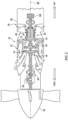
- FIG. 2 illustrates a side, cutaway view of an exemplary configuration for one of the engines 22.
- the engine 22 of FIG. 2 is configured as a turboprop gas turbine engine.
- the present disclosure is also applicable to other configurations of engines such as, but not limited to, a rotary engine (e.g., a Wankel engine), a piston engine, or the like.
- gas turbine engines such as, but not limited to, turboshaft gas turbine engines, turbofan gas turbine engines, turbojet gas turbine engines, propfan gas turbine engines, open rotor gas turbine engines, or the like.
- the engine 22 of FIG. 2 includes an air inlet 28, a compressor 30, a combustor 32, a high-pressure turbine 34, a power turbine 36, and an engine static structure 38.
- the air inlet 28, the compressor 30, the combustor 32, the high-pressure turbine 34, and the power turbine 36 are arranged along an axial centerline 40 (e.g., a rotational axis) of the engine 22.
- the engine static structure 38 may include, for example, one or more engine cases for the engine 22.
- the engine static structure 38 may additionally include cowlings, bearing assemblies, and/or other structural components of the engine 22.
- the one or more engine cases form, house, and/or structurally support one or more of the air inlet 28, the compressor 30, the combustor 32, the high-pressure turbine 34, and the power turbine 36.
- Components of the engine 22 of FIG. 2 such as components of the compressor 30, the high-pressure turbine 34, and the power turbine 36, are arranged as a first rotational assembly 42 (e.g., a high-pressure spool) and a second rotational assembly 44 (e.g., a power spool).
- the first rotational assembly 42 and the second rotational assembly 44 are mounted for rotation about the axial centerline 40 relative to the engine static structure 38.
- the first rotational assembly 42 includes a first shaft 46, a bladed compressor rotor 48 for the compressor 30, and a bladed first turbine rotor 50 for the high-pressure turbine 34.
- the first shaft 46 interconnects the bladed compressor rotor 48 and the bladed first turbine rotor 50.
- the second rotational assembly 44 includes a second shaft 52, a bladed second turbine rotor 54 for the power turbine 36, and a propulsor 56.
- the second shaft 52 is connected to the bladed second turbine rotor 54.
- the second shaft 52 may be directly or indirectly connected to the propulsor 56 (e.g., an input shaft of the propulsor 56).
- the second shaft 52 may be configured to rotatably drive the propulsor 56 via a gearbox assembly 58.
- the second rotation assembly 44 may include additional components (e.g., a main rotor input shaft) for interconnecting the second shaft 52 with the bladed second turbine rotor 54 and the propulsor 56.
- the gearbox assembly 58 may be configured to drive the propulsor 56 at a different (e.g., a reduced) rotational speed relative to the second shaft 52.
- the second shaft 52 may directly interconnect the bladed second turbine rotor 54 and the propulsor 56.
- the propulsor 56 of FIG. 2 is a propeller configured for providing propulsion (e.g., thrust) for the aircraft 1000, however, the propulsor 56 of the present disclosure is not limited to propeller configurations and may alternatively be configured as other rotational loads for effecting aircraft propulsion (e.g., a helicopter rotor, an open rotor, a bladed fan, etc.).
- ambient air enters the engine 22 through the air inlet 28 and is directed into the compressor 30.
- the ambient air is compressed by the bladed compressor rotor 48 and directed into a combustion chamber of the combustor 32.
- Fuel is injected into the combustion chamber and mixed with the compressed air to provide a fuel-air mixture.
- This fuel-air mixture is ignited, and combustion products thereof flow through and sequentially cause the bladed first turbine rotor 50 and the bladed second turbine rotor 54 to rotate.
- the rotation of the bladed first turbine rotor 50 and the bladed second turbine rotor 54 respectively drive rotation of the first rotational assembly 42 and the second rotational assembly 44.
- Rotation of the second rotational assembly 44 further drives rotation of the propulsor 56 to provide propulsion (e.g., thrust) for the aircraft 1000.
- propulsion e.g., thrust
- Combustion exhaust gas flowing past the bladed second turbine rotor 54 along is directed out of the engine 22 (e.g., through an exhaust).
- the controller 24 includes a processor 60 connected in signal communication with memory 62.
- the processor 60 may include any type of computing device, computational circuit, processor(s), CPU, computer, or the like capable of executing a series of instructions that are stored in the memory 62. Instructions can be directly executable or can be used to develop executable instructions. For example, instructions can be realized as executable or non-executable machine code or as instructions in a high-level language that can be compiled to produce executable or non-executable machine code. Further, instructions also can be realized as or can include data. Computer-executable instructions also can be organized in any format, including routines, subroutines, programs, data structures, objects, modules, applications, applets, functions, etc.
- the instructions may include an operating system, and/or executable software modules such as program files, system data, buffers, drivers, utilities, and the like.
- the executable instructions may apply to any functionality described herein to enable the engine assembly 22 to accomplish the same algorithmically and/or by coordination of components of the engine assembly 22.
- the memory 62 may include a single memory device or a plurality of memory devices; e.g., a computer-readable storage device that can be read, written, or otherwise accessed by a general purpose or special purpose computing device, including any processing electronics and/or processing circuitry capable of executing instructions.
- the present disclosure is not limited to any particular type of memory device, which may be non-transitory, and may include read-only memory, random access memory, volatile memory, non-volatile memory, static memory, dynamic memory, flash memory, cache memory, volatile or non-volatile semiconductor memory, optical disk storage, magnetic disk storage, magnetic tape, other magnetic storage devices, or any other medium capable of storing one or more instructions, and/or any device that stores digital information.
- the memory device(s) may be directly or indirectly coupled to the controller 24.
- the controller 24 may include, or may be in communication with, an input device that enables a user to enter data and/or instructions, and may include, or be in communication with, an output device configured, for example to display information (e.g., a visual display or a printer), or to transfer data, etc. Communications between the controller 24 and other electrical and/or electronic components (e.g., controllers, sensors, etc.) may be via a hardwire connection or via a wireless connection. A person of skill in the art will recognize that portions of the controller 24 may assume various forms (e.g., digital signal processor, analog device, etc.) capable of performing the functions described herein.
- the controller 24 may be a single electronic control unit or, alternatively, may be formed by a plurality of discrete electronic control units (e.g., one for each engine 22), which discrete electronic control units may be connected in signal communication with one another.
- the controller 24 may form or otherwise be part of an electronic engine controller (EEC) for one or more of the engines 22.
- the EEC may control operating parameters of one or more of the engines 22 including, but not limited to, fuel flow, stator vane position (e.g., variable compressor inlet guide vane (IGV) position), compressor air bleed valve position, shaft (e.g., first shaft 46 and/or second shaft 52) torque and/or rotation speed, etc. so as to control an engine power or performance of the one or more of the engines 22.
- the EEC may modulate fuel flow to the combustor 32 to obtain a desired output power of the engine 22.
- the EEC may modulate the fuel flow using a closed-loop process in which an output power or other operating parameter of the one or more of the engines 22 is measured and fuel flow is increased or decreased as a function of the measured output power or operational parameter.
- the controller 24 may include or otherwise be connected in signal communication with one or more sensors to measure and/or determine the output power or operational parameters of one or more of the engines 22 such as, but not limited, shaft rotation speed sensors, shaft torque sensors, fuel flow rate sensors, pressure sensors, temperature sensors, and the like.
- the EEC may be part of a full authority digital engine control (FADEC) system.
- FADEC full authority digital engine control
- the electrical distribution system 26 of FIG. 2 is configured to supply electrical power for electrical loads of the engines 22 and/or the aircraft 1000 (see FIG. 1 ).
- Examples of electrical loads for the aircraft 1000 include, but are not limited to, electronic control systems, environmental control systems, electric motors, lighting systems, communication systems, and the like.
- the electrical distribution system 26 may include a generator 64 for generating and supplying electric power for the electrical distribution system 26.
- the electrical distribution system 26 of FIG. 2 includes the generator 64 coupled to the first shaft 46. Rotation of the first shaft 46 drives the generator 64 (e.g., drives rotation of a rotor of the generator) to generate electrical power. While the generator 64 of FIG. 2 is coupled to the first shaft 46, the generator 64 may alternatively be connected to the second shaft 52.
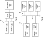
- FIG. 3 illustrates a block diagram of an exemplary configuration of the engine assembly 20.
- the engine assembly 20 of FIG. 3 includes a first engine 22A and a second engine 22B.
- the first engine 22A and the second engine 22B (e.g., respective output shafts of the first engine 22A and the second engine 22B) are coupled to a mechanical load 66.
- the first engine 22A and the second engine 22B are configured to power (e.g., drive, rotate, etc.) the mechanical load 66.
- Examples of the mechanical load 66 include a helicopter rotor, a propeller, an electrical generator rotor, or the like.
- the first engine 22A and the second engine 22B of FIG. 3 are coupled to the mechanical load 66 by a gear assembly 68.
- the gear assembly 68 transmits the rotational output of the first engine 22A and the second engine 22B to the mechanical load 66 to effect rotation of the mechanical load 66.
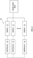
- FIG. 4 illustrates a block diagram of another exemplary configuration of the engine assembly 20.
- the engine assembly 20 of FIG. 4 includes a first engine 22C and a second engine 22D.
- the first engine 22C includes or is otherwise coupled (e.g., by an output shaft of the first engine 22C, a gear assembly, etc.) to a first generator 64C to drive the first generator 64C to generate electrical power.
- the second engine 22D includes or is otherwise coupled to (e.g., by an output shaft of the second engine 22D, a gear assembly, etc.) a second generator 64D to drive the second generator 64D to generate electrical power.
- the first generator 64C and the second generator 64D are electrically connected to an electrical distribution bus 70 of the electrical distribution system 26.
- One or more electrical loads 72 of the engines 22, 22C, 22D and/or the aircraft 1000 are electrically connected to the electrical distribution bus 70 to receive electrical power from the electrical distribution bus 70, such that the first engine 22C and the second engine 22D are configured to power (e.g., facilitate generation of electrical power for) the electrical loads 72.
- a plurality of engines may be used to power one or more fluctuating mechanical and/or electrical loads, as previously discussed.
- identical operational control rules e.g., implemented by an electronic control system
- fluctuating mechanical and/or electrical loads may contribute to high cyclic usage and wear of the engines due to frequent acceleration and deceleration cycles experienced by the engines when providing power for the fluctuating mechanical and/or electrical loads. This results in high engine operating costs as well as reduced reliability.
- the engines may all respond to fluctuating mechanical and/or electrical loads at a same rate, thereby facilitating a slower response of engine power to mechanical and/or electrical load demand.
- Fluctuation mechanical and/or electrical loads may be exhibited, for example, by propulsion system acceleration and deceleration transients (e.g., an aircraft takeoff procedure), electric motor operation (e.g., an electric motor for a hybrid-electric propulsion system), or the like.
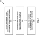
- FIG. 5 illustrates a flowchart for the Method 500.
- the Method 500 may be performed for the engine assembly 20, as described herein.
- the controller 24 may be used to execute or control one or more steps of the Method 500 for the engine assembly 20.
- the processor 60 may execute instructions stored in memory 62, thereby causing the controller 24 and/or its processor 60 to execute or otherwise control one or more steps of the Method 500.
- the Method 500 is not limited to use with the engine assembly 20, engines 22, and/or the controller 24. Unless otherwise noted herein, it should be understood that the steps of Method 500 are not required to be performed in the specific sequence in which they are discussed below and, in some embodiments, the steps of Method 500 may be performed separately or simultaneously.
- Step 502 includes identifying one or more engine characteristics for each of the engines 22.
- the controller 24 may identify the one or more engine characteristics for each of the engines 22, for example, continuously during operation of the engines 22.
- engine characteristics include, but are not limited to, accumulated engine loading cycles or other parameters indicative of engine operation and wear, engine efficiency, engine power output capacity, and engine responsiveness.
- the engine characteristics may be predetermined values (e.g., stored in memory 62) and/or dynamically determined values.
- One or more engine characteristics may be measured (e.g., using one or more sensors of the engines 22), calculated, synthesized, and/or modeled by the controller 24, or otherwise determined by the controller 24.
- the controller 24 may determine an engine efficiency of one or more of the engines 22 based on a comparison of combustor fuel flow to an engine output power or engine output torque of the respective engines 22. For further example, the controller 24 may determine an engine responsiveness of one or more of the engines 22 based on a comparison of a rate of change of engine output power and/or engine output torque to a change in target engine output power and/or target engine output torque.
- the engine characteristics for each of the engines 22 may be identified by a single controller 24 connected in signal communication with components (e.g., sensors) of each of the engines 22.
- each of the engines 22 may include or otherwise be controlled by a discrete controller 24 (e.g., a dedicated EEC or FADEC).
- Each of the controllers 24 may be connected in signal communication.
- Each of the controllers 24 may identify the engine characteristics for the respective one of the engines 22 and communicate the engine characteristics to the other controllers 24.
- Step 504 includes identifying an operating rule for each of the engines 22 using the engine characteristics identified for each of the engines 22.
- the operating rule for each of the engines 22 includes instructions (e.g., instructions stored in memory 62) which, when executed by the controller(s) 24 and/or its processor 60, cause the controller(s) 24 and/or its processor to control a responsiveness of each of the respective engines 22 to load demand (e.g., load fluctuation) from one or more loads (e.g., the mechanical loads 66 and/or the electrical loads 72; see FIGS. 3 and 4 ) which are shared by the engines 22.
- load demand e.g., load fluctuation
- the engine responsiveness controlled by the controller(s) 24 using the operating rule may be characterized, in general, by a target rate of change of engine power in response to changing load demand.
- the operating rule for each of the engines 22 may include other instructions which, when executed by the controller(s) 24 and/or its processor 60, cause the controller(s) 24 and/or its processor to control other operating parameters of each of the respective engines 22 such as, but not limited to, a torque, an engine power (e.g., a shaft horsepower (SHP)), and/or an engine power ratio (e.g., a ratio of power output of each engine 22 relative to a total power output of the engines 22 of the engine assembly 20).
- a torque e.g., a shaft horsepower (SHP)
- SHP shaft horsepower
- an engine power ratio e.g., a ratio of power output of each engine 22 relative to a total power output of the engines 22 of the engine assembly 20.
- the identified operating rule for each of the engines 22 may be different than the identified operating rule for one or more of the other engines 22. Accordingly, the operating rule for each of the engines 22 may be used to designate one or more of the engines 22 (e.g., engines 22 having a relatively higher responsiveness) for responding to fluctuating load demand while another one or more of the engines 22 (e.g., engines 22 having a relatively lower responsiveness) may be designated, for example, to maintain a relatively constant power output.
- an identified operating rule for a first of the engines 22 may include a first target rate of change of engine power and an identified operating rule for a second of the engines 22 may include a second target rate of change of engine power which is different than the first target rate of change of engine power.
- the second target rate of change of engine power may be less than that first target rate of change of engine power such that the second engine may be controlled to maintain a relatively constant power output while the first engine may be controlled to more rapidly change power in response to fluctuating loading demand.
- the identified operating rule for each of the first and the second of the engines 22 may additionally include a target engine power and/or a target engine power ratio.
- the identified operating rule for the first of the engines 22 may include a first target engine power ratio and the identified operating rule for the second of the engines 22 may include a second target engine power ratio which is greater than the first engine power ratio.
- the second of the engines 22 may, therefore, facilitate a high steady-state power output (e.g., base load power output) and greater efficiency relative to the first of the engines 22 which may facilitate a more rapid response to fluctuating load demand from loads of the aircraft 1000 and/or the engine assembly 20.
- the second of the engines 22 may experience fewer and/or less significant power output cycling and associated wear relative to the first of the engines 22.
- the identified operating rule for each of the engines 22 may include predetermined instructions assigned to each of the engines 22 and stored in memory 62.
- the identified operating rule for each of the engines 22 may be selected or otherwise determined by a pilot or other operator for the engine assembly 20 prior to operation of the engine assembly 20 (e.g., operation of the engine assembly 20 for a flight condition).
- the identified operating rule for each of the engines 22 may be dynamically determined (e.g., continuously measured or otherwise determined by the controller(s) 24), for example, based on the identified engine characteristics for each of the engines 22.
- a first of the engines 22 may have a first power output capacity and the second of the engines 22 may have a second power output capacity which is greater than the first power output capacity.
- the first of the engines 22 may have a first responsiveness which is greater than a second responsiveness of the second of the engines 22.
- the identified operating rule for the first of the engines 22 may include a first target engine power ratio and the identified operating rule for the second of the engines 22 may include a second target engine power ratio which is greater than the first engine power ratio, such that the second of the engines 22 (e.g., having a greater power output capacity) may facilitate a high steady-state power output and the first of the engines 22 (e.g., having a lower power output capacity and/or a greater responsiveness) may facilitate more rapid response to fluctuating load demand from loads of the aircraft 1000 and/or the engine assembly 20.
- a first of the engines 22 may have a high accumulation of engine loading cycles such that the first of the engines 22 may be at or close to an engine loading cycle threshold in which a maintenance action may be performed for the first of the engines 22.
- the operating rule for the first of the engines 22 may cause the first of the engines 22 to be operated at a steady-state power output while the second of the engines 22 may facilitate more rapid response to fluctuating load demand from loads of the aircraft 1000 and/or the engine assembly 20.
- the controller(s) 24 may identify operating rules for each of the engines 22 such that the engines 22, as a plurality, facilitate improved steady-state power output, efficiency, responsiveness, operational life, and/or maintenance cost in powering their shared electrical and/or mechanical loads.
- the controller(s) 24 may be configured to receive input from a pilot or other operator of the aircraft 1000 and/or its engines 22, which input may be used to further identify the operating rules for the engines 22. For example, the operator may select a relative weighting between steady-state performance, transient response performance (e.g., acceleration), and operating cost for the engines 22.
- the controller(s) 24 may identify the operating rules for the engines 22 using the identified engine characteristics for each of the engines 22 as well as the operator weighting input. For example, the operator may select transient response performance to be assigned the greatest weight by the controller(s) 24. As previously discussed, the controller(s) 24 may have determined an engine responsiveness and/or other performance characteristics of the engines 22 (see Step 502).
- the controller(s) 24 may then identify operating rules for the engines 22, which operating rules may cause the controller(s) 24 to operate each of the engines 22 at its maximum responsiveness (e.g., acceleration) capability to achieve the greatest responsiveness of the engines 22 to changes in total load demand (e.g., mechanical and electrical). Because performance of the engines 22 will vary over time and usage, the controller(s) 24 will monitor the one or more engine characteristics and modify (e.g., optimize) the operating rules as the one or more engine characteristics (e.g., responsiveness) change.
- maximum responsiveness e.g., acceleration
- total load demand e.g., mechanical and electrical
- Step 506 includes operating the engines 22 in accordance with the identified operating rule for each of the engines 22.
- the controller 24 may modulate fuel flow to a combustor (e.g., the combustor 32) or other combustion chamber of each of the engines 22 to obtain a desired engine power output of each of the engines 22.
- the controller 24 may modulate the fuel flow using a closed-loop process in which an engine power output or other operating parameter (e.g., torque, shaft horsepower (SHP), etc.) of the one or more of the engines 22 is measured and fuel flow is increased or decreased as a function of the measured engine power output or other operational parameter.
- the controller 24 may modulate the fuel flow in response to achieve the target rate of change of engine power, target engine power, target engine power ratio, and/or other instructions of the operating rule for each of the engines 22 (e.g., within a specified tolerance).
- any one of these structures may describe the operations as a sequential process, many of the operations can be performed in parallel or concurrently.
- the order of the operations may be rearranged.
- a process may correspond to a method, a function, a procedure, a subroutine, a subprogram, etc.
Landscapes
- Engineering & Computer Science (AREA)
- Chemical & Material Sciences (AREA)
- Combustion & Propulsion (AREA)
- Aviation & Aerospace Engineering (AREA)
- Mechanical Engineering (AREA)
- General Engineering & Computer Science (AREA)
- Supply And Distribution Of Alternating Current (AREA)
Applications Claiming Priority (1)
| Application Number | Priority Date | Filing Date | Title |
|---|---|---|---|
| US18/211,033 US20240417092A1 (en) | 2023-06-16 | 2023-06-16 | System and method for controlling engines of a multi-engine aircraft engine assembly |
Publications (2)
| Publication Number | Publication Date |
|---|---|
| EP4477866A2 true EP4477866A2 (de) | 2024-12-18 |
| EP4477866A3 EP4477866A3 (de) | 2025-03-12 |
Family
ID=91530203
Family Applications (1)
| Application Number | Title | Priority Date | Filing Date |
|---|---|---|---|
| EP24181768.3A Pending EP4477866A3 (de) | 2023-06-16 | 2024-06-12 | System und verfahren zur steuerung von motoren einer mehrmotorigen flugzeugmotoranordnung |
Country Status (3)
| Country | Link |
|---|---|
| US (1) | US20240417092A1 (de) |
| EP (1) | EP4477866A3 (de) |
| CA (1) | CA3241517A1 (de) |
Family Cites Families (29)
| Publication number | Priority date | Publication date | Assignee | Title |
|---|---|---|---|---|
| US6611748B2 (en) * | 2001-01-08 | 2003-08-26 | Safe Flight Instrument Corporation | Engine synchronization system |
| US20030176954A1 (en) * | 2001-10-12 | 2003-09-18 | Jaw Link C. | Tracking and control of gas turbine engine component damage/life |
| US6823675B2 (en) * | 2002-11-13 | 2004-11-30 | General Electric Company | Adaptive model-based control systems and methods for controlling a gas turbine |
| US7769507B2 (en) * | 2004-08-26 | 2010-08-03 | United Technologies Corporation | System for gas turbine health monitoring data fusion |
| US7546742B2 (en) * | 2004-12-08 | 2009-06-16 | General Electric Company | Gas turbine engine assembly and method of assembling same |
| US7725293B2 (en) * | 2006-12-07 | 2010-05-25 | General Electric Company | System and method for equipment remaining life estimation |
| EP2519863A1 (de) * | 2009-12-31 | 2012-11-07 | ABB Research Ltd. | Verfahren und steuersystem zur koordination der last eines kraftwerkes |
| US9342060B2 (en) * | 2010-09-14 | 2016-05-17 | United Technologies Corporation | Adaptive control for a gas turbine engine |
| US9026279B2 (en) * | 2012-06-06 | 2015-05-05 | Harris Corporation | Wireless engine monitoring system and configurable wireless engine sensors |
| FR3015428B1 (fr) * | 2013-12-20 | 2017-04-28 | Eurocopter France | Installation motrice disposant d'un moteur secondaire compensant les pertes de puissance des moteurs principaux pour un aeronef a voilure tournante |
| US20150295581A1 (en) * | 2014-04-10 | 2015-10-15 | Nec Laboratories America, Inc. | Distributed Cooperative Control for Microgrid Resynchronization and Reconnection |
| FR3023989B1 (fr) * | 2014-07-17 | 2016-08-26 | Airbus Helicopters | Architecture electrique d'un aeronef, aeronef et procede mis en oeuvre |
| US9932850B2 (en) * | 2015-02-03 | 2018-04-03 | General Electric Company | Correction system and method for gas turbine proportional droop governor |
| FR3033316B1 (fr) * | 2015-03-04 | 2018-04-06 | Airbus Helicopters | Procede et dispositif de determination et d'optimisation de parametres caracteristiques du fonctionnement d'un aeronef a voilure tournante |
| US10443543B2 (en) * | 2016-11-04 | 2019-10-15 | United Technologies Corporation | High compressor build clearance reduction |
| FR3065443B1 (fr) * | 2017-04-19 | 2021-01-01 | Airbus Group Sas | Methode pour la gestion de la dissymetrie au sein d’un systeme de propulsion distribuee |
| US20200056497A1 (en) * | 2018-08-17 | 2020-02-20 | United Technologies Corporation | Hybrid gas turbofan powered sub-idle descent mode |
| US10793284B2 (en) * | 2019-02-05 | 2020-10-06 | Bell Textron Inc. | Multimode clutch assemblies for rotorcraft |
| US11174013B2 (en) * | 2019-02-05 | 2021-11-16 | Textron Innovations Inc. | Failsafe multimode clutch assemblies for rotorcraft |
| US10788088B2 (en) * | 2019-02-05 | 2020-09-29 | Bell Textron Inc. | Multimode powertrains for rotorcraft |
| US11174015B2 (en) * | 2019-02-05 | 2021-11-16 | Textron Innovations Inc. | Multimode clutch assemblies having engagement status sensors |
| US11667392B2 (en) * | 2019-06-20 | 2023-06-06 | Pratt & Whitney Canada Corp. | Method and system for operating a rotorcraft engine |
| US11525410B2 (en) * | 2019-10-10 | 2022-12-13 | Pratt & Whitney Canada Corp. | Systems and methods for purging a fuel manifold of a gas turbine engine |
| EP3951150B1 (de) * | 2020-08-04 | 2023-04-19 | LEONARDO S.p.A. | Verfahren zur steuerung eines schwebefähigen flugzeugs und entsprechendes flugzeug |
| US12031479B2 (en) * | 2020-08-31 | 2024-07-09 | General Electric Company | Hybrid electric propulsion system load share |
| US11746711B2 (en) * | 2021-08-12 | 2023-09-05 | Pratt & Whitney Canada Corp. | Pulse width modulation drive for staged fuel manifolds |
| US11975860B2 (en) * | 2022-01-06 | 2024-05-07 | Textron Innovations Inc. | Reduced-engine operation technique for rotorcraft |
| US11639690B1 (en) * | 2022-05-05 | 2023-05-02 | Raytheon Technologies Corporation | Boost spool flow control and generator load matching via load compressor |
| US12215636B2 (en) * | 2022-09-12 | 2025-02-04 | Textron Innovations Inc. | Pulse modulation technique for gas turbine engines |
-
2023
- 2023-06-16 US US18/211,033 patent/US20240417092A1/en active Pending
-
2024
- 2024-06-12 CA CA3241517A patent/CA3241517A1/en active Pending
- 2024-06-12 EP EP24181768.3A patent/EP4477866A3/de active Pending
Also Published As
| Publication number | Publication date |
|---|---|
| CA3241517A1 (en) | 2025-05-23 |
| EP4477866A3 (de) | 2025-03-12 |
| US20240417092A1 (en) | 2024-12-19 |
Similar Documents
| Publication | Publication Date | Title |
|---|---|---|
| CN111271178B (zh) | 具有协调的电力汲取的电力系统 | |
| CA2898985C (en) | Operation of aircraft engines during transient conditions | |
| US12296941B2 (en) | System and method for controlling a propulsor for a hybrid-electric aircraft propulsion system | |
| KR20130140023A (ko) | 항공기 가스 터빈으로 인가되는 전기의 발생을 제어하기 위한 방법 및 상기 방법을 구현하는 장치 | |
| US20250223048A1 (en) | Method and unit for controlling a motor assembly | |
| US20240425188A1 (en) | Testing secondary power system of aircraft powerplant | |
| CA3254257A1 (en) | ENGINE ASSEMBLY FOR AIRCRAFT PROPULSION SYSTEM | |
| EP4464873A1 (de) | Bremssteuerungsanordnung für ein flugzeuggasturbinentriebwerk und verfahren zur verwendung davon | |
| EP4477866A2 (de) | System und verfahren zur steuerung von motoren einer mehrmotorigen flugzeugmotoranordnung | |
| EP4530454A1 (de) | Steuersystem und -verfahren für ein hybridelektrisches flugzeugantriebssystem | |
| EP4474630A1 (de) | System und verfahren zur steuerung von motoren einer mehrmotorigen flugzeugmotoranordnung | |
| EP4372220A1 (de) | Motorleistungsextraktionssystem und verfahren zur verwendung davon | |
| Wortmann et al. | Comparative assessment of transient characteristics of conventional and hybrid gas turbine engine | |
| US12509236B1 (en) | Control assembly for aircraft propulsion systems | |
| US12545418B2 (en) | Control assembly for aircraft propulsion systems | |
| US20260001653A1 (en) | Systems and methods for controlling an electric motor of an aircraft propulsion system | |
| US12535016B2 (en) | Systems and methods for identifying insufficient starter acceleration for an aircraft engine | |
| EP4663547A1 (de) | Flugzeugtriebwerk und betriebsmethode | |
| US20250084796A1 (en) | Engine assembly for an aircraft propulsion system | |
| US20260011187A1 (en) | Model and method for modeling operation of an aircraft hybrid electric propulsion system | |
| EP4484727A1 (de) | Testen eines sekundärstromsystems eines flugzeugtriebwerks | |
| EP4512713A1 (de) | Verfahren und vorrichtung zur aktiven dämpfung von schwingungen in einem hybrid-elektrischen flugzeugantriebssystem | |
| EP4530438A1 (de) | System und verfahren zur identifizierung von reibzuständen für eine triebwerksrotorkonfiguration | |
| CA3276952A1 (en) | Aircraft propulsion system and method for operating same |
Legal Events
| Date | Code | Title | Description |
|---|---|---|---|
| PUAI | Public reference made under article 153(3) epc to a published international application that has entered the european phase |
Free format text: ORIGINAL CODE: 0009012 |
|
| STAA | Information on the status of an ep patent application or granted ep patent |
Free format text: STATUS: THE APPLICATION HAS BEEN PUBLISHED |
|
| AK | Designated contracting states |
Kind code of ref document: A2 Designated state(s): AL AT BE BG CH CY CZ DE DK EE ES FI FR GB GR HR HU IE IS IT LI LT LU LV MC ME MK MT NL NO PL PT RO RS SE SI SK SM TR |
|
| PUAL | Search report despatched |
Free format text: ORIGINAL CODE: 0009013 |
|
| AK | Designated contracting states |
Kind code of ref document: A3 Designated state(s): AL AT BE BG CH CY CZ DE DK EE ES FI FR GB GR HR HU IE IS IT LI LT LU LV MC ME MK MT NL NO PL PT RO RS SE SI SK SM TR |
|
| RIC1 | Information provided on ipc code assigned before grant |
Ipc: F02C 9/42 20060101AFI20250206BHEP |
|
| STAA | Information on the status of an ep patent application or granted ep patent |
Free format text: STATUS: REQUEST FOR EXAMINATION WAS MADE |
|
| 17P | Request for examination filed |
Effective date: 20250912 |